US4421123A - Multiple sample needle valve - Google Patents
Multiple sample needle valveDownload PDFInfo
- Publication number
- US4421123A US4421123AUS06/325,704US32570481AUS4421123AUS 4421123 AUS4421123 AUS 4421123AUS 32570481 AUS32570481 AUS 32570481AUS 4421123 AUS4421123 AUS 4421123A
- Authority
- US
- United States
- Prior art keywords
- valve
- skirt
- annular
- chamber
- spike
- Prior art date
- Legal status (The legal status is an assumption and is not a legal conclusion. Google has not performed a legal analysis and makes no representation as to the accuracy of the status listed.)
- Expired - Fee Related
Links
Images


Classifications
- A—HUMAN NECESSITIES
- A61—MEDICAL OR VETERINARY SCIENCE; HYGIENE
- A61B—DIAGNOSIS; SURGERY; IDENTIFICATION
- A61B5/00—Measuring for diagnostic purposes; Identification of persons
- A61B5/15—Devices for taking samples of blood
- A61B5/150007—Details
- A61B5/150015—Source of blood
- A61B5/15003—Source of blood for venous or arterial blood
- A—HUMAN NECESSITIES
- A61—MEDICAL OR VETERINARY SCIENCE; HYGIENE
- A61B—DIAGNOSIS; SURGERY; IDENTIFICATION
- A61B5/00—Measuring for diagnostic purposes; Identification of persons
- A61B5/15—Devices for taking samples of blood
- A61B5/150007—Details
- A61B5/150206—Construction or design features not otherwise provided for; manufacturing or production; packages; sterilisation of piercing element, piercing device or sampling device
- A61B5/150221—Valves
- A—HUMAN NECESSITIES
- A61—MEDICAL OR VETERINARY SCIENCE; HYGIENE
- A61B—DIAGNOSIS; SURGERY; IDENTIFICATION
- A61B5/00—Measuring for diagnostic purposes; Identification of persons
- A61B5/15—Devices for taking samples of blood
- A61B5/153—Devices specially adapted for taking samples of venous or arterial blood, e.g. with syringes
- A61B5/154—Devices using pre-evacuated means
- A—HUMAN NECESSITIES
- A61—MEDICAL OR VETERINARY SCIENCE; HYGIENE
- A61B—DIAGNOSIS; SURGERY; IDENTIFICATION
- A61B5/00—Measuring for diagnostic purposes; Identification of persons
- A61B5/15—Devices for taking samples of blood
- A61B5/155—Devices specially adapted for continuous or multiple sampling, e.g. at predetermined intervals
- F—MECHANICAL ENGINEERING; LIGHTING; HEATING; WEAPONS; BLASTING
- F16—ENGINEERING ELEMENTS AND UNITS; GENERAL MEASURES FOR PRODUCING AND MAINTAINING EFFECTIVE FUNCTIONING OF MACHINES OR INSTALLATIONS; THERMAL INSULATION IN GENERAL
- F16K—VALVES; TAPS; COCKS; ACTUATING-FLOATS; DEVICES FOR VENTING OR AERATING
- F16K15/00—Check valves
- F16K15/14—Check valves with flexible valve members
- F16K15/141—Check valves with flexible valve members the closure elements not being fixed to the valve body
- A—HUMAN NECESSITIES
- A61—MEDICAL OR VETERINARY SCIENCE; HYGIENE
- A61B—DIAGNOSIS; SURGERY; IDENTIFICATION
- A61B5/00—Measuring for diagnostic purposes; Identification of persons
- A61B5/15—Devices for taking samples of blood
- A61B5/150992—Blood sampling from a fluid line external to a patient, such as a catheter line, combined with an infusion line; Blood sampling from indwelling needle sets, e.g. sealable ports, luer couplings or valves
Definitions
- this inventionrelates to blood sampling devices. More particularly, this invention relates to such devices for taking multiple sample collections.
- Many different forms of valve assemblieshave been designed in the past for controlling the direction of flow of fluids. These include, for example, ball and seat valves, duck bill valves, and cup-shaped or conical valves. It is the latter form of valve to which this invention is directed and such valves operate by compressing or folding their elastomeric skirts under sufficient pressure for permitting fluids to pass by around the skirt. Flow of fluid in the opposite direction, toward the center of the skirt has the effect of expanding the flexible skirt portion into sealing contact with the adjacent cooperating walls in the chamber where the skirt valve is fixed.
- U.S. Pat. No. 2,913,000discloses a cup-shaped flow control valve which operates in this manner.
- cup valveshave proved useful in multiple blood sampling assemblies, enabling the user to exchange evacuated blood collection tubes without undo leakage due to venous or tourniquet pressure, and while such assemblies have provided simple, inexpensive arrangements, they have not been entirely satisfactory in that the degree of leakage has been somewhat too high in some applications, and the support arrangement for the cup valve has not been substantial enough and configured in a manner whereby prevention of cocking of the valve is completely achieved.
- a cup valve arrangementwhich has the effect of reducing substantially to zero any leakage around the circumferential bottom edge of the skirt of the cup valve and, simultaneously, reducing the cocking of the valve from its normal position to acceptable limits.
- Thisis achieved by incorporating an annular spike or sealing ring adjacent the bottom edge of the skirt of the valve for enhancing the sealing effect between the valve skirt and the adjacent cooperating valve chamber walls.
- the internal pedestal support for the valvehas been enlarged and reconfigured to provide a more substantial support for the cup valve, for reducing any cocking thereof.
- a blood sampling assemblywith a valve member having a resilient skirt which has both a multiple sampling feature and the capability of acting as a check valve.
- a still further object of the inventionis to provide a cup-shaped check valve which operates to reduce substantially to zero any leakage around the valve in its closed position.
- a further object of the inventionis to provide a cup-shaped check valve and a blood sampling assembly therefore which may be mass produced in economical fashion.
- the valve assemblyin accordance herewith, has a resilient skirt which will collapse under sufficient pressure in one direction of flow, and which will expand against the walls of a fluid conduit or chamber in which it is positioned to prevent flow in the opposite direction.
- a protrusionPositioned centrally of the cup valve along the axis thereof is a protrusion which serves to cooperate with the pedestal support therefore to provide the support for the cup valve, in accordance herewith, in its various positions of operation.
- cup valve of the inventionmay be comprised of any conventional elastomer, such as natural or synthetic rubber. Satisfactory results have been achieved, in accordance herewith, with a natural rubber formulation number VL601M105 manufactured by Vernay Laboratories, Inc., Yellow Springs, Ohio.
- An advantage of the invention herein, as applied to multiple sampling needles,is that the one-way cup-valve prevents chemical additives within an evacuated container attached to the assembly, in accordance herewith, from entering the bloodstream. If a tourniquet is removed or loosened before the intravenous needle is withdrawn from the vein, a reverse pressure could cause backflow. With the improved structure, in accordance herewith, such a risk is eliminated. That is, the circumferential spike together with the bottom of the skirt of the cup valve in accordance herewith, when viewed in section, is in the form of a ring under compression. Any deflection thereof inwardly, causes convolution of that ring.
- the invention hereinincludes a substantially larger and differently configured pedestal centrally of the cup valve which serves as the support for the cup valve.
- This larger negative pressure hub pedestalhas the effect of maintaining the valve "squared". That is, the axis of the cup-shaped valve is maintained adjacent the axis of the pedestal support which supports it.
- FIG. 1is a cross-sectional view of a cup-shaped valve illustrating the invention
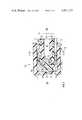
- FIG. 2is a partial longitudinal sectional view of a multiple sample blood collection assembly illustrating the invention, and incorporating the cup-shaped valve of FIG. 1;
- FIG. 3is a sectional view taken along lines III--III of FIG. 2.
- FIG. 1illustrates the cup-shaped valve 10 of the invention in section having a body portion 12 with an integral annular skirt 14.
- the skirt 14flares outwardly from the body portion 12 at about 7° from the longitudinal axis 13 of the valve.
- the annular skirt 14,defines the cup-shaped valve portion of the valve, in accordance herewith.
- An integral protrusion 18extends from body portion 12 along axis 13 of the valve.
- the protrusion 18serves to support the valve when mounted in the assembly, as discussed below.
- Surrounding the protrusion 18is an annular flat surface 32 which also serves to cooperate with the pedestal support for the valve in its assembled position, as discussed below.
- the protrusion 18is relatively thick at its point of attachment to the body portion 12 and tapers to a rounded end. Adjacent the lower end 35 of skirt 14, and spaced therefrom is an annular spike 20 extending outwardly from the skirt 14. This spike, in the assembled position of the valve, has the effect of enhancing the sealing engagement of the valve with the adjacent cooperating walls of the assembly, in accordance herewith.
- valve memberOn the side of valve body 12 opposite the skirt, the valve member includes a flattened annular projection 16 which is positioned equi-laterally of the axis 13 of the valve of the invention, and includes a flat surface 22 which is connected to body portion 12 by a tapered wall 24.
- the tapermay be, for example, about 20° relative to axis 13.
- the dimensions of the valve, in accordance herewith, as shown in FIG. 1may vary, according to the size of the assembly prepared for use.
- the diameter 36 of the valve, as illustrated in FIG. 1may be, for example, 0.194 inches plus or minus 0.003 inches.
- dimension 38 of the annular spike 20 extending from the outer wall of skirt 14is 0.005 inches. It should be understood, further that in molding the valve 10, the sealing surface of spike 20 must be continuous without any imperfection, in order to reduce to zero any leaks in the assembled position of the valve 10.
- the length 34 of pedestal 18is 0.06 inches, and the dimension 41 as shown in FIG. 1 is 0.11 inches.
- the width 42 of the bottom edge 35 of skirt 14is 0.008 inches.
- the dimension 30 adjacent the end of pedestal 18is 0.065 inches.
- the width 28 of flat surface 22 of the valve 10is 0.108 inches, while the width 26 of pedestal 18 where it joins body portion 12 is 0.04 inches. It is important in molding the valve, in accordance herewith, that no trim or flash is left to extend from the end surface 35 of skirt 14, because this has an effect on the sealing engagement properties of the valve, in its assembled position.
- FIG. 2a partial assembly of a multiple blood sampling arrangement, in accordance herewith, is shown with the assembly 50 having cooperating portions 52 from the I.V. end 56 of the assembly cooperating with the support pedestal 60, 62 of the negative pressure end 58 of the assembly.
- U.S. application Ser. No. 107,738, referred to abovefor details of the remaining portions of a blood sampling assembly, in accordance herewith, including the I.V. cannula mounting arrangement which is in flow communication with passage 54 for receiving and directing intravenous blood to chamber 72 in the direction of arrows 74.
- the supporting pedestal 60, 62in accordance herewith, extends from the negative pressure hub, as described in the co-pending application referred to above, and mounts a negative pressure cannula and a holder for receiving an evacuated tube, none of which parts are shown since they are conventional and are familiar to practitioners-in-the-art.
- the cup-shaped valve 10 of the inventionis mounted on a support pedestal-like assembly 60, 62 with the pedestal support, in the part shown in FIG. 2 being in the form of two halves, as illustrated in FIG. 3 with a central opening 37 for receiving the protrusion 18.
- the annular flat surface 32 of valve body 12cooperates with the annular flat surface 66 at the top of the pedestal support 60,62, as do the cooperating annular edges 39, 40.
- the pedestal support 60includes the additional annular dimension 62 which has a tapered upper surface 64 converging in the I.V. direction toward the longitudinal axis of the assembly.
- This additional supportin the configuration shown, serves to provide a more uniform support for the cup-shaped valve 10 in its mounted position.
- the cooperating flat surfaces together with the cooperating taper 64serve to limit the convolution of the lower edge 35 of the skirt portion 14 of the cup-shaped valve.
- the valve 10is not cocked out of alignment with the longitudinal axis of the assembly, shown in FIG. 2, more than 0.035 inches in the longitudinal direction of the assembly. That is, the lower annular end 35 of the cup-shaped valve assembly 10 does not move on either side of the longitudinal axis of the assembly shown in FIG. 2 longitudinally in either direction of the section line 76 more than 0.035 inches from the squared position as shown in FIG. 2.
- the dimension 68 of the prior art centrally arranged supportwas 0.10 inches
- the dimension 70which is the diameter of the support relative to the dimensions described previously for a representative cup valve 10, as discussed above, is 0.134 inches.
- the diameter of the support pedestalhas been increased substantially one-third and together with the taper 64 provides the "squared" support required for the valve assembly 10 to prevent the cocking thereof out of longitudinal alignment, as discussed above.
- the multiple blood sampling assemblyin accordance herewith operates in much the same manner as the assembly shown and described in U.S. patent application Ser. No. 107,738. That is, a holder is mounted on the negative pressure hub of the assembly. Thereafter, an intravenous cannula is made to penetrate a vein and blood flows through the cannula, then through passage 54 and into chamber 72. During this period of time, as will be appreciated, the cup-shaped valve 10, in accordance herewith, is in the position shown in FIG. 2 with the spike 20 in sealing engagement with the internal walls 78 of chamber 72.
- the valve member 20is constructed, as will be appreciated, so that blood does not pass therethrough under venous pressure, even if a tourniquet has been utilized.
- an evacuated tube having a resilient stoppermay be inserted at the negative pressure end of the assembly within the previously attached holder, in conventional manner.
- the evacuated tube stopperis pierced by the negative pressure cannula, under the large pressure differential the skirt 14 of valve 10 deflects inwardly adjacent the annular lower end 35 thereof to allow the flow of blood past annular spike 20 and into the evacuated tube.
- the tubeis removed from the holder at which time the skirt of the cup-shaped valve expands against the chamber walls 78 to prevent any reverse flow and contamination of a patient. It will be appreciated that, subsequently, a series of evacuated tubes may be connected to the assembly for a multiple sample taking of the blood.
- a one-way valveis provided in accordance herewith for a multiple blood sample needle assembly which valve operates to be self-sealing between the taking of each sample.
- a multiple blood sample assemblyis provided which includes an improved support pedestal for cooperation with the one-way valve, in accordance with this invention, to provide a much improved operating assembly for the taking of multiple blood samples.
- the arrangementis such that the possibility of the cup valve cocking out of alignment in a manner which would effectively negate the operating efficiency of the assembly, is eliminated, together with any leakage past the valve, in its closed position.
Landscapes
- Health & Medical Sciences (AREA)
- Life Sciences & Earth Sciences (AREA)
- Engineering & Computer Science (AREA)
- Molecular Biology (AREA)
- Animal Behavior & Ethology (AREA)
- Pathology (AREA)
- Physics & Mathematics (AREA)
- Biomedical Technology (AREA)
- Heart & Thoracic Surgery (AREA)
- Medical Informatics (AREA)
- Hematology (AREA)
- Surgery (AREA)
- Biophysics (AREA)
- General Health & Medical Sciences (AREA)
- Public Health (AREA)
- Veterinary Medicine (AREA)
- General Engineering & Computer Science (AREA)
- Manufacturing & Machinery (AREA)
- Mechanical Engineering (AREA)
- Measurement Of The Respiration, Hearing Ability, Form, And Blood Characteristics Of Living Organisms (AREA)
- Investigating Or Analysing Biological Materials (AREA)
- Infusion, Injection, And Reservoir Apparatuses (AREA)
Abstract
Description
Claims (11)
Priority Applications (6)
| Application Number | Priority Date | Filing Date | Title |
|---|---|---|---|
| US06/325,704US4421123A (en) | 1981-11-30 | 1981-11-30 | Multiple sample needle valve |
| AU89415/82AAU547620B2 (en) | 1981-11-30 | 1982-10-15 | Valve for multiple blood sample assembly |
| NZ202354ANZ202354A (en) | 1981-11-30 | 1982-11-01 | Cup valve for multiple blood sample assembly;annular spike on valve skirt prevents leakage |
| DE8282110450TDE3271202D1 (en) | 1981-11-30 | 1982-11-12 | Multiple sample needle valve |
| EP82110450AEP0080628B1 (en) | 1981-11-30 | 1982-11-12 | Multiple sample needle valve |
| JP57209221AJPS58103438A (en) | 1981-11-30 | 1982-11-29 | Multiple blood sampling apparatus and valve apparatus thereof |
Applications Claiming Priority (1)
| Application Number | Priority Date | Filing Date | Title |
|---|---|---|---|
| US06/325,704US4421123A (en) | 1981-11-30 | 1981-11-30 | Multiple sample needle valve |
Publications (1)
| Publication Number | Publication Date |
|---|---|
| US4421123Atrue US4421123A (en) | 1983-12-20 |
Family
ID=23269058
Family Applications (1)
| Application Number | Title | Priority Date | Filing Date |
|---|---|---|---|
| US06/325,704Expired - Fee RelatedUS4421123A (en) | 1981-11-30 | 1981-11-30 | Multiple sample needle valve |
Country Status (6)
| Country | Link |
|---|---|
| US (1) | US4421123A (en) |
| EP (1) | EP0080628B1 (en) |
| JP (1) | JPS58103438A (en) |
| AU (1) | AU547620B2 (en) |
| DE (1) | DE3271202D1 (en) |
| NZ (1) | NZ202354A (en) |
Cited By (16)
| Publication number | Priority date | Publication date | Assignee | Title |
|---|---|---|---|---|
| US4653513A (en)* | 1985-08-09 | 1987-03-31 | Dombrowski Mitchell P | Blood sampler |
| US4711250A (en)* | 1986-09-09 | 1987-12-08 | Gilbaugh Jr James H | Hand-held medical syringe actuator device |
| US5080654A (en)* | 1989-09-18 | 1992-01-14 | Applied Medical Technology, Inc. | Fluid injection device for intravenous delivery system |
| US5084034A (en)* | 1990-06-08 | 1992-01-28 | Tufts University | Method for sampling body fluids |
| US5088984A (en)* | 1990-10-03 | 1992-02-18 | Tri-State Hospital Supply Corporation | Medical connector |
| US5314416A (en)* | 1992-06-22 | 1994-05-24 | Sherwood Medical Company | Low friction syring assembly |
| US5549577A (en)* | 1993-12-29 | 1996-08-27 | Ivac Corporation | Needleless connector |
| US5579757A (en)* | 1994-02-02 | 1996-12-03 | Baxter International, Inc. | Anti-siphon flow restricter for a nebulizer |
| US5728078A (en)* | 1996-03-19 | 1998-03-17 | Powers Dental & Medical Technologies Inc. | Medical suctioning bacteria valve and related method |
| US5957898A (en)* | 1997-05-20 | 1999-09-28 | Baxter International Inc. | Needleless connector |
| US6261282B1 (en) | 1997-05-20 | 2001-07-17 | Baxter International Inc. | Needleless connector |
| US6579245B1 (en) | 1999-10-11 | 2003-06-17 | P. Z. “HTL”Spolka Akcyjna | Device for underpressuring collection and dosage liquid samples, in particular for analytic tests |
| US20080103517A1 (en)* | 2004-09-06 | 2008-05-01 | Termumo Kabushiki Kaisha | Lancet Instrument |
| US7635357B2 (en) | 1994-06-20 | 2009-12-22 | Mayer Bruno Franz P | Needleless injection site |
| US7713250B2 (en) | 2001-12-07 | 2010-05-11 | Becton, Dickinson And Company | Needleless luer access connector |
| US8864725B2 (en) | 2009-03-17 | 2014-10-21 | Baxter Corporation Englewood | Hazardous drug handling system, apparatus and method |
Families Citing this family (3)
| Publication number | Priority date | Publication date | Assignee | Title |
|---|---|---|---|---|
| DE3733810A1 (en)* | 1987-10-07 | 1989-04-20 | Becton Dickinson Gmbh | BLEEDING VALVE |
| EP0955491B1 (en)* | 1997-12-09 | 2000-09-27 | Sporting S.A. | Universal valve |
| JP4583872B2 (en)* | 2004-10-18 | 2010-11-17 | 積水化学工業株式会社 | Blood collection instrument |
Citations (18)
| Publication number | Priority date | Publication date | Assignee | Title |
|---|---|---|---|---|
| US274308A (en)* | 1883-03-20 | Pump-piston | ||
| US2128050A (en)* | 1937-05-29 | 1938-08-23 | Westinghouse Air Brake Co | Vent opening protector |
| DE826926C (en) | 1948-10-02 | 1952-01-07 | Paul Neunert | Self-opening and closing suction and pressure valves |
| US2663540A (en)* | 1949-08-24 | 1953-12-22 | Gen Motors Corp | Check valve for master cylinders |
| US2913000A (en)* | 1954-06-23 | 1959-11-17 | Baxter Don Inc | Flow control valve |
| US3022796A (en)* | 1958-03-25 | 1962-02-27 | Otis Eng Co | Check valves |
| US3122156A (en)* | 1959-10-21 | 1964-02-25 | Ronald C Kersh | Flexible check valve |
| US3331390A (en)* | 1964-07-06 | 1967-07-18 | Norgren Co C A | Check valve |
| GB1199498A (en) | 1967-03-29 | 1970-07-22 | Latex Products Proprietary Ltd | Non-Return Valve for Medical Uses. |
| US3817240A (en)* | 1972-06-28 | 1974-06-18 | Becton Dickinson Co | Multiple sample needle assembly with one-way valve and blood flow indicator |
| US3848579A (en)* | 1973-02-23 | 1974-11-19 | Real A Villa | Automatic elasto-valvular hypodermic sampling needle |
| US3905386A (en)* | 1974-04-22 | 1975-09-16 | Zurn Ind Inc | Valve |
| US3949780A (en)* | 1974-09-19 | 1976-04-13 | Buckman Thomas P | Two piece check valve |
| US4057050A (en)* | 1974-11-29 | 1977-11-08 | Sarstedt W | Devices for extracting blood |
| US4106497A (en)* | 1977-02-04 | 1978-08-15 | Becton, Dickinson And Company | Multiple sample needle assembly with indicator means |
| US4200097A (en)* | 1978-08-04 | 1980-04-29 | C. B. Fleet Company Incorporated | Disposable douche |
| US4207870A (en)* | 1978-06-15 | 1980-06-17 | Becton, Dickinson And Company | Blood sampling assembly having porous vent means vein entry indicator |
| US4307731A (en)* | 1978-06-15 | 1981-12-29 | Becton, Dickinson And Company | Multiple sampling needle having one-way valve |
Family Cites Families (1)
| Publication number | Priority date | Publication date | Assignee | Title |
|---|---|---|---|---|
| DE1892014U (en)* | 1964-02-29 | 1964-04-30 | Grohe Thermostat G M B H | NON-RETURN VALVE FOR LIQUIDS. |
- 1981
- 1981-11-30USUS06/325,704patent/US4421123A/ennot_activeExpired - Fee Related
- 1982
- 1982-10-15AUAU89415/82Apatent/AU547620B2/ennot_activeCeased
- 1982-11-01NZNZ202354Apatent/NZ202354A/enunknown
- 1982-11-12EPEP82110450Apatent/EP0080628B1/ennot_activeExpired
- 1982-11-12DEDE8282110450Tpatent/DE3271202D1/ennot_activeExpired
- 1982-11-29JPJP57209221Apatent/JPS58103438A/enactiveGranted
Patent Citations (19)
| Publication number | Priority date | Publication date | Assignee | Title |
|---|---|---|---|---|
| US274308A (en)* | 1883-03-20 | Pump-piston | ||
| US2128050A (en)* | 1937-05-29 | 1938-08-23 | Westinghouse Air Brake Co | Vent opening protector |
| DE826926C (en) | 1948-10-02 | 1952-01-07 | Paul Neunert | Self-opening and closing suction and pressure valves |
| US2663540A (en)* | 1949-08-24 | 1953-12-22 | Gen Motors Corp | Check valve for master cylinders |
| US2913000A (en)* | 1954-06-23 | 1959-11-17 | Baxter Don Inc | Flow control valve |
| US3022796A (en)* | 1958-03-25 | 1962-02-27 | Otis Eng Co | Check valves |
| US3122156A (en)* | 1959-10-21 | 1964-02-25 | Ronald C Kersh | Flexible check valve |
| US3331390A (en)* | 1964-07-06 | 1967-07-18 | Norgren Co C A | Check valve |
| GB1199498A (en) | 1967-03-29 | 1970-07-22 | Latex Products Proprietary Ltd | Non-Return Valve for Medical Uses. |
| US3601151A (en)* | 1967-03-29 | 1971-08-24 | Latex Products Proprietary Ltd | Nonreturn valves for medical uses |
| US3817240A (en)* | 1972-06-28 | 1974-06-18 | Becton Dickinson Co | Multiple sample needle assembly with one-way valve and blood flow indicator |
| US3848579A (en)* | 1973-02-23 | 1974-11-19 | Real A Villa | Automatic elasto-valvular hypodermic sampling needle |
| US3905386A (en)* | 1974-04-22 | 1975-09-16 | Zurn Ind Inc | Valve |
| US3949780A (en)* | 1974-09-19 | 1976-04-13 | Buckman Thomas P | Two piece check valve |
| US4057050A (en)* | 1974-11-29 | 1977-11-08 | Sarstedt W | Devices for extracting blood |
| US4106497A (en)* | 1977-02-04 | 1978-08-15 | Becton, Dickinson And Company | Multiple sample needle assembly with indicator means |
| US4207870A (en)* | 1978-06-15 | 1980-06-17 | Becton, Dickinson And Company | Blood sampling assembly having porous vent means vein entry indicator |
| US4307731A (en)* | 1978-06-15 | 1981-12-29 | Becton, Dickinson And Company | Multiple sampling needle having one-way valve |
| US4200097A (en)* | 1978-08-04 | 1980-04-29 | C. B. Fleet Company Incorporated | Disposable douche |
Cited By (24)
| Publication number | Priority date | Publication date | Assignee | Title |
|---|---|---|---|---|
| US4653513A (en)* | 1985-08-09 | 1987-03-31 | Dombrowski Mitchell P | Blood sampler |
| US4711250A (en)* | 1986-09-09 | 1987-12-08 | Gilbaugh Jr James H | Hand-held medical syringe actuator device |
| WO1988001882A1 (en)* | 1986-09-09 | 1988-03-24 | Gilbaugh James H | Hand-held medical syringe actuator device |
| US5080654A (en)* | 1989-09-18 | 1992-01-14 | Applied Medical Technology, Inc. | Fluid injection device for intravenous delivery system |
| US5084034A (en)* | 1990-06-08 | 1992-01-28 | Tufts University | Method for sampling body fluids |
| US5088984A (en)* | 1990-10-03 | 1992-02-18 | Tri-State Hospital Supply Corporation | Medical connector |
| US5314416A (en)* | 1992-06-22 | 1994-05-24 | Sherwood Medical Company | Low friction syring assembly |
| US5549577A (en)* | 1993-12-29 | 1996-08-27 | Ivac Corporation | Needleless connector |
| US5579757A (en)* | 1994-02-02 | 1996-12-03 | Baxter International, Inc. | Anti-siphon flow restricter for a nebulizer |
| US7635357B2 (en) | 1994-06-20 | 2009-12-22 | Mayer Bruno Franz P | Needleless injection site |
| US5728078A (en)* | 1996-03-19 | 1998-03-17 | Powers Dental & Medical Technologies Inc. | Medical suctioning bacteria valve and related method |
| US5868701A (en)* | 1996-03-19 | 1999-02-09 | Powers, Jr.; Carleton A. | Medical suctioning bacteria valve and related method |
| US6261282B1 (en) | 1997-05-20 | 2001-07-17 | Baxter International Inc. | Needleless connector |
| US6344033B1 (en) | 1997-05-20 | 2002-02-05 | Baxter International, Inc. | Needleless connector |
| US6669681B2 (en) | 1997-05-20 | 2003-12-30 | Baxter International Inc. | Needleless connector |
| US5957898A (en)* | 1997-05-20 | 1999-09-28 | Baxter International Inc. | Needleless connector |
| USRE43142E1 (en) | 1997-05-20 | 2012-01-24 | Baxter International, Inc. | Needleless connector |
| US6579245B1 (en) | 1999-10-11 | 2003-06-17 | P. Z. “HTL”Spolka Akcyjna | Device for underpressuring collection and dosage liquid samples, in particular for analytic tests |
| US7713250B2 (en) | 2001-12-07 | 2010-05-11 | Becton, Dickinson And Company | Needleless luer access connector |
| US20100179489A1 (en)* | 2001-12-07 | 2010-07-15 | Becton, Dickinson And Company | Needleless luer access connector |
| US7947032B2 (en) | 2001-12-07 | 2011-05-24 | Becton, Dickinson And Company | Needleless luer access connector |
| US20080103517A1 (en)* | 2004-09-06 | 2008-05-01 | Termumo Kabushiki Kaisha | Lancet Instrument |
| US8038694B2 (en)* | 2004-09-06 | 2011-10-18 | Terumo Kabushiki Kaisha | Lancet instrument |
| US8864725B2 (en) | 2009-03-17 | 2014-10-21 | Baxter Corporation Englewood | Hazardous drug handling system, apparatus and method |
Also Published As
| Publication number | Publication date |
|---|---|
| JPS58103438A (en) | 1983-06-20 |
| NZ202354A (en) | 1984-10-19 |
| DE3271202D1 (en) | 1986-06-19 |
| EP0080628A1 (en) | 1983-06-08 |
| JPH0113372B2 (en) | 1989-03-06 |
| AU547620B2 (en) | 1985-10-24 |
| AU8941582A (en) | 1983-06-09 |
| EP0080628B1 (en) | 1986-05-14 |
Similar Documents
| Publication | Publication Date | Title |
|---|---|---|
| US4421123A (en) | Multiple sample needle valve | |
| US4436519A (en) | Removable hemostasis valve | |
| US5817069A (en) | Valve assembly | |
| US4307731A (en) | Multiple sampling needle having one-way valve | |
| US3502097A (en) | Catheter-infuser connector | |
| US6273869B1 (en) | Valve connector | |
| US5843046A (en) | Catheter apparatus | |
| US5514116A (en) | Connector | |
| US5065783A (en) | Valve with self-sealing internal cannula | |
| US5509912A (en) | Connector | |
| EP0071329B1 (en) | Multiple sample needle assembly | |
| US8177760B2 (en) | Valved connector | |
| DE69523618T2 (en) | INTRAVENOUS CONNECTOR WITH VALVE FOR FLUID PIPE | |
| EP0042211B1 (en) | Multiple sample needle assembly | |
| US4909798A (en) | Universal hemostasis cannula | |
| US5092857A (en) | Hemostasis valve having support shoulders | |
| US5273533A (en) | Medical valve | |
| US4679571A (en) | Blood sample needle assembly with vein indicator | |
| US4317456A (en) | Multiple sample needle with anti-backflow valve | |
| US4456223A (en) | Flow control apparatus | |
| US5807347A (en) | Medical valve element | |
| IL139515A (en) | Medical valve with positive flow characteristics | |
| US4296759A (en) | Blood collection device and method with anti-backflow means | |
| US4540027A (en) | Check valve for infusion and transfusion apparatus | |
| WO1992004867A1 (en) | A blood sampling device |
Legal Events
| Date | Code | Title | Description |
|---|---|---|---|
| AS | Assignment | Owner name:BECTON, DICKINSON AND COMPANY, A CORP. OF NJ. Free format text:ASSIGNMENT OF ASSIGNORS INTEREST.;ASSIGNOR:PERCARPIO, EDWARD P.;REEL/FRAME:003957/0064 Effective date:19811120 Owner name:BECTON, DICKINSON AND COMPANY, NEW JERSEY Free format text:ASSIGNMENT OF ASSIGNORS INTEREST;ASSIGNOR:PERCARPIO, EDWARD P.;REEL/FRAME:003957/0064 Effective date:19811120 | |
| MAFP | Maintenance fee payment | Free format text:PAYMENT OF MAINTENANCE FEE, 4TH YEAR, PL 96-517 (ORIGINAL EVENT CODE: M170); ENTITY STATUS OF PATENT OWNER: LARGE ENTITY Year of fee payment:4 | |
| FEPP | Fee payment procedure | Free format text:SURCHARGE FOR LATE PAYMENT, PL 96-517 (ORIGINAL EVENT CODE: M176); ENTITY STATUS OF PATENT OWNER: LARGE ENTITY | |
| MAFP | Maintenance fee payment | Free format text:PAYMENT OF MAINTENANCE FEE, 8TH YEAR, PL 96-517 (ORIGINAL EVENT CODE: M171); ENTITY STATUS OF PATENT OWNER: LARGE ENTITY Year of fee payment:8 | |
| FEPP | Fee payment procedure | Free format text:PAYOR NUMBER ASSIGNED (ORIGINAL EVENT CODE: ASPN); ENTITY STATUS OF PATENT OWNER: LARGE ENTITY | |
| FEPP | Fee payment procedure | Free format text:MAINTENANCE FEE REMINDER MAILED (ORIGINAL EVENT CODE: REM.); ENTITY STATUS OF PATENT OWNER: LARGE ENTITY | |
| LAPS | Lapse for failure to pay maintenance fees | ||
| FP | Lapsed due to failure to pay maintenance fee | Effective date:19951220 | |
| STCH | Information on status: patent discontinuation | Free format text:PATENT EXPIRED DUE TO NONPAYMENT OF MAINTENANCE FEES UNDER 37 CFR 1.362 |