US4419693A - Error concealment in digital television signals - Google Patents
Error concealment in digital television signalsDownload PDFInfo
- Publication number
- US4419693A US4419693AUS06/248,861US24886181AUS4419693AUS 4419693 AUS4419693 AUS 4419693AUS 24886181 AUS24886181 AUS 24886181AUS 4419693 AUS4419693 AUS 4419693A
- Authority
- US
- United States
- Prior art keywords
- sample
- error
- sample signal
- signal
- algorithm
- Prior art date
- Legal status (The legal status is an assumption and is not a legal conclusion. Google has not performed a legal analysis and makes no representation as to the accuracy of the status listed.)
- Expired - Lifetime
Links
- 238000000034methodMethods0.000claimsabstractdescription24
- 238000012545processingMethods0.000claimsdescription2
- 239000011159matrix materialSubstances0.000description11
- 238000003860storageMethods0.000description10
- 238000012937correctionMethods0.000description7
- 238000013459approachMethods0.000description3
- 238000005070samplingMethods0.000description3
- 238000001228spectrumMethods0.000description2
- 238000012935AveragingMethods0.000description1
- 230000001419dependent effectEffects0.000description1
- 238000001514detection methodMethods0.000description1
- 238000009826distributionMethods0.000description1
- 230000000694effectsEffects0.000description1
- 238000001914filtrationMethods0.000description1
- 238000004519manufacturing processMethods0.000description1
- 238000012986modificationMethods0.000description1
- 230000004048modificationEffects0.000description1
- 238000011084recoveryMethods0.000description1
- 230000035945sensitivityEffects0.000description1
- 238000012360testing methodMethods0.000description1
Images


Classifications
- H—ELECTRICITY
- H04—ELECTRIC COMMUNICATION TECHNIQUE
- H04N—PICTORIAL COMMUNICATION, e.g. TELEVISION
- H04N5/00—Details of television systems
- H04N5/76—Television signal recording
- H04N5/91—Television signal processing therefor
- H04N5/93—Regeneration of the television signal or of selected parts thereof
- H—ELECTRICITY
- H04—ELECTRIC COMMUNICATION TECHNIQUE
- H04N—PICTORIAL COMMUNICATION, e.g. TELEVISION
- H04N9/00—Details of colour television systems
- H04N9/64—Circuits for processing colour signals
- H—ELECTRICITY
- H04—ELECTRIC COMMUNICATION TECHNIQUE
- H04N—PICTORIAL COMMUNICATION, e.g. TELEVISION
- H04N9/00—Details of colour television systems
- H04N9/79—Processing of colour television signals in connection with recording
- H04N9/87—Regeneration of colour television signals
- H04N9/88—Signal drop-out compensation
- H04N9/888—Signal drop-out compensation for signals recorded by pulse code modulation
Definitions
- This inventionrelates to error concealment in digital television signals.
- Such techniquesare, for example, used in some video tape recording arrangements where an incoming television signal to be recorded is sampled, the samples are coded into digital form, the digital data signals are recorded and subsequently reproduced by a video tape recorder (VTR), the reproduced digital data signals are decoded, and the decoded signals are used to form an analog signal corresponding to the original television signal.
- VTRvideo tape recorder
- the digital signalsare corrupted and then the reformed television signal does not correspond exactly to the original television signal, and a resulting television picture is degraded.
- correctionwhich involves the production and use of additional data signals purely for the purposes of error detection and correction, these additional data signals otherwise being redundant. While correction provides good results, it cannot generally be used as the sole means of dealing with errors, because a comprehensive correction capability would require an excessive amount of additional data which might overload the data handling paths or raise the data rate to an unacceptable level.
- concealmentThis comprises the replacement of corrupted data signals by data signals generated using available uncorrupted data signals. This method relies largely for accuracy on the strong correlation that exists in a television signal.
- a concealment technique using standard digital filtering in one dimensiongives the kind of response indicated in FIG. 1 of the accompanying drawings in which the concealment error is plotted as ordinates against the usable concealment frequencies as abscissae.
- the Nyquist fractionis the ratio of the frequency at which the concealment error exceeds a certain limit to the value of the Nyquist frequency. It will be seen from FIG. 1 that the Nyquist frequency represents the point on the graph at which concealment error rises rapidly to unacceptably poor levels.
- the current recommendation for the sampling frequency for digital television systemsis for a component system using 12 MHz for the luminance signal and 4 MHz for each of the color difference signals, the lower frequency being acceptable for the color difference signals because the eye is less sensitive to differences in color than to differences in luminance.
- the luminance Nyquist frequencyis therefore 6 MHz. If a Nyquist fraction of 0.85 is chosen, then the highest frequency which can satisfactory be concealed is 5.1 MHz.
- the concealmentwill only work correctly if all the samples which are to be used for concealment and which surround the sample in error are themselves error-free. Statistically, this situation is highly improbable. For example, if the off-tape error is one in 10 -5 and this error is taken as p, then two or more errors are likely to occur within a limit of ⁇ eight samples on either side of another error with a frequency which is approximately equal to 8.5 p 2 , which is 0.85 ⁇ 10 -9 . At present data rates this is approximately once every 6 seconds. However, two considerations are known to increase the error rate substantially.
- One object of the present inventionis to provide an improved method and apparatus for concealing errors in digital television signals.
- Another object of the present inventionis to provide a method and apparatus for concealing errors in digital television signals using selection of one correction algorithm from a plurality of correction algorithms.
- Another object of the present inventionis to provide a method and apparatus for concealing errors in digital television signals using sample values which are adjacent to an error sample value and which are located along a selected one of the horizontal, vertical, positive diagonal and negative diagonal directions of the television raster.
- a method of concealing errors in a digital television signalwhich television signal comprises a plurality of sample signals corresponding relatively to sample positions along a horizontal scan line of a television picture made up of a plurality of such lines, the method comprising, in respect of each said sample signal which is in error:
- Said methodmay comprise:
- said first and second algorithmsusing available sample signals located along respective different directions and/or in respective different dimensions of said television picture.
- apparatus for concealing errors in a digital television signalwhich television signal comprises a plurality of sample signals corresponding respective to sample positions along a horizontal scan line of a television picture made up of a plurality of such lines, the apparatus comprising:
- Said apparatusmay comprise:
- each said sample signalwhich is in error to use a first algorithm to calculate from available sample signals the expected value of a first sample signal corresponding to a first sample position adjacent to the same position of said error sample signal;
- said first and second algorithmsusing sample signals located along respective different directions and/or in respective different dimensions of said television picture.
- said different directions and/or different dimensions of said television picturecomprise four different directions, these directions being the horizontal, vertical, positive diagonal and negative diagonal directions of the television picture.
- the different dimensionsmay include not only the horizontal and vertical dimensions but also the time dimension, meaning preceding and succeeding frames or fields.
- the term "directions" as used in the description and in the claimsis intended to comprehend both the spacewise dimensions and the timewise dimension.
- FIG. 1is a graph illustrating the variation of concealment error with frequency
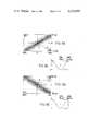
- FIG. 2shows a matrix of sample positions in a television picture
- FIG. 3Ashows the relationship between concealment and frequency in the horizontal direction
- FIG. 3Bshows the amplitude of concealment error in the horizontal direction as a section on the line X1-X2 of FIG. 3A;
- FIG. 4Ashows the relationship between concealment and frequency in the vertical direction
- FIG. 4Bshows the amplitude of concealment error in the vertical direction as a section on the line Y1-Y2 of FIG. 4A;
- FIG. 5Ashows the relationship between concealment and frequency in the positive diagonal direction
- FIG. 5Bshows the amplitude of concealment error in the positive diagonal direction as a section on the line Z1-Z2 of FIG. 5A;
- FIG. 6Ashows the relationship between concealment and frequency in the negative diagonal direction
- FIG. 6Bshows the amplitude of concealment error in the negative diagonal direction as a section on the line A1-A2 of FIG. 6A;
- FIGS. 7A, 7B and 7Cindicate the distribution of 1 dB, 3 dB, and 6 dB concealment error respectively;
- FIG. 8shows in simplified block form apparatus according to the invention for concealing errors in a digital television signal.
- thisshows part of a television raster, and in particular part of three consecutive horizontal scan lines labelled line n-1, line n and line n+1.
- the luminance sample positionsare disposed at regular intervals along each of the lines, the intervals corresponding to a luminance sampling frequency of 12 MHz, and the sample positions being aligned in the vertical direction. Reading from the left, consecutive sample positions in each line are labelled S-3, S-2, S-1, S0, S1, S2 and S3.
- any sample position in the matrixcan be designed by the line and the sample number, and for purposes of this discussion it is assumed that the sample position at which there is an error sample signal requiring concealment is in line n at position S0, this being designated n, S0.
- a corrected value for the sample position n, S0could be estimated in one of four different ways. Firstly, the average could be taken of the two samples in line n adjacent to and on each side of the sample position n, S0. Secondly, the average could be taken of the two sample values in line n-1 and line n+1 adjacent to and vertically above and below the sample position n, S0. Thirdly, the average could be taken of the two sample values in line n-1 and line n+1 and on either side of the sample position n, S0 along the positive diagonal direction. Fourthly, the average could be taken of the two sample values in line n-1 and line n+1 adjacent to and on either side of the sample position n, S0 and along the negative diagonal direction. These four directions are indicated by the arrows A, B, C and D respectively.
- each of these possibilitiesmay be thought of as an algorithm for calculating a corrected value, and it will be appreciated that it is likely that one of these algorithms will give a better result than any of the others.
- the preferred algorithm to be usedis therefore selected by testing each algorithm using known sample values to see which gives the best result.
- the first possibility mentioned abovecan be tested by using the sample values at the sample positions (n-1), S-1 and (n-1), S1 to calculate the value at the sample position (n-1), S0.
- the value at this latter positionis known, this provides a check on the accuracy of that algorithm when used for that particular television signal at that particular position.
- a similar checkcan be carried out using the same algorithm in respect of the line n+1.
- similar checkscan be carried out using the other three algorithms, and the algorithm giving the best result is selected.
- the results derived from the respective algorithmscan be weighted.
- a valuecan be placed on the likely accuracy of the results obtained. This is necessary because the distance between adjacent sample positions is less in the horizontal direction than in the vertical direction, the difference amounting to a factor of approximately 1.625. For this reason, the algorithm using the horizontal direction is in fact most likely to give the nearest result, with the algorithm for the vertical direction being next best, and the two algorithms for the diagonal directions being the next best thereafter.
- the decision of concealment directionis made by investigating the adjacent sample values and obtaining the concealment accuracy for each direction. If the concealment accuracy is H for the horizontal direction, V for the vertical direction, D + for the positive diagonal direction and D - for the negative diagonal direction, then these concealment accuracies can be defined as follows: ##EQU1## that is to say, the concealment accuracy H equals the average of the horizontal concealment accuracy from the horizontal line immediately above and the horizontal line immediately below the horizontal line containing the error sample.
- H, V, D + and D -represent the accuracy of concealment for the sample values most closely connected with the error sample.
- these valuesare each assigned a weighting coefficient to take account of the unequal spacings of the horizontal, vertical and diagonal samples. The smallest value is then used to select the direction of concealment.
- the methodcan be extended into the third dimension, that is to say the time dimension.
- the calculated valuesmay be determined making use of corresponding sample positions in one or more preceding and one or more succeeding fields or even frames of the television signal. This increases the number of algorithms available for use, but the actual algorithms selected for use and the number of algorithms (from two upwards) used will depend on the particular situation in which the invention is to be applied.
- the firstshows the relationship between concealment and frequency in the horizontal direction.
- the abbreviation cphmeans cycles per picture height.
- the secondshows the amplitude of the concealment error in the horizontal direction as a section on the line X1-X2 of FIG. 3A.
- FIGS. 4A and 4Bare similar except that they are for the vertical direction, and FIG. 4B is a section on the line Y1-Y2 of FIG. 4A.
- FIGS. 5A and 5Bare similar except that they are for the positive diagonal direction, and FIG. 5B is a section on the line Z1-Z2 of FIG. 5A.
- FIGS. 6A and 6Bare similar except that they are for the negative diagonal direction, and FIG. 6B is a section on the line A1-A2 of FIG. 6A.
- each of the responses shown in FIGS. 3 to 6shows zero error where the greatest density of sample frequencies exist, that is to say around zero frequency. Moreover, the responses cover most of the frequencies existing within the Nyquist limits in each direction.
- FIGS. 7A to 7Cshow the total potential coverage of the four concealment algorithms, the shaded area showing the frequencies not concealed to the required accuracy, the required accuracy being 1 dB in FIG. 7A, 3 dB in FIG. 7B and 6 dB in FIG. 7C.
- the scaling of the vertical and horizontal axestake account of the relative spatial positions of the adjacent sample positions in the vertical and horizontal directions, this ratio being approximately 1:1.625, as mentioned above.
- the methodhas been described as applied to the luminance channel, that is say concealment of errors occuring in luminance sample values. It is also necessary to consider the color difference channels, and here two possibilities arise.
- each color difference channelcan be provided with a separate concealment selection arrangement independent of the arrangement for the luminance channel.
- the first solution referred to aboveincreases the amount of hardware required by approximately three
- an alternative method which economizes on the amount of hardware requiredmakes use of the fact that the chrominance information is related to the luminance information. That is, where a chrominance edge exists, so usually does a luminance edge. Based on this assumption it is possible to select the direction of color difference concealment to be the same as that selected for luminance concealment.
- the chrominance samplesoccur at only one-third the frequency of the luminance samples along each horizontal line, a different set of weighting coefficients has to be used, these being optimized to the chrominance bandwidths.
- the apparatuscomprises a luminance sample storage means 1 to which luminance input samples are supplied by way of an input terminal 2.
- the luminance sample storage means 1supplies outputs to a luminance sample matrix storage means 3 which stores a moving matrix of sample values corresponding to the sample positions (n+1),S2; (n+1),S1; (n+1),S0; (n+1),S-1; (n+1),S-2; n,S1; n,S0; n,S-1; (n-1),S2; (n-1),S1; (n-1),S0; (n-1),S-1; and (n-1),S-2.
- Each of the concealment accuracy detectors 4 to 7is continuously supplied with the appropriate part of the sample matrix from the luminance sample matrix storage means 3.
- the horizontal concealment accuracy detector 4receives or selects the sample values necessary to calculate the concealment accuracy H using algorithm (1) above, and supplies a signal representing the concealment accuracy H by way of a weighting multiplier 8 to a luminance direction processor 12.
- the concealment accuracy detectors 5 to 7supply a respective signal representing the vertical concealment accuracy V, the positive diagonal concealment accuracy D + and the negative diagonal concealment accuracy D - by way of weighting multipliers 9, 10, and 11 respectively to the luminance direction processor 12.
- the weighting multipliers 8 to 11effect the weighting referred to above to compensate for the different distances between adjacent sample positions in the various directions.
- the weightingmay be done simply on the basis of distance between adjacent sample positions, in which case each weighting multiplier multiplies by the reciprocal of the distance between adjacent sample positions in the relevant direction. Other weightings can, however, be used.
- the luminance direction processor 12supplies an output signal representing the selected direction of concealment to a sample value calculator 13 which operates to select the appropriate samples from the luminance sample matrix storage means 3 and calculate therefrom the required concealment value to be used to conceal the error sample.
- the sample value calculator 13uses the sample values for the sample positions n,S-1 and n,S+1 to calculate the value to be used to conceal the error sample at the sample position n, S0.
- the concealment valueis supplied to a selector 14 to which a switching signal is supplied by way of a terminal 15.
- the selector 14is also supplied with the sample value from the sample position n,S0 by way of a terminal 16.
- the apparatus as so far describedoperates continuously, that is say concealment values are determined as described for every sample position and supplied to the selector 14. Only, however, when it has been determined that there is an error at a given sample position n,S0, is a signal supplied to the selector 14 by way of the terminal 15, whereupon the concealment value supplied from the calculator 13 is supplied to a luminance output terminal 17 in place of the sample value supplied by way of the terminal 16. At all other times, the sample value supplied by way of the terminal 16 is supplied to the luminance output terminal 17.
- the fact that there is an error at a given sample position n,Socan be determined in any suitable manner. For example, it may be determined that the data word representing the sample value is not valid. As a more specific example, suppose that each sample value is coded into a word in the sub-set of 10-bit words which consist of 5 "0" and 5 "1"; this being convenient for magnetic recording and reproduction because of the large number of transients and the ease of clock recovery. In this case any reproduced data word not having 5 "0” and 5 "1" is not a valid member of the sub-set and so is clearly an error. Thereupon a switching signal is supplied to the terminal 15.
- the apparatusmay also include arrangements for calculating concealment values for the color difference channels U and V. For simplicity, only that part of the apparatus necessary to calculate concealment values for the difference channel U is shown and will be described.
- the apparatuscomprises a chrominance sample storage means 21 to which chrominance input samples are supplied by way of an input terminal 22.
- the chrominance sample storage means 21supplies outputs to a chrominance signal matrix storage means 23 which stores a moving matrix of sample values corresponding to those listed above in connection with the luminance sample matrix storage means 3, but adjusted to take account of the different spacing between adjacent chrominance samples.
- the concealment accuracy detectors 4 to 7derive signals representing the horizontal, vertical, positive diagonal and negative diagonal concealment accuracies H, V, V + , and V - for the chrominance difference channel U and supply the signals by way of respective chrominance weighting multipliers 24, 25, 26, and 27 to a chrominance direction processor 28 which supplies an output signal representing the selected direction of concealment to a sample value calculator 29 which operates to select the appropriate samples from the chrominance sample matrix storage means 23 and calculate therefrom the required concealment value to be used to conceal the error sample.
- the concealment erroris supplied to a selector 30 to which a switching signal is supplied by way of a terminal 31.
- the selector 30is also supplied with the sample value from the sample position n,S0 by way of a terminal 32.
- the chrominance part of the apparatuspreferably operates continuously. Only, however, when it has been determined there is an error at a given sample position n,S0, is a signal supplied to the selector 30 by way of the terminal 31, whereupon the concealment value supplied from the calculator 29 is supplied to a chrominance output terminal 33 in place of the sample value supplied by way of the terminal 32.
- the chrominance part of the apparatusmay be duplicated for the color difference channel V or, alternatively, hardware can be saved by also using the algorithm selected for the color difference channel U for the color difference channel V.
- the inventionis not limited to any particular form of television system and it may, for example, equally well be applied to a television signal of the PAL system or the NTSC system. Moreover, the invention is not limited to concealment of errors which have arisen in the course of recording reproducing from a VTR, but may be used in any situation where errors have arisen in processing, transmitting or handling a digital television signal.
Landscapes
- Engineering & Computer Science (AREA)
- Multimedia (AREA)
- Signal Processing (AREA)
- Television Systems (AREA)
- Television Signal Processing For Recording (AREA)
- Processing Of Color Television Signals (AREA)
- Transmission Systems Not Characterized By The Medium Used For Transmission (AREA)
- Noise Elimination (AREA)
- Detection And Prevention Of Errors In Transmission (AREA)
- Color Television Systems (AREA)
- Two-Way Televisions, Distribution Of Moving Picture Or The Like (AREA)
Abstract
Description
Claims (14)
Applications Claiming Priority (2)
| Application Number | Priority Date | Filing Date | Title |
|---|---|---|---|
| GB8011090 | 1980-04-02 | ||
| GB8011090AGB2073534B (en) | 1980-04-02 | 1980-04-02 | Error concealment in digital television signals |
Publications (1)
| Publication Number | Publication Date |
|---|---|
| US4419693Atrue US4419693A (en) | 1983-12-06 |
Family
ID=10512566
Family Applications (1)
| Application Number | Title | Priority Date | Filing Date |
|---|---|---|---|
| US06/248,861Expired - LifetimeUS4419693A (en) | 1980-04-02 | 1981-03-30 | Error concealment in digital television signals |
Country Status (8)
| Country | Link |
|---|---|
| US (1) | US4419693A (en) |
| EP (1) | EP0037212B1 (en) |
| JP (1) | JPS56162582A (en) |
| AT (1) | ATE7640T1 (en) |
| AU (1) | AU540385B2 (en) |
| CA (1) | CA1181168A (en) |
| DE (1) | DE3163722D1 (en) |
| GB (1) | GB2073534B (en) |
Cited By (73)
| Publication number | Priority date | Publication date | Assignee | Title |
|---|---|---|---|---|
| US4484230A (en)* | 1981-02-04 | 1984-11-20 | Crosfield Electronics Limited | Image reproduction method and apparatus |
| US4586082A (en)* | 1982-05-26 | 1986-04-29 | Sony Corporation | Error concealment in digital television signals |
| US4605966A (en)* | 1982-05-14 | 1986-08-12 | Sony Corporation | Error concealment in digital television signals |
| US5360968A (en)* | 1992-01-17 | 1994-11-01 | Eastman Kodak Company | "Consensus sync" data-sampling systems and methods |
| US6151416A (en)* | 1999-02-12 | 2000-11-21 | Sony Corporation | Method and apparatus for adaptive class tap selection according to multiple classification |
| US6154761A (en)* | 1999-02-12 | 2000-11-28 | Sony Corporation | Classified adaptive multiple processing system |
| US6163868A (en)* | 1997-10-23 | 2000-12-19 | Sony Corporation | Apparatus and method for providing robust error recovery for errors that occur in a lossy transmission environment |
| US6170074B1 (en) | 1999-02-12 | 2001-01-02 | Sony Corporation | Source coding to provide for robust error recovery |
| US6178266B1 (en) | 1999-02-12 | 2001-01-23 | Sony Corporation | Method and apparatus for the recovery of compression constants in the encoded domain |
| US6192161B1 (en) | 1999-02-12 | 2001-02-20 | Sony Corporation | Method and apparatus for adaptive filter tap selection according to a class |
| US6282684B1 (en) | 1997-10-23 | 2001-08-28 | Sony Corporation | Apparatus and method for recovery of data in a lossy transmission environment |
| US6285396B1 (en) | 1997-08-11 | 2001-09-04 | Nds Limited | Glitch detector |
| US6295008B1 (en) | 1999-02-12 | 2001-09-25 | Sony Corporation | Method and apparatus for truncated decoding |
| US6307560B1 (en) | 1999-02-12 | 2001-10-23 | Sony Corporation | Classified adaptive spatio-temporal format conversion method and apparatus |
| US6307979B1 (en) | 1999-02-12 | 2001-10-23 | Sony Corporation | Classified adaptive error recovery method and apparatus |
| US6351494B1 (en) | 1999-09-24 | 2002-02-26 | Sony Corporation | Classified adaptive error recovery method and apparatus |
| US6363118B1 (en) | 1999-02-12 | 2002-03-26 | Sony Corporation | Apparatus and method for the recovery of compression constants in the encoded domain |
| US6389562B1 (en) | 1999-06-29 | 2002-05-14 | Sony Corporation | Source code shuffling to provide for robust error recovery |
| US6473876B1 (en) | 1999-06-29 | 2002-10-29 | Sony Corporation | Method and apparatus for encoding of bitstreams using rotation |
| US6493842B1 (en) | 1999-06-29 | 2002-12-10 | Sony Corporation | Time-varying randomization for data synchronization and implicit information transmission |
| US6519369B1 (en) | 1999-02-12 | 2003-02-11 | Sony Corporation | Method and apparatus for filter tap expansion |
| US6522785B1 (en) | 1999-09-24 | 2003-02-18 | Sony Corporation | Classified adaptive error recovery method and apparatus |
| US6529637B1 (en)* | 1989-05-22 | 2003-03-04 | Pixel Instruments Corporation | Spatial scan replication circuit |
| US6539517B1 (en) | 1999-11-09 | 2003-03-25 | Sony Corporation | Data transformation for explicit transmission of control information |
| US6549672B1 (en) | 1999-06-29 | 2003-04-15 | Sony Corporation | Method and apparatus for recovery of encoded data using central value |
| US6581170B1 (en) | 1997-10-23 | 2003-06-17 | Sony Corporation | Source coding to provide for robust error recovery during transmission losses |
| US6591398B1 (en) | 1999-02-12 | 2003-07-08 | Sony Corporation | Multiple processing system |
| US6621936B1 (en) | 1999-02-12 | 2003-09-16 | Sony Corporation | Method and apparatus for spatial class reduction |
| US6697489B1 (en) | 1999-03-30 | 2004-02-24 | Sony Corporation | Method and apparatus for securing control words |
| US6754371B1 (en) | 1999-12-07 | 2004-06-22 | Sony Corporation | Method and apparatus for past and future motion classification |
| US20040247165A1 (en)* | 2003-03-07 | 2004-12-09 | Kabushiki Kaisha Toshiba | Image processing apparatus and image processing method |
| US20050099538A1 (en)* | 2000-09-08 | 2005-05-12 | Wredenhagen G. F. | Method and apparatus for motion adaptive deinterlacing |
| US20050243205A1 (en)* | 2001-09-10 | 2005-11-03 | Jaldi Semiconductor Corp. | System and method for reducing noise in images |
| US7010737B2 (en) | 1999-02-12 | 2006-03-07 | Sony Corporation | Method and apparatus for error data recovery |
| US7039614B1 (en) | 1999-11-09 | 2006-05-02 | Sony Corporation | Method for simulcrypting scrambled data to a plurality of conditional access devices |
| US7039938B2 (en) | 2002-01-02 | 2006-05-02 | Sony Corporation | Selective encryption for video on demand |
| US7120250B2 (en) | 2002-09-09 | 2006-10-10 | Sony Corporation | Content distribution for multiple digital rights management |
| US7124303B2 (en) | 2001-06-06 | 2006-10-17 | Sony Corporation | Elementary stream partial encryption |
| US7155012B2 (en) | 2002-01-02 | 2006-12-26 | Sony Corporation | Slice mask and moat pattern partial encryption |
| US7215770B2 (en) | 2002-01-02 | 2007-05-08 | Sony Corporation | System and method for partially encrypted multimedia stream |
| US7218738B2 (en)* | 2002-01-02 | 2007-05-15 | Sony Corporation | Encryption and content control in a digital broadcast system |
| US7225164B1 (en) | 2000-02-15 | 2007-05-29 | Sony Corporation | Method and apparatus for implementing revocation in broadcast networks |
| US7233669B2 (en) | 2002-01-02 | 2007-06-19 | Sony Corporation | Selective encryption to enable multiple decryption keys |
| US7263187B2 (en) | 2003-10-31 | 2007-08-28 | Sony Corporation | Batch mode session-based encryption of video on demand content |
| US7286667B1 (en) | 2003-09-15 | 2007-10-23 | Sony Corporation | Decryption system |
| US7292692B2 (en) | 2003-03-25 | 2007-11-06 | Sony Corporation | Content scrambling with minimal impact on legacy devices |
| US7292691B2 (en) | 2002-01-02 | 2007-11-06 | Sony Corporation | Progressive video refresh slice detection |
| US7302059B2 (en) | 2002-01-02 | 2007-11-27 | Sony Corporation | Star pattern partial encryption |
| US7343013B2 (en) | 2003-12-16 | 2008-03-11 | Sony Corporation | Composite session-based encryption of video on demand content |
| US7346163B2 (en) | 2003-10-31 | 2008-03-18 | Sony Corporation | Dynamic composition of pre-encrypted video on demand content |
| US7350082B2 (en) | 2001-06-06 | 2008-03-25 | Sony Corporation | Upgrading of encryption |
| US7376233B2 (en) | 2002-01-02 | 2008-05-20 | Sony Corporation | Video slice and active region based multiple partial encryption |
| US7382929B2 (en) | 1989-05-22 | 2008-06-03 | Pixel Instruments Corporation | Spatial scan replication circuit |
| US7409702B2 (en) | 2003-03-20 | 2008-08-05 | Sony Corporation | Auxiliary program association table |
| US7508942B2 (en) | 2002-11-05 | 2009-03-24 | Sony Corporation | Multi-process descrambler |
| US7530084B2 (en) | 2002-05-28 | 2009-05-05 | Sony Corporation | Method and apparatus for synchronizing dynamic graphics |
| US7555464B2 (en) | 2006-03-01 | 2009-06-30 | Sony Corporation | Multiple DRM management |
| US7565546B2 (en) | 1999-03-30 | 2009-07-21 | Sony Corporation | System, method and apparatus for secure digital content transmission |
| US7620180B2 (en) | 2003-11-03 | 2009-11-17 | Sony Corporation | Preparation of content for multiple conditional access methods in video on demand |
| US7730300B2 (en) | 1999-03-30 | 2010-06-01 | Sony Corporation | Method and apparatus for protecting the transfer of data |
| US7747853B2 (en) | 2001-06-06 | 2010-06-29 | Sony Corporation | IP delivery of secure digital content |
| US7765567B2 (en) | 2002-01-02 | 2010-07-27 | Sony Corporation | Content replacement by PID mapping |
| US7823174B2 (en) | 2002-01-02 | 2010-10-26 | Sony Corporation | Macro-block based content replacement by PID mapping |
| US7853980B2 (en) | 2003-10-31 | 2010-12-14 | Sony Corporation | Bi-directional indices for trick mode video-on-demand |
| US7895617B2 (en) | 2004-12-15 | 2011-02-22 | Sony Corporation | Content substitution editor |
| US7895616B2 (en) | 2001-06-06 | 2011-02-22 | Sony Corporation | Reconstitution of program streams split across multiple packet identifiers |
| US8041190B2 (en) | 2004-12-15 | 2011-10-18 | Sony Corporation | System and method for the creation, synchronization and delivery of alternate content |
| US8072539B1 (en) | 1993-07-26 | 2011-12-06 | Cooper J Carl | Apparatus and method for digital processing of analog television signals |
| US8185921B2 (en) | 2006-02-28 | 2012-05-22 | Sony Corporation | Parental control of displayed content using closed captioning |
| US8572408B2 (en) | 2002-11-05 | 2013-10-29 | Sony Corporation | Digital rights management of a digital device |
| US8645988B2 (en) | 2002-12-13 | 2014-02-04 | Sony Corporation | Content personalization for digital content |
| US8667525B2 (en) | 2002-12-13 | 2014-03-04 | Sony Corporation | Targeted advertisement selection from a digital stream |
| US8818896B2 (en) | 2002-09-09 | 2014-08-26 | Sony Corporation | Selective encryption with coverage encryption |
Families Citing this family (12)
| Publication number | Priority date | Publication date | Assignee | Title |
|---|---|---|---|---|
| GB2084432A (en)* | 1980-09-18 | 1982-04-07 | Sony Corp | Error concealment in digital television signals |
| US4377820A (en)* | 1981-04-30 | 1983-03-22 | Rca Corporation | Adaptive error concealment |
| JPH0799804B2 (en)* | 1981-07-13 | 1995-10-25 | ソニー株式会社 | Filter device |
| JPS5898814A (en)* | 1981-12-08 | 1983-06-11 | Sony Corp | Error data interpolating device |
| US4470065A (en)* | 1982-03-25 | 1984-09-04 | Rca Corporation | Adaptive error concealment using horizontal information determination from adjacent lines |
| GB2140189B (en)* | 1983-05-19 | 1986-04-30 | Sony Corp | Digital video tape recorder apparatus |
| JPH0828064B2 (en)* | 1984-01-21 | 1996-03-21 | ソニー株式会社 | Signal interpolator |
| US4630307A (en)* | 1984-09-10 | 1986-12-16 | Eastman Kodak Company | Signal processing method and apparatus for sampled image signals |
| GB2164521B (en)* | 1984-09-18 | 1988-02-03 | Sony Corp | Error concealment in digital television signals |
| US4630102A (en)* | 1984-10-10 | 1986-12-16 | Rca Corporation | Digital chroma overload system |
| JPS62266987A (en)* | 1986-05-15 | 1987-11-19 | Sony Corp | Correction device for two dimensional digital signal |
| JP3018366B2 (en)* | 1989-02-08 | 2000-03-13 | ソニー株式会社 | Video signal processing circuit |
Citations (3)
| Publication number | Priority date | Publication date | Assignee | Title |
|---|---|---|---|---|
| US3946432A (en)* | 1974-10-10 | 1976-03-23 | Cbs Inc. | Apparatus for digitally encoding a television signal |
| US4275418A (en)* | 1978-09-14 | 1981-06-23 | Micro Consultants Limited | Video noise reduction systems |
| US4365273A (en)* | 1979-11-05 | 1982-12-21 | Dainippon Screen Seizo Kabushiki Kaisha | Picture data compressing method |
Family Cites Families (7)
| Publication number | Priority date | Publication date | Assignee | Title |
|---|---|---|---|---|
| US3697948A (en)* | 1970-12-18 | 1972-10-10 | Ibm | Apparatus for correcting two groups of multiple errors |
| GB1599156A (en)* | 1976-12-24 | 1981-09-30 | Indep Broadcasting Authority | Recording digital signals |
| JPS5380105A (en)* | 1976-12-24 | 1978-07-15 | Sony Corp | Digital signal transmission method |
| GB2008888B (en)* | 1977-10-27 | 1982-06-30 | Quantel Ltd | Drop-out compensation system |
| JPS54143017A (en)* | 1978-04-28 | 1979-11-07 | Sony Corp | Time base error correction unit |
| JPS5573909A (en)* | 1978-11-28 | 1980-06-04 | Matsushita Electric Ind Co Ltd | Signal processor |
| US4376955A (en)* | 1980-02-28 | 1983-03-15 | Rca Corporation | Two dimensional adaptive dropout compensator and chroma inverter |
- 1980
- 1980-04-02GBGB8011090Apatent/GB2073534B/ennot_activeExpired
- 1981
- 1981-03-18ATAT81301156Tpatent/ATE7640T1/ennot_activeIP Right Cessation
- 1981-03-18EPEP81301156Apatent/EP0037212B1/ennot_activeExpired
- 1981-03-18DEDE8181301156Tpatent/DE3163722D1/ennot_activeExpired
- 1981-03-26AUAU68782/81Apatent/AU540385B2/ennot_activeExpired
- 1981-03-27CACA000374014Apatent/CA1181168A/ennot_activeExpired
- 1981-03-30USUS06/248,861patent/US4419693A/ennot_activeExpired - Lifetime
- 1981-04-02JPJP4984781Apatent/JPS56162582A/enactiveGranted
Patent Citations (3)
| Publication number | Priority date | Publication date | Assignee | Title |
|---|---|---|---|---|
| US3946432A (en)* | 1974-10-10 | 1976-03-23 | Cbs Inc. | Apparatus for digitally encoding a television signal |
| US4275418A (en)* | 1978-09-14 | 1981-06-23 | Micro Consultants Limited | Video noise reduction systems |
| US4365273A (en)* | 1979-11-05 | 1982-12-21 | Dainippon Screen Seizo Kabushiki Kaisha | Picture data compressing method |
Non-Patent Citations (1)
| Title |
|---|
| SMPTE Journal, vol. 87, No. 3, pp. 129-133, Mar. 1978.* |
Cited By (105)
| Publication number | Priority date | Publication date | Assignee | Title |
|---|---|---|---|---|
| US4484230A (en)* | 1981-02-04 | 1984-11-20 | Crosfield Electronics Limited | Image reproduction method and apparatus |
| US4605966A (en)* | 1982-05-14 | 1986-08-12 | Sony Corporation | Error concealment in digital television signals |
| US4586082A (en)* | 1982-05-26 | 1986-04-29 | Sony Corporation | Error concealment in digital television signals |
| US7986851B2 (en) | 1989-05-22 | 2011-07-26 | Cooper J Carl | Spatial scan replication circuit |
| US7382929B2 (en) | 1989-05-22 | 2008-06-03 | Pixel Instruments Corporation | Spatial scan replication circuit |
| US6529637B1 (en)* | 1989-05-22 | 2003-03-04 | Pixel Instruments Corporation | Spatial scan replication circuit |
| US7822284B2 (en) | 1989-05-22 | 2010-10-26 | Carl Cooper | Spatial scan replication circuit |
| US5360968A (en)* | 1992-01-17 | 1994-11-01 | Eastman Kodak Company | "Consensus sync" data-sampling systems and methods |
| US8072539B1 (en) | 1993-07-26 | 2011-12-06 | Cooper J Carl | Apparatus and method for digital processing of analog television signals |
| US6285396B1 (en) | 1997-08-11 | 2001-09-04 | Nds Limited | Glitch detector |
| US6963999B2 (en) | 1997-10-23 | 2005-11-08 | Sony Corporation | Source coding to provide for robust error recovery during transmission losses |
| US6212663B1 (en) | 1997-10-23 | 2001-04-03 | Sony Corporation | Apparatus and method for recovery of quantization codes in a lossy transmission environment |
| US6263468B1 (en) | 1997-10-23 | 2001-07-17 | Sony Corporation | Apparatus and method for partial buffering transmitted data to provide robust error recovery in a lossy transmission environment |
| US6263108B1 (en) | 1997-10-23 | 2001-07-17 | Sony Corporation | Apparatus and method for recovery of lost/damaged data in a bitstream of data based on compatibility of adjacent blocks of data |
| US6282684B1 (en) | 1997-10-23 | 2001-08-28 | Sony Corporation | Apparatus and method for recovery of data in a lossy transmission environment |
| US6163868A (en)* | 1997-10-23 | 2000-12-19 | Sony Corporation | Apparatus and method for providing robust error recovery for errors that occur in a lossy transmission environment |
| US6298085B1 (en) | 1997-10-23 | 2001-10-02 | Sony Corporation | Source encoding using shuffling of data to provide robust error recovery in a burst error-environment |
| US20030196159A1 (en)* | 1997-10-23 | 2003-10-16 | Tetsujiro Kondo | Source coding to provide for robust error recovery during transmission losses |
| US6581170B1 (en) | 1997-10-23 | 2003-06-17 | Sony Corporation | Source coding to provide for robust error recovery during transmission losses |
| US6311297B1 (en) | 1997-10-23 | 2001-10-30 | Sony Corporation | Apparatus and method for mapping an image to blocks to provide for robust error recovery in a lossy transmission environment |
| US6332042B1 (en) | 1997-10-23 | 2001-12-18 | Sony Corporation | Apparatus and method for encoding and decoding data in a lossy transmission environment |
| US7010737B2 (en) | 1999-02-12 | 2006-03-07 | Sony Corporation | Method and apparatus for error data recovery |
| US6307560B1 (en) | 1999-02-12 | 2001-10-23 | Sony Corporation | Classified adaptive spatio-temporal format conversion method and apparatus |
| US6151416A (en)* | 1999-02-12 | 2000-11-21 | Sony Corporation | Method and apparatus for adaptive class tap selection according to multiple classification |
| US6154761A (en)* | 1999-02-12 | 2000-11-28 | Sony Corporation | Classified adaptive multiple processing system |
| US6170074B1 (en) | 1999-02-12 | 2001-01-02 | Sony Corporation | Source coding to provide for robust error recovery |
| US6519369B1 (en) | 1999-02-12 | 2003-02-11 | Sony Corporation | Method and apparatus for filter tap expansion |
| US6363118B1 (en) | 1999-02-12 | 2002-03-26 | Sony Corporation | Apparatus and method for the recovery of compression constants in the encoded domain |
| US6178266B1 (en) | 1999-02-12 | 2001-01-23 | Sony Corporation | Method and apparatus for the recovery of compression constants in the encoded domain |
| US6535148B1 (en) | 1999-02-12 | 2003-03-18 | Sony Corporation | Method and apparatus for truncated decoding |
| US6192161B1 (en) | 1999-02-12 | 2001-02-20 | Sony Corporation | Method and apparatus for adaptive filter tap selection according to a class |
| US6295008B1 (en) | 1999-02-12 | 2001-09-25 | Sony Corporation | Method and apparatus for truncated decoding |
| US6859493B2 (en) | 1999-02-12 | 2005-02-22 | Sony Corporation | Apparatus and method for the recovery of compression constants in the encoded domain |
| US6307979B1 (en) | 1999-02-12 | 2001-10-23 | Sony Corporation | Classified adaptive error recovery method and apparatus |
| US6591398B1 (en) | 1999-02-12 | 2003-07-08 | Sony Corporation | Multiple processing system |
| US6621936B1 (en) | 1999-02-12 | 2003-09-16 | Sony Corporation | Method and apparatus for spatial class reduction |
| US7925016B2 (en) | 1999-03-30 | 2011-04-12 | Sony Corporation | Method and apparatus for descrambling content |
| US7565546B2 (en) | 1999-03-30 | 2009-07-21 | Sony Corporation | System, method and apparatus for secure digital content transmission |
| US6697489B1 (en) | 1999-03-30 | 2004-02-24 | Sony Corporation | Method and apparatus for securing control words |
| US7302058B2 (en) | 1999-03-30 | 2007-11-27 | Sony Corporation | Method and apparatus for securing control words |
| US7730300B2 (en) | 1999-03-30 | 2010-06-01 | Sony Corporation | Method and apparatus for protecting the transfer of data |
| US6389562B1 (en) | 1999-06-29 | 2002-05-14 | Sony Corporation | Source code shuffling to provide for robust error recovery |
| US7224838B2 (en) | 1999-06-29 | 2007-05-29 | Tetsujiro Kondo | Method and apparatus for recovery of encoded data using central value |
| US6553381B2 (en) | 1999-06-29 | 2003-04-22 | Sony Corporation | Time-varying randomization for data synchronization and implicit information transmission |
| US6549672B1 (en) | 1999-06-29 | 2003-04-15 | Sony Corporation | Method and apparatus for recovery of encoded data using central value |
| US6473876B1 (en) | 1999-06-29 | 2002-10-29 | Sony Corporation | Method and apparatus for encoding of bitstreams using rotation |
| US6493842B1 (en) | 1999-06-29 | 2002-12-10 | Sony Corporation | Time-varying randomization for data synchronization and implicit information transmission |
| US6522785B1 (en) | 1999-09-24 | 2003-02-18 | Sony Corporation | Classified adaptive error recovery method and apparatus |
| US6351494B1 (en) | 1999-09-24 | 2002-02-26 | Sony Corporation | Classified adaptive error recovery method and apparatus |
| US6539517B1 (en) | 1999-11-09 | 2003-03-25 | Sony Corporation | Data transformation for explicit transmission of control information |
| US7080312B2 (en) | 1999-11-09 | 2006-07-18 | Sony Corporation | Data transformation for explicit transmission of control information |
| US7039614B1 (en) | 1999-11-09 | 2006-05-02 | Sony Corporation | Method for simulcrypting scrambled data to a plurality of conditional access devices |
| US7702589B2 (en) | 1999-11-09 | 2010-04-20 | Sony Corporation | Method for simulcrypting scrambled data to a plurality of conditional access devices |
| US8488788B2 (en) | 1999-11-09 | 2013-07-16 | Sony Corporation | Method for simulcrypting scrambled data to a plurality of conditional access devices |
| US6754371B1 (en) | 1999-12-07 | 2004-06-22 | Sony Corporation | Method and apparatus for past and future motion classification |
| US7567939B2 (en) | 2000-02-15 | 2009-07-28 | Sony Corporation | Method and apparatus for implementing revocation in broadcast networks |
| US7225164B1 (en) | 2000-02-15 | 2007-05-29 | Sony Corporation | Method and apparatus for implementing revocation in broadcast networks |
| US7098958B2 (en) | 2000-09-08 | 2006-08-29 | Jaldi Semiconductor Corp. | Method and apparatus for motion adaptive deinterlacing |
| US20060238650A1 (en)* | 2000-09-08 | 2006-10-26 | Jaldi Semiconductor Corp. | A method and apparatus for motion adaptive deinterlacing |
| US7724304B2 (en) | 2000-09-08 | 2010-05-25 | Pixelworks, Inc. | Method and apparatus for motion adaptive deinterlacing |
| US20050099538A1 (en)* | 2000-09-08 | 2005-05-12 | Wredenhagen G. F. | Method and apparatus for motion adaptive deinterlacing |
| US7127619B2 (en) | 2001-06-06 | 2006-10-24 | Sony Corporation | Decoding and decryption of partially encrypted information |
| US7350082B2 (en) | 2001-06-06 | 2008-03-25 | Sony Corporation | Upgrading of encryption |
| US7287168B2 (en) | 2001-06-06 | 2007-10-23 | Sony Corporation | Partial encryption and PID mapping |
| US7895616B2 (en) | 2001-06-06 | 2011-02-22 | Sony Corporation | Reconstitution of program streams split across multiple packet identifiers |
| US7124303B2 (en) | 2001-06-06 | 2006-10-17 | Sony Corporation | Elementary stream partial encryption |
| US7751560B2 (en) | 2001-06-06 | 2010-07-06 | Sony Corporation | Time division partial encryption |
| US7336787B2 (en) | 2001-06-06 | 2008-02-26 | Sony Corporation | Critical packet partial encryption |
| US7747853B2 (en) | 2001-06-06 | 2010-06-29 | Sony Corporation | IP delivery of secure digital content |
| US7151831B2 (en) | 2001-06-06 | 2006-12-19 | Sony Corporation | Partial encryption and PID mapping |
| US20050243205A1 (en)* | 2001-09-10 | 2005-11-03 | Jaldi Semiconductor Corp. | System and method for reducing noise in images |
| US7319494B2 (en) | 2001-09-10 | 2008-01-15 | Jaldi Semiconductor Corp. | System and method for reducing noise in images |
| US7155012B2 (en) | 2002-01-02 | 2006-12-26 | Sony Corporation | Slice mask and moat pattern partial encryption |
| US7292691B2 (en) | 2002-01-02 | 2007-11-06 | Sony Corporation | Progressive video refresh slice detection |
| US7233669B2 (en) | 2002-01-02 | 2007-06-19 | Sony Corporation | Selective encryption to enable multiple decryption keys |
| US7039938B2 (en) | 2002-01-02 | 2006-05-02 | Sony Corporation | Selective encryption for video on demand |
| US7302059B2 (en) | 2002-01-02 | 2007-11-27 | Sony Corporation | Star pattern partial encryption |
| US7765567B2 (en) | 2002-01-02 | 2010-07-27 | Sony Corporation | Content replacement by PID mapping |
| US7823174B2 (en) | 2002-01-02 | 2010-10-26 | Sony Corporation | Macro-block based content replacement by PID mapping |
| US7218738B2 (en)* | 2002-01-02 | 2007-05-15 | Sony Corporation | Encryption and content control in a digital broadcast system |
| US7215770B2 (en) | 2002-01-02 | 2007-05-08 | Sony Corporation | System and method for partially encrypted multimedia stream |
| US7376233B2 (en) | 2002-01-02 | 2008-05-20 | Sony Corporation | Video slice and active region based multiple partial encryption |
| US7530084B2 (en) | 2002-05-28 | 2009-05-05 | Sony Corporation | Method and apparatus for synchronizing dynamic graphics |
| US7151833B2 (en) | 2002-09-09 | 2006-12-19 | Sony Corporation | Selective encryption to enable trick play |
| US8818896B2 (en) | 2002-09-09 | 2014-08-26 | Sony Corporation | Selective encryption with coverage encryption |
| US7120250B2 (en) | 2002-09-09 | 2006-10-10 | Sony Corporation | Content distribution for multiple digital rights management |
| US7724907B2 (en) | 2002-11-05 | 2010-05-25 | Sony Corporation | Mechanism for protecting the transfer of digital content |
| US7711115B2 (en) | 2002-11-05 | 2010-05-04 | Sony Corporation | Descrambler |
| US7508942B2 (en) | 2002-11-05 | 2009-03-24 | Sony Corporation | Multi-process descrambler |
| US8572408B2 (en) | 2002-11-05 | 2013-10-29 | Sony Corporation | Digital rights management of a digital device |
| US8667525B2 (en) | 2002-12-13 | 2014-03-04 | Sony Corporation | Targeted advertisement selection from a digital stream |
| US8645988B2 (en) | 2002-12-13 | 2014-02-04 | Sony Corporation | Content personalization for digital content |
| US20040247165A1 (en)* | 2003-03-07 | 2004-12-09 | Kabushiki Kaisha Toshiba | Image processing apparatus and image processing method |
| US7409702B2 (en) | 2003-03-20 | 2008-08-05 | Sony Corporation | Auxiliary program association table |
| US7292692B2 (en) | 2003-03-25 | 2007-11-06 | Sony Corporation | Content scrambling with minimal impact on legacy devices |
| US7286667B1 (en) | 2003-09-15 | 2007-10-23 | Sony Corporation | Decryption system |
| US7346163B2 (en) | 2003-10-31 | 2008-03-18 | Sony Corporation | Dynamic composition of pre-encrypted video on demand content |
| US7263187B2 (en) | 2003-10-31 | 2007-08-28 | Sony Corporation | Batch mode session-based encryption of video on demand content |
| US7853980B2 (en) | 2003-10-31 | 2010-12-14 | Sony Corporation | Bi-directional indices for trick mode video-on-demand |
| US7620180B2 (en) | 2003-11-03 | 2009-11-17 | Sony Corporation | Preparation of content for multiple conditional access methods in video on demand |
| US7343013B2 (en) | 2003-12-16 | 2008-03-11 | Sony Corporation | Composite session-based encryption of video on demand content |
| US8041190B2 (en) | 2004-12-15 | 2011-10-18 | Sony Corporation | System and method for the creation, synchronization and delivery of alternate content |
| US7895617B2 (en) | 2004-12-15 | 2011-02-22 | Sony Corporation | Content substitution editor |
| US8185921B2 (en) | 2006-02-28 | 2012-05-22 | Sony Corporation | Parental control of displayed content using closed captioning |
| US7555464B2 (en) | 2006-03-01 | 2009-06-30 | Sony Corporation | Multiple DRM management |
Also Published As
| Publication number | Publication date |
|---|---|
| EP0037212A3 (en) | 1981-12-02 |
| JPS56162582A (en) | 1981-12-14 |
| EP0037212B1 (en) | 1984-05-23 |
| AU6878281A (en) | 1981-10-08 |
| AU540385B2 (en) | 1984-11-15 |
| DE3163722D1 (en) | 1984-06-28 |
| CA1181168A (en) | 1985-01-15 |
| EP0037212A2 (en) | 1981-10-07 |
| GB2073534B (en) | 1984-04-04 |
| ATE7640T1 (en) | 1984-06-15 |
| JPH0225315B2 (en) | 1990-06-01 |
| GB2073534A (en) | 1981-10-14 |
Similar Documents
| Publication | Publication Date | Title |
|---|---|---|
| US4419693A (en) | Error concealment in digital television signals | |
| US4381519A (en) | Error concealment in digital television signals | |
| EP0095838B1 (en) | Methods of and apparatus for error concealment in digital television signals | |
| EP0065365B1 (en) | Digital television apparatus | |
| EP0179560B1 (en) | Error concealment in digital television signals | |
| US4250521A (en) | Video signal dropout compensator | |
| US4605966A (en) | Error concealment in digital television signals | |
| EP0173483A2 (en) | Error concealment in digital television signals | |
| JP3094387B2 (en) | Ghost cancellation reference signal capture circuit used in TV receiver or video recorder | |
| EP0241227B1 (en) | Method and apparatus for video signal recording and playback | |
| GB1602900A (en) | Clock generator for video signal processing | |
| US4376289A (en) | Self-enabling dropout corrector | |
| US5430497A (en) | Removal of the folding carrier and sidebands from an unfolded video signal | |
| KR0141702B1 (en) | Motion vector processing in television images | |
| EP0385867A2 (en) | Digital signal reproducing apparatus | |
| US6483550B1 (en) | Video signal level converting device and video signal analog-to-digital converter | |
| US4764820A (en) | Picture element arranging method in video data recording-reproducing system | |
| EP0564269A2 (en) | Apparatus for the recording of digital video signals | |
| EP0445780B1 (en) | Image signal recording and reproducing system | |
| EP0293188A1 (en) | VTR playback chrominance signal processing circuit |
Legal Events
| Date | Code | Title | Description |
|---|---|---|---|
| AS | Assignment | Owner name:SONY CORPORATION, 7-35 KITASHINAGAWA-6, SHINAGAWA- Free format text:ASSIGNMENT OF ASSIGNORS INTEREST.;ASSIGNOR:WILKINSON JAMES H.;REEL/FRAME:003875/0135 Effective date:19810318 | |
| STCF | Information on status: patent grant | Free format text:PATENTED CASE | |
| FEPP | Fee payment procedure | Free format text:SURCHARGE FOR LATE PAYMENT, PL 96-517 (ORIGINAL EVENT CODE: M176); ENTITY STATUS OF PATENT OWNER: LARGE ENTITY | |
| MAFP | Maintenance fee payment | Free format text:PAYMENT OF MAINTENANCE FEE, 4TH YEAR, PL 96-517 (ORIGINAL EVENT CODE: M170); ENTITY STATUS OF PATENT OWNER: LARGE ENTITY Year of fee payment:4 | |
| FEPP | Fee payment procedure | Free format text:PAYOR NUMBER ASSIGNED (ORIGINAL EVENT CODE: ASPN); ENTITY STATUS OF PATENT OWNER: LARGE ENTITY | |
| FEPP | Fee payment procedure | Free format text:PAYOR NUMBER ASSIGNED (ORIGINAL EVENT CODE: ASPN); ENTITY STATUS OF PATENT OWNER: LARGE ENTITY Free format text:PAYER NUMBER DE-ASSIGNED (ORIGINAL EVENT CODE: RMPN); ENTITY STATUS OF PATENT OWNER: LARGE ENTITY | |
| MAFP | Maintenance fee payment | Free format text:PAYMENT OF MAINTENANCE FEE, 8TH YEAR, PL 96-517 (ORIGINAL EVENT CODE: M171); ENTITY STATUS OF PATENT OWNER: LARGE ENTITY Year of fee payment:8 | |
| MAFP | Maintenance fee payment | Free format text:PAYMENT OF MAINTENANCE FEE, 12TH YEAR, LARGE ENTITY (ORIGINAL EVENT CODE: M185); ENTITY STATUS OF PATENT OWNER: LARGE ENTITY Year of fee payment:12 |