US4419635A - Slotline reverse-phased hybrid ring coupler - Google Patents
Slotline reverse-phased hybrid ring couplerDownload PDFInfo
- Publication number
- US4419635A US4419635AUS06/305,231US30523181AUS4419635AUS 4419635 AUS4419635 AUS 4419635AUS 30523181 AUS30523181 AUS 30523181AUS 4419635 AUS4419635 AUS 4419635A
- Authority
- US
- United States
- Prior art keywords
- slotline
- coupler
- shorted
- microstrip
- dielectric substrate
- Prior art date
- Legal status (The legal status is an assumption and is not a legal conclusion. Google has not performed a legal analysis and makes no representation as to the accuracy of the status listed.)
- Expired - Fee Related
Links
Images

Classifications
- H—ELECTRICITY
- H01—ELECTRIC ELEMENTS
- H01P—WAVEGUIDES; RESONATORS, LINES, OR OTHER DEVICES OF THE WAVEGUIDE TYPE
- H01P5/00—Coupling devices of the waveguide type
- H01P5/12—Coupling devices having more than two ports
- H01P5/16—Conjugate devices, i.e. devices having at least one port decoupled from one other port
- H01P5/19—Conjugate devices, i.e. devices having at least one port decoupled from one other port of the junction type
- H01P5/22—Hybrid ring junctions
- H01P5/225—180° reversed phase hybrid rings
- H—ELECTRICITY
- H01—ELECTRIC ELEMENTS
- H01P—WAVEGUIDES; RESONATORS, LINES, OR OTHER DEVICES OF THE WAVEGUIDE TYPE
- H01P5/00—Coupling devices of the waveguide type
- H01P5/12—Coupling devices having more than two ports
- H01P5/16—Conjugate devices, i.e. devices having at least one port decoupled from one other port
- H01P5/19—Conjugate devices, i.e. devices having at least one port decoupled from one other port of the junction type
- H01P5/22—Hybrid ring junctions
Definitions
- the hybrid ring circuitthe so-called rat race
- the rat racehas three of the four transmission lines between ports equal to one-quarter wavelength and one line equal to three-quarter wavelengths at midband.
- the isolation between any two opposite portsis infinite at midband because the two lengths differ by exactly by 180° but drops rapidly with a change in frequency due to the change in relative path lengths.
- the useful bandwidthis about 10%.
- a modified ring circuitis described in "A Wide Band Hybrid Ring for UHF" by W. V. Tyminski, Proceedings of IRE, January 1953, p. 81-87 and is useful over more than an octave bandwidth.
- the modified hybrid ring described thereinhas four transmission lines between output ports each equal to one-quarter wavelength at midband and provides an even 3 db power split.
- the devicewas originally used only in the low UHF band because it could not be fabricated for use at higher frequencies.
- a balanced-line hybrid for extending the operation into the microwave regionwas described by J. W. Carr in the Microwave Journal, May 1973, p. 49-52.
- a microstrip hybrid directional couplerhas been disclosed in which the 180° phase shift is brought about by a twisted pair of parallel conductors. See U.S. Pat. No.4,023,123 issued May 10, 1977 to John Reindel.
- the present inventionrelates to a slotline directional coupler suitable for use in many complex microwave circuits such as mixers, power dividers, feed matrices and filters.
- the performance of the present inventionis superior to all known prior art printed circuit couplers at frequencies above 30 GHz.
- the reverse phased coupler of the present inventionmay be used for any degree of coupling from about 3 db to 10 db.
- the deviceis extremely small, and is relatively easy to fabricate.
- the device of the present inventionfunctions as a hybrid directional coupler in the slotline medium by dividing a signal appearing at any input port equally between adjacent output ports and by isolating the port opposite the input port. This is accomplished by splitting one of the four arms of the coupler and by adding a quarter wave shorted line to each of the sections of the split arm.
- the sections of split armare bridged by a short conductive strap that is preferably grounded on both sides to the slotline ground plane and is separated from ground by air.
- This conductive strapserves as a slotline-to-microstrip-to-slotline transition that acts to introduce a 180° phase shift in a signal propagating through it.
- the slotline-to-microstrip-to-slotline transitionmay be positioned on the underside of the dielectric substrate of the coupler and extended to a distance of one-quarter wavelength on either side of the separation between the sections of split coupler arm. This construction causes the conductive strap to appear as though it were grounded.
- FIG. 1is a schematic representation of the reverse phased hybrid coupler of the present invention.
- FIG. 2is a top view of the ring coupler of the present invention.
- FIG. 3is a side view of a portion of the hybrid ring coupler of the present invention.
- FIG. 4is a detailed view of the 180° phase reversal circuit comprising two-quarter wave shorted slotlines and a microstrip strap and also illustrating in phantom lines an alternative embodiment of the present invention.
- FIG. 5is an end view taken along section lines V--V of FIG. 4 and also illustrating in dotted lines an alternative embodiment of the present invention.
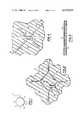
- FIG. 6is a perspective-exploded view of the coupler of the present invention enclosed within a waveguide housing.
- FIG. 1there is illustrated a schematic diagram of the reverse phased ring coupler of the present invention.
- the reverse phase ring coupler 12 of the present inventionhas all four arms 14, 16, 18 and 20 equal to one-quarter wavelength at the midband operating frequency of the coupler.
- Arm 20 of the couplerincludes a mechanism for introducing a 180° phase reversal in a signal propagating through that arm as is illustrated in FIG. 1 wherein the phase reversal segment is indicated by an X,22. Because the reverse phased ring is symmetrical, i.e. the two path lengths to the isolated port are exactly equal at all frequencies, the isolation is infinite at all frequencies and the power split does not vary.
- the deviceoperates such that an input signal applied to input-output port 1 will be divided equally between input-output ports 2 and 4 and will be isolated from input-output port 3. Similarly, an input signal may be applied to any of the ports, 1, 2, 3 or 4 and it will be divided equally between adjacent ports and isolated from the opposite port.
- the hybrid ring coupler 12 of the present inventionhas been illustrated in FIG. 1 as having a generally circular configuration, other shapes and configurations for the ring coupler are considered to be within scope of the present invention. Particularly, as will be described with respect to the embodiment of the present invention illustrated in FIG. 2, the coupler of the present invention may have a square configuration or any other configuration that results in an equal electrical length for the arms 14, 16, 18 and 20 of the coupler.
- the coupler 12 of the present inventionis constructed on a dielectric substrate 24 on the surface of which is placed a layer of metal foil 26.
- the metal foil 26is preferably copper that is applied to the dielectric substrate by any suitable technique.
- the dielectric substrate 24is, for instance, a laminate or Teflon impregnated fiber board.
- the arms 14, 16, 18 and 20are slotline transmission lines formed by etching away the metal layer 26, by photolithography or by any other suitable technique. Energy propagation in the slotline transmission arms 14, 16, 18 and 20 consists of electromagnetic fields in the slots formed between the areas of conductor 26.
- the input-output ports 1, 2, 3 and 4are also illustrated in FIG. 2 as slotline transmission lines.
- the arm 20is split at area 28 such that there are two sections of the arm 20, namely, section 20a and section 20b.
- a first quarter wave shorted slotline 30is connected to the inner end of the section of arm 20a and a second quarter wave shorted slotline 32 is connected to the inner end of the section of arm 20b.
- the quarter wave shorted slotlines 30 and 32extend from the respective ends of arm sections 20a and 20b for a distance ⁇ /4 where ⁇ is the wavelength at the midband operating frequency of the coupler.
- a short conductive strap 34bridges the two-quarter wave shorted slotlines 30 and 32 and the strip of ground plane conductor 26a situated between the quarter wave shorted slotlines 30 and 32.
- the numerals 28 and 26arefer to the same region, the numeral 28 being used to indicate the region of separation between the section of arm 20a and the section of arm 20b, and the numeral 26a being used to indicate the presence of conductor 26 in the separation region 28.
- the strap 34is grounded to the conductive foil 26 at the ends of the strap 34 and is separated from the slotlines 30 and 32 and the section of conductor 26a by an air gap 36.
- the conductor strap 34in combination with the air gap 36 and the conductors 26 and 26a form or approximate a microstrip conductor. Further, the strap 34 serves as a slotline-to-microstrip transition from the slotline conductors 20a and 30.
- the strap 34serves as a slotline-to-microstrip transition from the slotline conductors 20b and 32. It should therefore be readily understood that the strap 34 serves as a slotline-to-microstrip-to-slotline transition between the slotline conductors 20a and 20b. Each slotline-to-microstrip transition creates a 90° phase shift in a signal propagating through it and, therefore, the strap 34, comprising two back-to-back such transitions, creates a 180° phase reversal in any signal propagating the arm 20 of the coupler 12 of the present invention.
- the slotline 32has a shape and position that is a mirror symmetry of the slotline 30.
- the two slotlinescome in close proximity in the area of the separation 28 and it is also seen that the strap 34 is connected to the metal surface 26 by solder or conductive epoxy.
- the strap 34is quite short (less than 0.01 inches) and can be assumed to have near zero phase length.
- the two back-to-back slotline-to-microstrip transitions formed by the strap 34therefore introduce approximately a 180° phase shift and the total phase shift from port 1 to port 2 of the device 12 is 270°.
- Signals from port 1arrive at port 3 via the two paths comprised of circuit arms 14, 16 and comprised of circuit arms 20, 18 and arrive at port 3 such that they 180° out of phase and are thereby canceled.
- FIG. 5there is illustrated in dotted lines an alternative embodiment of the present invention.
- a metallic strip 38is applied to the opposite or underside 40 of the dielectric substrate 24.
- This conductor 38illustrated also in phantom in FIG. 4, overlays the area of separation 28 of the stripline transmission sections 20a and 20b.
- the metallized region 38serves as a microstrip conductor in combination with the dielectric substrate 24 and the metallized surface 26.
- the conductor 38extends for a distance ⁇ /4 on both sides of the separation 28 such that the conductor 38 appears to be shorted.
- the slotline reverse phase coupler 12 of the present inventioncan be designed for any frequency by properly adjusting the length of the ring arms 14, 16, 18 and 20 to equal a quarter wavelength at the midband of the operating frequency of the device.
- the slotline medium of the present inventionis particularly well adapted to the millimeter wave frequencies becuase the slotline medium is easily matched by simple transition to the conventional rectangular waveguide operating in the TE 10 mode as is illustrated in FIG. 6 wherein the coupler 12 is illustrated in combination with slotline-to-waveguide transitions 40 and is further illustrated in exploded form, as being enclosed within a waveguide housing 42.
- the waveguide enclosed slotline coupler 12is less lossy and has a higher wavelength to line-width ratio. It is therefore will defined and suitable for use at higher frequencies.
Landscapes
- Waveguide Aerials (AREA)
Abstract
Description
Claims (11)
Priority Applications (1)
| Application Number | Priority Date | Filing Date | Title |
|---|---|---|---|
| US06/305,231US4419635A (en) | 1981-09-24 | 1981-09-24 | Slotline reverse-phased hybrid ring coupler |
Applications Claiming Priority (1)
| Application Number | Priority Date | Filing Date | Title |
|---|---|---|---|
| US06/305,231US4419635A (en) | 1981-09-24 | 1981-09-24 | Slotline reverse-phased hybrid ring coupler |
Publications (1)
| Publication Number | Publication Date |
|---|---|
| US4419635Atrue US4419635A (en) | 1983-12-06 |
Family
ID=23179915
Family Applications (1)
| Application Number | Title | Priority Date | Filing Date |
|---|---|---|---|
| US06/305,231Expired - Fee RelatedUS4419635A (en) | 1981-09-24 | 1981-09-24 | Slotline reverse-phased hybrid ring coupler |
Country Status (1)
| Country | Link |
|---|---|
| US (1) | US4419635A (en) |
Cited By (11)
| Publication number | Priority date | Publication date | Assignee | Title |
|---|---|---|---|---|
| US5570069A (en)* | 1994-05-02 | 1996-10-29 | E-Systems, Inc. | Broadband directional coupler |
| US5625328A (en)* | 1995-09-15 | 1997-04-29 | E-Systems, Inc. | Stripline directional coupler tolerant of substrate variations |
| US5903827A (en)* | 1995-07-07 | 1999-05-11 | Fujitsu Compound Semiconductor, Inc. | Single balanced frequency downconverter for direct broadcast satellite transmissions and hybrid ring signal combiner |
| WO2000001030A1 (en)* | 1998-06-26 | 2000-01-06 | Racal Antennas Limited | Signal coupling methods and arrangements |
| EP1209756A1 (en)* | 2000-11-28 | 2002-05-29 | Telefonaktiebolaget L M Ericsson (Publ) | A radio frequency amplifying circuit |
| WO2002045206A1 (en)* | 2000-11-28 | 2002-06-06 | Telefonaktiebolaget Lm Ericsson (Publ) | A radio frequency amplifying circuit |
| US20030045262A1 (en)* | 2001-09-04 | 2003-03-06 | Vaughan Mark J. | Waveguide mixer/coupler |
| US20070236402A1 (en)* | 2006-04-11 | 2007-10-11 | Chang Industry, Inc. | Antenna and associated method of propagating electromagnetic waves |
| WO2008055914A1 (en)* | 2006-11-09 | 2008-05-15 | Bouygues Telecom | Multiport coupling for supplying one or more antennae from mutually independent sources antenna and antenna system comprising said coupling |
| CN100547852C (en)* | 2005-03-16 | 2009-10-07 | 国际商业机器公司 | DC isolated inverter and ring hybrid coupler and method thereof |
| CN106980049A (en)* | 2017-03-27 | 2017-07-25 | 河南师范大学 | Fluid dielectric property minor variations detection means based on co-planar waveguide/line of rabbet joint line style |
Citations (4)
| Publication number | Priority date | Publication date | Assignee | Title |
|---|---|---|---|---|
| US3995239A (en)* | 1975-09-08 | 1976-11-30 | Rockwell International Corporation | Transition apparatus |
| US4023123A (en)* | 1975-02-03 | 1977-05-10 | The United States Of America As Represented By The Secretary Of The Navy | Microstrip reverse-phased hybrid ring coupler |
| DE2747871A1 (en)* | 1976-11-26 | 1979-05-03 | Philips Patentverwaltung | Wide band 180 degrees phase shifter - has interleaved half and quarter wavelength meanders, using intermediate switching diodes for wavelength mode selection |
| US4316160A (en)* | 1980-07-28 | 1982-02-16 | Motorola Inc. | Impedance transforming hybrid ring |
- 1981
- 1981-09-24USUS06/305,231patent/US4419635A/ennot_activeExpired - Fee Related
Patent Citations (4)
| Publication number | Priority date | Publication date | Assignee | Title |
|---|---|---|---|---|
| US4023123A (en)* | 1975-02-03 | 1977-05-10 | The United States Of America As Represented By The Secretary Of The Navy | Microstrip reverse-phased hybrid ring coupler |
| US3995239A (en)* | 1975-09-08 | 1976-11-30 | Rockwell International Corporation | Transition apparatus |
| DE2747871A1 (en)* | 1976-11-26 | 1979-05-03 | Philips Patentverwaltung | Wide band 180 degrees phase shifter - has interleaved half and quarter wavelength meanders, using intermediate switching diodes for wavelength mode selection |
| US4316160A (en)* | 1980-07-28 | 1982-02-16 | Motorola Inc. | Impedance transforming hybrid ring |
Non-Patent Citations (2)
| Title |
|---|
| Horton, Crossovers In Microstrip, Electronics Letters, Feb. 16, 1978, vol. 4, No. 4, pp. 110, 111.* |
| Horton, Crossovers In Microstrip, Electronics Letters, Feb. 16, 1978, vol.4, No. 4, pp. 110, 111. |
Cited By (18)
| Publication number | Priority date | Publication date | Assignee | Title |
|---|---|---|---|---|
| US5570069A (en)* | 1994-05-02 | 1996-10-29 | E-Systems, Inc. | Broadband directional coupler |
| US5903827A (en)* | 1995-07-07 | 1999-05-11 | Fujitsu Compound Semiconductor, Inc. | Single balanced frequency downconverter for direct broadcast satellite transmissions and hybrid ring signal combiner |
| US5625328A (en)* | 1995-09-15 | 1997-04-29 | E-Systems, Inc. | Stripline directional coupler tolerant of substrate variations |
| US20030137464A1 (en)* | 1998-06-26 | 2003-07-24 | Racal Antennas Limited | Signal coupling methods and arrangements |
| WO2000001030A1 (en)* | 1998-06-26 | 2000-01-06 | Racal Antennas Limited | Signal coupling methods and arrangements |
| EP1341258A1 (en)* | 1998-06-26 | 2003-09-03 | Thales Antennas Limited | Signal coupling methods and arrangements |
| US6509883B1 (en) | 1998-06-26 | 2003-01-21 | Racal Antennas Limited | Signal coupling methods and arrangements |
| EP1209756A1 (en)* | 2000-11-28 | 2002-05-29 | Telefonaktiebolaget L M Ericsson (Publ) | A radio frequency amplifying circuit |
| WO2002045206A1 (en)* | 2000-11-28 | 2002-06-06 | Telefonaktiebolaget Lm Ericsson (Publ) | A radio frequency amplifying circuit |
| US6794953B2 (en) | 2000-11-28 | 2004-09-21 | Telefonaktiebolaget Lm Ericsson (Publ) | Radio frequency amplifying circuit |
| US20030045262A1 (en)* | 2001-09-04 | 2003-03-06 | Vaughan Mark J. | Waveguide mixer/coupler |
| CN100547852C (en)* | 2005-03-16 | 2009-10-07 | 国际商业机器公司 | DC isolated inverter and ring hybrid coupler and method thereof |
| US20070236402A1 (en)* | 2006-04-11 | 2007-10-11 | Chang Industry, Inc. | Antenna and associated method of propagating electromagnetic waves |
| US7453410B2 (en) | 2006-04-11 | 2008-11-18 | Chang Indusatry, Inc. | Waveguide antenna using a continuous loop waveguide feed and method of propagating electromagnetic waves |
| WO2008055914A1 (en)* | 2006-11-09 | 2008-05-15 | Bouygues Telecom | Multiport coupling for supplying one or more antennae from mutually independent sources antenna and antenna system comprising said coupling |
| FR2908559A1 (en)* | 2006-11-09 | 2008-05-16 | Bouygues Telecom Sa | MULTI-PORT COUPLER FOR THE POWER SUPPLY OF ONE OR MORE ANTENNAS BY SINGLE SOURCES FROM ONE TO THE OTHER, ANTENNA AND ANTENNA SYSTEM INTEGRATING THE COUPLER |
| CN106980049A (en)* | 2017-03-27 | 2017-07-25 | 河南师范大学 | Fluid dielectric property minor variations detection means based on co-planar waveguide/line of rabbet joint line style |
| CN106980049B (en)* | 2017-03-27 | 2023-03-07 | 河南师范大学 | Fluid dielectric property tiny change detection device based on coplanar waveguide/slot line type |
Similar Documents
| Publication | Publication Date | Title |
|---|---|---|
| US3560893A (en) | Surface strip transmission line and microwave devices using same | |
| US3579149A (en) | Waveguide to stripline transition means | |
| US4902992A (en) | Millimeter-wave multiplexers | |
| US5075646A (en) | Compensated mixed dielectric overlay coupler | |
| US4419635A (en) | Slotline reverse-phased hybrid ring coupler | |
| US4150345A (en) | Microstrip coupler having increased coupling area | |
| US5097233A (en) | Coplanar 3dB quadrature coupler | |
| US6087907A (en) | Transverse electric or quasi-transverse electric mode to waveguide mode transformer | |
| US3946339A (en) | Slot line/microstrip hybrid | |
| US4578652A (en) | Broadband four-port TEM mode 180° printed circuit microwave hybrid | |
| US4023123A (en) | Microstrip reverse-phased hybrid ring coupler | |
| US4331942A (en) | Stripline diode phase shifter | |
| EP1346432B1 (en) | Four port hybrid microstrip circuit of lange type | |
| US3721921A (en) | Waveguide directional coupler | |
| US3611153A (en) | Balanced mixer utilizing strip transmission line hybrid | |
| KR930004493B1 (en) | Planer Air Stripline-Stripline Magic-T Network Device | |
| US3715689A (en) | Wideband microwave power divider | |
| US4749969A (en) | 180° hybrid tee | |
| US4427953A (en) | Microwave diplexer | |
| US2749519A (en) | Directional couplers for microwave transmission systems | |
| US3848198A (en) | Microwave transmission line and devices using multiple coplanar conductors | |
| US3560887A (en) | Directional filter comprising a resonant loop coupled to a transmission line pair | |
| US4093928A (en) | Microstrip hybrid ring coupler | |
| US3497832A (en) | Radio frequency transmission line tee hybrid | |
| US5426400A (en) | Broadband coplanar waveguide to slotline transition having a slot cavity |
Legal Events
| Date | Code | Title | Description |
|---|---|---|---|
| AS | Assignment | Owner name:UNITED STATES OF AMERICA AS REPRESENTED BY THE SEC Free format text:ASSIGNMENT OF ASSIGNORS INTEREST.;ASSIGNOR:REINDEL, JOHN;REEL/FRAME:003930/0568 Effective date:19810911 Owner name:UNITED STATES OF AMERICA AS REPRESENTED BY THE SEC Free format text:ASSIGNMENT OF ASSIGNORS INTEREST;ASSIGNOR:REINDEL, JOHN;REEL/FRAME:003930/0568 Effective date:19810911 | |
| FEPP | Fee payment procedure | Free format text:SURCHARGE FOR LATE PAYMENT, PL 96-517 (ORIGINAL EVENT CODE: M176); ENTITY STATUS OF PATENT OWNER: LARGE ENTITY | |
| MAFP | Maintenance fee payment | Free format text:PAYMENT OF MAINTENANCE FEE, 4TH YEAR, PL 96-517 (ORIGINAL EVENT CODE: M170); ENTITY STATUS OF PATENT OWNER: LARGE ENTITY Year of fee payment:4 | |
| FEPP | Fee payment procedure | Free format text:MAINTENANCE FEE REMINDER MAILED (ORIGINAL EVENT CODE: REM.); ENTITY STATUS OF PATENT OWNER: LARGE ENTITY | |
| LAPS | Lapse for failure to pay maintenance fees | ||
| FP | Lapsed due to failure to pay maintenance fee | Effective date:19911208 | |
| STCH | Information on status: patent discontinuation | Free format text:PATENT EXPIRED DUE TO NONPAYMENT OF MAINTENANCE FEES UNDER 37 CFR 1.362 |