US4419562A - Nondestructive real-time method for monitoring the quality of a weld - Google Patents
Nondestructive real-time method for monitoring the quality of a weldDownload PDFInfo
- Publication number
- US4419562A US4419562AUS06/340,607US34060782AUS4419562AUS 4419562 AUS4419562 AUS 4419562AUS 34060782 AUS34060782 AUS 34060782AUS 4419562 AUS4419562 AUS 4419562A
- Authority
- US
- United States
- Prior art keywords
- weld
- workpiece
- quality
- acoustic emission
- monitoring
- Prior art date
- Legal status (The legal status is an assumption and is not a legal conclusion. Google has not performed a legal analysis and makes no representation as to the accuracy of the status listed.)
- Expired - Lifetime
Links
Images


Classifications
- B—PERFORMING OPERATIONS; TRANSPORTING
- B23—MACHINE TOOLS; METAL-WORKING NOT OTHERWISE PROVIDED FOR
- B23K—SOLDERING OR UNSOLDERING; WELDING; CLADDING OR PLATING BY SOLDERING OR WELDING; CUTTING BY APPLYING HEAT LOCALLY, e.g. FLAME CUTTING; WORKING BY LASER BEAM
- B23K15/00—Electron-beam welding or cutting
- B23K15/0013—Positioning or observing workpieces, e.g. with respect to the impact; Aligning, aiming or focusing electronbeams
- B—PERFORMING OPERATIONS; TRANSPORTING
- B23—MACHINE TOOLS; METAL-WORKING NOT OTHERWISE PROVIDED FOR
- B23K—SOLDERING OR UNSOLDERING; WELDING; CLADDING OR PLATING BY SOLDERING OR WELDING; CUTTING BY APPLYING HEAT LOCALLY, e.g. FLAME CUTTING; WORKING BY LASER BEAM
- B23K26/00—Working by laser beam, e.g. welding, cutting or boring
- B23K26/02—Positioning or observing the workpiece, e.g. with respect to the point of impact; Aligning, aiming or focusing the laser beam
- B23K26/03—Observing, e.g. monitoring, the workpiece
- B—PERFORMING OPERATIONS; TRANSPORTING
- B23—MACHINE TOOLS; METAL-WORKING NOT OTHERWISE PROVIDED FOR
- B23K—SOLDERING OR UNSOLDERING; WELDING; CLADDING OR PLATING BY SOLDERING OR WELDING; CUTTING BY APPLYING HEAT LOCALLY, e.g. FLAME CUTTING; WORKING BY LASER BEAM
- B23K37/00—Auxiliary devices or processes, not specially adapted for a procedure covered by only one of the other main groups of this subclass
Definitions
- the present inventionrelates to a method for monitoring the quality of a weld and more particularly to a noncontact nondestructive method for the real-time monitoring of laser welds using acoustic emission techniques.
- High energy welding techniquessuch as laser or electron beam welding, are capable of generating extremely localized high energy beams resulting in unique advantages when welding small workpieces or components.
- the integrity of such welding techniquesis determined by analyzing the resulting welds. Such analysis may vary from a mere visual inspection of the welded joint on the workpiece to a detailed post-welding X-ray, ultrasonic, or infrared examination of the welded workpiece or component. Often, destructive methods are used to evaluate the joining technique by testing samples, rather than all, of the components produced.
- the present inventionsolves the foregoing problems with a method for monitoring the quality of a weld on a workpiece comprising the steps of positioning a high frequency acoustic sensor in noncontact spaced relation with the workpiece and in noncontact spaced relation with the weld site on the workpiece; detecting at the acoustic sensor airborne acoustic signals generated at the weld site; and analyzing the detected airborne acoustic signals thereby determining the quality of the weld.
- One advantage of the present inventionis the elimination of any direct mounting of the acoustic sensor on the workpiece or component being welded.
- Another advantage of the present inventionis the ability to monitor the quality of a weld without requiring the mounting of the acoustic sensor on the workpiece holder.
- a further advantage of the present inventionis the ability to achieve a reliable evaluation of the quality of a weld on the workpiece regardless of the complexity or topography of the workpiece holder.
- a still further advantage of the present inventionis the ability to maintain the acoustic sensor at a predetermined distance from the weld site thereby enabling an accurate monitoring of the quality of a laser weld.
- FIG. 1is a schematic representation of an airborne acoustic emission detection system in accordance with the present invention
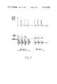
- FIG. 2is a wave diagram relating to the embodiment shown in FIG. 1;
- FIG. 3is a partial block diagram of an on-line acoustic emission laser weld monitoring system incorporating the present inventive concepts.
- FIG. 1Schematically shown in FIG. 1 is an arrangement for implementing the weld monitoring method in accordance with an illustrative embodiment of the present invention.
- Workpiece 1 to be weldedis placed on a receiving base 2 such that the intended weld site 3 on the workpiece 1 is exposed to a high energy welding source 4.
- the lattermay be for example a laser beam source or any other high energy source suitable for welding operations.
- the following descriptionrefers to a laser beam welding technique.
- welding source 4generates a high energy laser beam 5 directed toward the weld site 3 of workpiece 1.
- a metal plate 6attached to a mounting arm 7 which in turn is slidably coupled to a mounting bracket 8 fixed to welding source 4.
- the coupling between plate 6, arm 7 and bracket 8is such that the distance between plate 6 and workpiece 1 can be selectively varied by moving the arm 7 with respect to the bracket 8.
- plate 6has an aperture 9 for enabling the passage of laser beam 5 towards the weld site 3 of the workpiece.
- the impact of the laser beam 5 on the workpiece 1results in the generation of airborne acoustic emission signals illustratively shown by reference numeral 10.
- airborne acoustic emission signalsillustratively shown by reference numeral 10.
- airborne signalspropagate away from the workpiece 1 through the air space between the workpiece and the metal plate 6.
- the airborne AE signals 10impact the latter on its back surface 11 and cause the generation of signals within the plate.
- These generated signalsare detected by means of a high frequency acoustic sensor 12 attached to the plate 6.
- sensor 12is shown attached to the upper surface of plate 6, the present arrangement will also operate with sensor 12 attached to the back surface 11 of plate 6.
- the analysis by an AE signal analyzer (not shown) of the detected signalsenables a determination of the quality of the weld being performed at weld site 3.
- a possible explanation for the generation of the airborne AE signalsmay be summarized as follows: as the result of the impact between incoming laser beam 5 and the surface of the solid metallic workpiece 1, a metallic liquid formation takes place at the weld site 3. Due to the high temperature of the liquid formation, vaporization and plume formation follow. The interaction between the incoming laser beam 5 and the plume generates an air shock wave which propagates away from the weld site 3 towards the back surface 11 of the plate 6. Such an airborne wave impacts the plate 6 causing acoustic emission signals being generated therein. Therefore, there exists a correlation between the quality of the weld at the weld site 3 and the airborne AE signals 10 detected by the high frequency acoustic sensor 12.
- FIG. 2Shown in FIG. 2 is a series of n+1 welding laser pulses, wherein each one of the laser pulses impinges upon the workpiece to be welded. Also shown is an equal number of acoustic emission signals AE 1 to AE n+1 generated in response to the incoming laser pulses. As long as a good laser coupling exists between the welding beam and the welded material, the acoustic emission signals have an amplitude above a predetermined threshold level, AE threshold .
- the corresponding acoustic emission signals AE n-1 , AE n and AE n+1exhibit an amplitude lower than that of the threshold level when a poor laser coupling exists between the welding beam and the welded material resulting in bad welds.
- the acoustic emission threshold levelis set at a value above the noise level of the electronic circuitry used in the AE signal analyzer. Such AE threshold level will typically be of the order of 500 mV.
- FIG. 3Shown in FIG. 3 is an acoustic emission laser weld monitoring system implementing an on-line real-time analysis of laser welds.
- a plurality of pieceparts to be welded 21, 22, 23, 24are fed on a conveying arrangement 25 such that each piecepart is sequentially exposed to a laser welding beam 26 generated by a laser source 27.
- a mounting bracket 28is attached to laser source 27.
- a metal plate 29, having an aperture 30 to enable the passage of laser beam 26 therethrough,is slidably coupled to the bracket 28 by means of coupling arm 31.
- a high frequency acoustic sensor 32is attached to metal plate 29 for detecting the airborne acoustic signals 33 generated at the respective weld sites, e.g., 34 on piecepart 22.
- sensor 32may be attached to either surface of metal plate 29 without departing from the spirit and scope of the present invention.
- the high frequency acoustic sensor 32generates low level signals on its output lead 35 in response to the airborne acoustic signals 33.
- the low level signals on lead 35are amplified by a low noise preamplifier 36, the output of which is coupled to an acoustic emission signal analyzer 37 of a generally known type.
- AE analyzer 37includes, for example, a threshold detector circuit for discriminating between high and low amplitude AE signals respectively corresponding to a good quality laser weld and a poor quality laser weld.
- the output terminal of AE analyzer 37is coupled to an output monitoring device 38.
- Such output devicemay be a printer, a CRT display device, an audio alarm system, or any other well known interface information system capable of controlling the welding operations performed on the various pieceparts 21 to 24.
- the output of AE analyzer 37is also coupled via lead 39 to a rejection marking arrangement 40 capable of marking, after the welding operation, any one of the welded pieceparts comprising a bad or defective weld.
- a rejection marking arrangement 40capable of marking, after the welding operation, any one of the welded pieceparts comprising a bad or defective weld.
- marking operationis schematically illustrated by mechanical linkage 41 which may include a stamping, labelling or other identification technique, for marking a defective welded piecepart.
- the high energy welding source 4 and 27may be a commercially available CO 2 laser capable of being repetitively fired thereby generating successive laser beams resulting in contiguous melting zones on the piecepart being welded.
- metal plates 6 in FIG. 1 and 29 in FIG. 3are steel plates of about 3 inches by 3 inches with a thickness of about 0.1 inch respectively having apertures 9 and 30 of about 0.5 inch in diameter.
- Acoustic sensors 12 and 32are preferably wideband piezoelectric transducers of commercially available type, and have a frequency response above 100 kltz.
- steel plates 6 and 29have a well finished back surface (i.e., the surface facing the workpiece being welded) to achieve a good coupling between the airborne acoustic signals 10 and 33 and the respective acoustic sensors 12 and 32.
Landscapes
- Engineering & Computer Science (AREA)
- Physics & Mathematics (AREA)
- Optics & Photonics (AREA)
- Mechanical Engineering (AREA)
- Plasma & Fusion (AREA)
- Investigating Or Analyzing Materials By The Use Of Ultrasonic Waves (AREA)
Abstract
Description
Claims (4)
Priority Applications (1)
| Application Number | Priority Date | Filing Date | Title |
|---|---|---|---|
| US06/340,607US4419562A (en) | 1982-01-19 | 1982-01-19 | Nondestructive real-time method for monitoring the quality of a weld |
Applications Claiming Priority (1)
| Application Number | Priority Date | Filing Date | Title |
|---|---|---|---|
| US06/340,607US4419562A (en) | 1982-01-19 | 1982-01-19 | Nondestructive real-time method for monitoring the quality of a weld |
Publications (1)
| Publication Number | Publication Date |
|---|---|
| US4419562Atrue US4419562A (en) | 1983-12-06 |
Family
ID=23334145
Family Applications (1)
| Application Number | Title | Priority Date | Filing Date |
|---|---|---|---|
| US06/340,607Expired - LifetimeUS4419562A (en) | 1982-01-19 | 1982-01-19 | Nondestructive real-time method for monitoring the quality of a weld |
Country Status (1)
| Country | Link |
|---|---|
| US (1) | US4419562A (en) |
Cited By (54)
| Publication number | Priority date | Publication date | Assignee | Title |
|---|---|---|---|---|
| US4504727A (en)* | 1982-12-30 | 1985-03-12 | International Business Machines Corporation | Laser drilling system utilizing photoacoustic feedback |
| US4555052A (en)* | 1983-02-28 | 1985-11-26 | Fairchild Camera & Instrument Corporation | Lead wire bond attempt detection |
| DE3435829A1 (en)* | 1984-09-28 | 1986-04-10 | Siemens AG, 1000 Berlin und 8000 München | SENSOR FOR MONITORING IN THE PRODUCTION OF WELDING SEAMS |
| US4633057A (en)* | 1985-08-22 | 1986-12-30 | Avco Corporation | Laser welder fault detector |
| US4712722A (en)* | 1985-09-04 | 1987-12-15 | Eg&G, Inc. | Concurrent ultrasonic weld evaluation system |
| US4940633A (en)* | 1989-05-26 | 1990-07-10 | Hermansen Ralph D | Method of bonding metals with a radio-opaque adhesive/sealant for void detection and product made |
| US4960970A (en)* | 1989-08-11 | 1990-10-02 | General Electric Company | Method and apparatus for acoustic breakthrough detection |
| DE3913786A1 (en)* | 1989-04-26 | 1990-10-31 | Siemens Ag | Contact-free monitoring sonic emission - from workpieces during high energy beam working, using plate transparent to high energy beam attached to sonic sensor |
| US5121339A (en)* | 1990-08-16 | 1992-06-09 | General Motors Corporation | Laser weld fault detection system |
| US5155328A (en)* | 1990-08-07 | 1992-10-13 | Amada Company, Limited | Device for detecting cutting states in laser beam machining |
| US5170929A (en)* | 1992-05-29 | 1992-12-15 | International Business Machines Corporation | Ultrasonic adhesion/dehesion monitoring apparatus with acoustic transducer means |
| US5194723A (en)* | 1991-12-24 | 1993-03-16 | Maxwell Laboratories, Inc. | Photoacoustic control of a pulsed light material removal process |
| US5204517A (en)* | 1991-12-24 | 1993-04-20 | Maxwell Laboratories, Inc. | Method and system for control of a material removal process using spectral emission discrimination |
| US5221825A (en)* | 1992-06-01 | 1993-06-22 | The United States Of America As Represented By The Secretary Of Commerce | Sensing of gas metal arc welding process characteristics for welding process control |
| US5281798A (en)* | 1991-12-24 | 1994-01-25 | Maxwell Laboratories, Inc. | Method and system for selective removal of material coating from a substrate using a flashlamp |
| US5328517A (en)* | 1991-12-24 | 1994-07-12 | Mcdonnell Douglas Corporation | Method and system for removing a coating from a substrate using radiant energy and a particle stream |
| US5512123A (en)* | 1992-05-19 | 1996-04-30 | Maxwell Laboratories | Method for using pulsed optical energy to increase the bondability of a surface |
| US5571335A (en)* | 1991-12-12 | 1996-11-05 | Cold Jet, Inc. | Method for removal of surface coatings |
| US5613509A (en)* | 1991-12-24 | 1997-03-25 | Maxwell Laboratories, Inc. | Method and apparatus for removing contaminants and coatings from a substrate using pulsed radiant energy and liquid carbon dioxide |
| US5782253A (en)* | 1991-12-24 | 1998-07-21 | Mcdonnell Douglas Corporation | System for removing a coating from a substrate |
| US6670574B1 (en) | 2002-07-31 | 2003-12-30 | Unitek Miyachi Corporation | Laser weld monitor |
| US20040224618A1 (en)* | 2000-09-08 | 2004-11-11 | Rivir Michael E. | Particle blast apparatus |
| WO2006089257A1 (en)* | 2005-02-17 | 2006-08-24 | The Regents Of The University Of California | Strength measurement of solder joints using laser generated stress waves |
| US20070090098A1 (en)* | 2005-10-20 | 2007-04-26 | Denso Corporation | Abnormality determination and estimation method, and abnormality determination and estimation device for weld product |
| EP1335423A3 (en)* | 2002-02-08 | 2008-08-13 | Sagem Orga GmbH | Method of detection of damages on integrated circuit devices |
| US20090173721A1 (en)* | 2006-03-10 | 2009-07-09 | Kouji Ueoka | Method and apparatus for welding electrode collectors and terminals of electrical storage element |
| WO2011026638A1 (en)* | 2009-09-04 | 2011-03-10 | Precitec Kg | Method for classifying a laser process and a laser material processing head using the same |
| US20110284508A1 (en)* | 2010-05-21 | 2011-11-24 | Kabushiki Kaisha Toshiba | Welding system and welding method |
| US20140255620A1 (en)* | 2013-03-06 | 2014-09-11 | Rolls-Royce Corporation | Sonic grain refinement of laser deposits |
| US20150069112A1 (en)* | 2013-09-12 | 2015-03-12 | Ford Global Technologies, Llc | Non-destructive aluminum weld quality estimator |
| US9074927B2 (en) | 2012-10-16 | 2015-07-07 | Honeywell International Inc. | Methods for non-destructively evaluating a joined component |
| US9217731B2 (en) | 2010-05-21 | 2015-12-22 | Kabushiki Kaisha Toshiba | Welding inspection method and apparatus thereof |
| RU2572067C1 (en)* | 2014-08-06 | 2015-12-27 | Федеральное государственное бюджетное образовательное учреждение высшего профессионального образования "Сибирский государственный университет путей сообщения" (СГУПС) | Method of acoustic emission quality control of girth weld during multipass welding and device for its implementation |
| CN105921854A (en)* | 2016-05-04 | 2016-09-07 | 江苏科技大学 | Rotating arc narrow-gap MAG welding line deviation recognition device and method |
| US20170068266A1 (en)* | 2015-09-03 | 2017-03-09 | Lincoln Global, Inc. | Power source system |
| GB2547434A (en)* | 2016-02-17 | 2017-08-23 | Rolls Royce Plc | Method of manufacture |
| EP3257615A1 (en) | 2016-06-15 | 2017-12-20 | Eidgenössische Materialprüfungs- und Forschungsanstalt EMPA | Quality control of laser welding process |
| US9937577B2 (en) | 2006-12-20 | 2018-04-10 | Lincoln Global, Inc. | System for a welding sequencer |
| US9989495B2 (en) | 2015-11-19 | 2018-06-05 | General Electric Company | Acoustic monitoring method for additive manufacturing processes |
| US9989396B2 (en) | 2015-11-20 | 2018-06-05 | General Electric Company | Gas flow characterization in additive manufacturing |
| US10073060B2 (en) | 2015-11-19 | 2018-09-11 | General Electric Company | Non-contact acoustic inspection method for additive manufacturing processes |
| RU186330U1 (en)* | 2018-04-16 | 2019-01-16 | Федеральное государственное бюджетное образовательное учреждение высшего образования "Самарский государственный университет путей сообщения" (СамГУПС) | Multichannel device for acoustic emission diagnostics of metal structures |
| US10232439B2 (en) | 2015-11-20 | 2019-03-19 | General Electric Company | Gas flow monitoring in additive manufacturing |
| US20190091810A1 (en)* | 2013-05-10 | 2019-03-28 | Illinois Tool Works Inc. | Data acquisition using a purge plug |
| US20190271669A1 (en)* | 2018-03-01 | 2019-09-05 | Battelle Memorial Institute | Characterization of ultrasonic consolidation bond quality |
| US10416701B2 (en) | 2015-09-03 | 2019-09-17 | Lincoln Global, Inc. | Systems and methods of controlling a maximum power output level of an engine-driven power source system |
| US10496080B2 (en) | 2006-12-20 | 2019-12-03 | Lincoln Global, Inc. | Welding job sequencer |
| RU2712659C1 (en)* | 2019-05-22 | 2020-01-31 | Федеральное государственное бюджетное образовательное учреждение высшего образования "Сибирский государственный университет путей сообщения" (СГУПС) | Method of acoustic emission control of quality of annular weld during multipass welding |
| US10639742B2 (en) | 2015-12-18 | 2020-05-05 | Rolls-Royce Corporation | Vessel for joining materials |
| US10994358B2 (en) | 2006-12-20 | 2021-05-04 | Lincoln Global, Inc. | System and method for creating or modifying a welding sequence based on non-real world weld data |
| US10994357B2 (en) | 2006-12-20 | 2021-05-04 | Lincoln Global, Inc. | System and method for creating or modifying a welding sequence |
| US11072034B2 (en) | 2006-12-20 | 2021-07-27 | Lincoln Global, Inc. | System and method of exporting or using welding sequencer data for external systems |
| US11396061B2 (en)* | 2018-12-21 | 2022-07-26 | Panasonic Intellectual Property Management Co., Ltd. | Laser welding apparatus and laser welding method |
| US20230294214A1 (en)* | 2022-03-18 | 2023-09-21 | Kabushiki Kaisha Toshiba | Ultrasonic welding diagnostic method, joining method of welding member, and inspection device |
Citations (7)
| Publication number | Priority date | Publication date | Assignee | Title |
|---|---|---|---|---|
| US3648009A (en)* | 1969-05-06 | 1972-03-07 | Karl Heinz Steigerwald | Method and device for inspecting and/or controlling thermally produced mechanical joints |
| US3679865A (en)* | 1969-04-15 | 1972-07-25 | Redemat Sa | Apparatus for controlling electric welding processes |
| US3824377A (en)* | 1972-05-10 | 1974-07-16 | Trodyne Corp | Acoustic emission spot welding controller |
| GB1430824A (en)* | 1972-07-27 | 1976-04-07 | Mitsui Shipbuilding Eng | Welding control method by welding sound |
| US3986391A (en)* | 1975-09-22 | 1976-10-19 | Western Electric Company, Inc. | Method and apparatus for the real-time monitoring of a continuous weld using stress-wave emission techniques |
| US4007631A (en)* | 1975-08-18 | 1977-02-15 | Western Electric Company, Inc. | Method and apparatus for evaluating welds using stress-wave emission techniques |
| US4144766A (en)* | 1977-05-02 | 1979-03-20 | The Babcock & Wilcox Company | Apparatus for the in-situ detection and location of flaws in welds |
- 1982
- 1982-01-19USUS06/340,607patent/US4419562A/ennot_activeExpired - Lifetime
Patent Citations (7)
| Publication number | Priority date | Publication date | Assignee | Title |
|---|---|---|---|---|
| US3679865A (en)* | 1969-04-15 | 1972-07-25 | Redemat Sa | Apparatus for controlling electric welding processes |
| US3648009A (en)* | 1969-05-06 | 1972-03-07 | Karl Heinz Steigerwald | Method and device for inspecting and/or controlling thermally produced mechanical joints |
| US3824377A (en)* | 1972-05-10 | 1974-07-16 | Trodyne Corp | Acoustic emission spot welding controller |
| GB1430824A (en)* | 1972-07-27 | 1976-04-07 | Mitsui Shipbuilding Eng | Welding control method by welding sound |
| US4007631A (en)* | 1975-08-18 | 1977-02-15 | Western Electric Company, Inc. | Method and apparatus for evaluating welds using stress-wave emission techniques |
| US3986391A (en)* | 1975-09-22 | 1976-10-19 | Western Electric Company, Inc. | Method and apparatus for the real-time monitoring of a continuous weld using stress-wave emission techniques |
| US4144766A (en)* | 1977-05-02 | 1979-03-20 | The Babcock & Wilcox Company | Apparatus for the in-situ detection and location of flaws in welds |
Non-Patent Citations (2)
| Title |
|---|
| G. T. Mallick, Jr., "Acoustic Die Monitoring", S.M.E. Technical Paper TE77-502, 1977, pp. 1-15.* |
| R. E. Herzog, "Forecasting Failures with Acoustic Emission", Machine Design, vol. 45, 6/14/73, pp. 132-137.* |
Cited By (69)
| Publication number | Priority date | Publication date | Assignee | Title |
|---|---|---|---|---|
| US4504727A (en)* | 1982-12-30 | 1985-03-12 | International Business Machines Corporation | Laser drilling system utilizing photoacoustic feedback |
| US4555052A (en)* | 1983-02-28 | 1985-11-26 | Fairchild Camera & Instrument Corporation | Lead wire bond attempt detection |
| DE3435829A1 (en)* | 1984-09-28 | 1986-04-10 | Siemens AG, 1000 Berlin und 8000 München | SENSOR FOR MONITORING IN THE PRODUCTION OF WELDING SEAMS |
| US4650958A (en)* | 1984-09-28 | 1987-03-17 | Siemens Aktiengesellschaft | Monitoring sensor for the production of welds |
| US4633057A (en)* | 1985-08-22 | 1986-12-30 | Avco Corporation | Laser welder fault detector |
| US4712722A (en)* | 1985-09-04 | 1987-12-15 | Eg&G, Inc. | Concurrent ultrasonic weld evaluation system |
| DE3913786A1 (en)* | 1989-04-26 | 1990-10-31 | Siemens Ag | Contact-free monitoring sonic emission - from workpieces during high energy beam working, using plate transparent to high energy beam attached to sonic sensor |
| US4940633A (en)* | 1989-05-26 | 1990-07-10 | Hermansen Ralph D | Method of bonding metals with a radio-opaque adhesive/sealant for void detection and product made |
| US4960970A (en)* | 1989-08-11 | 1990-10-02 | General Electric Company | Method and apparatus for acoustic breakthrough detection |
| US5155328A (en)* | 1990-08-07 | 1992-10-13 | Amada Company, Limited | Device for detecting cutting states in laser beam machining |
| US5121339A (en)* | 1990-08-16 | 1992-06-09 | General Motors Corporation | Laser weld fault detection system |
| US5571335A (en)* | 1991-12-12 | 1996-11-05 | Cold Jet, Inc. | Method for removal of surface coatings |
| US5782253A (en)* | 1991-12-24 | 1998-07-21 | Mcdonnell Douglas Corporation | System for removing a coating from a substrate |
| US5281798A (en)* | 1991-12-24 | 1994-01-25 | Maxwell Laboratories, Inc. | Method and system for selective removal of material coating from a substrate using a flashlamp |
| US5328517A (en)* | 1991-12-24 | 1994-07-12 | Mcdonnell Douglas Corporation | Method and system for removing a coating from a substrate using radiant energy and a particle stream |
| US5194723A (en)* | 1991-12-24 | 1993-03-16 | Maxwell Laboratories, Inc. | Photoacoustic control of a pulsed light material removal process |
| US5613509A (en)* | 1991-12-24 | 1997-03-25 | Maxwell Laboratories, Inc. | Method and apparatus for removing contaminants and coatings from a substrate using pulsed radiant energy and liquid carbon dioxide |
| US5204517A (en)* | 1991-12-24 | 1993-04-20 | Maxwell Laboratories, Inc. | Method and system for control of a material removal process using spectral emission discrimination |
| US5512123A (en)* | 1992-05-19 | 1996-04-30 | Maxwell Laboratories | Method for using pulsed optical energy to increase the bondability of a surface |
| US5170929A (en)* | 1992-05-29 | 1992-12-15 | International Business Machines Corporation | Ultrasonic adhesion/dehesion monitoring apparatus with acoustic transducer means |
| US5221825A (en)* | 1992-06-01 | 1993-06-22 | The United States Of America As Represented By The Secretary Of Commerce | Sensing of gas metal arc welding process characteristics for welding process control |
| US20040224618A1 (en)* | 2000-09-08 | 2004-11-11 | Rivir Michael E. | Particle blast apparatus |
| US7950984B2 (en) | 2000-09-08 | 2011-05-31 | Cold Jet, Inc. | Particle blast apparatus |
| EP1335423A3 (en)* | 2002-02-08 | 2008-08-13 | Sagem Orga GmbH | Method of detection of damages on integrated circuit devices |
| US20040069754A1 (en)* | 2002-07-31 | 2004-04-15 | Gregory Bates | Laser weld Monitor |
| US7129438B2 (en) | 2002-07-31 | 2006-10-31 | Miyachi Unitek Corporation | Laser weld monitor |
| US6670574B1 (en) | 2002-07-31 | 2003-12-30 | Unitek Miyachi Corporation | Laser weld monitor |
| US20080212067A1 (en)* | 2005-02-17 | 2008-09-04 | The Regents Of The University Of California | Inspection and strength measurement of solder and structural joints using laser generated stress waves |
| WO2006089257A1 (en)* | 2005-02-17 | 2006-08-24 | The Regents Of The University Of California | Strength measurement of solder joints using laser generated stress waves |
| US20070090098A1 (en)* | 2005-10-20 | 2007-04-26 | Denso Corporation | Abnormality determination and estimation method, and abnormality determination and estimation device for weld product |
| US7939780B2 (en)* | 2005-10-20 | 2011-05-10 | Denso Corporation | Abnormality determination and estimation method, and abnormality determination and estimation device for weld product |
| US20090173721A1 (en)* | 2006-03-10 | 2009-07-09 | Kouji Ueoka | Method and apparatus for welding electrode collectors and terminals of electrical storage element |
| US9937577B2 (en) | 2006-12-20 | 2018-04-10 | Lincoln Global, Inc. | System for a welding sequencer |
| US11980976B2 (en) | 2006-12-20 | 2024-05-14 | Lincoln Global, Inc. | Method for a welding sequencer |
| US11072034B2 (en) | 2006-12-20 | 2021-07-27 | Lincoln Global, Inc. | System and method of exporting or using welding sequencer data for external systems |
| US10994357B2 (en) | 2006-12-20 | 2021-05-04 | Lincoln Global, Inc. | System and method for creating or modifying a welding sequence |
| US10994358B2 (en) | 2006-12-20 | 2021-05-04 | Lincoln Global, Inc. | System and method for creating or modifying a welding sequence based on non-real world weld data |
| US10940555B2 (en) | 2006-12-20 | 2021-03-09 | Lincoln Global, Inc. | System for a welding sequencer |
| US10496080B2 (en) | 2006-12-20 | 2019-12-03 | Lincoln Global, Inc. | Welding job sequencer |
| WO2011026638A1 (en)* | 2009-09-04 | 2011-03-10 | Precitec Kg | Method for classifying a laser process and a laser material processing head using the same |
| US20110284508A1 (en)* | 2010-05-21 | 2011-11-24 | Kabushiki Kaisha Toshiba | Welding system and welding method |
| US9217731B2 (en) | 2010-05-21 | 2015-12-22 | Kabushiki Kaisha Toshiba | Welding inspection method and apparatus thereof |
| US9074927B2 (en) | 2012-10-16 | 2015-07-07 | Honeywell International Inc. | Methods for non-destructively evaluating a joined component |
| US20140255620A1 (en)* | 2013-03-06 | 2014-09-11 | Rolls-Royce Corporation | Sonic grain refinement of laser deposits |
| US20190091810A1 (en)* | 2013-05-10 | 2019-03-28 | Illinois Tool Works Inc. | Data acquisition using a purge plug |
| US20150069112A1 (en)* | 2013-09-12 | 2015-03-12 | Ford Global Technologies, Llc | Non-destructive aluminum weld quality estimator |
| US9314878B2 (en)* | 2013-09-12 | 2016-04-19 | Ford Global Technologies, Llc | Non-destructive aluminum weld quality estimator |
| RU2572067C1 (en)* | 2014-08-06 | 2015-12-27 | Федеральное государственное бюджетное образовательное учреждение высшего профессионального образования "Сибирский государственный университет путей сообщения" (СГУПС) | Method of acoustic emission quality control of girth weld during multipass welding and device for its implementation |
| US10416701B2 (en) | 2015-09-03 | 2019-09-17 | Lincoln Global, Inc. | Systems and methods of controlling a maximum power output level of an engine-driven power source system |
| US10162375B2 (en)* | 2015-09-03 | 2018-12-25 | Lincoln Global, Inc. | Power source system with remotely configurable power source |
| US20170068266A1 (en)* | 2015-09-03 | 2017-03-09 | Lincoln Global, Inc. | Power source system |
| US10073060B2 (en) | 2015-11-19 | 2018-09-11 | General Electric Company | Non-contact acoustic inspection method for additive manufacturing processes |
| US9989495B2 (en) | 2015-11-19 | 2018-06-05 | General Electric Company | Acoustic monitoring method for additive manufacturing processes |
| US10352750B2 (en) | 2015-11-20 | 2019-07-16 | General Electric Company | Gas flow characterization in additive manufacturing |
| US9989396B2 (en) | 2015-11-20 | 2018-06-05 | General Electric Company | Gas flow characterization in additive manufacturing |
| US10113894B2 (en) | 2015-11-20 | 2018-10-30 | General Electric Company | Gas flow characterization in additive manufacturing |
| US10232439B2 (en) | 2015-11-20 | 2019-03-19 | General Electric Company | Gas flow monitoring in additive manufacturing |
| US10648844B2 (en) | 2015-11-20 | 2020-05-12 | General Electric Company | Gas flow characterization in additive manufacturing |
| US10639742B2 (en) | 2015-12-18 | 2020-05-05 | Rolls-Royce Corporation | Vessel for joining materials |
| GB2547434A (en)* | 2016-02-17 | 2017-08-23 | Rolls Royce Plc | Method of manufacture |
| CN105921854A (en)* | 2016-05-04 | 2016-09-07 | 江苏科技大学 | Rotating arc narrow-gap MAG welding line deviation recognition device and method |
| WO2017216063A1 (en) | 2016-06-15 | 2017-12-21 | Empa Eidgenössische Materialprüfungs- Und Forschungsanstalt | Quality control of laser welding process |
| EP3257615A1 (en) | 2016-06-15 | 2017-12-20 | Eidgenössische Materialprüfungs- und Forschungsanstalt EMPA | Quality control of laser welding process |
| US20190271669A1 (en)* | 2018-03-01 | 2019-09-05 | Battelle Memorial Institute | Characterization of ultrasonic consolidation bond quality |
| RU186330U1 (en)* | 2018-04-16 | 2019-01-16 | Федеральное государственное бюджетное образовательное учреждение высшего образования "Самарский государственный университет путей сообщения" (СамГУПС) | Multichannel device for acoustic emission diagnostics of metal structures |
| US11396061B2 (en)* | 2018-12-21 | 2022-07-26 | Panasonic Intellectual Property Management Co., Ltd. | Laser welding apparatus and laser welding method |
| RU2712659C1 (en)* | 2019-05-22 | 2020-01-31 | Федеральное государственное бюджетное образовательное учреждение высшего образования "Сибирский государственный университет путей сообщения" (СГУПС) | Method of acoustic emission control of quality of annular weld during multipass welding |
| US20230294214A1 (en)* | 2022-03-18 | 2023-09-21 | Kabushiki Kaisha Toshiba | Ultrasonic welding diagnostic method, joining method of welding member, and inspection device |
| US12194572B2 (en)* | 2022-03-18 | 2025-01-14 | Kabushiki Kaisha Toshiba | Ultrasonic welding diagnostic method, joining method of welding member, and inspection device |
Similar Documents
| Publication | Publication Date | Title |
|---|---|---|
| US4419562A (en) | Nondestructive real-time method for monitoring the quality of a weld | |
| CA1105126A (en) | Apparatus for the in-situ detection and location of flaws in welds | |
| US4007631A (en) | Method and apparatus for evaluating welds using stress-wave emission techniques | |
| EP0753145B1 (en) | Automated butt weld inspection system | |
| US3986391A (en) | Method and apparatus for the real-time monitoring of a continuous weld using stress-wave emission techniques | |
| EP0454749B1 (en) | Welding method and apparatus | |
| US4429575A (en) | Method for inspecting a non-metallic object by means of impact elastic waves and its apparatus | |
| US3384733A (en) | Ultrasonic inspection system and apparatus for resistance welds and the like | |
| CA2052389A1 (en) | Apparatus and method of discriminating flaw depths in the inspection of tubular products | |
| US3888114A (en) | Verification means for shear wave ultrasonic inspection system | |
| CN110849962A (en) | Device and method for evaluating trend and depth of metal crack by utilizing electromagnetic ultrasonic principle | |
| US4265119A (en) | Ultrasonic method of inspecting spot welds | |
| US4818841A (en) | Method for identifying the power output by a laser onto a workpiece | |
| US7690260B2 (en) | Method and system having ultrasonic sensor movable by translation device for ultrasonic profiling of weld samples | |
| US4068523A (en) | Non-destructive testing | |
| US4187725A (en) | Method for ultrasonic inspection of materials and device for effecting same | |
| US5493775A (en) | Pressure contact open-circuit detector | |
| US4198866A (en) | Method and device for ultrasonic inspection of materials | |
| JP3833591B2 (en) | Ultrasonic flaw detection method | |
| US6158285A (en) | EMAT inspection of welds in thin steel plates of dissimilar thicknesses | |
| JPH0440359A (en) | Nondestructive inspecting method for spot weld zone | |
| Bond | Basic inspection methods (Pulse-echo and transmission methods) | |
| KR820000286B1 (en) | Apparatus for the in-situ detection and location of flaws in welds | |
| JPS6042416B2 (en) | Ultrasonic inspection equipment for spot welding | |
| Jolly | USE OF ACOUSTIC EMISSION AS A WELD QUALITY MONITOR. |
Legal Events
| Date | Code | Title | Description |
|---|---|---|---|
| AS | Assignment | Owner name:WESTERN ELECTRIC COMPANY, INCORPORATED, 222 BROADW Free format text:ASSIGNMENT OF ASSIGNORS INTEREST.;ASSIGNORS:JON, MIN-CHUNG;PALAZZO, VITO;REEL/FRAME:003965/0838 Effective date:19820112 | |
| AS | Assignment | Owner name:BARCLAYSAMERICAN/BUSINESS CREDIT, INC., 2302 WEST Free format text:MORTGAGE;ASSIGNOR:DISSTON COMPANY, THE;REEL/FRAME:004081/0236 Effective date:19821124 | |
| STCF | Information on status: patent grant | Free format text:PATENTED CASE | |
| AS | Assignment | Owner name:AT & T TECHNOLOGIES, INC., Free format text:CHANGE OF NAME;ASSIGNOR:WESTERN ELECTRIC COMPANY, INCORPORATED;REEL/FRAME:004251/0868 Effective date:19831229 | |
| MAFP | Maintenance fee payment | Free format text:PAYMENT OF MAINTENANCE FEE, 4TH YEAR, PL 96-517 (ORIGINAL EVENT CODE: M170); ENTITY STATUS OF PATENT OWNER: LARGE ENTITY Year of fee payment:4 | |
| FEPP | Fee payment procedure | Free format text:PAYOR NUMBER ASSIGNED (ORIGINAL EVENT CODE: ASPN); ENTITY STATUS OF PATENT OWNER: LARGE ENTITY | |
| MAFP | Maintenance fee payment | Free format text:PAYMENT OF MAINTENANCE FEE, 8TH YEAR, PL 96-517 (ORIGINAL EVENT CODE: M171); ENTITY STATUS OF PATENT OWNER: LARGE ENTITY Year of fee payment:8 | |
| MAFP | Maintenance fee payment | Free format text:PAYMENT OF MAINTENANCE FEE, 12TH YEAR, LARGE ENTITY (ORIGINAL EVENT CODE: M185); ENTITY STATUS OF PATENT OWNER: LARGE ENTITY Year of fee payment:12 |