US4419190A - Method and apparatus to measure the operating temperature of solid electrolyte-type gas sensors - Google Patents
Method and apparatus to measure the operating temperature of solid electrolyte-type gas sensorsDownload PDFInfo
- Publication number
- US4419190A US4419190AUS06/357,803US35780382AUS4419190AUS 4419190 AUS4419190 AUS 4419190AUS 35780382 AUS35780382 AUS 35780382AUS 4419190 AUS4419190 AUS 4419190A
- Authority
- US
- United States
- Prior art keywords
- sensor
- voltage
- current
- output
- temperature
- Prior art date
- Legal status (The legal status is an assumption and is not a legal conclusion. Google has not performed a legal analysis and makes no representation as to the accuracy of the status listed.)
- Expired - Lifetime
Links
- 238000000034methodMethods0.000titleclaims5
- 239000007787solidSubstances0.000title1
- 239000007784solid electrolyteSubstances0.000claimsabstractdescription8
- 238000002485combustion reactionMethods0.000claimsdescription10
- 230000008859changeEffects0.000claimsdescription5
- 238000000926separation methodMethods0.000claims1
- 230000001419dependent effectEffects0.000abstractdescription7
- 238000009529body temperature measurementMethods0.000abstract1
- 239000007789gasSubstances0.000description25
- QVGXLLKOCUKJST-UHFFFAOYSA-Natomic oxygenChemical compound[O]QVGXLLKOCUKJST-UHFFFAOYSA-N0.000description15
- 239000001301oxygenSubstances0.000description15
- 229910052760oxygenInorganic materials0.000description15
- 238000010438heat treatmentMethods0.000description5
- 238000009792diffusion processMethods0.000description3
- MCMNRKCIXSYSNV-UHFFFAOYSA-NZrO2Inorganic materialsO=[Zr]=OMCMNRKCIXSYSNV-UHFFFAOYSA-N0.000description2
- 238000010276constructionMethods0.000description2
- 239000000446fuelSubstances0.000description2
- RVTZCBVAJQQJTK-UHFFFAOYSA-Noxygen(2-);zirconium(4+)Chemical compound[O-2].[O-2].[Zr+4]RVTZCBVAJQQJTK-UHFFFAOYSA-N0.000description2
- 235000016796Euonymus japonicusNutrition0.000description1
- 240000006570Euonymus japonicusSpecies0.000description1
- 230000003321amplificationEffects0.000description1
- 230000008901benefitEffects0.000description1
- 238000011109contaminationMethods0.000description1
- 230000003247decreasing effectEffects0.000description1
- 238000010586diagramMethods0.000description1
- 230000000694effectsEffects0.000description1
- 238000011156evaluationMethods0.000description1
- 150000002500ionsChemical class0.000description1
- 238000004519manufacturing processMethods0.000description1
- 238000012986modificationMethods0.000description1
- 230000004048modificationEffects0.000description1
- 238000003199nucleic acid amplification methodMethods0.000description1
- 230000001105regulatory effectEffects0.000description1
Images
Classifications
- G—PHYSICS
- G01—MEASURING; TESTING
- G01N—INVESTIGATING OR ANALYSING MATERIALS BY DETERMINING THEIR CHEMICAL OR PHYSICAL PROPERTIES
- G01N27/00—Investigating or analysing materials by the use of electric, electrochemical, or magnetic means
- G01N27/26—Investigating or analysing materials by the use of electric, electrochemical, or magnetic means by investigating electrochemical variables; by using electrolysis or electrophoresis
- G01N27/403—Cells and electrode assemblies
- G01N27/406—Cells and probes with solid electrolytes
- G01N27/4065—Circuit arrangements specially adapted therefor
- G—PHYSICS
- G01—MEASURING; TESTING
- G01K—MEASURING TEMPERATURE; MEASURING QUANTITY OF HEAT; THERMALLY-SENSITIVE ELEMENTS NOT OTHERWISE PROVIDED FOR
- G01K7/00—Measuring temperature based on the use of electric or magnetic elements directly sensitive to heat ; Power supply therefor, e.g. using thermoelectric elements
- G01K7/16—Measuring temperature based on the use of electric or magnetic elements directly sensitive to heat ; Power supply therefor, e.g. using thermoelectric elements using resistive elements
- G01K7/26—Measuring temperature based on the use of electric or magnetic elements directly sensitive to heat ; Power supply therefor, e.g. using thermoelectric elements using resistive elements the element being an electrolyte
- G01K7/28—Measuring temperature based on the use of electric or magnetic elements directly sensitive to heat ; Power supply therefor, e.g. using thermoelectric elements using resistive elements the element being an electrolyte in a specially-adapted circuit, e.g. bridge circuit
- G—PHYSICS
- G05—CONTROLLING; REGULATING
- G05D—SYSTEMS FOR CONTROLLING OR REGULATING NON-ELECTRIC VARIABLES
- G05D23/00—Control of temperature
- G05D23/19—Control of temperature characterised by the use of electric means
- G05D23/1906—Control of temperature characterised by the use of electric means using an analogue comparing device
- G—PHYSICS
- G05—CONTROLLING; REGULATING
- G05D—SYSTEMS FOR CONTROLLING OR REGULATING NON-ELECTRIC VARIABLES
- G05D23/00—Control of temperature
- G05D23/19—Control of temperature characterised by the use of electric means
- G05D23/20—Control of temperature characterised by the use of electric means with sensing elements having variation of electric or magnetic properties with change of temperature
- G05D23/24—Control of temperature characterised by the use of electric means with sensing elements having variation of electric or magnetic properties with change of temperature the sensing element having a resistance varying with temperature, e.g. a thermistor
Definitions
- the present inventionrelates to sensors, and more particularly exhaust gas sensors of the solid electrolyte type, particularly adapted to determine the oxygen content in combustion exhaust gases and especially in the exhaust gases from automotive-type internal combustion engines.
- Various types of sensorsare utilized to determine the oxygen content of exhaust gases, and particularly for automotive use, the exhaust gases from internal combustion engines.
- the potentiometric sensoralso known as the lambda sensor, which is well known and the details of which are described, for example, in the referenced literature, "Automotive Handbook,” issued by Robert Bosch GmbH, copyright 1976, chapter on exhaust gas sensors, pp. 275-277.
- Another type of sensoris the limit-current type sensor described, for example, in the referenced application, U.S. Ser. No. 213,049, filed Dec. 4, 1980, now U.S. Pat. No. 4,356,065; DIETZ.
- German Patent Disclosure Document DE-OS 27 44 844, Masakidescribes a current-limiting type sensor which can be connected to a current source and, after a predetermined temperature has been reached, a control system is connected which maintains the temperature of the sensor at an essentially constant level.
- the sensorincludes a temperature sensor with which the temperature within the sensing range is measured. This arrangement requires a second sensing element within the sensing region of the sensor, to determine temperature, which is space consuming and additionally requires further electrical connections thereto.
- the space available for construction of the sensoris extremely limited. The number of connecting lines should be held to the minimum to prevent interference and to facilitate manufacture.
- alternating current flow through the sensoris highly temperature dependent and that, consequently, applying ac in the order of about 1 kHz and up, for example 5 kHz can provide a temperature dependent signal.
- the sensorwhich is a polarographic type is additionally connected to an electrical elevation circuit which evaluates an electrical characteristic thereof representative of combustion of the gas, as well known. These characteristics will vary with change of at least one component, for example oxygen, therein.
- the variation of the characteristicfor example output voltage of a potentiometric sensor or limit current flow in a limit-current type sensor will vary slowly, as the gas composition changes.
- the sensor electrodeshave applied thereto an alternating current voltage of a frequency which is substantially in excess of the rate of variation of the electrical characteristics of the sensor, that is, of the output signal derived therefrom upon change in the gas composition.
- the magnitude of the alternating current flowing through the sensoris measured to obtain a measure of the temperature of the sensor.
- a heating resistoris located close to the sensor, and the measured temperature signal is used to control heater current through the heater to maintain the sensor at a predetermined temperature.
- the frequency of the alternating currentfor example, can be in the order of at least 1 kHz.
- the amplitude of the ac voltage applied to current-limiting sensorsis less than the voltage across the sensor in the current-limiting range, for example about 10% of the applied dc voltage.
- the output signal representative of gas compositionis separated from the ac component applied to the sensor by filters, that is, a low pass filter to provide a gas signal output and a high pass filter to derive the temperature signal which, after rectification, provides an analog dc signal output of sensor temperature, suitable for indication, or control purposes.
- potentiometric sensorsfor example of a type described in the aforementioned literature reference, higher ac voltage may be used, provided the maximum current through the sensor is not exceeded.
- the systemhas the advantage that the sensor itself forms the temperature measuring element and additional temperature measuring devices, such as thermocouples and the like, and their connections, are not needed. Further, the temperature is measured directly on the sensing element and is not falsified by additional components or structural elements associated with the sensor, for example, for its protection against contamination, hot exhaust gases, or the like.
- the apparatus to measure the temperature of the sensorpreferably utilizes a dc source as well as an ac source, the respective filters separating the dc and ac output signals from the sensor. This results in a simple supply and evaluation circuit using only well known and readily available commercial components.
- a current-measuring devicepreferably, is a resistor connected in series with the voltage sources, across which a voltage drop can be obtained proportional to the current through the sensor. The thus obtained voltage drop is then separated into its low frequency or dc components and the much higher temperature sensing ac component by suitable low pass and high pass filters, the high pass filter then being connected to a rectifier.
- the output signal from the rectifiercan be indicated on a measuring instrument or applied to a controller at the output of which a heater is connected to heat the sensor to a predetermined temperature level.
- the operating temperature of the sensorthus can be readily and simply maintained at an essentially constant level without additional sensing elements, such as thermocouples and the like, and their connecting lines.
- FIG. 1is a schematic circuit diagram of the system in accordance with the present invention.
- FIG. 2is a graph of current vs. voltage of a current-limiting type sensor for one predetermined oxygen level in a gas
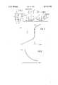
- FIG. 3is a graph of resistance to alternating current (ordinate) of a current-limiting type sensor with respect to temperature T.
- Such sensorsas only schematically shown in FIG. 1, have an ion conductive solid electrolyte body, for example, made of zirconium dioxide on which two electrodes, applied to different surface regions of the zirconium dioxide are applied.
- the electrodesare gas pervious, and have a measuring voltage applied thereto.
- a higher, or lower diffusion limiting currentwill establish itself which, as well known, is limited by the diffusion rate of the oxygen molecules which reach the electrodes.
- Sensors of this typewhen exposed to the exhaust gas from a combustion process, for example, when positioned in the exhaust manifold or exhaust gas system of an internal combustion engine, have an operating characteristic as shown in FIG. 2.
- the current measured through the sensoris shown with respect to voltage (ordinate).
- the currentis steady or constant over a certain measuring voltage region applied to the electrodes.
- the aforementioned Dietz application and patentare referred to.
- current emitting-type sensorsshould operate at between 500° C. and 700° C., and should be heated to that temperature range, in order to hold the exchange current at a higher level than the limiting current determined only by the diffusion.
- the current-limiting sensorprovides output values which are essentially independent of temperature within a range of about 100° C. Temperature and speed of application, or rate of application of the measured gas to the sensor are, however, subject to wide variations. It is, therefore, desirable to maintain the sensor at a temperature independent of that of the gas to be sensed, and to provide for independent temperature control thereof.
- the current limiting-type sensoris an element which responds not only to changes in oxygen level but also to changes in voltage. Thus it responds to two different parameters.
- the dynamic behavior of current-limiting sensors with respect to voltage changesis highly dependent on frequency, that is, the frequency of the voltage applied to the sensor. At low frequencies, the sensor current within the region a of FIG. 2 is essentially independent of changes in frequency. As the frequency increases, however, current changes will result which, at frequencies of about 1 kHz, or more, will become proportional to the changes in applied voltage.
- the resistance to alternating currenthas been found to be less than the dc resistance of the electrode system.
- the resistance to alternating current, R altis highly temperature dependent and, upon increasing temperature, is similar to a decreasing e function, as illustrated in FIG. 3.
- the different behavior of resistance of the solid electrolyte body with respect to applied voltage when the voltage is either steady, or varies at a rate of about 1 kHz or morecan be used to determine the temperature of the sensor and to derive an output signal which, in turn, can be indicated or applied to control heating of the sensor such that a predetermined command or desire temperature is being maintained.
- an ac voltage sourceis applied to the sensor, which is a current-limiting sensor.
- the a-c voltageis additionally or serially connected to the d-c voltage supply (see FIG. 1).
- the a-c voltage proportion of the applied voltageis essentially independent on oxygen concentration.
- the limit currentis independent of voltage within the range a, as seen in FIG. 2.
- the output voltageis essentially unaffected by the superposed ac.
- the dc componentthus is not changed by addition of an ac voltage source, so that the output signal representative of oxygen concentration can be used, as well known and as customary to determine the oxygen concentration of the gas to which the sensor is exposed.
- the alternating currenthowever, the magnitude of which is determined only by the alternating current resistance, R alt , of the sensor can be filtered out and separated from the dc component, or the slowly varying dc component so that the ac flowing can be utilized as a parameter or value representative of temperature and thus employed for indication or control purposes.
- the amplitude of the alternating voltage, in current-limiting sensors,is limited only by the magnitude of the current-limiting range a of FIG. 2. Amplitude values of alternating voltages in the order of about 10% of dc voltage have been found suitable, see FIG. 2, U ⁇ , which shows the superposition or modulating range of the a-c voltage on the applied d-c voltage required for limit current operation of the sensor.
- FIG. 1illustrates a temperature control system.
- a dc source 1 and ac source 2 having terminals 2a, 2bare serially connected.
- the series connection of the dc source and the ac sourceis connected to a resistor 3 which, in turn, is serially connected with a polarographic sensor 4, for example, of the type of the above referenced Dietz patent.
- the sensor 4has a solid electrolyte body 4c and two electrodes 4a, 4b applied thereto.
- dc source 1, ac source 2, resistor 3 and sensor 4form a closed current loop network.
- a comparator, or differential amplifier 5is connected across the resistor 3.
- the differential amplifier 5has its output connected to two channels.
- One channelhas a loss pass filter 6 therein, which is connected to a measuring element 8; rather than using a measuring element, other control systems, or other utilization apparatus can be connected thereto, for example, to control the air/fuel ratio of an internal combustion engine, the exhaust gases of which are to be measured by the sensor 4; or to control the air/fuel supply of a burner or furnace system.
- the second channel connected to the output of the differential amplifier 5is formed by a high pass filter 7, connected to a rectifier 9.
- the output of the rectifier 9is connected to the inverting input of a comparator, which, for example, may be formed by an operational amplifier, a differential amplifier or the like.
- the direct inputreceives a reference value, for example derived from a potentiometer connected to a regulated source of voltage supply and applying a voltage to the comparator 10 representative of a predetermined temperature value of the sensor.
- the comparator 10controls the heating resistor 11, located adjacent the sensor or forming part of an assembly thereof in accordance with any known and suitable structure, to heat the sensor, or sensing region of the sensor 4.
- Suitable amplification apparatus between the comparator 10 and the heater 11, and connecting and buffer amplifiershave been omitted for clarity and can be used in accordance with well known circuit design.
- a voltagewill be dropped across the resistor 3 which has a dc component and ac component superimposed thereon.
- the dc componentis representative of the oxygen concentration of the sensor 4.
- the ac componentwill be determined by the ac resistance R alt of the sensor 4, and is temperature dependent. This voltage is sensed by the differential amplifier 5 and amplified.
- Low pass filter 6suppresses the ac components of the voltage at resistor 3.
- the low pass filter 6is so designed that the frequency of ac voltage 2 cannot pass through the low pass filter 6.
- the instrument 8, thus,will have applied thereto a voltage which is representative of oxygen concentration of the sensor 4, for indication or for application for further control functions.
- the high pass filter 7is so designed that it rejects dc components. Only ac voltage components are passed thereby. To provide for improved signal-to-noise rejection, it is also possible to utilize a band pass filter rather than a high pass filter, and designed to pass the frequency of the high frequency source 2, but to suppress all others.
- the pure ac signal componentis rectified by rectifier 9 which, preferably, is a peak value rectifier.
- the output signal derived from rectifier 9, then,will be temperature dependent. This signal is suitable for temperature indication, or for further control functions.
- the comparator 10receives the output signal from the peak rectifier 9, and compares this output signal with a reference to so control the heating resistor 11 that the temperature of the sensor 4 remains at a constant, and command value. Variations in temperature and rate of application of the sensing gas, which also affect temperature therefore can be compensated, so that the temperature of the sensor will not leave a predetermined operating range. An analog output can be obtained, as explained in the referenced Dietz patent.
Landscapes
- General Physics & Mathematics (AREA)
- Physics & Mathematics (AREA)
- Chemical & Material Sciences (AREA)
- Life Sciences & Earth Sciences (AREA)
- Automation & Control Theory (AREA)
- Chemical Kinetics & Catalysis (AREA)
- Electrochemistry (AREA)
- Engineering & Computer Science (AREA)
- Health & Medical Sciences (AREA)
- Biochemistry (AREA)
- General Health & Medical Sciences (AREA)
- Immunology (AREA)
- Pathology (AREA)
- Analytical Chemistry (AREA)
- Molecular Biology (AREA)
- Measuring Oxygen Concentration In Cells (AREA)
Abstract
Description
Claims (9)
Applications Claiming Priority (2)
| Application Number | Priority Date | Filing Date | Title |
|---|---|---|---|
| DE19813117790DE3117790A1 (en) | 1981-05-06 | 1981-05-06 | METHOD AND DEVICE FOR MEASURING TEMPERATURE WITH OXYGEN PROBES |
| DE3117790 | 1981-05-06 |
Publications (1)
| Publication Number | Publication Date |
|---|---|
| US4419190Atrue US4419190A (en) | 1983-12-06 |
Family
ID=6131524
Family Applications (1)
| Application Number | Title | Priority Date | Filing Date |
|---|---|---|---|
| US06/357,803Expired - LifetimeUS4419190A (en) | 1981-05-06 | 1982-03-12 | Method and apparatus to measure the operating temperature of solid electrolyte-type gas sensors |
Country Status (3)
| Country | Link |
|---|---|
| US (1) | US4419190A (en) |
| JP (1) | JPS57187646A (en) |
| DE (1) | DE3117790A1 (en) |
Cited By (44)
| Publication number | Priority date | Publication date | Assignee | Title |
|---|---|---|---|---|
| US4543176A (en)* | 1983-03-08 | 1985-09-24 | Nippondenxo Co., Ltd. | Oxygen concentration detector under temperature control |
| US4588979A (en)* | 1984-10-05 | 1986-05-13 | Dbx, Inc. | Analog-to-digital converter |
| US4595485A (en)* | 1983-03-14 | 1986-06-17 | Kabushiki Kaisha Toyota Chuo Kenkyusho | Limiting electric current type oxygen sensor |
| US4609452A (en)* | 1984-02-08 | 1986-09-02 | Mitsubishi Denki Kabushiki Kaisha | Engine air/fuel ratio sensing device |
| US4609453A (en)* | 1984-02-08 | 1986-09-02 | Mitsubishi Denki Kabushiki Kaisha | Engine air/fuel ratio sensing device |
| US4626338A (en)* | 1981-05-01 | 1986-12-02 | Kabushiki Kaisha Toyota Chuo Kenkyusho | Equipment for detecting oxygen concentration |
| US4664756A (en)* | 1984-07-07 | 1987-05-12 | Kyoto Electronics Manufacturing Co., Ltd. | Method of detecting electrode potential in Karl Fischer moisture meter |
| US4708777A (en)* | 1984-02-06 | 1987-11-24 | Nippondenso Co., Ltd. | Method and apparatus for controlling heater of a gas sensor |
| US5090387A (en)* | 1989-08-30 | 1992-02-25 | Robert Bosch Gmbh | Method and arrangement for checking the operational capability of an exhaust-gas probe heater and the supply system thereof |
| US5091698A (en)* | 1989-02-04 | 1992-02-25 | Robert Bosch Gmbh | Circuit for measuring the internal resistance of a lambda probe |
| AU623183B2 (en)* | 1988-10-21 | 1992-05-07 | Robert Bosch Gmbh | A process and device for determining temperature with the aid of the internal resistance of a lambda sensor |
| US5130002A (en)* | 1989-11-15 | 1992-07-14 | Ngk Insulators, Ltd. | Method of processing oxygen concentration sensor by applying ac current, and the thus processed sensor |
| AU627232B2 (en)* | 1988-10-22 | 1992-08-20 | Robert Bosch Gmbh | A process and device for determining the internal resistance of lambda probes and for heating regulation using the internal resistance |
| US5173167A (en)* | 1989-11-15 | 1992-12-22 | Ngk Insulators, Ltd. | Oxygen concentration sensor having sensing element with electrodes having minute cracks on surfaces thereof |
| US5218946A (en)* | 1991-09-26 | 1993-06-15 | Robert Bosch Gmbh | Method and arrangement for checking the operability of an electric heater in a motor vehicle |
| US5285762A (en)* | 1989-12-20 | 1994-02-15 | Robert Bosch Gmbh | Method and arrangement for monitoring the operability of a probe heating device |
| US5327780A (en)* | 1991-08-27 | 1994-07-12 | Robert Bosch Gmbh | Method and arrangement for monitoring the operability of a heater of an oxygen measuring probe |
| GB2285314A (en)* | 1993-12-30 | 1995-07-05 | Bosch Gmbh Robert | Device for calibrating and evaluating signals from exhaust gas oxygen probes |
| US5461902A (en)* | 1993-10-12 | 1995-10-31 | Toyota Jidosha Kabushiki Kaisha | Apparatus for thermally controlling an oxygen sensor of internal combustion engine |
| GB2310725A (en)* | 1996-02-28 | 1997-09-03 | Denso Corp | Determining resistance of oxygen sensor |
| US5781878A (en)* | 1995-06-05 | 1998-07-14 | Nippondenso Co., Ltd. | Apparatus and method for diagnosing degradation or malfunction of oxygen sensor |
| US5898107A (en)* | 1996-09-07 | 1999-04-27 | Robert Bosch Gmbh | Method and arrangement for monitoring the operation of a hydrocarbon sensor for an internal combustion engine |
| US6067841A (en)* | 1997-04-25 | 2000-05-30 | Denso Corporation | Method of detecting element resistance of gas concentration sensor |
| US6084418A (en)* | 1996-02-28 | 2000-07-04 | Denso Corporation | Method for accurately detecting sensor element resistance |
| US6099717A (en)* | 1996-11-06 | 2000-08-08 | Ngk Spark Plug Co., Ltd. | Method of and apparatus for detecting a deteriorated condition of a wide range air-fuel ratio sensor |
| US6120677A (en)* | 1996-07-31 | 2000-09-19 | Ngk Spark Plug Co., Ltd. | Temperature control for all range oxygen sensor |
| US6254765B1 (en)* | 1998-08-25 | 2001-07-03 | Robert Bosch Gmbh | Method of regulating the temperature of a sensor |
| DE10027900A1 (en)* | 2000-06-06 | 2001-12-13 | Delphi Tech Inc | Arrangement for determining the operating temperature of exhaust gas probe in IC engine comprises evaluation unit connected to the probe, and switching arrangement arranged between the probe and the evaluation unit |
| WO2001096848A1 (en)* | 2000-06-16 | 2001-12-20 | Siemens Aktiengesellschaft | Device for measuring the internal resistance of a linear lambda probe |
| US6347544B1 (en) | 1997-04-23 | 2002-02-19 | Denso Corporation | Control method for gas concentration sensor |
| US20020189942A1 (en)* | 2001-06-15 | 2002-12-19 | Mitsunobu Niwa | Gas concentration measuring device |
| US6580280B2 (en)* | 2000-12-08 | 2003-06-17 | Denso Corporation | Multilayered gas sensor and a related gas concentration detecting system |
| US20030127325A1 (en)* | 2002-01-09 | 2003-07-10 | Mark Khesin | Method and apparatus for monitoring gases in a combustion system |
| US20030151416A1 (en)* | 2000-07-13 | 2003-08-14 | Stephan Bolz | Circuit for determining the internal resistance of a linear lambda probe |
| WO2003069304A3 (en)* | 2002-02-10 | 2003-12-24 | Agamatrix Inc | Method and apparatus for assay of electrochemical properties |
| US20050252788A1 (en)* | 2004-05-13 | 2005-11-17 | Boris Farber | Method for improving performance and longevity of solid electrolyte gas sensor |
| US20060049048A1 (en)* | 2002-12-27 | 2006-03-09 | Tomonori Kondo | Gas sensor |
| US20080067080A1 (en)* | 2006-08-22 | 2008-03-20 | The Regents Of The University Of California | Multiple frequency method for operating electrochemical sensors |
| US20080094079A1 (en)* | 2006-10-20 | 2008-04-24 | Denso Corporation | Gas concentration detection apparatus having function for detecting sensor element activation status |
| US20080197022A1 (en)* | 2007-02-20 | 2008-08-21 | Denso Corporation | Gas sensor control apparatus designed to ensure accuracy of measurement in gas sensor |
| US20090116534A1 (en)* | 2006-03-16 | 2009-05-07 | Robert Bosch Gmbh | Method for operating a gas sensor |
| US20120086502A1 (en)* | 2008-03-27 | 2012-04-12 | Sensor Electronics Corporation | Device and method for monitoring an electrochemical gas sensor |
| DE102015201849A1 (en) | 2014-02-05 | 2015-08-06 | Denso Corporation | Air-fuel ratio detecting device |
| US11953467B2 (en) | 2020-08-18 | 2024-04-09 | Denso Corporation | Gas concentration detection device |
Families Citing this family (19)
| Publication number | Priority date | Publication date | Assignee | Title |
|---|---|---|---|---|
| JPS57192852A (en)* | 1981-05-25 | 1982-11-27 | Toyota Central Res & Dev Lab Inc | Limiting current type oxygen concentration detector controlled in temperature |
| CA1164946A (en)* | 1981-06-15 | 1984-04-03 | Alex D. Colvin | Method of precisely controlling the temperature of an oxygen sensor |
| DE3126238A1 (en)* | 1981-07-03 | 1983-01-20 | Robert Bosch Gmbh, 7000 Stuttgart | DEVICE FOR OPERATING AN OXYGEN PROBE IN A LARGE TEMPERATURE RANGE |
| DE3342339A1 (en)* | 1983-11-23 | 1985-05-30 | Siemens AG, 1000 Berlin und 8000 München | CONTROL DEVICE FOR A HEATING BURNER |
| JPS61122556A (en)* | 1984-11-19 | 1986-06-10 | Nippon Denso Co Ltd | Electric energy controller of heater for oxygen concentration sensor |
| DE3817518A1 (en)* | 1988-05-24 | 1989-12-07 | Pierburg Gmbh | METHOD AND DEVICE FOR DETERMINING THE READY FOR OPERATION OF A LAMBDA MEASURING PROBE |
| DE4034185A1 (en)* | 1990-10-26 | 1992-04-30 | Lambrecht Wilhelm Gmbh | DEVICE FOR MEASURING THE STEAM PARTIAL PRESSURE |
| DE4106308C2 (en)* | 1991-02-28 | 2000-06-15 | Bosch Gmbh Robert | Method and device for temperature control for an exhaust gas probe |
| US5245979A (en)* | 1992-10-28 | 1993-09-21 | Ford Motor Company | Oxygen sensor system with a dynamic heater malfunction detector |
| US5228426A (en)* | 1992-10-28 | 1993-07-20 | Ford Motor Company | Oxygen sensor system with an automatic heater malfunction detector |
| JPH0718837B2 (en)* | 1993-02-22 | 1995-03-06 | 株式会社日立製作所 | Air-fuel ratio detector |
| FR2771815B1 (en)* | 1997-12-02 | 2000-02-18 | Renault | METHOD FOR ESTIMATING THE TEMPERATURE OF EXHAUST GASES FROM AN ENGINE |
| JP4385423B2 (en)* | 1999-02-04 | 2009-12-16 | トヨタ自動車株式会社 | Exhaust temperature measuring device |
| DE10029831C1 (en)* | 2000-06-16 | 2002-02-28 | Siemens Ag | Method and device for operating a linear lambda probe |
| DE10034060A1 (en)* | 2000-07-13 | 2002-02-28 | Siemens Ag | Internal resistance measurement circuit for linear lambda sensor, employs principle of synchronous demodulation |
| DE10101755C1 (en) | 2001-01-16 | 2002-07-11 | Siemens Ag | Device for determining the internal resistance of a linear oxygen probe |
| DE102009050324B4 (en)* | 2009-10-22 | 2022-06-02 | Vitesco Technologies GmbH | Method for operating an exhaust gas sensor |
| DE102009053127A1 (en)* | 2009-11-13 | 2011-05-19 | Staxera Gmbh | Method for measuring e.g. content of oxygen in exhaust gas of fuel cell arrangement in motor vehicle, involves operating gas sensor in measurement mode for determining temperature in electrolysis operation |
| DE102010031315A1 (en)* | 2010-07-14 | 2012-01-19 | Bayerische Motoren Werke Aktiengesellschaft | Method for computer-based determination of temperature of lambda sensors i.e. broadband lambda sensors, involves computing inner resistance, and determining temperature of lambda sensor from known context of inner resistance |
Citations (3)
| Publication number | Priority date | Publication date | Assignee | Title |
|---|---|---|---|---|
| DE2744844A1 (en)* | 1976-10-08 | 1978-04-13 | Nissan Motor | METHOD AND DEVICE FOR CONTROLLING THE AIR-FUEL MIXTURE OF A COMBUSTION ENGINE |
| DE2711880A1 (en)* | 1977-03-18 | 1978-09-21 | Bosch Gmbh Robert | PROBE FOR MEASURING THE OXYGEN CONCENTRATION |
| US4376026A (en)* | 1980-08-01 | 1983-03-08 | The North American Manufacturing Company | Oxygen concentration measurement and control |
Family Cites Families (1)
| Publication number | Priority date | Publication date | Assignee | Title |
|---|---|---|---|---|
| DE2913279C2 (en)* | 1979-04-03 | 1983-03-17 | Licentia Patent-Verwaltungs-Gmbh, 6000 Frankfurt | Electrical resistance temperature sensor |
- 1981
- 1981-05-06DEDE19813117790patent/DE3117790A1/enactiveGranted
- 1982
- 1982-03-12USUS06/357,803patent/US4419190A/ennot_activeExpired - Lifetime
- 1982-05-04JPJP57073499Apatent/JPS57187646A/enactiveGranted
Patent Citations (4)
| Publication number | Priority date | Publication date | Assignee | Title |
|---|---|---|---|---|
| DE2744844A1 (en)* | 1976-10-08 | 1978-04-13 | Nissan Motor | METHOD AND DEVICE FOR CONTROLLING THE AIR-FUEL MIXTURE OF A COMBUSTION ENGINE |
| DE2711880A1 (en)* | 1977-03-18 | 1978-09-21 | Bosch Gmbh Robert | PROBE FOR MEASURING THE OXYGEN CONCENTRATION |
| US4356065A (en)* | 1977-03-18 | 1982-10-26 | Robert Bosch Gmbh | Polarographic oxygen concentration sensor and method of determining oxygen content in the exhaust gases of an internal combustion engine |
| US4376026A (en)* | 1980-08-01 | 1983-03-08 | The North American Manufacturing Company | Oxygen concentration measurement and control |
Cited By (72)
| Publication number | Priority date | Publication date | Assignee | Title |
|---|---|---|---|---|
| US4626338A (en)* | 1981-05-01 | 1986-12-02 | Kabushiki Kaisha Toyota Chuo Kenkyusho | Equipment for detecting oxygen concentration |
| US4543176A (en)* | 1983-03-08 | 1985-09-24 | Nippondenxo Co., Ltd. | Oxygen concentration detector under temperature control |
| US4595485A (en)* | 1983-03-14 | 1986-06-17 | Kabushiki Kaisha Toyota Chuo Kenkyusho | Limiting electric current type oxygen sensor |
| US4708777A (en)* | 1984-02-06 | 1987-11-24 | Nippondenso Co., Ltd. | Method and apparatus for controlling heater of a gas sensor |
| US4609452A (en)* | 1984-02-08 | 1986-09-02 | Mitsubishi Denki Kabushiki Kaisha | Engine air/fuel ratio sensing device |
| US4609453A (en)* | 1984-02-08 | 1986-09-02 | Mitsubishi Denki Kabushiki Kaisha | Engine air/fuel ratio sensing device |
| US4664756A (en)* | 1984-07-07 | 1987-05-12 | Kyoto Electronics Manufacturing Co., Ltd. | Method of detecting electrode potential in Karl Fischer moisture meter |
| US4588979A (en)* | 1984-10-05 | 1986-05-13 | Dbx, Inc. | Analog-to-digital converter |
| US5129258A (en)* | 1988-10-21 | 1992-07-14 | Robert Bosch Gmbh | Method for determining temperature with the aid of the internal resistance of a lambda sensor |
| AU623183B2 (en)* | 1988-10-21 | 1992-05-07 | Robert Bosch Gmbh | A process and device for determining temperature with the aid of the internal resistance of a lambda sensor |
| AU627232B2 (en)* | 1988-10-22 | 1992-08-20 | Robert Bosch Gmbh | A process and device for determining the internal resistance of lambda probes and for heating regulation using the internal resistance |
| US5291417A (en)* | 1988-10-22 | 1994-03-01 | Robert Bosch Gmbh | Method and arrangement for determining the internal resistance of a lambda probe and for the closed-loop heating control with the aid of the internal resistance |
| US5091698A (en)* | 1989-02-04 | 1992-02-25 | Robert Bosch Gmbh | Circuit for measuring the internal resistance of a lambda probe |
| US5090387A (en)* | 1989-08-30 | 1992-02-25 | Robert Bosch Gmbh | Method and arrangement for checking the operational capability of an exhaust-gas probe heater and the supply system thereof |
| US5130002A (en)* | 1989-11-15 | 1992-07-14 | Ngk Insulators, Ltd. | Method of processing oxygen concentration sensor by applying ac current, and the thus processed sensor |
| US5173167A (en)* | 1989-11-15 | 1992-12-22 | Ngk Insulators, Ltd. | Oxygen concentration sensor having sensing element with electrodes having minute cracks on surfaces thereof |
| US5285762A (en)* | 1989-12-20 | 1994-02-15 | Robert Bosch Gmbh | Method and arrangement for monitoring the operability of a probe heating device |
| US5327780A (en)* | 1991-08-27 | 1994-07-12 | Robert Bosch Gmbh | Method and arrangement for monitoring the operability of a heater of an oxygen measuring probe |
| US5218946A (en)* | 1991-09-26 | 1993-06-15 | Robert Bosch Gmbh | Method and arrangement for checking the operability of an electric heater in a motor vehicle |
| US5461902A (en)* | 1993-10-12 | 1995-10-31 | Toyota Jidosha Kabushiki Kaisha | Apparatus for thermally controlling an oxygen sensor of internal combustion engine |
| US5524472A (en)* | 1993-12-30 | 1996-06-11 | Robert Bosch Gmbh | Evaluating arrangement for the signal of an oxygen probe |
| GB2285314B (en)* | 1993-12-30 | 1997-11-26 | Bosch Gmbh Robert | Evaluation devices for signals of oxygen probes |
| GB2285314A (en)* | 1993-12-30 | 1995-07-05 | Bosch Gmbh Robert | Device for calibrating and evaluating signals from exhaust gas oxygen probes |
| US5781878A (en)* | 1995-06-05 | 1998-07-14 | Nippondenso Co., Ltd. | Apparatus and method for diagnosing degradation or malfunction of oxygen sensor |
| GB2310725A (en)* | 1996-02-28 | 1997-09-03 | Denso Corp | Determining resistance of oxygen sensor |
| DE19708011B4 (en)* | 1996-02-28 | 2009-12-03 | DENSO CORPORATION, Kariya-shi | Method for detecting sensor element resistances |
| GB2310725B (en)* | 1996-02-28 | 1999-08-25 | Denso Corp | Method for detecting sensor element resistance |
| US6084418A (en)* | 1996-02-28 | 2000-07-04 | Denso Corporation | Method for accurately detecting sensor element resistance |
| US6120677A (en)* | 1996-07-31 | 2000-09-19 | Ngk Spark Plug Co., Ltd. | Temperature control for all range oxygen sensor |
| US5898107A (en)* | 1996-09-07 | 1999-04-27 | Robert Bosch Gmbh | Method and arrangement for monitoring the operation of a hydrocarbon sensor for an internal combustion engine |
| US6099717A (en)* | 1996-11-06 | 2000-08-08 | Ngk Spark Plug Co., Ltd. | Method of and apparatus for detecting a deteriorated condition of a wide range air-fuel ratio sensor |
| US6868712B2 (en) | 1997-04-23 | 2005-03-22 | Denso Corporation | Control method for gas concentration sensor |
| US6347544B1 (en) | 1997-04-23 | 2002-02-19 | Denso Corporation | Control method for gas concentration sensor |
| US20020056310A1 (en)* | 1997-04-23 | 2002-05-16 | Denso Corporation | Control method for gas concentration sensor |
| US6067841A (en)* | 1997-04-25 | 2000-05-30 | Denso Corporation | Method of detecting element resistance of gas concentration sensor |
| US6254765B1 (en)* | 1998-08-25 | 2001-07-03 | Robert Bosch Gmbh | Method of regulating the temperature of a sensor |
| DE10027900A1 (en)* | 2000-06-06 | 2001-12-13 | Delphi Tech Inc | Arrangement for determining the operating temperature of exhaust gas probe in IC engine comprises evaluation unit connected to the probe, and switching arrangement arranged between the probe and the evaluation unit |
| DE10027900B4 (en)* | 2000-06-06 | 2018-11-15 | Delphi Technologies, Inc. | Arrangement for determining the operating temperature of an exhaust gas probe |
| WO2001096848A1 (en)* | 2000-06-16 | 2001-12-20 | Siemens Aktiengesellschaft | Device for measuring the internal resistance of a linear lambda probe |
| US20030127323A1 (en)* | 2000-06-16 | 2003-07-10 | Stephan Bolz | Device for measuring the internal resistance of a linear lambda probe |
| US6861850B2 (en) | 2000-06-16 | 2005-03-01 | Siemens Aktiengesellschaft | Device for measuring the internal resistance of a linear lambda probe |
| US20030151416A1 (en)* | 2000-07-13 | 2003-08-14 | Stephan Bolz | Circuit for determining the internal resistance of a linear lambda probe |
| US6867605B2 (en)* | 2000-07-13 | 2005-03-15 | Siemens Aktiengesellschaft | Circuit for determining the internal resistance of a linear lambda probe |
| US6580280B2 (en)* | 2000-12-08 | 2003-06-17 | Denso Corporation | Multilayered gas sensor and a related gas concentration detecting system |
| US20020189942A1 (en)* | 2001-06-15 | 2002-12-19 | Mitsunobu Niwa | Gas concentration measuring device |
| US7128818B2 (en)* | 2002-01-09 | 2006-10-31 | General Electric Company | Method and apparatus for monitoring gases in a combustion system |
| US20030127325A1 (en)* | 2002-01-09 | 2003-07-10 | Mark Khesin | Method and apparatus for monitoring gases in a combustion system |
| US10413228B2 (en) | 2002-02-10 | 2019-09-17 | Agamatrix, Inc. | Method and apparatus for assay of electrochemical properties |
| US9188525B2 (en) | 2002-02-10 | 2015-11-17 | Agamatrix, Inc. | Method and apparatus for assay of electrochemical properties |
| US9572524B2 (en) | 2002-02-10 | 2017-02-21 | Agamatrix, Inc. | Method and apparatus for assay of electrochemical properties |
| US8293094B2 (en) | 2002-02-10 | 2012-10-23 | Agamatrix, Inc. | Method and apparatus for assay of electrochemical properties |
| WO2003069304A3 (en)* | 2002-02-10 | 2003-12-24 | Agamatrix Inc | Method and apparatus for assay of electrochemical properties |
| AU2003210957B2 (en)* | 2002-02-10 | 2009-09-10 | Agamatrix, Inc. | Method and apparatus for assay of electrochemical properties |
| US7601249B2 (en) | 2002-02-10 | 2009-10-13 | Agamatrix, Inc. | Method and apparatus for assay of electrochemical properties |
| US20050069892A1 (en)* | 2002-02-10 | 2005-03-31 | Iyengar Sridhar G. | Method and apparatus for assay of electrochemical properties |
| US20100078335A1 (en)* | 2002-02-10 | 2010-04-01 | Agamatrix, Inc. | Method and apparatus for assay of electrochemical properties |
| US20060049048A1 (en)* | 2002-12-27 | 2006-03-09 | Tomonori Kondo | Gas sensor |
| US20050252788A1 (en)* | 2004-05-13 | 2005-11-17 | Boris Farber | Method for improving performance and longevity of solid electrolyte gas sensor |
| US20090116534A1 (en)* | 2006-03-16 | 2009-05-07 | Robert Bosch Gmbh | Method for operating a gas sensor |
| US8201993B2 (en)* | 2006-03-16 | 2012-06-19 | Robert Bosch Gmbh | Method for operating a gas sensor |
| US8177957B2 (en)* | 2006-08-22 | 2012-05-15 | Lawrence Livermore National Security, Llc | Multiple frequency method for operating electrochemical sensors |
| US20080067080A1 (en)* | 2006-08-22 | 2008-03-20 | The Regents Of The University Of California | Multiple frequency method for operating electrochemical sensors |
| CN101165480B (en)* | 2006-10-20 | 2011-04-20 | 株式会社电装 | Gas concentration detection apparatus having function for detecting sensor element activation status |
| US7671600B2 (en) | 2006-10-20 | 2010-03-02 | Denso Corporation | Gas concentration detection apparatus having function for detecting sensor element activation status |
| US20080094079A1 (en)* | 2006-10-20 | 2008-04-24 | Denso Corporation | Gas concentration detection apparatus having function for detecting sensor element activation status |
| US20080197022A1 (en)* | 2007-02-20 | 2008-08-21 | Denso Corporation | Gas sensor control apparatus designed to ensure accuracy of measurement in gas sensor |
| US8052863B2 (en) | 2007-02-20 | 2011-11-08 | Denso Corporation | Gas sensor control apparatus designed to ensure accuracy of measurement in gas sensor |
| US9057690B2 (en)* | 2008-03-27 | 2015-06-16 | Sensor Electronics Corporation | Device for monitoring an electrochemical gas sensor |
| US20120086502A1 (en)* | 2008-03-27 | 2012-04-12 | Sensor Electronics Corporation | Device and method for monitoring an electrochemical gas sensor |
| DE102015201849A1 (en) | 2014-02-05 | 2015-08-06 | Denso Corporation | Air-fuel ratio detecting device |
| US9523654B2 (en) | 2014-02-05 | 2016-12-20 | Denso Corporation | Air-fuel ratio detection device |
| US11953467B2 (en) | 2020-08-18 | 2024-04-09 | Denso Corporation | Gas concentration detection device |
Also Published As
| Publication number | Publication date |
|---|---|
| DE3117790C2 (en) | 1990-06-28 |
| JPH0424657B2 (en) | 1992-04-27 |
| JPS57187646A (en) | 1982-11-18 |
| DE3117790A1 (en) | 1982-11-25 |
Similar Documents
| Publication | Publication Date | Title |
|---|---|---|
| US4419190A (en) | Method and apparatus to measure the operating temperature of solid electrolyte-type gas sensors | |
| EP0068321B1 (en) | Oxygen sensing device having solid electrolyte cell and means for supplying controlled current thereto | |
| US4543176A (en) | Oxygen concentration detector under temperature control | |
| EP0035177B1 (en) | Method and appparatus for sensing oxygen in a gas atmosphere | |
| US4804454A (en) | Oxygen concentration sensing apparatus | |
| US4440621A (en) | System for detection of air/fuel ratio in IC engine by using oxygen sensor operated with supply of current | |
| US4601273A (en) | Air/fuel ratio monitoring system in IC engine using oxygen sensor | |
| US4594139A (en) | Air/fuel ratio detector | |
| EP0068323A2 (en) | System for feedback control of air/fuel ratio in IC engine with means to control current supply to oxygen sensor | |
| GB1470721A (en) | Air fuel ratio sensor | |
| CA1098192A (en) | Compensation for inherent fluctuation in output level of exhaust sensor in air-fuel ratio control system for internal combustion engine | |
| US4818977A (en) | Combustible gas detector having temperature stabilization capability | |
| US4376026A (en) | Oxygen concentration measurement and control | |
| EP0026116B1 (en) | Oxygen sensing apparatus of the resistive type | |
| US3674436A (en) | Exhaust gas analyzer for internal combustion engines | |
| CA1185324A (en) | Air/fuel ratio monitoring system in ic engine using oxygen sensor | |
| GB2184847A (en) | Method of controlling an oxygen concentration sensor | |
| EP0103212B1 (en) | Thermal flow meter | |
| US4748953A (en) | Air/fuel ratio control apparatus for internal combustion engines | |
| US4762604A (en) | Oxygen concentration sensing apparatus | |
| US4759827A (en) | Oxygen concentration detection apparatus with an adjusting device and its adjusting method | |
| CN1108522C (en) | Device for finding concentration of component in gas mixture | |
| EP0089630A2 (en) | Device for measuring oxygen concentration in exhaust gas | |
| JPS59208451A (en) | Air-fuel ratio sensor for engine | |
| EP0311353A2 (en) | An air-fuel ratio sensor for an internal combustion engine |
Legal Events
| Date | Code | Title | Description |
|---|---|---|---|
| AS | Assignment | Owner name:ROBERT BOSCH GMBH; POSTFACH 50 D-7000 STUTTGART 1 Free format text:ASSIGNMENT OF ASSIGNORS INTEREST.;ASSIGNORS:DIETZ, HERMANN;GROB, FERDINAND;MULLER, KLAUS;AND OTHERS;REEL/FRAME:003989/0426;SIGNING DATES FROM 19820225 TO 19820301 | |
| STCF | Information on status: patent grant | Free format text:PATENTED CASE | |
| FEPP | Fee payment procedure | Free format text:PAYOR NUMBER ASSIGNED (ORIGINAL EVENT CODE: ASPN); ENTITY STATUS OF PATENT OWNER: LARGE ENTITY | |
| MAFP | Maintenance fee payment | Free format text:PAYMENT OF MAINTENANCE FEE, 4TH YEAR, PL 96-517 (ORIGINAL EVENT CODE: M170); ENTITY STATUS OF PATENT OWNER: LARGE ENTITY Year of fee payment:4 | |
| FEPP | Fee payment procedure | Free format text:MAINTENANCE FEE REMINDER MAILED (ORIGINAL EVENT CODE: REM.); ENTITY STATUS OF PATENT OWNER: LARGE ENTITY | |
| FEPP | Fee payment procedure | Free format text:SURCHARGE FOR LATE PAYMENT, PL 96-517 (ORIGINAL EVENT CODE: M176); ENTITY STATUS OF PATENT OWNER: LARGE ENTITY | |
| MAFP | Maintenance fee payment | Free format text:PAYMENT OF MAINTENANCE FEE, 8TH YEAR, PL 96-517 (ORIGINAL EVENT CODE: M171); ENTITY STATUS OF PATENT OWNER: LARGE ENTITY Year of fee payment:8 | |
| MAFP | Maintenance fee payment | Free format text:PAYMENT OF MAINTENANCE FEE, 12TH YEAR, LARGE ENTITY (ORIGINAL EVENT CODE: M185); ENTITY STATUS OF PATENT OWNER: LARGE ENTITY Year of fee payment:12 | |
| FEPP | Fee payment procedure | Free format text:PAYOR NUMBER ASSIGNED (ORIGINAL EVENT CODE: ASPN); ENTITY STATUS OF PATENT OWNER: LARGE ENTITY Free format text:PAYER NUMBER DE-ASSIGNED (ORIGINAL EVENT CODE: RMPN); ENTITY STATUS OF PATENT OWNER: LARGE ENTITY |