US4419093A - Method of receiving and disposing of fluids from the body - Google Patents
Method of receiving and disposing of fluids from the bodyDownload PDFInfo
- Publication number
- US4419093A US4419093AUS06/301,525US30152581AUS4419093AUS 4419093 AUS4419093 AUS 4419093AUS 30152581 AUS30152581 AUS 30152581AUS 4419093 AUS4419093 AUS 4419093A
- Authority
- US
- United States
- Prior art keywords
- container
- cover
- canister
- rigid
- lid
- Prior art date
- Legal status (The legal status is an assumption and is not a legal conclusion. Google has not performed a legal analysis and makes no representation as to the accuracy of the status listed.)
- Expired - Lifetime
Links
Images

Classifications
- A—HUMAN NECESSITIES
- A61—MEDICAL OR VETERINARY SCIENCE; HYGIENE
- A61M—DEVICES FOR INTRODUCING MEDIA INTO, OR ONTO, THE BODY; DEVICES FOR TRANSDUCING BODY MEDIA OR FOR TAKING MEDIA FROM THE BODY; DEVICES FOR PRODUCING OR ENDING SLEEP OR STUPOR
- A61M1/00—Suction or pumping devices for medical purposes; Devices for carrying-off, for treatment of, or for carrying-over, body-liquids; Drainage systems
- A61M1/60—Containers for suction drainage, adapted to be used with an external suction source
- A61M1/604—Bag or liner in a rigid container, with suction applied to both
- A—HUMAN NECESSITIES
- A61—MEDICAL OR VETERINARY SCIENCE; HYGIENE
- A61M—DEVICES FOR INTRODUCING MEDIA INTO, OR ONTO, THE BODY; DEVICES FOR TRANSDUCING BODY MEDIA OR FOR TAKING MEDIA FROM THE BODY; DEVICES FOR PRODUCING OR ENDING SLEEP OR STUPOR
- A61M1/00—Suction or pumping devices for medical purposes; Devices for carrying-off, for treatment of, or for carrying-over, body-liquids; Drainage systems
- A61M1/71—Suction drainage systems
- A61M1/78—Means for preventing overflow or contamination of the pumping systems
- A61M1/784—Means for preventing overflow or contamination of the pumping systems by filtering, sterilising or disinfecting the exhaust air, e.g. swellable filter valves
Definitions
- the present inventionrelates to medical suction apparatus, and more particularly relates to a disposable suction collection liner and mounting assembly therefor.
- suction apparatushas long been used in hospitals to remove fluids from patients during various medical procedures.
- Such suction apparatushas included glass and plastic containers or receptacles for receiving fluids.
- linersare thin-walled pliable plastic members which do not have enough rigidity to maintain their shape.
- the canisterseach include a cover with a patient port for receiving fluid from a patient and a vacuum port for establishing a vacuum within the liner. The vacuum draws fluid through the patient port for collection in the liner. The vacuum port also applies countervailing vacuum to the space between the outer canister and inner flexible liner in order to cause the liner to expand to an open configuration.
- Prior receptacles with disposable flexible linershave suffered one or more disadvantages.
- the linerWhen the liner is filled with fluid and removed from the rigid outer canister, the liner is hard to handle and store because of its flexibility.
- the linersince the liner is in the form of a pliable bag filled with liquid, special disposal handling is required in order to prevent puncturing or bursting due to contact with sharp objects.
- the flexible linersalso can provide erroneous liquid level readings if not fully opened during filling or while being handled.
- the present inventionrelates to improvements thereover, particularly in the liner and in a simple and efficient mounting assembly for the cover, liner and canister which provides significantly enhanced sealing characteristics.
- the present inventionprovides improved medical suction apparatus for receiving fluids from the body of a patient.
- the inventionincludes in combination a rigid outer canister, a disposable semi-rigid inner liner or container, and a cover.
- a mounting assemblycoacts with the canister and cover to seal the container within the canister.
- the containeris a cup-like member which retains its cup-like shape before, during and after use within the canister. Post-use shape retention simplifies disposal handling.
- the canisterhas an open mouth defined by a rim
- the containerhas an open mouth defined by a lip.
- the container lipis supported from the canister rim preferably by an annular sealing support lid on the container lip.
- the lid and containerare preferably a one-piece unit.
- the lidhas an attachment portion snap-fitted to the canister rim.
- the lidhas a sealing portion extending laterally inwardly along the canister rim.
- the lidhas a securement portion which receives the cover in snap-fit relation. Snap-fit mounting of the cover to the lid compresses the container lip between the cover and the sealing portion of the lid.
- the sealing portion of the lidextends inwardly beyond the inner edge of the canister rim and then downwardly a short distance forming a wall portion between the upper sidewalls of the container and canister. This wall portion of the lid establishes the space or gap between the container and canister.
- the covermay be snap-fit mounted to the lid before or after snap-fit mounting of the lid to the canister. After use, the attachment portion of the lid may be released from the canister rim without breaking the seal between the cover and container lip. The cover, lid and container may then be disposed of as a sealed sanitary unit, to avoid contamination.
- a container sealis formed in a second plane in addition to the plane of sealing of the container lip.
- the coverhas a downwardly depending annular flange which engages the interior of the upper sidewall of the container to pinch such sidewall against the wall portion of the lid. This sidewall seal is continuous with the lip seal.
- the wall portion of the lidis pinched between the upper sidewalls of the container and canister, and this compression provides additional sealing.
- the flange portion of the cover and the wall portion of the lidfurther provide additional structural integrity of the above noted disposal unit.
- the interface of the sealing portion of the lid and the container liphas at least one transition step between different vertical thicknesses of each.
- the canister rimhas a top pressure surface which engages the underside of the sealing portion of the lid beneath the transition step to provide an annularly localized sealing pressure line.
- the coverhas an outer edge extending laterally beyond the container lip.
- the securement portion of the lidengages the outer edge of the cover and biases this edge downwardly. This engagement point is offset outwardly of the outer edge of the container lip.
- the container liphas an inner annular thin portion and an outer annular thick portion.
- the lidhas an inner raised shoulder complementing the thickness transition of the container lip.
- An effective lever armis formed through the cover from an area adjacent the thin portion of the container lip to the outer edge of the cover. This provides a continuous resilient biasing force which maintains sealing compression of the container lip.
- the coverhas a downwardly extending annular lug adjacent its outer edge.
- the securement portion of the lidpreferably comprises a plurality of peripherally spaced upstanding locking tabs engaging the top edge of the cover in snap-in relation.
- the vertical dimension of the downwardly extending annular lug on the underside of the coverprovides structural integrity around the periphery of the cover to enhance uniformity of downward lever arm bending force applied by the peripherally spaced locking tabs. This provides substantial annular uniformity in compression of the container lip.
- the bottom of the annular lug on the coveris spaced a small gap above the lid portion therebelow to enable snap-fit mounting of the cover edge past the locking tabs. This also enables slight downward deflection of the outer edge of the cover to maintain resilient seal compression.
- the sealing portion of the lidhas an upstanding annular lug incentric to the lug on the cover and concentric to the outer thick portion of the container lip.
- This lug on the lidhas a small gap between the top thereof and the underside of the cover, so as not to interfere with compression of the container lip by the cover.
- the lug on the lidinterfits in registered relation with the lug on the cover underside.
- a space saving systemwhich significantly enhances efficient use of hospital storage space.
- a plurality of outer canistersare stackable with a minimum of vertical dead space therebetween.
- the containersare likewise stackable.
- the lids on the containersdo not interfere with stacking.
- the receptaclemay be assembled quickly at time of use by simple push down snap-in mounting. The coaction of the container, cover and canister is accurate and reliable.
- an improved methodfor receiving and storing fluids from the body of a patient.
- a disposable semi-rigid containeris placed inside a rigid outer canister having an open mouth defined by a rim.
- a containeris supported from the canister rim such that a space is formed between the wall surfaces of the container and canister.
- a coveris placed over the open mouth of the canister. The cover is retained in place by coacting with the container. Vacuum is applied to the interior of the container, and fluid is drawn from the patient into the container.
- the containeris provided with a lid supporting the container within the canister, and a covering step is provided wherein the container and canister are covered by the cover coacting with the lid.
- the containerhas a lip extending from a sidewall, and the covering step includes resiliently compressing both the sidewall and lip of the container.
- the inventionfurther provides a removal method wherein the cover and container are removed from the canister with the coaction between the cover and container remaining effective.
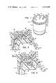
- FIG. 1is an isometric view, partially cut away, of an assembled receptacle constructed in accordance with the invention.
- FIG. 2is an exploded sectional view of the receptacle of FIG. 1.
- FIG. 3is a sectional view of the mounting details for the container liner showing coaction of the sealing support lid with the cover and canister.
- FIG. 4shows an alternate mounting arrangement to that of FIG. 3.
- FIG. 1illustrates a receptacle 10 for receiving fluids from the body of a patient.
- the receptacleincludes a rigid outer canister 12 which supports a disposable semi-rigid liner or container 14 therein.
- a cover 16is snap-fitted over the receptacle 10 and includes a vacuum port 18 for connection to a vacuum source through a tube 19.
- the canister 12has a vacuum port 20 for parallel connection to the vacuum source through a tube 21.
- Vacuum port 18establishes a vacuum within the container 14 and vacuum port 20 establishes a slight vacuum in the space between the container 14 and canister 12 in order to prevent an excessive pressure differential across the container 14.
- the cover 16has a patient port 22 for receiving fluids from the body of a patient through a tube 23.
- the patient fluidsare drawn through patient port 22 by the vacuum within the container 14 and the fluid is collected within the container 14.
- a pouring spout 24is provided in the cover 16 and closed by a removable cap 26 for emptying the fluid within the container when the container and cover are not disposed of as a sealed sanitary unit. Gradations, not shown, may be be provided on the side of container 14 to enable accurate determination of fluid volume therein.
- an automatic shut-off valve 28is provided for closing the vacuum port 18 when fluid within the container reaches a predetermined level.
- Valve 28may comprise any one of a number of shut-off valve designs, as for example the valve disclosed and claimed in the co-pending patent application entitled “Low Profile Shut-Off Valve For Medical Suction Apparatus", Ser. No. 117,058 filed Jan. 31, 1980, now U.S. Pat. No. 4,321,923.
- cover 16, container 14 and canister 12are preferably mounted and sealed in coaction by an annular sealing support lid 30 attached about the top edge of container 14.
- the canister 12has an open mouth defined by an upper annular lateral rim 34 to which sealing lid 30 is snap-fitted.
- Sealing lid 30has a plurality of spaced upstanding locking tabs 38. The cover is pushed down past these locking tabs in snap-fit relation to mount the cover 16 to lid 30.
- Cover 16may be snap-fitted to lid 30 before or after snap-fitting of lid 30 to canister 12.
- container 14 and lid 30are formed as a one-piece unit.
- the upper annular liner lip 76is sealingly compressed between cover 16 and lid 30 to form a vacuum tight seal.
- Container 14 and lid 16may be removed as a unit from canister 12 by snap-fit release of lid 30 from rim 34. This removal does not break the seal between lip 76 and cover 16. This avoids contamination by allowing disposal of the entire sealed container.
- the disposable container 14is a semi-rigid plastic cup-like member formed by injection molding of an inexpensive transparent plastic such as high impact styrene and has a preferred thickness of approximately 0.025 to 0.030 inch.
- the container 14has sufficient rigidity to retain its desired cup-like shape in a pre-use condition at atmospheric pressure without vacuum applied thereto, but yet is thin enough to be quite economically manufactured and light enough to be easily shipped. This is particularly advantageous for ease of handling and for efficient space saving stacking on a hospital shelf prior to use.
- the liddoes not interfere with stacking of a plurality of containers within one another.
- the sidewalls of the containerare tapered inwardly as they extend down to form a frustroconical shape and further enhance pre-use stacking characteristics thereof.
- the bottom of the containerhas a concave cavity 46 formed upwardly therefrom to provide an annular well 48 of reduced lateral dimension for accurate volume readings of small fluid amounts.
- Container 14also maintains its frustroconical cup-like shape in a post-use condition with fluid therein. This is important for disposal handling because of the structural integrity provided thereby. This is also important because it provides substantial resistance to bursting or puncture to which flexible bag-like liners are susceptible.
- This post-use shape retentionfurther provides an enhanced annular seal with the cover when discarded as a unit. This eliminates problems of localized stress on the liner sidewalls and nonuniform stress along the annular seal with the cover caused by a bag depending therefrom and changing its shape upon fluid surges therein during disposal handling.
- the present inventionprovides a uniform annular discard seal without localized areas of stretching susceptible to breakaway.
- Rigid outer canister 12also affords advantageous space saving pre-use stacking.
- the canisteris a rigid cup-like member formed from a suitable transparent plastic, for example, polycarbonate, and has a frustroconical shape with a centrally raised bottom section 50 and an annular step ring 52 for supporting the bottom of the next stacked canister.
- the vertical height of step ring 52is slightly greater than the vertical dimension between vacuum port 20 and rim 34. This provides support of succeedingly stacked canisters without vacuum port 20 of an upper canister resting on rim 34 of the immediately lower canister. This avoids stressing of the joint between vacuum port 20 and canister 12.
- Container 14is preferably sonically spot welded to lid 30, as at points 32.
- Annular lid 30is a plastic member, for example, high impact styrene, having an outer arcuate portion 54 which may be snap-fitted frictionally onto rounded outer edge 36 of canister rim 34.
- Obliquely extending from arcuate portion 54is a peripheral leg 56 having a lateral foot 58 at the end thereof. Leg 56 and foot 58 provide a rim easily grasped to facilitate installation, removal and subsequent handling.
- Extending inwardly from arcuate portion 54 along the top of canister rim 34is lateral sealing portion 42 which extends beyond the inner top edge 60 of the canister.
- Wall portion 40abuts the interior surface of the sidewall of canister 12.
- Wall portion 40supports the exterior surface of the sidewall of container 14 near the top thereof to establish a gap 44 between canister 12 and container 14.
- Lid 30has a plurality of upstanding locking tabs 38 adjacent arcuate peripheral portion 54. These locking tabs have inwardly extending nose portions 62 with tapered upper surfaces 64 allowing cover 16 to be pushed down thereon, laterally deflecting the locking tabs 38 outwardly, followed by laterally inward snapping back thereof to lock the cover in place.
- the coveris a plastic member, such as high impact styrene, having an outer lower tapered surface 66 facilitating this pushed down snap-fit type mounting.
- Cover 16has a downwardly extending annular lug 68 adjacent the outer periphery thereof and lid 30 has an upwardly extending annular lug 70 incentric to lug 68 for interfitted registry therewith in detented relation.
- Lateral portion 42 of the lidhas a transition step 72 upward to a raised shoulder portion 74 of increased vertical thickness at the inner periphery of lid 30.
- Open-mouthed container 14has an annular lateral lip or rim 76 with an inner portion 78 and an outer thicker portion 80. Thicker portion 80 is disposed between transition step 72 and raised lug 70 of the lid.
- Cover 16has a downwardly extending frustroconically tapered annular flange 82 extending below the lower extension of wall portion 40 of the lid. Flange 82 bears against the inner wall of container 14 to provide additional sealing.
- Lateral rim 34 of the canisterhas an annular recess 84 formed therein disposed below registered lugs 68 and 70. This recess 84 provides an inner annular support surface 86 below transition step 72. Recess 84 also provides an outer annular support surface 88 below locking tab 38.
- Annular lip 76 of container 14is sealingly compressed between cover 16 and lateral sealing portion 42 of lid 30.
- the sealing stress forces provided by the present inventionare significant. Thinner inner portion 78 of the container lip 76 is compressed between the cover 16 and the raised inner thicker section 74 of the lid which is in turn supported from below by inner support surface 86 forming a top pressure surface of the canister rim. This arrangement provides localized increased sealing force along an annular ring. Support surface 86 also extends laterally below transition step 72. This supports the thickness transition in lip 76.
- Inner support surface 86further extends laterally partially below thicker outer portion 80 of the container lip 76.
- An effective lever armis formed laterally along the cover 16 from an area adjacent inner lip portion 78 and transition step 72 to the outer edge 90 of the cover below locking tab nose 62.
- These gaps 71 and 69ensure clearance for mounting the cover past nose 62.
- These gaps 71 and 69further enable slight cantilever-like downward bending of the cover to hold the container lip 76 in biased compression.
- This lever arm effectfurther provides an annular stress line along transition step 72 to further enhance sealing. Sealing force is further enhanced and localized by inner support surface 86 of the canister rim providing an annular stress span bridging regions 78 and 80 across transition 72.
- the lever arm effect afforded by the present inventionis particularly advantageous for sealing purposes because it provides resilient biasing force which maintains continuous seal compression.
- the vertical dimension of downwardly extending annular lug 68provides structural integrity around the periphery of the cover to enhance uniformity of downward lever arm bending force applied by locking tabs 38. This provides substantial annular uniformity in compression of lip 76.
- the inventionfurther includes additional sealing in a different plane than that aforedescribed.
- Cover flange 82 and wall portion 40 of the lidcompress an upper portion 92 of the liner sidewall therebetween in a generally vertical plane.
- This vertical sealing planeis continuous with the lateral sealing plane through lip 76 and provides significantly improved sealing properties in combination therewith.
- gap 44Sealing of gap 44 is enhanced by the localization of stress force provided by support surface 86 and support surface 88, each providing annular stress lines affording improved sealing of gap 44.
- the gapis further sealed by the snap-fit frictional force engagement of arcuate portion 54 against outer edge 36 of the canister rim.
- Sealingis further enhanced by the nonrectilinear interface engagement surfaces of the components, particularly the tortuous escape path presented to any potential leakage.
- the interface between container 14 and lid 30 provided by transition step 72 and variant thickness portions 78 and 80is particularly tortuous, and hence affords additional enhanced sealing characteristics.
- the interface of the canister 12 and lid 30is also resistive to leakage because of the arcuate path around the outer canister rim edge 36, and because of the inflection point at 60.
- the interface between the cover 16 and the container 14has an inflection point at 94, and thus is also resistive to leakage.
- the inventionaffords a fast, simple and efficient mounting which is particularly beneficial when it is desired to assemble the apparatus just prior to use to alleviate the space-wasting hospital shelf storage of assembled units.
- Container 14 with lid 30 thereonis simply snap-fitted downwardly into the canister before or after simple downward snap-fitting of cover 16. Seal formation is reliable and consistent, without the need for special tools or assembly techniques. Insertion of lid 30 onto canister rim 34 accurately and securely positions container 14 depending from the canister rim. Furthermore, this sets the gap 44 between the container 14 and canister 12 due to wall portion 40.
- annular flange 82provides initial guidance of the cover along the inner wall of container 14.
- Container 14is backed by supporting wall portion 40. This maintains proper guided alignment of the cover during laterally outward deflection of locking tabs 38. This also prevents distortion or canting of sealing lid 30 during mounting of cover 16.
- a particular advantageous feature of the inventionis the enhanced seal provided during release of lid 30 from canister 12. This enables disposal of container 14 and cover 16 as a sealed sanitary unit.
- disassemblyis effected by upward and outward deflection of peripheral foot 58 to move inner bottom edge 96 of arcuate portion 54 past the outermost extension of outer edge 36 of the canister rim, and thus effect disengagement of this releasable gripping means.
- foot 58will flex at an inflection point somewhere along arcuate portion 54 or lateral portion 42, either of which causes slight inward tilting of lock tab 38 and hence slight downward tilting of nose 62.
- annular peripheral foot 58 and leg 56provide convenient handling means for disposal of the unit.
- Upwardly extending annular lug 70 and downwardly extending wall portion 40provide substantial peripheral structural integrity in a post-use condition to maintain sealing of the contained fluid.
- Annular cover flange 82 in combination with locked outer edge 90provide additional structural integrity to maintain the seal. Since the container 14 retains its shape in a post-use condition with fluid contained therein, annular uniformity of stress along the lip 76 is maintained. This eliminates isolated stretched areas to which a shape-changing bag-like liner would be susceptible in response to fluid shifts during handling which may cause breakaway of the seal. Furthermore, since the container shape is maintained, disposal handling requirements and techniques are greatly simplified, particularly in the protective packaging otherwise needed to prevent bulging and rupture or puncture of flexible bag-like liners.
- FIG. 4shows an alternate embodiment of the mounting arrangement of FIG. 3, and uses like reference numerals for ease of understanding.
- Lid 30has a wall portion 95 which is spaced inwardly of the interior surface of the sidewall of canister 12.
- Rim 34may be like that of FIG. 3 or may have a deeper annular recess 98 in its top surface.
- An annular flexible gasket 100is disposed in recess 98 and and is engaged by a downwardly extending annular lug 102 from lid 30 to provide extra sealing of gap 44.
Landscapes
- Health & Medical Sciences (AREA)
- Heart & Thoracic Surgery (AREA)
- Vascular Medicine (AREA)
- Engineering & Computer Science (AREA)
- Anesthesiology (AREA)
- Biomedical Technology (AREA)
- Hematology (AREA)
- Life Sciences & Earth Sciences (AREA)
- Animal Behavior & Ethology (AREA)
- General Health & Medical Sciences (AREA)
- Public Health (AREA)
- Veterinary Medicine (AREA)
- Closures For Containers (AREA)
Abstract
Description
Claims (9)
Priority Applications (1)
| Application Number | Priority Date | Filing Date | Title |
|---|---|---|---|
| US06/301,525US4419093A (en) | 1980-01-21 | 1981-09-14 | Method of receiving and disposing of fluids from the body |
Applications Claiming Priority (2)
| Application Number | Priority Date | Filing Date | Title |
|---|---|---|---|
| US06/113,620US4321922A (en) | 1980-01-21 | 1980-01-21 | Medical receptacle with disposable liner assembly |
| US06/301,525US4419093A (en) | 1980-01-21 | 1981-09-14 | Method of receiving and disposing of fluids from the body |
Related Parent Applications (1)
| Application Number | Title | Priority Date | Filing Date |
|---|---|---|---|
| US06/113,620DivisionUS4321922A (en) | 1980-01-21 | 1980-01-21 | Medical receptacle with disposable liner assembly |
Publications (1)
| Publication Number | Publication Date |
|---|---|
| US4419093Atrue US4419093A (en) | 1983-12-06 |
Family
ID=26811265
Family Applications (1)
| Application Number | Title | Priority Date | Filing Date |
|---|---|---|---|
| US06/301,525Expired - LifetimeUS4419093A (en) | 1980-01-21 | 1981-09-14 | Method of receiving and disposing of fluids from the body |
Country Status (1)
| Country | Link |
|---|---|
| US (1) | US4419093A (en) |
Cited By (53)
| Publication number | Priority date | Publication date | Assignee | Title |
|---|---|---|---|---|
| US4650477A (en)* | 1982-10-15 | 1987-03-17 | Sorenson Research Co. Inc. | Suction drainage apparatus |
| WO1988010124A1 (en)* | 1987-06-26 | 1988-12-29 | Nova Medical Pty. Limited | Suction operation collection bag |
| US4880411A (en)* | 1988-04-01 | 1989-11-14 | Life Support Products, Inc. | Disposable aspirator |
| US4883476A (en)* | 1988-01-07 | 1989-11-28 | Bioresearch, Inc. | Drainage device with disposable collection chamber |
| US5049273A (en)* | 1990-10-05 | 1991-09-17 | Knox Sheree N | Suction straining apparatus |
| US5149325A (en)* | 1991-02-25 | 1992-09-22 | Baxter International Inc. | Vacuum system for auto transfusion device |
| US5223228A (en)* | 1991-02-25 | 1993-06-29 | Baxter International Inc. | Tray for autotransfusion module |
| USD339194S (en) | 1991-02-25 | 1993-09-07 | Baxter International Inc. | Pressure control module |
| US5382244A (en)* | 1991-02-25 | 1995-01-17 | Baxter International Inc. | Stand alone control module |
| US5542921A (en)* | 1994-11-04 | 1996-08-06 | Gerber Products Company | Electric breast pump |
| USD372975S (en) | 1994-11-04 | 1996-08-20 | Gerber Products Company | Electric breast pump |
| GB2333459A (en)* | 1998-06-24 | 1999-07-28 | Vacsax Ltd | Medical disposable liner |
| US6152902A (en)* | 1997-06-03 | 2000-11-28 | Ethicon, Inc. | Method and apparatus for collecting surgical fluids |
| US6319221B1 (en) | 1998-12-14 | 2001-11-20 | Ethicon, Inc. | System for fluid retention management |
| US20030105422A1 (en)* | 2001-11-07 | 2003-06-05 | Bertrand Gonon | Liposuction apparatus with pressurized liquid spray and liposuction method using the apparatus |
| US6713299B1 (en)* | 1999-07-16 | 2004-03-30 | Sigma-Aldrich Co. | Apparatus for separating biological materials |
| US20040122383A1 (en)* | 2002-12-11 | 2004-06-24 | Romano Jack W. | Method and apparatus for converting supplies and reducing waste |
| US6936037B2 (en)* | 2002-12-31 | 2005-08-30 | Kci Licensing, Inc. | Tissue closure treatment system, patient interface and method |
| US20050268425A1 (en)* | 2004-04-20 | 2005-12-08 | Clemons William E Sr | Surface cleaner |
| US7207966B2 (en) | 1995-11-01 | 2007-04-24 | Ethicon, Inc. | System for fluid retention management |
| US20070221753A1 (en)* | 2006-02-11 | 2007-09-27 | Alfred Gohring | Spray gun |
| US20080061064A1 (en)* | 2006-09-07 | 2008-03-13 | Michaels Thomas L | Collapsible canister liner for medical fluid collection |
| US7351250B2 (en) | 2002-08-21 | 2008-04-01 | Kci Licensing, Inc. | Circumferential medical closure device and method |
| US7381211B2 (en) | 2002-08-21 | 2008-06-03 | Kci Licensing, Inc. | Medical closure screen device and method |
| US7410495B2 (en) | 2002-08-21 | 2008-08-12 | Kci Licensing, Inc. | Medical closure clip system and method |
| US7413570B2 (en) | 2002-08-21 | 2008-08-19 | Kci Licensing, Inc. | Medical closure screen installation systems and methods |
| US7413571B2 (en) | 2002-08-21 | 2008-08-19 | Kci Licensing, Inc. | Flexible medical closure screen and method |
| US20090012485A1 (en)* | 2007-03-23 | 2009-01-08 | Michaels Thomas L | Fluid collection and disposal system having interchangeable collection and other features and methods relating thereto |
| US20090030384A1 (en)* | 2006-01-27 | 2009-01-29 | Medela Holding Ag | Fastening Device for a Drainage Container |
| US20090223986A1 (en)* | 2008-02-10 | 2009-09-10 | Xubin Song | Preservation container cover |
| US20090247968A1 (en)* | 2008-03-28 | 2009-10-01 | Deroyal Industries, Inc. | Medical Suction System |
| US20110118682A1 (en)* | 2006-04-17 | 2011-05-19 | Jack Woodward Romano | Supply chain method and apparatus for sealing and unsealing a vacuum draw path |
| US7976519B2 (en) | 2002-12-31 | 2011-07-12 | Kci Licensing, Inc. | Externally-applied patient interface system and method |
| US8062331B2 (en) | 2002-08-21 | 2011-11-22 | Kci Licensing, Inc. | Internal and external medical closure screen systems and methods |
| GB2465951B (en)* | 2007-10-04 | 2012-10-10 | Dornoch Medical Systems Inc | Medical waste fluid collection and disposal system |
| US8460256B2 (en) | 2009-07-15 | 2013-06-11 | Allegiance Corporation | Collapsible fluid collection and disposal system and related methods |
| US8920394B2 (en) | 2012-12-19 | 2014-12-30 | Dornoch Medical Systems, Inc. | Suction canister liner and system |
| CN104274869A (en)* | 2013-07-04 | 2015-01-14 | 帝皇工业有限公司 | Medical suction system |
| US9408956B2 (en) | 2010-09-24 | 2016-08-09 | Kci Licensing, Inc. | Cellular control and tissue regeneration systems and methods |
| US9456930B2 (en) | 2011-07-12 | 2016-10-04 | Kci Licensing, Inc. | Topical vacuum-press surgical incisional dressings, surgical adjuncts, hybrids and composites |
| US9474837B2 (en) | 2013-07-03 | 2016-10-25 | Dornoch Medical Systems, Inc. | Fluid level sensor cover for a medical waste fluid collection and disposal system |
| WO2017004449A1 (en)* | 2015-06-30 | 2017-01-05 | Ecomed Solutions Llc | Blood collection canister assembly |
| US9569566B2 (en) | 2011-12-12 | 2017-02-14 | Zam Research Llc | Simulation and control system and method using contact, pressure waves and factor controls for cell regeneration, tissue closure and related applications |
| US9764346B2 (en) | 2013-05-08 | 2017-09-19 | Graco Minnesota Inc. | Paint can adapter for handheld spray device |
| US9889239B2 (en) | 2007-03-23 | 2018-02-13 | Allegiance Corporation | Fluid collection and disposal system and related methods |
| US9968488B2 (en) | 2012-11-12 | 2018-05-15 | Kci Usa, Inc. | Externally-applied patient interface system and method |
| US10350339B2 (en) | 2004-04-05 | 2019-07-16 | Smith & Nephew, Inc. | Flexible reduced pressure treatment appliance |
| US10363344B2 (en) | 2002-12-31 | 2019-07-30 | Kci Licensing, Inc. | Externally-applied patient interface system and method with a controlled region for implanted or buried bio-reactor |
| US10398807B2 (en) | 2016-01-25 | 2019-09-03 | Medline Industries, Inc. | Canister lid and corresponding systems and methods |
| US10492956B2 (en) | 2013-03-15 | 2019-12-03 | Kci Licensing, Inc. | Topical vacuum-press surgical incisional dressings, surgical adjuncts, hybrids and composites |
| US10596305B2 (en) | 2016-01-25 | 2020-03-24 | Medline Industries, Inc. | Suction canister and corresponding systems and methods |
| US10688226B2 (en) | 2016-01-25 | 2020-06-23 | Medline Industries, Inc. | Canister lid and corresponding systems and methods |
| US10842919B2 (en) | 2004-04-05 | 2020-11-24 | Smith & Nephew, Inc. | Reduced pressure treatment system |
Citations (27)
| Publication number | Priority date | Publication date | Assignee | Title |
|---|---|---|---|---|
| DE542410C (en)* | 1932-01-23 | Wilhelm Sauber | Saliva suction device, in particular for dental purposes | |
| US2565045A (en)* | 1945-07-30 | 1951-08-21 | Ray Don | Filling machine having a flexible bag enclosure with spaced ribs to provide a bag support and passageways externally of the bag |
| US2613864A (en)* | 1948-01-05 | 1952-10-14 | Carter Clarence Freemont | Apparatus for filling containers |
| FR1085337A (en) | 1953-10-21 | 1955-01-31 | Stebler Saner | Improvements to elastic ring closures for cylindrical containers |
| US2718345A (en)* | 1952-12-17 | 1955-09-20 | Pneumatic Scale Corp | Apparatus for and a method of filling containers by vacuum |
| US2799465A (en)* | 1955-02-28 | 1957-07-16 | Clarence F Carter | Method and apparatus for filling receptacles |
| US2815621A (en)* | 1955-04-28 | 1957-12-10 | Carter Clarence Freemont | Method and apparatus for filling open mouth receptacles |
| US2954203A (en)* | 1957-06-20 | 1960-09-27 | Clarence F Carter | Filling machine |
| US3052371A (en)* | 1960-06-29 | 1962-09-04 | Henri M Van Bemmelen | Container |
| US3070275A (en)* | 1960-05-02 | 1962-12-25 | Poster Packaging Inc | Reusable container |
| US3349941A (en)* | 1966-04-25 | 1967-10-31 | Illinois Tool Works | Compartmented container package |
| US3372830A (en)* | 1964-06-23 | 1968-03-12 | Illinois Tool Works | Insulated double cup |
| US3421554A (en)* | 1966-04-01 | 1969-01-14 | Carter Eng Co | Method and apparatus for filling containers |
| US3443735A (en)* | 1966-07-22 | 1969-05-13 | Inland Steel Co | End construction for shipping containers |
| US3542091A (en)* | 1968-04-16 | 1970-11-24 | Cater Eng Co | Apparatus for filling containers in a vacuum environment |
| US3659825A (en)* | 1970-06-24 | 1972-05-02 | Gabriel Reiter | Dish for mixing denture repair materials |
| US3680560A (en)* | 1968-11-26 | 1972-08-01 | Voys Inc Le | Vacuum drainage collecting apparatus with disposable liner |
| US3745999A (en)* | 1971-12-08 | 1973-07-17 | Deaton Medical Co | Medical suction method and apparatus |
| US3773211A (en)* | 1970-08-13 | 1973-11-20 | H Bridgman | Uterine aspiration collection bag |
| US3779419A (en)* | 1971-02-10 | 1973-12-18 | C Heitz | Holder for flexible receptacle liners |
| US3780738A (en)* | 1971-12-08 | 1973-12-25 | Deaton Medical Co | Method and apparatus of medical suction |
| US3785410A (en)* | 1972-06-28 | 1974-01-15 | Carter Eng Co | Method and apparatus for vacuum filling open mouth bags |
| US3814098A (en)* | 1971-12-08 | 1974-06-04 | Deaton Medical Co | Medical suction apparatus |
| US3848628A (en)* | 1972-08-09 | 1974-11-19 | Deaton Medical Co | Disposable safety float valve |
| US3866608A (en)* | 1973-10-23 | 1975-02-18 | Sorenson Research Co | Aseptic suction collection system and method |
| US4111204A (en)* | 1976-10-07 | 1978-09-05 | C. R. Bard, Inc. | Suction collection system |
| US4122973A (en)* | 1977-10-14 | 1978-10-31 | Ahern Paul B | Lined containers for paint and the like |
- 1981
- 1981-09-14USUS06/301,525patent/US4419093A/ennot_activeExpired - Lifetime
Patent Citations (28)
| Publication number | Priority date | Publication date | Assignee | Title |
|---|---|---|---|---|
| DE542410C (en)* | 1932-01-23 | Wilhelm Sauber | Saliva suction device, in particular for dental purposes | |
| US2565045A (en)* | 1945-07-30 | 1951-08-21 | Ray Don | Filling machine having a flexible bag enclosure with spaced ribs to provide a bag support and passageways externally of the bag |
| US2613864A (en)* | 1948-01-05 | 1952-10-14 | Carter Clarence Freemont | Apparatus for filling containers |
| US2718345A (en)* | 1952-12-17 | 1955-09-20 | Pneumatic Scale Corp | Apparatus for and a method of filling containers by vacuum |
| FR1085337A (en) | 1953-10-21 | 1955-01-31 | Stebler Saner | Improvements to elastic ring closures for cylindrical containers |
| US2799465A (en)* | 1955-02-28 | 1957-07-16 | Clarence F Carter | Method and apparatus for filling receptacles |
| US2815621A (en)* | 1955-04-28 | 1957-12-10 | Carter Clarence Freemont | Method and apparatus for filling open mouth receptacles |
| US2954203A (en)* | 1957-06-20 | 1960-09-27 | Clarence F Carter | Filling machine |
| US3070275A (en)* | 1960-05-02 | 1962-12-25 | Poster Packaging Inc | Reusable container |
| US3052371A (en)* | 1960-06-29 | 1962-09-04 | Henri M Van Bemmelen | Container |
| US3372830A (en)* | 1964-06-23 | 1968-03-12 | Illinois Tool Works | Insulated double cup |
| US3421554A (en)* | 1966-04-01 | 1969-01-14 | Carter Eng Co | Method and apparatus for filling containers |
| US3349941A (en)* | 1966-04-25 | 1967-10-31 | Illinois Tool Works | Compartmented container package |
| US3443735A (en)* | 1966-07-22 | 1969-05-13 | Inland Steel Co | End construction for shipping containers |
| US3542091A (en)* | 1968-04-16 | 1970-11-24 | Cater Eng Co | Apparatus for filling containers in a vacuum environment |
| US3680560A (en)* | 1968-11-26 | 1972-08-01 | Voys Inc Le | Vacuum drainage collecting apparatus with disposable liner |
| US3659825A (en)* | 1970-06-24 | 1972-05-02 | Gabriel Reiter | Dish for mixing denture repair materials |
| US3773211A (en)* | 1970-08-13 | 1973-11-20 | H Bridgman | Uterine aspiration collection bag |
| US3779419A (en)* | 1971-02-10 | 1973-12-18 | C Heitz | Holder for flexible receptacle liners |
| US3814098A (en)* | 1971-12-08 | 1974-06-04 | Deaton Medical Co | Medical suction apparatus |
| US3745999A (en)* | 1971-12-08 | 1973-07-17 | Deaton Medical Co | Medical suction method and apparatus |
| US3780738A (en)* | 1971-12-08 | 1973-12-25 | Deaton Medical Co | Method and apparatus of medical suction |
| US3785410A (en)* | 1972-06-28 | 1974-01-15 | Carter Eng Co | Method and apparatus for vacuum filling open mouth bags |
| US3848628A (en)* | 1972-08-09 | 1974-11-19 | Deaton Medical Co | Disposable safety float valve |
| US3866608A (en)* | 1973-10-23 | 1975-02-18 | Sorenson Research Co | Aseptic suction collection system and method |
| US4111204A (en)* | 1976-10-07 | 1978-09-05 | C. R. Bard, Inc. | Suction collection system |
| US4111204B1 (en)* | 1976-10-07 | 1983-01-18 | ||
| US4122973A (en)* | 1977-10-14 | 1978-10-31 | Ahern Paul B | Lined containers for paint and the like |
Cited By (79)
| Publication number | Priority date | Publication date | Assignee | Title |
|---|---|---|---|---|
| US4650477A (en)* | 1982-10-15 | 1987-03-17 | Sorenson Research Co. Inc. | Suction drainage apparatus |
| WO1988010124A1 (en)* | 1987-06-26 | 1988-12-29 | Nova Medical Pty. Limited | Suction operation collection bag |
| US4883476A (en)* | 1988-01-07 | 1989-11-28 | Bioresearch, Inc. | Drainage device with disposable collection chamber |
| US4880411A (en)* | 1988-04-01 | 1989-11-14 | Life Support Products, Inc. | Disposable aspirator |
| US5049273A (en)* | 1990-10-05 | 1991-09-17 | Knox Sheree N | Suction straining apparatus |
| US5382244A (en)* | 1991-02-25 | 1995-01-17 | Baxter International Inc. | Stand alone control module |
| USD339194S (en) | 1991-02-25 | 1993-09-07 | Baxter International Inc. | Pressure control module |
| US5149325A (en)* | 1991-02-25 | 1992-09-22 | Baxter International Inc. | Vacuum system for auto transfusion device |
| US5223228A (en)* | 1991-02-25 | 1993-06-29 | Baxter International Inc. | Tray for autotransfusion module |
| US5542921A (en)* | 1994-11-04 | 1996-08-06 | Gerber Products Company | Electric breast pump |
| USD372975S (en) | 1994-11-04 | 1996-08-20 | Gerber Products Company | Electric breast pump |
| US7207966B2 (en) | 1995-11-01 | 2007-04-24 | Ethicon, Inc. | System for fluid retention management |
| US6152902A (en)* | 1997-06-03 | 2000-11-28 | Ethicon, Inc. | Method and apparatus for collecting surgical fluids |
| GB2333459B (en)* | 1998-06-24 | 1999-12-15 | Vacsax Ltd | Medical disposable liner |
| GB2333459A (en)* | 1998-06-24 | 1999-07-28 | Vacsax Ltd | Medical disposable liner |
| US6319221B1 (en) | 1998-12-14 | 2001-11-20 | Ethicon, Inc. | System for fluid retention management |
| US6713299B1 (en)* | 1999-07-16 | 2004-03-30 | Sigma-Aldrich Co. | Apparatus for separating biological materials |
| US20030105422A1 (en)* | 2001-11-07 | 2003-06-05 | Bertrand Gonon | Liposuction apparatus with pressurized liquid spray and liposuction method using the apparatus |
| US7056315B2 (en)* | 2001-11-07 | 2006-06-06 | Eschmann Holdings Limited | Liposuction apparatus with pressurized liquid spray and liposuction method using the apparatus |
| US7413571B2 (en) | 2002-08-21 | 2008-08-19 | Kci Licensing, Inc. | Flexible medical closure screen and method |
| US8070773B2 (en) | 2002-08-21 | 2011-12-06 | Kci Licensing, Inc. | Medical closure methods and screen devices |
| US8062331B2 (en) | 2002-08-21 | 2011-11-22 | Kci Licensing, Inc. | Internal and external medical closure screen systems and methods |
| US7413570B2 (en) | 2002-08-21 | 2008-08-19 | Kci Licensing, Inc. | Medical closure screen installation systems and methods |
| US8123781B2 (en) | 2002-08-21 | 2012-02-28 | Kci Licensing, Inc. | Screen devices and methods for closing tissue separations |
| US7410495B2 (en) | 2002-08-21 | 2008-08-12 | Kci Licensing, Inc. | Medical closure clip system and method |
| US7381211B2 (en) | 2002-08-21 | 2008-06-03 | Kci Licensing, Inc. | Medical closure screen device and method |
| US7351250B2 (en) | 2002-08-21 | 2008-04-01 | Kci Licensing, Inc. | Circumferential medical closure device and method |
| US7329250B2 (en) | 2002-12-11 | 2008-02-12 | Medindica - Pak, Inc. | Method and apparatus for converting supplies and reducing waste |
| US20040122383A1 (en)* | 2002-12-11 | 2004-06-24 | Romano Jack W. | Method and apparatus for converting supplies and reducing waste |
| US6936037B2 (en)* | 2002-12-31 | 2005-08-30 | Kci Licensing, Inc. | Tissue closure treatment system, patient interface and method |
| US8956335B2 (en) | 2002-12-31 | 2015-02-17 | Kci Licensing, Inc. | Externaly-applied patient interface system and method |
| US10363344B2 (en) | 2002-12-31 | 2019-07-30 | Kci Licensing, Inc. | Externally-applied patient interface system and method with a controlled region for implanted or buried bio-reactor |
| US6951553B2 (en)* | 2002-12-31 | 2005-10-04 | Kci Licensing, Inc | Tissue closure treatment system and method with externally-applied patient interface |
| US7976519B2 (en) | 2002-12-31 | 2011-07-12 | Kci Licensing, Inc. | Externally-applied patient interface system and method |
| US11730874B2 (en) | 2004-04-05 | 2023-08-22 | Smith & Nephew, Inc. | Reduced pressure treatment appliance |
| US10842919B2 (en) | 2004-04-05 | 2020-11-24 | Smith & Nephew, Inc. | Reduced pressure treatment system |
| US10363346B2 (en) | 2004-04-05 | 2019-07-30 | Smith & Nephew, Inc. | Flexible reduced pressure treatment appliance |
| US10350339B2 (en) | 2004-04-05 | 2019-07-16 | Smith & Nephew, Inc. | Flexible reduced pressure treatment appliance |
| US20050268425A1 (en)* | 2004-04-20 | 2005-12-08 | Clemons William E Sr | Surface cleaner |
| US8715255B2 (en) | 2006-01-27 | 2014-05-06 | Medela Holding Ag | Fastening device for a drainage container |
| US20090030384A1 (en)* | 2006-01-27 | 2009-01-29 | Medela Holding Ag | Fastening Device for a Drainage Container |
| US7703704B2 (en)* | 2006-02-11 | 2010-04-27 | J. Wagner Gmbh | Spray gun |
| US20070221753A1 (en)* | 2006-02-11 | 2007-09-27 | Alfred Gohring | Spray gun |
| US20110118682A1 (en)* | 2006-04-17 | 2011-05-19 | Jack Woodward Romano | Supply chain method and apparatus for sealing and unsealing a vacuum draw path |
| US8905984B2 (en)* | 2006-04-17 | 2014-12-09 | Medindica-Pak, Inc. | Supply chain method and apparatus for sealing and unsealing a vacuum draw path |
| US8025173B2 (en)* | 2006-09-07 | 2011-09-27 | Allegiance Corporation | Collapsible canister liner for medical fluid collection |
| US9770540B2 (en) | 2006-09-07 | 2017-09-26 | Allegiance Corporation | Collapsible canister liner for medical fluid collection |
| US20080061064A1 (en)* | 2006-09-07 | 2008-03-13 | Michaels Thomas L | Collapsible canister liner for medical fluid collection |
| US9889239B2 (en) | 2007-03-23 | 2018-02-13 | Allegiance Corporation | Fluid collection and disposal system and related methods |
| US10252856B2 (en) | 2007-03-23 | 2019-04-09 | Allegiance Corporation | Fluid collection and disposal system having interchangeable collection and other features and methods relating thereof |
| US8500706B2 (en)* | 2007-03-23 | 2013-08-06 | Allegiance Corporation | Fluid collection and disposal system having interchangeable collection and other features and methods relating thereto |
| US9604778B2 (en) | 2007-03-23 | 2017-03-28 | Allegiance Corporation | Fluid collection and disposal system having interchangeable collection and other features and methods relating thereto |
| US20090012485A1 (en)* | 2007-03-23 | 2009-01-08 | Michaels Thomas L | Fluid collection and disposal system having interchangeable collection and other features and methods relating thereto |
| GB2465951B (en)* | 2007-10-04 | 2012-10-10 | Dornoch Medical Systems Inc | Medical waste fluid collection and disposal system |
| GB2491066A (en)* | 2007-10-04 | 2012-11-21 | Dornoch Medical Systems Inc | Disposable lid for canister |
| GB2491066B (en)* | 2007-10-04 | 2013-01-09 | Dornoch Medical Systems Inc | Medical waste fluid collection and disposal system |
| US20090223986A1 (en)* | 2008-02-10 | 2009-09-10 | Xubin Song | Preservation container cover |
| US8418870B2 (en)* | 2008-02-10 | 2013-04-16 | Xubin Song | Cover for preservation container |
| US20090247968A1 (en)* | 2008-03-28 | 2009-10-01 | Deroyal Industries, Inc. | Medical Suction System |
| US7806879B2 (en) | 2008-03-28 | 2010-10-05 | Deroyal Industries, Inc. | Medical suction system |
| US8460256B2 (en) | 2009-07-15 | 2013-06-11 | Allegiance Corporation | Collapsible fluid collection and disposal system and related methods |
| US9408956B2 (en) | 2010-09-24 | 2016-08-09 | Kci Licensing, Inc. | Cellular control and tissue regeneration systems and methods |
| US9456930B2 (en) | 2011-07-12 | 2016-10-04 | Kci Licensing, Inc. | Topical vacuum-press surgical incisional dressings, surgical adjuncts, hybrids and composites |
| US9569566B2 (en) | 2011-12-12 | 2017-02-14 | Zam Research Llc | Simulation and control system and method using contact, pressure waves and factor controls for cell regeneration, tissue closure and related applications |
| US10857038B2 (en) | 2012-11-12 | 2020-12-08 | Kci Licensing, Inc. | Externally-applied patient interface system and method |
| US9968488B2 (en) | 2012-11-12 | 2018-05-15 | Kci Usa, Inc. | Externally-applied patient interface system and method |
| US8920394B2 (en) | 2012-12-19 | 2014-12-30 | Dornoch Medical Systems, Inc. | Suction canister liner and system |
| US10492956B2 (en) | 2013-03-15 | 2019-12-03 | Kci Licensing, Inc. | Topical vacuum-press surgical incisional dressings, surgical adjuncts, hybrids and composites |
| US9764346B2 (en) | 2013-05-08 | 2017-09-19 | Graco Minnesota Inc. | Paint can adapter for handheld spray device |
| US9795978B2 (en) | 2013-05-08 | 2017-10-24 | Graco Minnesota Inc. | Paint can adapter for handheld spray device |
| US10583227B2 (en) | 2013-07-03 | 2020-03-10 | Dornoch Medical Systems, Inc. | Fluid level sensor cover for a medical waste fluid collection and disposal system |
| US9474837B2 (en) | 2013-07-03 | 2016-10-25 | Dornoch Medical Systems, Inc. | Fluid level sensor cover for a medical waste fluid collection and disposal system |
| CN104274869A (en)* | 2013-07-04 | 2015-01-14 | 帝皇工业有限公司 | Medical suction system |
| US10143782B2 (en) | 2015-06-30 | 2018-12-04 | Ecomed Solutions, Llc | Blood collection canister assembly |
| WO2017004449A1 (en)* | 2015-06-30 | 2017-01-05 | Ecomed Solutions Llc | Blood collection canister assembly |
| US10398807B2 (en) | 2016-01-25 | 2019-09-03 | Medline Industries, Inc. | Canister lid and corresponding systems and methods |
| US10596305B2 (en) | 2016-01-25 | 2020-03-24 | Medline Industries, Inc. | Suction canister and corresponding systems and methods |
| US10688226B2 (en) | 2016-01-25 | 2020-06-23 | Medline Industries, Inc. | Canister lid and corresponding systems and methods |
| US11583622B2 (en) | 2016-01-25 | 2023-02-21 | Medline Industries, Lp | Suction canister and corresponding systems and methods |
Similar Documents
| Publication | Publication Date | Title |
|---|---|---|
| US4419093A (en) | Method of receiving and disposing of fluids from the body | |
| US4430084A (en) | Method for pre-use storage of a medical receptacle | |
| US4379455A (en) | Medical receptacle with disposable liner assembly | |
| US4321922A (en) | Medical receptacle with disposable liner assembly | |
| EP1506120B1 (en) | Hose direct canister lid | |
| US7048136B2 (en) | Canister lid with improved evacuation and vent assembly | |
| JP3956056B2 (en) | Lock cap for spout of suction container | |
| US6116445A (en) | Sealing cap for containers | |
| US4244378A (en) | Pressure responsive one-way valve for medical systems | |
| US3685517A (en) | Aseptic disposable drainage receiver | |
| US4522623A (en) | Suction bottle for medicinal purposes | |
| US4226333A (en) | Cannula pierceable self-sealing closure | |
| US4226328A (en) | Catheterization package | |
| EP2011528B1 (en) | Pre-evacuatable or pre-evacuated container for medical purposes | |
| US20070212750A1 (en) | Microbiological test device, test and incubation systems including it, and method using it | |
| US3047178A (en) | Closure system | |
| US20030053938A1 (en) | Liquid specimen collection container | |
| KR20140064716A (en) | Lid for a pan, plate, bowl or the like | |
| US3817430A (en) | Carafe with self-sealing spout | |
| WO2000069739A1 (en) | Improved specimen container | |
| US4515283A (en) | Bung for jars | |
| US20020192739A1 (en) | Device for microbiological examination of a sample of liquid under pressure and method for draining this device | |
| US3379327A (en) | Closure and container combination | |
| US2804224A (en) | Blood bottle closure | |
| US7172559B2 (en) | Dual-chamber liquid receiving and containing device |
Legal Events
| Date | Code | Title | Description |
|---|---|---|---|
| AS | Assignment | Owner name:AMERICAN HOSPITAL SUPPLY CORPORATION EVANSTO, IL A Free format text:ASSIGNMENT OF ASSIGNORS INTEREST.;ASSIGNOR:DEATON, DAVID W.;REEL/FRAME:004141/0924 Effective date:19830331 | |
| STCF | Information on status: patent grant | Free format text:PATENTED CASE | |
| AS | Assignment | Owner name:BAXTER TRAVENOL LABORATORIES, INC. A CORP. OF DE Free format text:MERGER;ASSIGNOR:AMERICAN HOSPITAL SUPPLY CORPORATION INTO;REEL/FRAME:004760/0345 Effective date:19870126 | |
| FEPP | Fee payment procedure | Free format text:PAYOR NUMBER ASSIGNED (ORIGINAL EVENT CODE: ASPN); ENTITY STATUS OF PATENT OWNER: LARGE ENTITY | |
| FEPP | Fee payment procedure | Free format text:SURCHARGE FOR LATE PAYMENT, PL 96-517 (ORIGINAL EVENT CODE: M176); ENTITY STATUS OF PATENT OWNER: LARGE ENTITY | |
| MAFP | Maintenance fee payment | Free format text:PAYMENT OF MAINTENANCE FEE, 4TH YEAR, PL 96-517 (ORIGINAL EVENT CODE: M170); ENTITY STATUS OF PATENT OWNER: LARGE ENTITY Year of fee payment:4 | |
| AS | Assignment | Owner name:BAXTER INTERNATIONAL INC. Free format text:CHANGE OF NAME;ASSIGNOR:BAXTER TRAVENOL LABORATORIES, INC., A CORP. OF DE;REEL/FRAME:005050/0870 Effective date:19880518 | |
| MAFP | Maintenance fee payment | Free format text:PAYMENT OF MAINTENANCE FEE, 8TH YEAR, PL 96-517 (ORIGINAL EVENT CODE: M171); ENTITY STATUS OF PATENT OWNER: LARGE ENTITY Year of fee payment:8 | |
| MAFP | Maintenance fee payment | Free format text:PAYMENT OF MAINTENANCE FEE, 12TH YEAR, LARGE ENTITY (ORIGINAL EVENT CODE: M185); ENTITY STATUS OF PATENT OWNER: LARGE ENTITY Year of fee payment:12 | |
| FEPP | Fee payment procedure | Free format text:PAT HLDR NO LONGER CLAIMS SMALL ENT STAT AS INDIV INVENTOR (ORIGINAL EVENT CODE: LSM1); ENTITY STATUS OF PATENT OWNER: LARGE ENTITY | |
| AS | Assignment | Owner name:ALLEGIANCE CORPORATION, ILLINOIS Free format text:ASSIGNMENT OF ASSIGNORS INTEREST;ASSIGNOR:BAXTER INTERNATIONAL, INC.;REEL/FRAME:009227/0184 Effective date:19960930 |