US4418765A - Power-driven screwdriver with a torque control - Google Patents
Power-driven screwdriver with a torque controlDownload PDFInfo
- Publication number
- US4418765A US4418765AUS06/338,996US33899682AUS4418765AUS 4418765 AUS4418765 AUS 4418765AUS 33899682 AUS33899682 AUS 33899682AUS 4418765 AUS4418765 AUS 4418765A
- Authority
- US
- United States
- Prior art keywords
- motor
- torque
- signal
- screw
- switch
- Prior art date
- Legal status (The legal status is an assumption and is not a legal conclusion. Google has not performed a legal analysis and makes no representation as to the accuracy of the status listed.)
- Expired - Lifetime
Links
Images

Classifications
- B—PERFORMING OPERATIONS; TRANSPORTING
- B25—HAND TOOLS; PORTABLE POWER-DRIVEN TOOLS; MANIPULATORS
- B25B—TOOLS OR BENCH DEVICES NOT OTHERWISE PROVIDED FOR, FOR FASTENING, CONNECTING, DISENGAGING OR HOLDING
- B25B23/00—Details of, or accessories for, spanners, wrenches, screwdrivers
- B25B23/14—Arrangement of torque limiters or torque indicators in wrenches or screwdrivers
Definitions
- the present inventionrelates to a power-driven screw tightening apparatus having a torque control for detecting a screw tightening torque as a reactive force acting on an apparatus base to control the torque with which a screw is to be tightened.
- Quality controlrequires that automated screw tightening operation on various products such as industrial machines and electrical household appliances be effected by application of precisely controlled amount of torque dependent for, example, on the material into which screws are to be driven. To meet such precision requirement, there have been proposed and practiced many apparatus for controlling screw tightening torque.
- One known torque control for screwdrivers powered by d.c. motorsdetects a motor armature current and de-energizes the motor for tightening screws with a desired torque when the motor armature current reaches a certain level, the motor armature current being proportional to the load imposed on the motor, or the tightening torque with which the screw is being fastened.
- the motor armatureis subjected to an abrupt speed reduction, but tends to rotate continuously due to inertia, thus keeping for a moment on producing a torque irrespective of the level of the armature current.
- the tightening torqueis out of proportion with the armature current, and hence is likely to differ from a desired torque.
- Japanese Laid-Open Patent Publication No. 54-36698discloses a torque control device for power-driven screwdrivers which has a torque detector for detecting a screw tightening torque and a final decision unit for determining whether the torque falls within a predetermined range.
- the tightening torquecan be determined only after the screw has been fastened, and it is impossible to prevent screws in advance from being tightened with an excessive torque.
- Another object of the present inventionis to provide an automatic screw fastener which includes means for de-energizing the drive motor to prevent screws from being fastened too tightly.
- Still another object of the present inventionis to provide an automatic screw fastener having means for disconnecting a screwdriver bit from the drive shaft when a torque with which a screw is being tightened reaches a selected level.
- a further object of the present inventionis to provide a screw tightening apparatus having means for adjustably setting periods of time during which screws are to be continuously tightened with a desired torque.
- a tightening torque with which a screw is fastened by a screwdriver bit coupled to an electric or pneumatic motoris detected by a torque detector which produces an output signal that is amplified by an amplifier, the output signal of which is compared by a comparator with a torque setting signal from a torque setting device.
- the comparatorissues a signal to a switch, which then de-energizes the motor.
- An adjustable time-delay circuitis connected between the comparator and the switch to delay the signal supplied from the comparator for a selected interval of time.
- the screwdriver bitis coupled to an output shaft of the motor through an electromagnetic clutch which is de-energizable by the switch in response to the de-energization of the motor.
- FIG. 1is a cross-sectional view, partly diagrammatic, of a torque-controlled screw tightening apparatus according to the present invention.
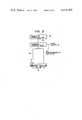
- FIG. 2is a fragmentary view, partly diagrammatic, of a screw tightening apparatus according to another embodiment of the present invention.
- a power-driven screwdrivercomprises a base 1 on which a torque detector 2 is mounted by screws 3.
- the torque detector 2is of a known construction including a central through hole 4 defined by a thin-wall hollow shaft or sleeve 5, and a resistance strain gage 6 attached to an outer peripheral surface thereof.
- the thin-wall sleeve 5is resiliently deformable relatively easily to enable the strain gage 6 to detect a pressure or distortion which the sleeve 5 undergoes.
- An electric motor 7is mounted coaxially on the torque detector 2 and secured thereto by screws 8.
- the motor 7has an output shaft 9 extending concentrically through the hole 4 and rotatably journalled in a bearing 10 mounted in the torque detector 2.
- a screwdriver bit 11is rotatably supported on the base 1 in coaxial relation with the motor shaft 9 and coupled thereto through an electromagnetic clutch 12.
- the electromagnetic clutch 12includes a field coil 19 constituting a field system 20, a rotor 21 coupled concentrically with the motor shaft 9, and an armature 22 axially movably mounted on a flanged support 23 rotatably mounted on the base 1 and supporting the screwdriver bit 11, the flanged support 23 being axially spaced from the rotor 21.
- a compression coil spring 25is disposed around and fixed to the pin 24 and normally urges the armature 22 axially away from the rotor 21 toward the support 23.
- a torque control circuit illustrated in FIG. 1comprises an amplifier 14 for amplifying a signal from the resistance strain gage 6, a comparator 15 for generating an output signal when an amplified signal from the amplifier 14 agrees with a signal supplied from a torque setting device 16 and is indicative of a desired torque with which a screw is to be tightened, a time-delay circuit 17 for delaying the signal from the comparator 15, and a switch 18 responsive to a signal from the time-delay circuit 17 for simultaneously de-energizing the motor 7 and the electromagnetic clutch 12.
- the torque control circuitalso includes an analog-to-digital converter 26 for converting the signal from the amplifier 14 into a corresponding digital signal, and a display unit 27 displaying the digital signal which is indicative of the actual torque with which a screw is tightened.
- An electric power supply 28is connected to the switch 18 to supply an electric current to the motor 7 and the electromagnetic clutch 12 under the control of the switch 18.
- the screwdriver bit 11is brought into engagement with a screw 13 to be driven into a material 29.
- the switch 18is actuated to allow the motor 7 and the electromagnetic clutch 12 to be energized by the power supply 28, whereupon rotative power or tightening torque from the motor 7 is transmitted through the motor shaft 9, the electromagnetic clutch 12, and through the screwdriver bit 11 to the screw 13.
- the tightening torqueis applied as a reactive force to the torque detector 2, causing the thin-wall sleeve 5 to be twisted or distorted.
- the twisted distortion of the thin-wall sleeve 5in turn causes the resistance strain gage 6 to change its electrical resistance and produce a signal proportional to such change in resistance.
- the signal from the strain gage 6is fed through the amplifier 14 to the comparator 15.
- the comparator 15issues an output signal which is delivered to the switch 18 upon elapse of a period of time determined by the time-delay circuit 17.
- the switch 18is responsive to a supplied signal to cut off the electric current from the power supply 28 to the motor 7 and the electromagnetic clutch 12. Therefore, the motor 7 and the electromagnetic clutch 12 are de-energized simultaneously to complete tightening of the screw 13 with a desired torque which is established by the torque setting device 16.
- the tightening torqueis generated after the head of the screw 13 engages the surface of the material 29.
- the period of time required to reach a stable tightening torque after the screw head has seated on the material 29depends on the pitch of the screw 13, the rate of elongation of the screw 13 which varies from material to material, and the rate of contraction of the material 29.
- the tightening timemay be relatively small when hard material such as metal is to be fastened together.
- a longer tightening timeis needed to fasten resilient material such as synthetic resin or rubber packings. Stated otherwise, the resilient objects can be fastened precisely together by holding them for a certain period of time until the elongation of the screw and the contraction of the objects are stabilized.
- the time-delay circuit 17is adjustable so that it can delay the signal from the comparator 15 to keep the motor 7 and the electromagnetic clutch 12 energized for a selected period of time after a desired screw tightening torque has been reached.
- effective and precise screw tighteningcan be effected by adjusting the time-delay circuit 17 dependent on the material of the screw 13 used and the material of the objects to be fastened with the screw 13.
- FIG. 2illustrates a power-driven screwdriver according to another embodiment of the present invention.
- the screwdriveris powered by a pneumatic motor 30 supplied with air under pressure from a source of compressed air 32 such as an air compressor through a solenoid-operated valve 33 which is controlled by the switch 18.
- a source of compressed air 32such as an air compressor
- a solenoid-operated valve 33which is controlled by the switch 18.
- the switch 18de-energizes the solenoid-operated valve 33 to stop the pneumatic motor 30 and at the same time de-energizes the electromagnetic clutch 12.
Landscapes
- Engineering & Computer Science (AREA)
- Mechanical Engineering (AREA)
- Details Of Spanners, Wrenches, And Screw Drivers And Accessories (AREA)
Abstract
Description
Claims (6)
Applications Claiming Priority (2)
| Application Number | Priority Date | Filing Date | Title |
|---|---|---|---|
| JP56-5279 | 1981-01-16 | ||
| JP56005279AJPS57121477A (en) | 1981-01-16 | 1981-01-16 | Fixed torque screw clamping device |
Publications (1)
| Publication Number | Publication Date |
|---|---|
| US4418765Atrue US4418765A (en) | 1983-12-06 |
Family
ID=11606790
Family Applications (1)
| Application Number | Title | Priority Date | Filing Date |
|---|---|---|---|
| US06/338,996Expired - LifetimeUS4418765A (en) | 1981-01-16 | 1982-01-12 | Power-driven screwdriver with a torque control |
Country Status (3)
| Country | Link |
|---|---|
| US (1) | US4418765A (en) |
| JP (1) | JPS57121477A (en) |
| CA (1) | CA1202707A (en) |
Cited By (47)
| Publication number | Priority date | Publication date | Assignee | Title |
|---|---|---|---|---|
| US4501176A (en)* | 1983-06-28 | 1985-02-26 | Lockheed Corporation | Automatic threaded nut installation and torquing system |
| US4502549A (en)* | 1982-03-25 | 1985-03-05 | Robert Bosch Gmbh | Spring-coupled power screwdriver |
| US4613800A (en)* | 1984-09-21 | 1986-09-23 | The Boeing Company | Servo system for measuring and controlling the amount of torque being applied to rotating tools and method |
| US4614134A (en)* | 1983-06-28 | 1986-09-30 | Gewerkschaft Eisenhutte Westfalia | Overload protection system for planetary gear drive |
| US4721169A (en)* | 1986-05-14 | 1988-01-26 | Matsushita Electric Industrial Co., Ltd. | Electric driver with torque-adjustable clutch mechanism |
| US5014793A (en)* | 1989-04-10 | 1991-05-14 | Measurement Specialties, Inc. | Variable speed DC motor controller apparatus particularly adapted for control of portable-power tools |
| US5076120A (en)* | 1990-10-31 | 1991-12-31 | Lin Pi Chu | Electric wrench |
| US5113949A (en)* | 1988-10-12 | 1992-05-19 | Fuji Kuuki Kabushiki Kaisha | Tightening control apparatus for a torque wrench |
| US5117919A (en)* | 1989-09-11 | 1992-06-02 | The Rotor Tool Company | Torque control system and method |
| US5181575A (en)* | 1991-03-07 | 1993-01-26 | Nissan Morot Co., Ltd. | Impact wrench having torque controlling faculty |
| US5366026A (en)* | 1992-08-28 | 1994-11-22 | Nissan Motor Company, Ltd. | Impact type clamping apparatus |
| US5725533A (en)* | 1990-03-09 | 1998-03-10 | Nobel Biocare Ab | Torsional tightener for bone anchoring or implant elements/tools |
| WO1998022263A1 (en)* | 1996-11-19 | 1998-05-28 | Hohmann Joerg | Power wrench |
| US6263742B1 (en)* | 1997-11-17 | 2001-07-24 | Serac Group | Method of controlling a screwing spindle |
| US6675596B2 (en)* | 2001-04-24 | 2004-01-13 | Nippon Soken, Inc. | Compressor driven selectively by first and second drive sources |
| US6763564B2 (en) | 2002-04-04 | 2004-07-20 | Lakewood Engineering And Manufacturing Co. | Automated method and apparatus for driving fasteners into an electric fan assembly |
| US20090139822A1 (en)* | 2007-11-30 | 2009-06-04 | Sehan Electools., Ltd | Torque-controlling actuator clutch and tool system having the same |
| KR100944454B1 (en) | 2007-11-30 | 2010-03-03 | 주식회사 세한전동 | Actuator clutch for torque control and electric driver device having same |
| CN102022452A (en)* | 2009-08-31 | 2011-04-20 | 世韩电动株式会社 | Torque control transmission device clutch and tool system with same |
| KR101095150B1 (en) | 2009-03-12 | 2011-12-16 | 서종철 | Maximum speed control device of air tool rotor |
| US20110315414A1 (en)* | 2010-06-23 | 2011-12-29 | Hilti Aktiengesellschaft | Screwdriver and control method |
| US20120090863A1 (en)* | 2010-01-07 | 2012-04-19 | Daniel Puzio | Screwdriving tool having a driving tool with a removable contact trip assembly |
| CN101786178B (en)* | 2009-01-22 | 2012-10-03 | 苏州宝时得电动工具有限公司 | Electric tool |
| US8286723B2 (en) | 2010-01-07 | 2012-10-16 | Black & Decker Inc. | Power screwdriver having rotary input control |
| US8418778B2 (en) | 2010-01-07 | 2013-04-16 | Black & Decker Inc. | Power screwdriver having rotary input control |
| USRE44311E1 (en) | 2004-10-20 | 2013-06-25 | Black & Decker Inc. | Power tool anti-kickback system with rotational rate sensor |
| USD703017S1 (en) | 2011-01-07 | 2014-04-22 | Black & Decker Inc. | Screwdriver |
| US8851201B2 (en) | 2008-08-06 | 2014-10-07 | Milwaukee Electric Tool Corporation | Precision torque tool |
| US8919456B2 (en) | 2012-06-08 | 2014-12-30 | Black & Decker Inc. | Fastener setting algorithm for drill driver |
| US9193055B2 (en) | 2012-04-13 | 2015-11-24 | Black & Decker Inc. | Electronic clutch for power tool |
| US9266178B2 (en) | 2010-01-07 | 2016-02-23 | Black & Decker Inc. | Power tool having rotary input control |
| US9289886B2 (en) | 2010-11-04 | 2016-03-22 | Milwaukee Electric Tool Corporation | Impact tool with adjustable clutch |
| CN105451943A (en)* | 2013-08-08 | 2016-03-30 | 阿特拉斯·科普柯工业技术公司 | Torque delivering power tool with flywheel |
| US9475180B2 (en) | 2010-01-07 | 2016-10-25 | Black & Decker Inc. | Power tool having rotary input control |
| CN104485860B (en)* | 2009-01-04 | 2017-08-22 | 苏州宝时得电动工具有限公司 | The control method of electric tool and the electric tool for performing the control method |
| US9908182B2 (en) | 2012-01-30 | 2018-03-06 | Black & Decker Inc. | Remote programming of a power tool |
| US20180193993A1 (en)* | 2017-01-09 | 2018-07-12 | Tricord Solutions, Inc. | Compact Impacting Apparatus |
| US10483901B2 (en) | 2017-07-10 | 2019-11-19 | Newfrey Llc | System and method for installation and verification of fasteners |
| TWI677408B (en)* | 2017-12-08 | 2019-11-21 | 日商肯耐克科技股份有限公司 | Tool, operation management device, operation management method and operation management system |
| US10589413B2 (en) | 2016-06-20 | 2020-03-17 | Black & Decker Inc. | Power tool with anti-kickback control system |
| US20210370450A1 (en)* | 2020-05-27 | 2021-12-02 | Konica Minolta, Inc. | Screw tightening apparatus and screw tightening method |
| US20220250211A1 (en)* | 2021-02-10 | 2022-08-11 | Jackco Transnational Inc. | Electric vise |
| US20240227148A9 (en)* | 2021-04-16 | 2024-07-11 | Black & Decker Inc. | Electrostatic clutch for power tool |
| US12044530B2 (en) | 2008-07-10 | 2024-07-23 | Black & Decker Inc. | Communication protocol for remotely controlled laser devices |
| US12122028B2 (en) | 2022-05-26 | 2024-10-22 | Milwaukee Electric Tool Corporation | Electronic clutch for powered fastener driver |
| US12318906B2 (en) | 2012-06-08 | 2025-06-03 | Black & Decker Inc. | Power tool having multiple operating modes |
| US12434371B2 (en) | 2022-03-23 | 2025-10-07 | Milwaukee Electric Tool Corporation | Electronic clutch for power tools |
Families Citing this family (5)
| Publication number | Priority date | Publication date | Assignee | Title |
|---|---|---|---|---|
| JPS59196134A (en)* | 1983-04-18 | 1984-11-07 | Matsushita Electric Ind Co Ltd | screw tightening device |
| JPS6039468U (en)* | 1983-08-24 | 1985-03-19 | 油谷鉄工株式会社 | pneumatic tools |
| JPH02116479A (en)* | 1988-10-21 | 1990-05-01 | Fujitsu Ltd | screw tightening device |
| JPH0379279A (en)* | 1989-08-15 | 1991-04-04 | Hayashi Tokei Kogyo Kk | Motor driver |
| EP2030709A3 (en) | 2007-08-29 | 2013-01-16 | Positec Power Tools (Suzhou) Co., Ltd. | Power tool |
Citations (1)
| Publication number | Priority date | Publication date | Assignee | Title |
|---|---|---|---|---|
| US3825912A (en)* | 1973-07-12 | 1974-07-23 | Gen Motors Corp | Torque wrench monitor |
Family Cites Families (4)
| Publication number | Priority date | Publication date | Assignee | Title |
|---|---|---|---|---|
| JPS502300A (en)* | 1973-05-14 | 1975-01-10 | ||
| JPS5822312B2 (en)* | 1976-01-28 | 1983-05-07 | エスピ−エス テクノロジ−ズ・インコ−ポレ−テッド | Tightening device for tightening fasteners |
| JPS533840A (en)* | 1976-06-30 | 1978-01-13 | Nec Corp | Infrared ray dark field observation device |
| JPS605428B2 (en)* | 1977-12-23 | 1985-02-12 | 勝行 戸津 | Control method for clutch-type electric rotary tools |
- 1981
- 1981-01-16JPJP56005279Apatent/JPS57121477A/enactiveGranted
- 1982
- 1982-01-12USUS06/338,996patent/US4418765A/ennot_activeExpired - Lifetime
- 1982-01-15CACA000394245Apatent/CA1202707A/ennot_activeExpired
Patent Citations (1)
| Publication number | Priority date | Publication date | Assignee | Title |
|---|---|---|---|---|
| US3825912A (en)* | 1973-07-12 | 1974-07-23 | Gen Motors Corp | Torque wrench monitor |
Cited By (62)
| Publication number | Priority date | Publication date | Assignee | Title |
|---|---|---|---|---|
| US4502549A (en)* | 1982-03-25 | 1985-03-05 | Robert Bosch Gmbh | Spring-coupled power screwdriver |
| US4614134A (en)* | 1983-06-28 | 1986-09-30 | Gewerkschaft Eisenhutte Westfalia | Overload protection system for planetary gear drive |
| US4501176A (en)* | 1983-06-28 | 1985-02-26 | Lockheed Corporation | Automatic threaded nut installation and torquing system |
| US4613800A (en)* | 1984-09-21 | 1986-09-23 | The Boeing Company | Servo system for measuring and controlling the amount of torque being applied to rotating tools and method |
| US4721169A (en)* | 1986-05-14 | 1988-01-26 | Matsushita Electric Industrial Co., Ltd. | Electric driver with torque-adjustable clutch mechanism |
| US5113949A (en)* | 1988-10-12 | 1992-05-19 | Fuji Kuuki Kabushiki Kaisha | Tightening control apparatus for a torque wrench |
| US5014793A (en)* | 1989-04-10 | 1991-05-14 | Measurement Specialties, Inc. | Variable speed DC motor controller apparatus particularly adapted for control of portable-power tools |
| US5117919A (en)* | 1989-09-11 | 1992-06-02 | The Rotor Tool Company | Torque control system and method |
| US5725533A (en)* | 1990-03-09 | 1998-03-10 | Nobel Biocare Ab | Torsional tightener for bone anchoring or implant elements/tools |
| US5076120A (en)* | 1990-10-31 | 1991-12-31 | Lin Pi Chu | Electric wrench |
| US5181575A (en)* | 1991-03-07 | 1993-01-26 | Nissan Morot Co., Ltd. | Impact wrench having torque controlling faculty |
| US5366026A (en)* | 1992-08-28 | 1994-11-22 | Nissan Motor Company, Ltd. | Impact type clamping apparatus |
| WO1998022263A1 (en)* | 1996-11-19 | 1998-05-28 | Hohmann Joerg | Power wrench |
| US6161629A (en)* | 1996-11-19 | 2000-12-19 | Hohmann; Joerg | Power wrench |
| US6263742B1 (en)* | 1997-11-17 | 2001-07-24 | Serac Group | Method of controlling a screwing spindle |
| US6675596B2 (en)* | 2001-04-24 | 2004-01-13 | Nippon Soken, Inc. | Compressor driven selectively by first and second drive sources |
| US6763564B2 (en) | 2002-04-04 | 2004-07-20 | Lakewood Engineering And Manufacturing Co. | Automated method and apparatus for driving fasteners into an electric fan assembly |
| USRE44311E1 (en) | 2004-10-20 | 2013-06-25 | Black & Decker Inc. | Power tool anti-kickback system with rotational rate sensor |
| USRE45112E1 (en) | 2004-10-20 | 2014-09-09 | Black & Decker Inc. | Power tool anti-kickback system with rotational rate sensor |
| USRE44993E1 (en) | 2004-10-20 | 2014-07-08 | Black & Decker Inc. | Power tool anti-kickback system with rotational rate sensor |
| US20090139822A1 (en)* | 2007-11-30 | 2009-06-04 | Sehan Electools., Ltd | Torque-controlling actuator clutch and tool system having the same |
| KR100944454B1 (en) | 2007-11-30 | 2010-03-03 | 주식회사 세한전동 | Actuator clutch for torque control and electric driver device having same |
| US12044530B2 (en) | 2008-07-10 | 2024-07-23 | Black & Decker Inc. | Communication protocol for remotely controlled laser devices |
| US8851201B2 (en) | 2008-08-06 | 2014-10-07 | Milwaukee Electric Tool Corporation | Precision torque tool |
| CN104485860B (en)* | 2009-01-04 | 2017-08-22 | 苏州宝时得电动工具有限公司 | The control method of electric tool and the electric tool for performing the control method |
| CN101786178B (en)* | 2009-01-22 | 2012-10-03 | 苏州宝时得电动工具有限公司 | Electric tool |
| KR101095150B1 (en) | 2009-03-12 | 2011-12-16 | 서종철 | Maximum speed control device of air tool rotor |
| CN102022452A (en)* | 2009-08-31 | 2011-04-20 | 世韩电动株式会社 | Torque control transmission device clutch and tool system with same |
| US9321156B2 (en) | 2010-01-07 | 2016-04-26 | Black & Decker Inc. | Power tool having rotary input control |
| US9415488B2 (en) | 2010-01-07 | 2016-08-16 | Black & Decker Inc. | Screwdriving tool having a driving tool with a removable contact trip assembly |
| US20120090863A1 (en)* | 2010-01-07 | 2012-04-19 | Daniel Puzio | Screwdriving tool having a driving tool with a removable contact trip assembly |
| US8875804B2 (en)* | 2010-01-07 | 2014-11-04 | Black & Decker Inc. | Screwdriving tool having a driving tool with a removable contact trip assembly |
| US8418778B2 (en) | 2010-01-07 | 2013-04-16 | Black & Decker Inc. | Power screwdriver having rotary input control |
| US8286723B2 (en) | 2010-01-07 | 2012-10-16 | Black & Decker Inc. | Power screwdriver having rotary input control |
| US9199362B2 (en) | 2010-01-07 | 2015-12-01 | Black & Decker Inc. | Power tool having rotary input control |
| US9211636B2 (en) | 2010-01-07 | 2015-12-15 | Black & Decker Inc. | Power tool having rotary input control |
| US9266178B2 (en) | 2010-01-07 | 2016-02-23 | Black & Decker Inc. | Power tool having rotary input control |
| US9475180B2 (en) | 2010-01-07 | 2016-10-25 | Black & Decker Inc. | Power tool having rotary input control |
| US9321155B2 (en) | 2010-01-07 | 2016-04-26 | Black & Decker Inc. | Power tool having switch and rotary input control |
| US10160049B2 (en) | 2010-01-07 | 2018-12-25 | Black & Decker Inc. | Power tool having rotary input control |
| US20110315414A1 (en)* | 2010-06-23 | 2011-12-29 | Hilti Aktiengesellschaft | Screwdriver and control method |
| US9289886B2 (en) | 2010-11-04 | 2016-03-22 | Milwaukee Electric Tool Corporation | Impact tool with adjustable clutch |
| USD703017S1 (en) | 2011-01-07 | 2014-04-22 | Black & Decker Inc. | Screwdriver |
| US11712741B2 (en) | 2012-01-30 | 2023-08-01 | Black & Decker Inc. | Remote programming of a power tool |
| US9908182B2 (en) | 2012-01-30 | 2018-03-06 | Black & Decker Inc. | Remote programming of a power tool |
| US9193055B2 (en) | 2012-04-13 | 2015-11-24 | Black & Decker Inc. | Electronic clutch for power tool |
| US10220500B2 (en) | 2012-04-13 | 2019-03-05 | Black & Decker Inc. | Electronic clutch for power tool |
| US12318906B2 (en) | 2012-06-08 | 2025-06-03 | Black & Decker Inc. | Power tool having multiple operating modes |
| US8919456B2 (en) | 2012-06-08 | 2014-12-30 | Black & Decker Inc. | Fastener setting algorithm for drill driver |
| CN105451943A (en)* | 2013-08-08 | 2016-03-30 | 阿特拉斯·科普柯工业技术公司 | Torque delivering power tool with flywheel |
| US10589413B2 (en) | 2016-06-20 | 2020-03-17 | Black & Decker Inc. | Power tool with anti-kickback control system |
| US11192232B2 (en) | 2016-06-20 | 2021-12-07 | Black & Decker Inc. | Power tool with anti-kickback control system |
| US20180193993A1 (en)* | 2017-01-09 | 2018-07-12 | Tricord Solutions, Inc. | Compact Impacting Apparatus |
| US10771004B2 (en) | 2017-07-10 | 2020-09-08 | Newfrey Llc | System and method for installation and verification of fasteners |
| US10483901B2 (en) | 2017-07-10 | 2019-11-19 | Newfrey Llc | System and method for installation and verification of fasteners |
| TWI677408B (en)* | 2017-12-08 | 2019-11-21 | 日商肯耐克科技股份有限公司 | Tool, operation management device, operation management method and operation management system |
| US20210370450A1 (en)* | 2020-05-27 | 2021-12-02 | Konica Minolta, Inc. | Screw tightening apparatus and screw tightening method |
| US11478887B2 (en)* | 2020-05-27 | 2022-10-25 | Konica Minolta, Inc. | Screw tightening apparatus and screw tightening method |
| US20220250211A1 (en)* | 2021-02-10 | 2022-08-11 | Jackco Transnational Inc. | Electric vise |
| US20240227148A9 (en)* | 2021-04-16 | 2024-07-11 | Black & Decker Inc. | Electrostatic clutch for power tool |
| US12434371B2 (en) | 2022-03-23 | 2025-10-07 | Milwaukee Electric Tool Corporation | Electronic clutch for power tools |
| US12122028B2 (en) | 2022-05-26 | 2024-10-22 | Milwaukee Electric Tool Corporation | Electronic clutch for powered fastener driver |
Also Published As
| Publication number | Publication date |
|---|---|
| CA1202707A (en) | 1986-04-01 |
| JPH0230832B2 (en) | 1990-07-10 |
| JPS57121477A (en) | 1982-07-28 |
Similar Documents
| Publication | Publication Date | Title |
|---|---|---|
| US4418765A (en) | Power-driven screwdriver with a torque control | |
| US4095325A (en) | Method for tightening bolts | |
| US5154242A (en) | Power tools with multi-stage tightening torque control | |
| US4709182A (en) | Method and apparatus for tightening or loosening screw-type connections | |
| CA1053928A (en) | Apparatus for and method of determining rotational or linear stiffness | |
| US4273198A (en) | Motor-driven clamping method and device | |
| JP2957838B2 (en) | Apparatus and method for compensating torque overshoot of power tool | |
| US4987806A (en) | Electronic control circuitry for a nutrunner | |
| CN107538209B (en) | Bolt locking device and control method thereof | |
| CA2008512A1 (en) | Method and apparatus for determining load holding torque | |
| CN101422824A (en) | Method and device for balancing centrifugal force in a machine tool with an electrospanner | |
| US4173059A (en) | Device for tightening bolts | |
| US7467669B2 (en) | Method for governing the operation of a pneumatic impulse wrench and a power screw joint tightening tool system | |
| CN109175988A (en) | A kind of fastener is adjusted torsion device for screwing up and tightens force control method | |
| US6421902B1 (en) | Method and device for producing and checking screwed connections | |
| US2562831A (en) | Bolt or stud tightener | |
| JPH0592300A (en) | Motor-driven pressing method | |
| US4597150A (en) | Method of and apparatus for closing joint devices to obtain consistent torque values | |
| EP0266066B1 (en) | Power tool | |
| EP0271902A2 (en) | Method of and apparatus for tightening screw-threaded fasteners | |
| JPS6213147B2 (en) | ||
| KR200492689Y1 (en) | Torque adjusting assembly for electric screwdriver | |
| JP3307158B2 (en) | Screw fastening device | |
| CN209157637U (en) | A kind of adjustable torsion device for screwing up of fastener | |
| JP2688810B2 (en) | Screw tightening method and screw tightening device used for implementing this method |
Legal Events
| Date | Code | Title | Description |
|---|---|---|---|
| AS | Assignment | Owner name:MATSUSHITA ELECTRIC COMPANY, LIMITED; 1006, OAZA K Free format text:ASSIGNMENT OF ASSIGNORS INTEREST.;ASSIGNORS:MORI, TAKASHI;HOSOKAWA, SHUUJI;NAITO, TAKAO;REEL/FRAME:003965/0015 Effective date:19820105 | |
| STCF | Information on status: patent grant | Free format text:PATENTED CASE | |
| MAFP | Maintenance fee payment | Free format text:PAYMENT OF MAINTENANCE FEE, 4TH YEAR, PL 96-517 (ORIGINAL EVENT CODE: M170); ENTITY STATUS OF PATENT OWNER: LARGE ENTITY Year of fee payment:4 | |
| FEPP | Fee payment procedure | Free format text:PAYOR NUMBER ASSIGNED (ORIGINAL EVENT CODE: ASPN); ENTITY STATUS OF PATENT OWNER: LARGE ENTITY | |
| MAFP | Maintenance fee payment | Free format text:PAYMENT OF MAINTENANCE FEE, 8TH YEAR, PL 96-517 (ORIGINAL EVENT CODE: M171); ENTITY STATUS OF PATENT OWNER: LARGE ENTITY Year of fee payment:8 | |
| FEPP | Fee payment procedure | Free format text:PAYOR NUMBER ASSIGNED (ORIGINAL EVENT CODE: ASPN); ENTITY STATUS OF PATENT OWNER: LARGE ENTITY Free format text:PAYER NUMBER DE-ASSIGNED (ORIGINAL EVENT CODE: RMPN); ENTITY STATUS OF PATENT OWNER: LARGE ENTITY | |
| MAFP | Maintenance fee payment | Free format text:PAYMENT OF MAINTENANCE FEE, 12TH YEAR, LARGE ENTITY (ORIGINAL EVENT CODE: M185); ENTITY STATUS OF PATENT OWNER: LARGE ENTITY Year of fee payment:12 |