US4418310A - Battery charger control circuit - Google Patents
Battery charger control circuitDownload PDFInfo
- Publication number
- US4418310A US4418310AUS06/322,333US32233381AUS4418310AUS 4418310 AUS4418310 AUS 4418310AUS 32233381 AUS32233381 AUS 32233381AUS 4418310 AUS4418310 AUS 4418310A
- Authority
- US
- United States
- Prior art keywords
- battery
- voltage
- average
- battery voltage
- circuit
- Prior art date
- Legal status (The legal status is an assumption and is not a legal conclusion. Google has not performed a legal analysis and makes no representation as to the accuracy of the status listed.)
- Expired - Lifetime
Links
- 230000001105regulatory effectEffects0.000claimsabstractdescription9
- 230000001276controlling effectEffects0.000claims1
- 238000012544monitoring processMethods0.000abstract1
- 238000010586diagramMethods0.000description20
- 239000003990capacitorSubstances0.000description15
- 230000007423decreaseEffects0.000description6
- 238000012935AveragingMethods0.000description4
- 239000002253acidSubstances0.000description3
- 230000001960triggered effectEffects0.000description3
- QVGXLLKOCUKJST-UHFFFAOYSA-Natomic oxygenChemical compound[O]QVGXLLKOCUKJST-UHFFFAOYSA-N0.000description2
- 238000001514detection methodMethods0.000description2
- 238000005259measurementMethods0.000description2
- 239000001301oxygenSubstances0.000description2
- 229910052760oxygenInorganic materials0.000description2
- 238000004904shorteningMethods0.000description2
- UFHFLCQGNIYNRP-UHFFFAOYSA-NHydrogenChemical compound[H][H]UFHFLCQGNIYNRP-UHFFFAOYSA-N0.000description1
- 230000002159abnormal effectEffects0.000description1
- 230000002411adverseEffects0.000description1
- 230000002238attenuated effectEffects0.000description1
- 230000008878couplingEffects0.000description1
- 238000010168coupling processMethods0.000description1
- 238000005859coupling reactionMethods0.000description1
- 230000002950deficientEffects0.000description1
- 230000005611electricityEffects0.000description1
- 238000005868electrolysis reactionMethods0.000description1
- 239000003792electrolyteSubstances0.000description1
- 238000010438heat treatmentMethods0.000description1
- 239000001257hydrogenSubstances0.000description1
- 229910052739hydrogenInorganic materials0.000description1
- 230000036039immunityEffects0.000description1
- 238000000034methodMethods0.000description1
- 238000005070samplingMethods0.000description1
- 230000000007visual effectEffects0.000description1
Images


Classifications
- H—ELECTRICITY
- H02—GENERATION; CONVERSION OR DISTRIBUTION OF ELECTRIC POWER
- H02J—CIRCUIT ARRANGEMENTS OR SYSTEMS FOR SUPPLYING OR DISTRIBUTING ELECTRIC POWER; SYSTEMS FOR STORING ELECTRIC ENERGY
- H02J7/00—Circuit arrangements for charging or depolarising batteries or for supplying loads from batteries
- H02J7/007—Regulation of charging or discharging current or voltage
- H02J7/00712—Regulation of charging or discharging current or voltage the cycle being controlled or terminated in response to electric parameters
- H02J7/007182—Regulation of charging or discharging current or voltage the cycle being controlled or terminated in response to electric parameters in response to battery voltage
- H02J7/007184—Regulation of charging or discharging current or voltage the cycle being controlled or terminated in response to electric parameters in response to battery voltage in response to battery voltage gradient
- Y—GENERAL TAGGING OF NEW TECHNOLOGICAL DEVELOPMENTS; GENERAL TAGGING OF CROSS-SECTIONAL TECHNOLOGIES SPANNING OVER SEVERAL SECTIONS OF THE IPC; TECHNICAL SUBJECTS COVERED BY FORMER USPC CROSS-REFERENCE ART COLLECTIONS [XRACs] AND DIGESTS
- Y10—TECHNICAL SUBJECTS COVERED BY FORMER USPC
- Y10S—TECHNICAL SUBJECTS COVERED BY FORMER USPC CROSS-REFERENCE ART COLLECTIONS [XRACs] AND DIGESTS
- Y10S320/00—Electricity: battery or capacitor charging or discharging
- Y10S320/13—Fault detection
- Y—GENERAL TAGGING OF NEW TECHNOLOGICAL DEVELOPMENTS; GENERAL TAGGING OF CROSS-SECTIONAL TECHNOLOGIES SPANNING OVER SEVERAL SECTIONS OF THE IPC; TECHNICAL SUBJECTS COVERED BY FORMER USPC CROSS-REFERENCE ART COLLECTIONS [XRACs] AND DIGESTS
- Y10—TECHNICAL SUBJECTS COVERED BY FORMER USPC
- Y10S—TECHNICAL SUBJECTS COVERED BY FORMER USPC CROSS-REFERENCE ART COLLECTIONS [XRACs] AND DIGESTS
- Y10S320/00—Electricity: battery or capacitor charging or discharging
- Y10S320/25—Optical coupler
Definitions
- This inventionrelates to an electronic battery charger control circuit. More particularly, this invention relates to a control circuit for a battery charger of the type designed to recharge lead acid batteries such as used in supplying power to electric vehicles, and for terminating the charging operation whenever the batteries are fully charged.
- the first reasonhas to do with the cost of electricity. Obviously, if a battery charger is operated beyond the point where the battery is fully charged, it is wasting energy and money. On the other hand, it is important that the battery become fully charged, otherwise it will not be ready for a full day's operation.
- One typical prior art battery charger control circuitis essentially a timer which applies charging current to the battery for a specified period of time. If it is assumed that a battery becomes 80% or 90% discharged during the course of a typical 8-hour shift, and if the battery and the battery charger capacity are properly selected, then an 8-hour charge will usually put the battery back into condition for the next shift. However, if the battery is only 20% discharged, then a shortened charging time would be indicated, and if it were 100% discharged, then a longer charging time would be required.
- a voltage relayis used to sense the battery voltage, and when it has reached a predetermined level, to terminate the charging cycle. If the battery is defective in some way, the battery voltage might never reach the predetermined value.
- the rate of change of battery voltageis used as a measure of the state of charge.
- variations in charging voltage, or noise on the output of the battery chargerwould adversely affect this type of measurement device, thus either shortening or prolonging the charging cycle.
- This inventionrelates to an automatic battery charging apparatus wherein charging current to the battery will be terminated after the battery has become fully charged.
- Battery charging currentis provided by a regulated source of current, and both the voltage and the current output of the regulator are monitored by a control circuit.
- the actual voltage on the batteryis measured as an indication of the state of charge, and when the rate of voltage change decreases, indicating the approach of a fully charged condition, the charging operation will thereafter be terminated.
- This inventiondiffers from the prior art in that the battery voltage is averaged over a period of time sufficient to ensure that momentary variations in the charger output voltage as well as ripple and other line noises are effectively filtered out, and that several consecutive average voltage measurements of less than a predetermined voltage are required before the charging operation is terminated.
- an averaging analog to digital converterprovides a digital output representative of the average battery voltage taken over a predetermined interval of time. The average voltage is then monitored at regular intervals, and the current reading is compared to a previous reading. If a predetermined number of consecutive comparisons reveals that there is a change in battery voltage of less than a predetermined amount, then a control signal is generated to disconnect the source of charging current to the battery.
- the predetermined change in battery voltage required before terminationis selected on the basis of the percent of recharge desired. In the preferred embodiment, a voltage change of less than 270 microvolts per minute per cell would indicate a recharge condition of 107% of the discharge ampere hours.
- termination within five to ten minutes after reaching a fully charged conditionis substantially immediate, considering that a typical charging cycle is about eight hours in duration. This length of time allows several average battery voltage readings to be made, each average taken over a period of time long enough to ensure that momentary variations in charge output voltage may be ignored, and also to provide substantial noise immunity.
- Requiring a plurality of consecutive voltage change indications of less than a predetermined amountalso ensures or provides reliability and consistent operation of the charger. In a preferred embodiment, therefore, it will take over just four and a half minutes to terminate the charging operation once a fully charged condition has been indicated. This assures also that the change in voltage is due to the condition of the battery, and not arbitrary changes due to variations in the line voltage which is applied to the regulated charger.
- It is therefore an object of this invention to provide an automatic battery charging apparatusincluding means for providing a source of regulated electrical current for charging the battery, means for sensing the average battery voltage at regular intervals, means for comparing successive average battery voltage readings, means responsive to a predetermined number of consecutive comparisons of average battery voltage readings wherein the difference in the voltage measured is of less than a predetermined amount for generating a control signal, and means responsive to the control signal for disconnecting the source of charging current from the battery.
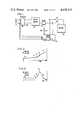
- FIG. 1is a generalized block diagram showing the arrangement of components used according to this invention to charge a battery
- FIG. 2is a curve showing the relationship between the voltage of a battery as it is being charged with respect to time
- FIG. 3is a curve showing the voltage rate of change of a battery undergoing charge with respect to time
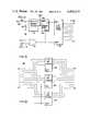
- FIG. 4is a block diagram showing the relationship of the components which comprise a control circuit constructed according to this invention.
- FIG. 5is a block diagram of a clock which provides timing signals used by the control circuit
- FIG. 6is a timing chart illustrating the various output signals from the clock of FIG. 5;
- FIG. 7is an electrical schematic diagram of a voltage divider, low pass filter and offset amplifier used in connection with this invention.
- FIG. 8is an electrical schematic diagram showing a 2.4 volt per cell level detector
- FIG. 9is a simplified block diagram of an averaging analog to digital converter
- FIG. 10is a block diagram of a single word storage register
- FIG. 11is a block diagram of a digital comparer
- FIG. 12is a block diagram showing a consecutive sample circuit
- FIG. 13is a schematic diagram of a counter circuit
- FIG. 14is an electrical schematic diagram of an alternating current failure detector circuit
- FIG. 15is an electrical schematic diagram of a current amplifier and comparator circuit
- FIG. 16is a schematic diagram of the termination logic circuit.
- a battery 10is connected by wires 12 and 14 to a regulated battery charger 15.
- the charging currentis monitored by a shunt 17 which is connected to control circuit 20 by wires 21 and 22.
- the charger 15is preferably a regulated charger having a controlled output, such as the type described in U.S. Pat. No. 4,130,790. It is preferred that the charger be regulated to within one percent output voltage for as much as a ten percent change in the charger input voltage.
- the battery charger 15is connected to a source of alternating current power through a contactor 25, the operation of which is controlled by the circuit 20.
- the charging curve of a lead acid batteryis well known and is illustrated in FIGS. 2 and 3. As a lead acid battery becomes fully charged, the voltage rate of change decreases noticeably, and if means could be provided to sense when this decrease in voltage rate of change occurs, the charging operation could be terminated, thus saving the batteries from being overcharged, and also providing considerable savings in the cost of maintaining the batteries.
- the battery voltageincreases slowly from time T0 to time T1, and thereafter increases at a rapid rate until time T3, at which time the rate of battery change decreases, and when the rate of change decreases below a predetermined level, at T4, then the charging operation will be terminated.
- the control circuit 20includes means for sensing the battery voltage at regular intervals and further means for disconnecting the source of charging current from the battery whenever the rate of charge decreases below the aforesaid predetermined level.
- the control circuitalso includes means for terminating the battery charger operation whenever the battery is disconnected and means for allowing the operator to manually interrupt the charging operation.
- the control circuitis shown in block diagram form in FIG. 4.
- This circuitincludes a voltage divider, low pass filter and offset amplifier circuit 30 having an input connected to the battery by means of wires 12 and 14. Also connected to the battery is a 2.4 volt per cell level detector circuit 35.
- a source of commercial AC poweris connected to a clock circuit 40, and the clock provides several outputs which control the timing of the remainder of the control circuit 20.
- the current shunt 17is connected to a current amplifier and comparator circuit 45 by wires 21 and 22.
- the control circuit 20includes means for providing a digital output representative of average battery voltage taken over a predetermined period of time, and in the preferred embodiment of the invention, this means is in the form of an 11 bit averaging analog to digital converter 50 that provides a digital output to a single word storage register 55.
- the control circuitalso includes means for comparing successive average battery voltage readings, and this preferably is in the form of a digital comparator circuit 60 that compares the output from the single word storage register 55, representing the previous average battery voltage reading, with the present average voltage reading from the A/D converter 50.
- the control circuitfurther includes means responsive to a predetermined number of consecutive comparisons of average battery voltage readings wherein the difference in voltage is less than a predetermined amount for generating a control signal.
- This meansis in the form of a consecutive sample circuit 65. It receives as its input a signal from an output of the digital comparator 60 indicating that the difference between the present battery voltage and the previous battery voltage signal is less than a predetermined amount.
- an ouput control signalis provided to a termination logic circuit 70 to cause the AC line contactor 25 to disconnect the source of charging current from the battery 10.
- the 60 cycle source of alternating current for the battery charger 15is also coupled to the clock 40 through a photon-coupled transistor 100, one output of which is applied on line 105 directly to the ⁇ 6 terminal. As shown in FIG. 6, the ⁇ 6 output is a series of 60 cycle square wave pulses.
- the photon-coupled transistoris also connected to a frequency divider circuit 110, which provides one output pulse for every 4096 input pulses, or in other words, each 1.14 minutes (T6).
- the output on line 115is applied directly to the ⁇ 5 terminal and also through a coupling capacitor C1 to a monostable multivibrator 120, the output of which on line 125 is applied to the ⁇ 1 terminal and also to a 50 millisecond delay circuit 30 whose output is applied to the ⁇ 2 terminal.
- the output of the multivibrator 120is also applied through a capacitor C2 to a second monostable multivibrator 135, whose output is applied directly to the ⁇ 3 terminal and through capacitor C3 to a third monostable multivbrator 140, which provides the ⁇ 4 output.
- Each of the monostable multivibrators 120, 135 and 140are triggered upon the trailing edge of the respective input pulse, and each generate a pulse having a width T5 of approximately 100 milliseconds in length.
- the trailing edge of the ⁇ 5 signal from the frequency to divider 110triggers multivibrator 120, which provides the ⁇ 1 output.
- the ⁇ 2 outputis a 50 millisecond delay signal provided by the circuit 130.
- the trailing edge of the ⁇ 1 outputtriggers monostable 135, which provides the ⁇ 3 output, and the trailing edge of the ⁇ 3 pulse triggers monostable 140, which provides the ⁇ 4 output.
- each of the ⁇ 1, ⁇ 2, ⁇ 3, ⁇ 4 and ⁇ 5 outputsare of the same frequency, but the output pulses appearing thereon appear at different times. These timing pulses are used to control the sequence of operation of the various circuits which comprise the control circuit 20 shown in FIG. 4.
- FIG. 7illustrates a voltage divider, low-pass filter and offset amplifier circuit 30
- the voltage across the battery 10is applied to a voltage divider network comprising resistor R4 and potentiometer R5, and a portion of that voltage is taken from the wiper of potentiometer R5 and applied to amplifier U1, an operational amplifier connected in a buffer configuration.
- the low-pass filter portion of this circuitincludes capacitor C4 which is connected between the input of the amplifier and ground.
- resistor R4 and the setting of potentiometer R5are selected to provide an output from amplifier U1 which represents two times the battery voltage divided by the number of cells in the battery.
- the battery cell voltage of interestis between 2.4 and 2.65 volts-per-cell, and therefore the input to resistor R6 connected to the positive terminal of the offset amplifier U2 will range from 4.8 to 5.3 volts.
- the input to resistor R7is a reference voltage of 4.7 volts obtained from the wiper of potentiometer R8 which has its input connected to a temperature compensated, calibrated 5 volt reference source.
- the amplifier U2is connected as a differential amplifier to provide a gain of approximately 16 (R9/R7) and its output VO on line 32 is applied as an input to the analog to digital converter 50.
- the circuit of FIG. 7is therefore a means for applying to the remainder of the circuit a signal representative of battery voltage but expanded in the range of battery voltages of particular interest.
- battery voltages of less than 2.4 volts-per-cellare not of interest, since they indicate a battery in a discharged condition, and it is unlikely that battery voltages will exceed 2.65 volts-per-cell. Therefore, the range of voltages VO on line 32 will vary from 0 to 10 volts to represent a change of 0.30 volts-per-cell at the battery.
- FIG. 8is a schematic diagram of the voltage level detector 35. This circuit provides an output whenever the battery voltage represents an average of 2.4 volts-per-cell or above. As in FIG. 7, the battery is connected between terminals 12 and 14, and a voltage divider network including resistor R11 and potentiometer R12 takes a portion of that voltage and applies it as an input to the amplifier U3 which is an operational amplifier connected as a comparator. Capacitor C5 acts as a low-pass filter to smooth the input to the amplifier. A reference voltage is provided through resistor R13, and a feedback is provided through resistor R14.
- the output of the amplifier U3is low, or 0 volts, until the voltage at the wiper of potentiometer R12 exceeds the reference, or until the average battery voltage exceeds 2.4 volts-per-cell. When this condition is met, the output on line 37 will go high, or to 12 volts, indicating that the condition has been met. This output is applied on line 37 to the termination logic circuit 70.
- FIG. 9is a block diagram of the averaging analog to digital converter circuit 50 which accepts an expanded analog input VO on line 32 and applies this voltage through a low-pass filter, including resistor R15 and capacitor C6, to a voltage-to-frequency converter circuit 51.
- the voltage to frequency converterprovides a noise rejection ratio in the order of 20db per decade. Since the sampling interval in the preferred embodiment is 1.14 minutes, any 120 cycle ripple on the charger output would be attenuated by approximately 78db.
- Voltage-to-frequency converter 51accepts a voltage in the range of 0 to 10 volts, which represents a battery voltage of 2.35 to 2.65 volts-per-cell, and provides an output frequency in the range of 0 to 960 Hz.
- the frequency output of the converter 51is applied as an input to frequency divider 52, a divide by 16 device, and it provides an output to an 11-bit binary counter 53.
- Both the frequency divider 52 and the binary counter 53are reset upon the occurrence of a ⁇ 4 signal from the clock 40, or they are held in a reset condition whenever the average voltage-per-cell is below 2.4, as indicated by a signal on line 37 from the circuit 35 of FIG. 8.
- These reset inputsare applied to an OR gate 54, as shown in FIG. 9.
- the voltage on line 32is converted into a frequency by the converter 51, this is divided by the divider 52 and applied to the counter 53, and therefore the output of the counter 53 is an 11-bit digital signal on lines A0-A11 representing the average battery voltage integrated over the period of time between ⁇ 4 clock pulses, assuming of course that the average battery voltage is in excess of 2.4 volts.
- FIG. 10is a block diagram of the single word storage register 55.
- the output of the counter 53(A0-A11) is applied to three, 4-bit shift registers 55a-55c (MC14035). As shown, inputs A0-A2 are applied to register 55a, inputs A3-A7 are applied to register 55b, and inputs A8-A11 are applied to register 55c. Each of these registers is provided with a clock input so that they will record the binary number which is applied thereto on lines A0-A11 at the leading edge of the ⁇ 3 clock pulse. The output or the number stored in these registers is found on lines B0-B11. As explained previously, the digital output B0-B11 represents the previous battery voltage, whereas the input on lines A0-A11 represent the most current digital representation of battery voltage.
- the digital comparator circuit 60is shown in FIG. 11, and it includes three comparator devices each having two inputs. Input "A" on the left side is received directly from the A0-A11 output of binary counter 53 of the analog to digital converter circuit 50 (FIG. 9). This represents the present battery voltage reading. Input "B” on the right side is obtained from the B0-B11 output of the single word storage register 55, representing the previous digital representation of battery voltage.
- the digital comparator 60comprises three separate, cascaded devices, 60a, 60b and 60c.
- the output of comparator 60cis in two forms: B greater than A and B equal to A. Either output applied to OR gate 61 will cause an output signal on line 63 to be applied to the consecutive sample circuit 65.
- the consecutive sample circuit 65includes a counter (or preferably a serial shift register) 65a having a clock input triggered by the ⁇ 2 clock signal, and an input from the digital comparator circuit 60.
- the logic level of the signal on line 63 during the ⁇ 1 clock intervalwill be presented at the serial input to the counter 65a, and this logic level will be shifted into the counter upon the occurrence of the leading edge of the ⁇ 2 clock pulse.
- Counter 65has a parallel output which represents the status of the signals in three adjacent registers, and whenever these three registers contain a logic high simultaneously, then gate 67 will pass a signal to latch or set the R-S latch 68, the output of which will provide the control signal on line 69 to the termination logic circuit 70.
- the R-S latch 68is reset only after the battery has been disconnected from the charger.
- the consecutive sample circuitincludes a counter 65a which is triggered by the ⁇ 2 clock input. Whenever four consecutive input signals have been received, an output will be available from this device, and when applied to AND gate 67, will cause a monostable multivibrator 68 to be set. This will provide the termination signal on line 69 to the termination logic circuit 70.
- the termination logic circuit 70In addition to the output 69 of the consecutive sample circuit 65, the termination logic circuit 70 also receives termination signals from a counter circuit 160, an AC failure detection circuit 170, an equalized switch 175, an stop switch 180. Another input to the termination logic circuit is provided by the current amplifier and comparator circuit 45.
- the counter circuit 160is shown in FIG. 13 and includes a 12-bit binary counter 161. It has two inputs, a ⁇ 5 clock signal and a reset signal from the termination logic circuit.
- the counterhas three output lines, 162, 163 and 164. Lines 162 and 163 are connected to the AND gate 165 and lines 163 and 164 are connected to AND gate 166.
- the lines 162-164represent binary states within the counter, and whenever both lines 163 and 164 are high, an output will be provided by AND gate 166 on line 168, and this occurs 3 hours after a reset signal. Whenever lines 162 and 163 are high simultaneously, AND gate 165 will provide an output on line 167, and this occurs 12 hours following a reset signal. For reasons which will be explained hereinafter, both the 3 hour and 12 hour signals are used by the termination logic circuit 70.
- FIG. 14illustrates the AC failure detection circuit 170.
- This circuithas as an input a ⁇ 6 clock signal. As shown in FIG. 6, this is a square wave, 60 Hz signal, the output of the photon-coupled transistor 100.
- a 12 volt source of DC voltageis applied to one side of resistor R18 and resistor R17 and through diode D1 to the transistor 100 of FIG. 5, and therefore as long as a ⁇ 6 signal appears, the voltage across capacitor C7 will be held relatively low.
- Capacitor C7is connected to the negative input of amplifier U4, an operational amplifier connected as a comparator.
- the positive input to the comparatoris provided by a reference voltage through a voltage divider including resistors R19 and R20. Whenever the ⁇ 6 signal is lost, indicating a failure in the AC power supply, an output from amplifier U4 on line 172 will be applied to the termination logic circuit 70.
- FIG. 15is an electrical schematic diagram of a current amplifier and comparator circuit which senses the current flow to the battery 10 and therefore determines whether the battery is actually connected to the battery charger 15.
- the voltage across shunt 17is applied through resistors R21 and R22 to operational amplifier U5 connected as a differential amplifier. Feedback is provided by resistor R23 and capacitor C8, and balanced compensation is provided by resistor R24 and capacitor C9.
- the output of the operational amplifieris applied to a comparator circuit U6.
- This deviceis provided with a reference from resistor R25 and R26. Diodes D2 and D3 are provided to protect the input of the differential amplifier U5.
- the output of the comparatoris connected to inverter U7 through resistor R27 and diode D4 and filter capacitor C10, and the output of the comparator U7 on line 47 is connected to one of the inputs in the termination logic circuit 70.
- Transistor Q1pulls the output of the comparator U6 to ground for a period of 10 seconds whenever the battery is first connected to the operation of the circuit which includes amplifier U8, resistors R28 and R29, capacitor C5 and diode D5.
- the termination logic circuit 70is shown in FIG. 16 and includes a plurality of AND gates 185-189 some provided with inverting inputs, all provided with inverting outputs connected to a six input AND gate 190.
- the circuit of FIG. 16is shown in positive logic form, however, some of the components are NAND gates, such as MC14011 devices, while the triple input AND gates are MC14073 devices.
- the output of the AND gate 190is applied through a multivibrator 191 and a five second delay circuit 192 (including a 6.8 megohm resistor and a 1.0 MFD capacitor) to control the coil of the contactor 25, and thus controls the charging of the battery 10.
- the termination logic circuit 70 of FIG. 16will cause charger termination under the following circumstances:
- charger stop switch 180is manually activated. This switch allows the operator to interrupt a charge at any time and to use the battery even before the charging cycle has been completed.
- the termination logic circuit 70includes a reset circuit comprising NAND gate 193 and pulse forming circuits, including capacitors C12, C13 and resistors R30, R31.
- the output or reset signal from this circuitis applied on line 169 to the counter 160 (FIG. 13) on the occurrence of either an input on line 69 from the consecutive sample circuit (FIG. 12) or on line 37 from the 2.4 volt-per-cell circuit (FIG. 8).
- the status lamp array 200provides to the operator a visual indication of the status of operation of the battery charger.
- a "charge in progress” lampis illuminated by a signal on line 193 whenever power is applied to the contactor coil 25.
- An “Abnormal Shutdown” lampwill be illuminated whenever the S-R latch 215 has been set, and this will occur upon an output from either gate 185--indicating that the battery voltage has exceeded 2.4 volts, three hours have elapsed, but four consecutive voltage readings of less than the predetermined amount have not occurred--or an output from gate 187 which occurs whenever twelve hours have elapsed since the beginning of the charging operation and the battery voltage has not yet reached 2.4 volts.
- the "80% Charge” lampis responsive to a signal on the 2.4 volts-per-cell line 37 and the output of inverter 220.
- the "Equalizing” lampis illuminated whenever power is applied to the contactor coil 25 and the equalizing switch 175 is closed.
- the equalizing modeadds three hours of charging time, and for some batteries, this is recommended for every five to ten charging operations.
- Both latches 191 and 215can only be reset by disconnecting the battery from the charging circuit since these devices receive their operating voltage from the battery circuit.
Landscapes
- Engineering & Computer Science (AREA)
- Power Engineering (AREA)
- Charge And Discharge Circuits For Batteries Or The Like (AREA)
Abstract
Description
TABLE I ______________________________________ Resistors Ohms Capacitors MFD ______________________________________ R1 10K C1 0.001 R2 10K C2 0.001 R3 10K C3 0.001 R4 221K C4 10.0 R5 50K C5 10.0 R6 6.19K C6 0.1 R7 6.19K C8 0.1 R9 100K C9 0.1 R10 100K C10 0.1 R11 174K C11 10.0 R12 50K C12 0.1 R13 10K C13 0.1 R14 270K R15 100K R16 10K R17 1K R18 100K R19 10K R20 100K R21 10K R22 10K R23 1M R24 1M R25 100K R26 3.3K R27 1M R28 1M R29 1K R30 10K R31 10K ______________________________________ Other ______________________________________ 51 Voltage toFrequency Converter LM331 52Frequency Divider MC14040 53 11-BitBinary Counter MC14040 55a 4-BitShift Register MC14035 55b 4-BitShift Register MC14035 55c 4-Bit Shift Register MC14035 60a Comparator MC14585 60b Comparator MC14585 60c Comparator MC14585 65a 4-BitShift Register MC14035 68 RS LatchMC14043 100 Photon-Coupled Transistor MOC1005 110Frequency Divider MC14040 120 Monostable NE555 130 Schmitt TriggerInverter MC14584 135Monostable NE556 140Monostable NE556 161 12-BitBinary Counter MC14040 185 ANDGate MC14073 186 ANDGate MC14073 187 ANDGate MC14073 188 ANDGate MC14073 189 ANDGate MC14073 190 ANDGate CD4048 191 RS LatchMC14043 193 NAND MC14011 Ul-8 Amplifier LM324Ql Transistor 2N3903 210NAND MC14011 215S-R Latch MC14043 220Inverter MC14584 225 AND MC14073 ______________________________________
Claims (4)
Priority Applications (2)
| Application Number | Priority Date | Filing Date | Title |
|---|---|---|---|
| US06/322,333US4418310A (en) | 1981-11-18 | 1981-11-18 | Battery charger control circuit |
| CA000415629ACA1196058A (en) | 1981-11-18 | 1982-11-16 | Battery charger control circuit |
Applications Claiming Priority (1)
| Application Number | Priority Date | Filing Date | Title |
|---|---|---|---|
| US06/322,333US4418310A (en) | 1981-11-18 | 1981-11-18 | Battery charger control circuit |
Publications (1)
| Publication Number | Publication Date |
|---|---|
| US4418310Atrue US4418310A (en) | 1983-11-29 |
Family
ID=23254420
Family Applications (1)
| Application Number | Title | Priority Date | Filing Date |
|---|---|---|---|
| US06/322,333Expired - LifetimeUS4418310A (en) | 1981-11-18 | 1981-11-18 | Battery charger control circuit |
Country Status (2)
| Country | Link |
|---|---|
| US (1) | US4418310A (en) |
| CA (1) | CA1196058A (en) |
Cited By (57)
| Publication number | Priority date | Publication date | Assignee | Title |
|---|---|---|---|---|
| US4598373A (en)* | 1982-05-18 | 1986-07-01 | Mitsubishi Denki Kabushiki Kaisha | Charge control microcomputer device for vehicle |
| US4607336A (en)* | 1982-05-19 | 1986-08-19 | Mitsubishi Denki Kabushiki Kaisha | Change control microcomputer device for vehicle |
| US4608639A (en)* | 1982-05-18 | 1986-08-26 | Mitsubishi Denki Kabushiki Kaisha | Charge control microcomputer device for vehicle |
| US4617626A (en)* | 1982-05-19 | 1986-10-14 | Mitsubishi Denki Kabushiki Kaisha | Charge control microcomputer device for vehicles |
| US4629965A (en)* | 1985-02-26 | 1986-12-16 | General Battery Corporation | Battery charger termination circuit |
| US4647834A (en)* | 1984-12-17 | 1987-03-03 | Castleman Cordell V | Battery charger |
| US4746854A (en)* | 1986-10-29 | 1988-05-24 | Span, Inc. | Battery charging system with microprocessor control of voltage and current monitoring and control operations |
| US4956597A (en)* | 1987-02-04 | 1990-09-11 | American Monarch Corporation | Method and apparatus for charging batteries |
| DE4110453A1 (en)* | 1990-04-05 | 1991-10-17 | Sanyo Electric Co | CHARGER |
| US5172044A (en)* | 1990-02-27 | 1992-12-15 | Sony Corporation | Multi-rate constant voltage battery charger with display |
| US5175485A (en)* | 1990-09-19 | 1992-12-29 | Gold Star Co., Ltd. | Apparatus for controlling charging of a storage battery |
| US5200689A (en)* | 1992-01-24 | 1993-04-06 | Compaq Computer Corporation | Battery charge monitor to determine fast charge termination |
| US5268630A (en)* | 1992-05-04 | 1993-12-07 | Black & Decker Inc. | Method and apparatus for varying the sample rate of a fast battery charger |
| US5302887A (en)* | 1990-12-01 | 1994-04-12 | Sanyo Electric Co., Ltd. | Charging apparatus |
| US5304916A (en)* | 1990-04-11 | 1994-04-19 | Compaq Computer Corporation | Battery charger |
| US5315228A (en)* | 1992-01-24 | 1994-05-24 | Compaq Computer Corp. | Battery charge monitor and fuel gauge |
| EP0479248A3 (en)* | 1990-10-01 | 1994-06-29 | Sanyo Electric Co | Quick charge control apparatus and control method thereof |
| DE4243710A1 (en)* | 1992-12-23 | 1994-06-30 | Telefunken Microelectron | Charging procedure for accumulators |
| US5355073A (en)* | 1992-09-30 | 1994-10-11 | Compaq Computer Corporation | Battery pack sensor for an AC adapter |
| US5365160A (en)* | 1991-09-06 | 1994-11-15 | Telxon Corporation | Apparatus and method for charging batteries |
| US5402055A (en)* | 1992-09-30 | 1995-03-28 | Compaq Computer Corporation | AC adapter including differential comparator for tracking battery voltage during trickle charge |
| US5432429A (en)* | 1990-10-23 | 1995-07-11 | Benchmarq Microelectronics, Inc. | System for charging/monitoring batteries for a microprocessor based system |
| US5454710A (en)* | 1992-07-08 | 1995-10-03 | Benchmarg Microelectronics, Inc. | Display system for a battery monitoring circuit |
| US5514946A (en)* | 1993-03-19 | 1996-05-07 | Compaq Computer Corp. | Battery pack including static memory and a timer for charge management |
| US5523670A (en)* | 1990-11-07 | 1996-06-04 | Kabushiki Kaisha Toshiba | Method and apparatus for controlling power supply |
| US5539298A (en)* | 1993-03-19 | 1996-07-23 | Compaq Computer Corporation | Pulse charge technique to trickle charge a rechargeable battery |
| US5552693A (en)* | 1990-09-13 | 1996-09-03 | Canon Kabushiki Kaisha | Charging method and appratus for carrying out the same |
| US5606240A (en)* | 1992-07-21 | 1997-02-25 | Sanyo Electric Co., Ltd. | Battery charger |
| EP0790691A1 (en) | 1996-02-14 | 1997-08-20 | Koninklijke Philips Electronics N.V. | Circuit for rapid charge of a battery |
| US5739672A (en)* | 1996-05-08 | 1998-04-14 | United Continental | Method and apparatus for charging batteries |
| US5770938A (en)* | 1996-12-09 | 1998-06-23 | Industrial Technology Research Institute | Real time charging control of a fast battery charger |
| RU2159492C1 (en)* | 1999-09-29 | 2000-11-20 | Головков Игорь Николаевич | Automatic-control charger |
| US6377028B1 (en) | 1990-10-23 | 2002-04-23 | Texas Instruments Incorporated | System for charging monitoring batteries for a microprocessor based method |
| GB2368495A (en)* | 2000-10-23 | 2002-05-01 | Ericsson Telefon Ab L M | Monitoring circuit for a battery used in a mobile phone |
| EP1451915A4 (en)* | 2001-10-03 | 2004-12-22 | Trojan Battery Co | System and method for battery charging |
| EP1443340A3 (en)* | 2003-01-30 | 2005-03-23 | Robert Bosch Gmbh | Method of recognising a defective car battery |
| US6969970B2 (en) | 1992-10-07 | 2005-11-29 | Dallas Semiconductor Corporation | Method of controlling the charging of a battery |
| US20060089844A1 (en)* | 2004-10-26 | 2006-04-27 | Aerovironment, Inc., A California Corporation | Dynamic replenisher management |
| US20060255769A1 (en)* | 2003-06-19 | 2006-11-16 | O2Micro, Inc. | Battery cell monitoring and balancing circuit |
| US20070210742A1 (en)* | 2006-03-10 | 2007-09-13 | Brecht William B | Temperature compensation in recharging of batteries |
| US20070257642A1 (en)* | 2003-06-19 | 2007-11-08 | Sean Xiao | Battery cell monitoring and balancing circuit |
| US20090024232A1 (en)* | 2004-10-26 | 2009-01-22 | Aerovironment, Inc. | Reactive Replenishable Device Management |
| US20100264883A1 (en)* | 2009-04-17 | 2010-10-21 | Freescale Semiconductor, Inc | Charge control circuit and battery charger including a charge control circuit |
| US20100301812A1 (en)* | 2009-05-28 | 2010-12-02 | Freescale Semiconductor, Inc | Battery charging circuit |
| US20100301811A1 (en)* | 2009-05-26 | 2010-12-02 | Freescale Semiconductor, Inc | Battery charging circuit and battery charger |
| US20100315037A1 (en)* | 2009-06-03 | 2010-12-16 | Freescale Semiconductor, Inc. | Resistor testing circuit and battery charger including resistor testing circuit |
| US20110109269A1 (en)* | 2010-03-09 | 2011-05-12 | Guoxing Li | Circuit and method for balancing battery cells |
| RU2419943C1 (en)* | 2010-04-28 | 2011-05-27 | Закрытое акционерное общество "ИРИС" | Charging-discharging onshore facility for ship storage batteries with electric power supplied from high-voltage network |
| CN103078380A (en)* | 2013-01-24 | 2013-05-01 | 浙江绿源电动车有限公司 | Battery charger and battery-charging method |
| CN101632028B (en)* | 2007-04-19 | 2013-05-22 | 松下电动车辆能源股份有限公司 | Device and method for detecting state of charge of power storage device |
| FR3000850A1 (en)* | 2013-01-04 | 2014-07-11 | Peugeot Citroen Automobiles Sa | Method for checking electric power production unit coupled to e.g. lithium-ion battery in aircraft, involves providing control unit for determining internal replacement instructions adapted to induce zero average current in storage unit |
| FR3001807A1 (en)* | 2013-02-07 | 2014-08-08 | Renault Sa | METHOD FOR DETERMINING THE AVERAGE VOLTAGE OF THE CELLS OF A BATTERY, IN PARTICULAR A HIGH VOLTAGE BATTERY FOR AN ELECTRIC VEHICLE |
| RU2595267C1 (en)* | 2015-06-02 | 2016-08-27 | Общество с ограниченной ответственностью "Малое инновационное предприятие "Мехатроника" Южно-Российского государственного технического университета (Новочеркасского политехнического института)" | Mobile charge-discharge complex for ship storage batteries |
| US20170054311A1 (en)* | 2015-08-17 | 2017-02-23 | Ford Global Technologies, Llc | Early alert of battery thermal state based on voltage |
| US20170155252A1 (en)* | 2015-11-30 | 2017-06-01 | JouZen Oy | Chargeable device and charger thereof |
| RU2713773C1 (en)* | 2019-07-12 | 2020-02-10 | Владимир Николаевич Печерских | Automated software and hardware system for charging and training storage batteries |
| US10596914B2 (en)* | 2016-01-12 | 2020-03-24 | Lear Corporation | Low power proximity detection apparatus |
Citations (10)
| Publication number | Priority date | Publication date | Assignee | Title |
|---|---|---|---|---|
| US3098188A (en)* | 1960-03-21 | 1963-07-16 | Studebaker Corp | Charge terminating circuits |
| US3424969A (en)* | 1966-07-22 | 1969-01-28 | G V Controls Inc | Battery charging control responsive to rate of rise of battery voltage |
| US3617851A (en)* | 1969-09-29 | 1971-11-02 | Christie Electric Corp | Battery charger with control circuit for cyclical charge and discharge as a function of battery voltage during discharge |
| US3794905A (en)* | 1972-10-17 | 1974-02-26 | Lester Electrical Of Nebraska | Battery charger control |
| US3886428A (en)* | 1973-05-17 | 1975-05-27 | Macharg J A | Electronic control system for battery chargers |
| US3895282A (en)* | 1972-12-29 | 1975-07-15 | Electric Power Storage Ltd | Electric circuits particularly for automatic battery charging apparatus |
| US4091320A (en)* | 1975-02-25 | 1978-05-23 | Chloride Group Limited | Automatic electric battery charging apparatus |
| US4191918A (en)* | 1977-08-24 | 1980-03-04 | Chloride Group Limited | Automatic electric battery charging apparatus |
| US4227141A (en)* | 1977-09-13 | 1980-10-07 | Chloride Group Limited | Electric battery charging apparatus |
| US4240021A (en)* | 1977-05-20 | 1980-12-16 | Citizen Watch Co., Ltd. | Solar cell battery charging control system |
- 1981
- 1981-11-18USUS06/322,333patent/US4418310A/ennot_activeExpired - Lifetime
- 1982
- 1982-11-16CACA000415629Apatent/CA1196058A/ennot_activeExpired
Patent Citations (10)
| Publication number | Priority date | Publication date | Assignee | Title |
|---|---|---|---|---|
| US3098188A (en)* | 1960-03-21 | 1963-07-16 | Studebaker Corp | Charge terminating circuits |
| US3424969A (en)* | 1966-07-22 | 1969-01-28 | G V Controls Inc | Battery charging control responsive to rate of rise of battery voltage |
| US3617851A (en)* | 1969-09-29 | 1971-11-02 | Christie Electric Corp | Battery charger with control circuit for cyclical charge and discharge as a function of battery voltage during discharge |
| US3794905A (en)* | 1972-10-17 | 1974-02-26 | Lester Electrical Of Nebraska | Battery charger control |
| US3895282A (en)* | 1972-12-29 | 1975-07-15 | Electric Power Storage Ltd | Electric circuits particularly for automatic battery charging apparatus |
| US3886428A (en)* | 1973-05-17 | 1975-05-27 | Macharg J A | Electronic control system for battery chargers |
| US4091320A (en)* | 1975-02-25 | 1978-05-23 | Chloride Group Limited | Automatic electric battery charging apparatus |
| US4240021A (en)* | 1977-05-20 | 1980-12-16 | Citizen Watch Co., Ltd. | Solar cell battery charging control system |
| US4191918A (en)* | 1977-08-24 | 1980-03-04 | Chloride Group Limited | Automatic electric battery charging apparatus |
| US4227141A (en)* | 1977-09-13 | 1980-10-07 | Chloride Group Limited | Electric battery charging apparatus |
Cited By (86)
| Publication number | Priority date | Publication date | Assignee | Title |
|---|---|---|---|---|
| US4598373A (en)* | 1982-05-18 | 1986-07-01 | Mitsubishi Denki Kabushiki Kaisha | Charge control microcomputer device for vehicle |
| US4608639A (en)* | 1982-05-18 | 1986-08-26 | Mitsubishi Denki Kabushiki Kaisha | Charge control microcomputer device for vehicle |
| US4607336A (en)* | 1982-05-19 | 1986-08-19 | Mitsubishi Denki Kabushiki Kaisha | Change control microcomputer device for vehicle |
| US4617626A (en)* | 1982-05-19 | 1986-10-14 | Mitsubishi Denki Kabushiki Kaisha | Charge control microcomputer device for vehicles |
| US4647834A (en)* | 1984-12-17 | 1987-03-03 | Castleman Cordell V | Battery charger |
| US4629965A (en)* | 1985-02-26 | 1986-12-16 | General Battery Corporation | Battery charger termination circuit |
| US4746854A (en)* | 1986-10-29 | 1988-05-24 | Span, Inc. | Battery charging system with microprocessor control of voltage and current monitoring and control operations |
| EP0265879A3 (en)* | 1986-10-29 | 1989-05-17 | Span, Inc. | Battery charging system |
| US4956597A (en)* | 1987-02-04 | 1990-09-11 | American Monarch Corporation | Method and apparatus for charging batteries |
| US5172044A (en)* | 1990-02-27 | 1992-12-15 | Sony Corporation | Multi-rate constant voltage battery charger with display |
| DE4110453A1 (en)* | 1990-04-05 | 1991-10-17 | Sanyo Electric Co | CHARGER |
| US5212439A (en)* | 1990-04-05 | 1993-05-18 | Sanyo Electric Co., Ltd. | Charging apparatus with battery voltage monitoring circuitry |
| US5304916A (en)* | 1990-04-11 | 1994-04-19 | Compaq Computer Corporation | Battery charger |
| US5552693A (en)* | 1990-09-13 | 1996-09-03 | Canon Kabushiki Kaisha | Charging method and appratus for carrying out the same |
| US5175485A (en)* | 1990-09-19 | 1992-12-29 | Gold Star Co., Ltd. | Apparatus for controlling charging of a storage battery |
| EP0479248A3 (en)* | 1990-10-01 | 1994-06-29 | Sanyo Electric Co | Quick charge control apparatus and control method thereof |
| US6377028B1 (en) | 1990-10-23 | 2002-04-23 | Texas Instruments Incorporated | System for charging monitoring batteries for a microprocessor based method |
| US5432429A (en)* | 1990-10-23 | 1995-07-11 | Benchmarq Microelectronics, Inc. | System for charging/monitoring batteries for a microprocessor based system |
| US5523670A (en)* | 1990-11-07 | 1996-06-04 | Kabushiki Kaisha Toshiba | Method and apparatus for controlling power supply |
| US5302887A (en)* | 1990-12-01 | 1994-04-12 | Sanyo Electric Co., Ltd. | Charging apparatus |
| US5365160A (en)* | 1991-09-06 | 1994-11-15 | Telxon Corporation | Apparatus and method for charging batteries |
| US5315228A (en)* | 1992-01-24 | 1994-05-24 | Compaq Computer Corp. | Battery charge monitor and fuel gauge |
| US5200689A (en)* | 1992-01-24 | 1993-04-06 | Compaq Computer Corporation | Battery charge monitor to determine fast charge termination |
| US5268630A (en)* | 1992-05-04 | 1993-12-07 | Black & Decker Inc. | Method and apparatus for varying the sample rate of a fast battery charger |
| US5454710A (en)* | 1992-07-08 | 1995-10-03 | Benchmarg Microelectronics, Inc. | Display system for a battery monitoring circuit |
| US5606240A (en)* | 1992-07-21 | 1997-02-25 | Sanyo Electric Co., Ltd. | Battery charger |
| US5402055A (en)* | 1992-09-30 | 1995-03-28 | Compaq Computer Corporation | AC adapter including differential comparator for tracking battery voltage during trickle charge |
| US5355073A (en)* | 1992-09-30 | 1994-10-11 | Compaq Computer Corporation | Battery pack sensor for an AC adapter |
| US6969970B2 (en) | 1992-10-07 | 2005-11-29 | Dallas Semiconductor Corporation | Method of controlling the charging of a battery |
| DE4243710A1 (en)* | 1992-12-23 | 1994-06-30 | Telefunken Microelectron | Charging procedure for accumulators |
| US5352967A (en)* | 1992-12-23 | 1994-10-04 | Temic Telefunken Microelectronic Gmbh | Method and apparatus for charging storage batteries to full capacity |
| DE4243710C2 (en)* | 1992-12-23 | 1998-07-30 | Telefunken Microelectron | Charging process for accumulators and switching arrangement for carrying out the process |
| US5539298A (en)* | 1993-03-19 | 1996-07-23 | Compaq Computer Corporation | Pulse charge technique to trickle charge a rechargeable battery |
| US5514946A (en)* | 1993-03-19 | 1996-05-07 | Compaq Computer Corp. | Battery pack including static memory and a timer for charge management |
| EP0790691A1 (en) | 1996-02-14 | 1997-08-20 | Koninklijke Philips Electronics N.V. | Circuit for rapid charge of a battery |
| US5739672A (en)* | 1996-05-08 | 1998-04-14 | United Continental | Method and apparatus for charging batteries |
| US5770938A (en)* | 1996-12-09 | 1998-06-23 | Industrial Technology Research Institute | Real time charging control of a fast battery charger |
| RU2159492C1 (en)* | 1999-09-29 | 2000-11-20 | Головков Игорь Николаевич | Automatic-control charger |
| GB2368495A (en)* | 2000-10-23 | 2002-05-01 | Ericsson Telefon Ab L M | Monitoring circuit for a battery used in a mobile phone |
| GB2368495B (en)* | 2000-10-23 | 2004-06-30 | Ericsson Telefon Ab L M | Monitoring circuit |
| US6810338B2 (en) | 2000-10-23 | 2004-10-26 | Telefonaktiebolaget Lm Ericsson (Publ) | Monitoring circuit |
| US20050017684A1 (en)* | 2001-10-03 | 2005-01-27 | Brecht William B | System and method for battery charging |
| EP1451915A4 (en)* | 2001-10-03 | 2004-12-22 | Trojan Battery Co | System and method for battery charging |
| US7129675B2 (en) | 2001-10-03 | 2006-10-31 | Trojan Battery Company | System and method for battery charging |
| EP1443340A3 (en)* | 2003-01-30 | 2005-03-23 | Robert Bosch Gmbh | Method of recognising a defective car battery |
| US20100188047A1 (en)* | 2003-06-19 | 2010-07-29 | O2Micro International Limited | Battery cell monitoring and balancing circuit |
| US8237411B2 (en)* | 2003-06-19 | 2012-08-07 | O2Micro International Limited | Battery cell monitoring and balancing circuit |
| US20060255769A1 (en)* | 2003-06-19 | 2006-11-16 | O2Micro, Inc. | Battery cell monitoring and balancing circuit |
| US8836290B2 (en) | 2003-06-19 | 2014-09-16 | O2Micro International Limited | Battery cell monitoring and balancing circuit |
| US20070257642A1 (en)* | 2003-06-19 | 2007-11-08 | Sean Xiao | Battery cell monitoring and balancing circuit |
| US8004246B2 (en) | 2003-06-19 | 2011-08-23 | O2Micro International Limited | Battery cell monitoring and balancing circuit |
| US7696725B2 (en)* | 2003-06-19 | 2010-04-13 | O2Micro International Limited | Battery cell monitoring and balancing circuit |
| US20100188046A1 (en)* | 2003-06-19 | 2010-07-29 | O2Micro International Limited | Battery cell monitoring and balancing circuit |
| US9059485B2 (en) | 2004-10-26 | 2015-06-16 | Aerovironment, Inc. | Reactive replenishable device management |
| US9849788B2 (en) | 2004-10-26 | 2017-12-26 | Aerovironment, Inc. | Reactive replenishable device management |
| US20090024232A1 (en)* | 2004-10-26 | 2009-01-22 | Aerovironment, Inc. | Reactive Replenishable Device Management |
| US20100332076A1 (en)* | 2004-10-26 | 2010-12-30 | Aerovironment, Inc. | Reactive replenishable device management |
| US20060089844A1 (en)* | 2004-10-26 | 2006-04-27 | Aerovironment, Inc., A California Corporation | Dynamic replenisher management |
| US7996098B2 (en) | 2004-10-26 | 2011-08-09 | Aerovironment, Inc. | Reactive replenishable device management |
| US7589491B2 (en) | 2006-03-10 | 2009-09-15 | Trojan Battery Company | Temperature compensation in recharging of batteries |
| US20070210742A1 (en)* | 2006-03-10 | 2007-09-13 | Brecht William B | Temperature compensation in recharging of batteries |
| CN101632028B (en)* | 2007-04-19 | 2013-05-22 | 松下电动车辆能源股份有限公司 | Device and method for detecting state of charge of power storage device |
| US20100264883A1 (en)* | 2009-04-17 | 2010-10-21 | Freescale Semiconductor, Inc | Charge control circuit and battery charger including a charge control circuit |
| US8493034B2 (en) | 2009-04-17 | 2013-07-23 | Freescale Semiconductor, Inc. | Charge control circuit and battery charger including a charge control circuit |
| US20100301811A1 (en)* | 2009-05-26 | 2010-12-02 | Freescale Semiconductor, Inc | Battery charging circuit and battery charger |
| US8289001B2 (en) | 2009-05-26 | 2012-10-16 | Freescale Semiconductor, Inc. | Battery charging circuit and battery charger |
| US8283898B2 (en) | 2009-05-28 | 2012-10-09 | Freescale Semiconductor, Inc. | Battery charging circuit |
| US20100301812A1 (en)* | 2009-05-28 | 2010-12-02 | Freescale Semiconductor, Inc | Battery charging circuit |
| US20100315037A1 (en)* | 2009-06-03 | 2010-12-16 | Freescale Semiconductor, Inc. | Resistor testing circuit and battery charger including resistor testing circuit |
| US20110109269A1 (en)* | 2010-03-09 | 2011-05-12 | Guoxing Li | Circuit and method for balancing battery cells |
| US8872478B2 (en) | 2010-03-09 | 2014-10-28 | O2Micro Inc. | Circuit and method for balancing battery cells |
| RU2419943C1 (en)* | 2010-04-28 | 2011-05-27 | Закрытое акционерное общество "ИРИС" | Charging-discharging onshore facility for ship storage batteries with electric power supplied from high-voltage network |
| FR3000850A1 (en)* | 2013-01-04 | 2014-07-11 | Peugeot Citroen Automobiles Sa | Method for checking electric power production unit coupled to e.g. lithium-ion battery in aircraft, involves providing control unit for determining internal replacement instructions adapted to induce zero average current in storage unit |
| CN103078380A (en)* | 2013-01-24 | 2013-05-01 | 浙江绿源电动车有限公司 | Battery charger and battery-charging method |
| CN103078380B (en)* | 2013-01-24 | 2015-12-23 | 浙江绿源电动车有限公司 | Battery charger and method for charging batteries |
| US20150362535A1 (en)* | 2013-02-07 | 2015-12-17 | Renault S.A.S. | Method for determining the average value of a periodic or quasi-periodic voltage signal |
| WO2014122384A1 (en) | 2013-02-07 | 2014-08-14 | Renault S.A.S | Method for determining the average value of a periodic or quasi-periodic voltage signal |
| FR3001807A1 (en)* | 2013-02-07 | 2014-08-08 | Renault Sa | METHOD FOR DETERMINING THE AVERAGE VOLTAGE OF THE CELLS OF A BATTERY, IN PARTICULAR A HIGH VOLTAGE BATTERY FOR AN ELECTRIC VEHICLE |
| US9874588B2 (en)* | 2013-02-07 | 2018-01-23 | Renault S.A.S. | Method for determining the average value of a periodic or quasi-periodic voltage signal |
| RU2595267C1 (en)* | 2015-06-02 | 2016-08-27 | Общество с ограниченной ответственностью "Малое инновационное предприятие "Мехатроника" Южно-Российского государственного технического университета (Новочеркасского политехнического института)" | Mobile charge-discharge complex for ship storage batteries |
| US20170054311A1 (en)* | 2015-08-17 | 2017-02-23 | Ford Global Technologies, Llc | Early alert of battery thermal state based on voltage |
| US10164450B2 (en)* | 2015-08-17 | 2018-12-25 | Ford Global Technologies, Llc | Early alert of battery thermal state based on voltage |
| US20170155252A1 (en)* | 2015-11-30 | 2017-06-01 | JouZen Oy | Chargeable device and charger thereof |
| US9997945B2 (en)* | 2015-11-30 | 2018-06-12 | Oura Health Oy | Chargeable device and charger thereof |
| US10596914B2 (en)* | 2016-01-12 | 2020-03-24 | Lear Corporation | Low power proximity detection apparatus |
| RU2713773C1 (en)* | 2019-07-12 | 2020-02-10 | Владимир Николаевич Печерских | Automated software and hardware system for charging and training storage batteries |
Also Published As
| Publication number | Publication date |
|---|---|
| CA1196058A (en) | 1985-10-29 |
Similar Documents
| Publication | Publication Date | Title |
|---|---|---|
| US4418310A (en) | Battery charger control circuit | |
| US4803416A (en) | Storage battery control device | |
| US4385269A (en) | Battery charger | |
| US4558281A (en) | Battery state of charge evaluator | |
| US6144185A (en) | Method and apparatus for determining the condition of a battery through the use of multiple battery tests | |
| US5047961A (en) | Automatic battery monitoring system | |
| US4929931A (en) | Battery monitor | |
| US5598088A (en) | Method for determining the charge state of a battery, in particular a vehicle starter battery | |
| US3614583A (en) | Rapid charging of batteries | |
| US4719427A (en) | Vehicle battery diagnostic device | |
| US20070024246A1 (en) | Battery Chargers and Methods for Extended Battery Life | |
| US20010001533A1 (en) | Method and apparatus for charging a rechargeable battery with monitoring of battery temperature rate of change | |
| US3123759A (en) | Automatic battery charger | |
| US3617850A (en) | Battery-status device | |
| US4137493A (en) | Battery charge detector and charging system including such detector | |
| JPS61502564A (en) | Method and apparatus for monitoring the state of charge of a rechargeable battery | |
| JPH01503512A (en) | power supply | |
| EP0034003B1 (en) | Battery charger | |
| JPS6188731A (en) | Charge/discharge control device | |
| GB2105065A (en) | Battery charging system | |
| EP0505333A2 (en) | Estimating the charge of batteries | |
| US3470440A (en) | Storage battery charging equipment | |
| GB2069780A (en) | Battery charger | |
| CN215398274U (en) | Novel troubleshooting device for changing lead acid into lithium battery | |
| SU748661A1 (en) | Charging system |
Legal Events
| Date | Code | Title | Description |
|---|---|---|---|
| AS | Assignment | Owner name:HOBART BROTHERS COMPANY, 600 WEST MAIN ST., TROY, Free format text:ASSIGNMENT OF ASSIGNORS INTEREST.;ASSIGNOR:BOLLINGER, DAVID D.;REEL/FRAME:003961/0783 Effective date:19811113 | |
| STCF | Information on status: patent grant | Free format text:PATENTED CASE | |
| MAFP | Maintenance fee payment | Free format text:PAYMENT OF MAINTENANCE FEE, 4TH YEAR, PL 96-517 (ORIGINAL EVENT CODE: M170); ENTITY STATUS OF PATENT OWNER: LARGE ENTITY Year of fee payment:4 | |
| MAFP | Maintenance fee payment | Free format text:PAYMENT OF MAINTENANCE FEE, 8TH YEAR, PL 96-517 (ORIGINAL EVENT CODE: M171); ENTITY STATUS OF PATENT OWNER: LARGE ENTITY Year of fee payment:8 | |
| FEPP | Fee payment procedure | Free format text:PAYOR NUMBER ASSIGNED (ORIGINAL EVENT CODE: ASPN); ENTITY STATUS OF PATENT OWNER: LARGE ENTITY | |
| MAFP | Maintenance fee payment | Free format text:PAYMENT OF MAINTENANCE FEE, 12TH YEAR, LARGE ENTITY (ORIGINAL EVENT CODE: M185); ENTITY STATUS OF PATENT OWNER: LARGE ENTITY Year of fee payment:12 | |
| AS | Assignment | Owner name:PRESTOLITE POWER CORPORATION, MICHIGAN Free format text:ASSIGNMENT OF ASSIGNORS INTEREST;ASSIGNOR:HOBART BROTHERS COMPANY;REEL/FRAME:007927/0731 Effective date:19960429 | |
| AS | Assignment | Owner name:PRESTOLITE ELECTRIC INCORPORATED, MICHIGAN Free format text:MERGER;ASSIGNOR:PRESTOLITE POWER CORPORATION;REEL/FRAME:011164/0101 Effective date:19980115 |