US4417641A - System for controlling two-wheel and four-wheel drives - Google Patents
System for controlling two-wheel and four-wheel drivesDownload PDFInfo
- Publication number
- US4417641A US4417641AUS06/276,326US27632681AUS4417641AUS 4417641 AUS4417641 AUS 4417641AUS 27632681 AUS27632681 AUS 27632681AUS 4417641 AUS4417641 AUS 4417641A
- Authority
- US
- United States
- Prior art keywords
- electromagnetic clutch
- wheels
- steering angle
- clutch
- output signal
- Prior art date
- Legal status (The legal status is an assumption and is not a legal conclusion. Google has not performed a legal analysis and makes no representation as to the accuracy of the status listed.)
- Expired - Fee Related
Links
Images

Classifications
- B—PERFORMING OPERATIONS; TRANSPORTING
- B60—VEHICLES IN GENERAL
- B60K—ARRANGEMENT OR MOUNTING OF PROPULSION UNITS OR OF TRANSMISSIONS IN VEHICLES; ARRANGEMENT OR MOUNTING OF PLURAL DIVERSE PRIME-MOVERS IN VEHICLES; AUXILIARY DRIVES FOR VEHICLES; INSTRUMENTATION OR DASHBOARDS FOR VEHICLES; ARRANGEMENTS IN CONNECTION WITH COOLING, AIR INTAKE, GAS EXHAUST OR FUEL SUPPLY OF PROPULSION UNITS IN VEHICLES
- B60K23/00—Arrangement or mounting of control devices for vehicle transmissions, or parts thereof, not otherwise provided for
- B60K23/08—Arrangement or mounting of control devices for vehicle transmissions, or parts thereof, not otherwise provided for for changing number of driven wheels, for switching from driving one axle to driving two or more axles
- B—PERFORMING OPERATIONS; TRANSPORTING
- B60—VEHICLES IN GENERAL
- B60K—ARRANGEMENT OR MOUNTING OF PROPULSION UNITS OR OF TRANSMISSIONS IN VEHICLES; ARRANGEMENT OR MOUNTING OF PLURAL DIVERSE PRIME-MOVERS IN VEHICLES; AUXILIARY DRIVES FOR VEHICLES; INSTRUMENTATION OR DASHBOARDS FOR VEHICLES; ARRANGEMENTS IN CONNECTION WITH COOLING, AIR INTAKE, GAS EXHAUST OR FUEL SUPPLY OF PROPULSION UNITS IN VEHICLES
- B60K17/00—Arrangement or mounting of transmissions in vehicles
- B60K17/34—Arrangement or mounting of transmissions in vehicles for driving both front and rear wheels, e.g. four wheel drive vehicles
- B60K17/348—Arrangement or mounting of transmissions in vehicles for driving both front and rear wheels, e.g. four wheel drive vehicles having differential means for driving one set of wheels, e.g. the front, at one speed and the other set, e.g. the rear, at a different speed
- B60K17/35—Arrangement or mounting of transmissions in vehicles for driving both front and rear wheels, e.g. four wheel drive vehicles having differential means for driving one set of wheels, e.g. the front, at one speed and the other set, e.g. the rear, at a different speed including arrangements for suppressing or influencing the power transfer, e.g. viscous clutches
- B—PERFORMING OPERATIONS; TRANSPORTING
- B60—VEHICLES IN GENERAL
- B60W—CONJOINT CONTROL OF VEHICLE SUB-UNITS OF DIFFERENT TYPE OR DIFFERENT FUNCTION; CONTROL SYSTEMS SPECIALLY ADAPTED FOR HYBRID VEHICLES; ROAD VEHICLE DRIVE CONTROL SYSTEMS FOR PURPOSES NOT RELATED TO THE CONTROL OF A PARTICULAR SUB-UNIT
- B60W2540/00—Input parameters relating to occupants
- B60W2540/18—Steering angle
Definitions
- the present inventionrelates to a system for a four-wheel drive vehicle for automatically changing the transmission from the two-wheel drive condition to the four-wheel drive condition or vice versa in accordance with the driving conditions.
- the present inventionrelates more particularly to a changing apparatus for the transmission having two-wheel drive and four-wheel drive transmitting devices, which employs an electromagnetic clutch in order to improve driving during a sharp turn.
- a transmission deviceis adapted to drive either two wheels or four wheels by means of a dog clutch which is manually operated by a select lever.
- the present inventionprovides an apparatus for controlling two-wheel and four-wheel drives which comprises an electromagnetic clutch enabling a change of the engaging state of a transmission with either of two wheels or four wheels by means of a signal, a steering angle sensor, and a control circuit.
- the control circuitcuts off the clutch current to the electromagnetic clutch changing to the two wheel drive when an output signal is applied thereto during driving at a sharp turn so that the tight-corner braking phenomenon is prevented.
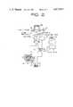
- FIG. 1is a cross-sectional view showing an embodiment of an apparatus in accordance with the present invention.
- FIG. 2is a block diagram of a control circuit for the apparatus.
- numeral 1designates a crankshaft of an internal combustion engine mounted on a car (not shown).
- the crankshaft 1is connected with an input shaft 4 of a transmission 3 through a well known mechanical clutch 2, which in turn is connected with a front differential device 5 disposed between the transmission 3 and the clutch 2.
- the transmission 3has an output shaft 6 disposed parallel to the input shaft 4.
- the input shaft 4is formed integrally with a 1st-speed gear 7 and a 2nd-speed gear 8 and has a 3rd-speed gear 9 and a 4th-speed gear 10 rotatably mounted thereon.
- the output shaft 6has gears 11 and 12 engaged with gears 7 and 8 respectively, gears 13 and 14 engaged with gears 9 and 10 respectively, and a synchromesh mechanism 15 arranged between the gears 9 and 10 and a synchromesh mechanism 16 between the gears 11 and 12.
- the synchromesh mechanism 16is operated to engage the gear 11 with the output shaft 6 by a shift lever (not shown), and thus the power from the input shaft 4 is transmitted to the output shaft 6 by means of the 11 at the 4th-speed transmission.
- three other steps of forward drive transmissionsare achieved.
- Rearward drive transmissionis achieved by engagement of a gear 17 provided on the shaft 4 with a gear 18 formed on the sleeve side of the synchromesh mechanism 16 through an idling gear (not shown).
- a drive pinion 5a for the front differential device 5is formed integrally on the front end of the output shaft 6 and is engaged with a ring gear 5b.
- the rear end of the output shaft 6is connected to a shaft 21 disposed in alignment with the input shaft 4 by means of a pair of gears 19, 20 which are engaged with each other.
- This shaft 21is to be connected to a rear differential device 25 through an electromagnetic clutch 22a, shaft 23 and a propeller shaft 24 and so on.
- the electromagnetic clutchcomprises a drive member 27 secured to the shaft 21 by means of a drive plate 26, a driven member 28 secured mounted on the shaft 23, a magnetizing coil 29 provided in the drive member 27, clutch brushes 30, slip rings 31 and lines 32 connected to the magnetizing coil 29 to generate magnetic flux.
- the electromagnetic clutch 22is engaged by magnetic powder aggregated in a small gap between the drive member 27 and the driven member 28 by the magnetic flux.
- a steering angle sensor 35is provided on a steering gear box 34 of a steering device 33 to detect the steering angle.
- the steering angle sensor 35is so arranged that when the steering angle exceeds a predetermined angle, an output signal is generated and which increases with an increase of the angle.
- a pair of rotation speed sensors 38a, 38bare provided respectively on wheel shafts 37a and 37b which are connected with respective front wheels 36a and 36b as main wheels for driving the vehicle.
- a slip detecting circuit 39comprising a comparator is applied with output signals from these rotation speed sensors 38a and 38b and adapted to detect the occurrence of slippage by the difference between these output signals.
- a vehicle speed sensor 40 and a manually operated select switch 41 for selecting the two-wheel or four-wheel drivesare also provided.
- the sensors 35, 40, the slip detecting circuit 39 and the select switch 41are connected to a control circuit 42 for controlling the clutch current passing through the magnetizing coil 29.
- the control circuit 42comprises gate circuits and a current control circuit. The control circuit is designated such that when the select switch 41 is operated to select the two-wheel drive, the clutch current is cut off, and when the four-wheel drive is selected, the clutch current is applied to the magnetizing coil 29 in such a manner as to increase stepwise to mitigate the shock caused by changing of the transmission.
- the clutch currentdecreased with an increase of the steering angle and cuts off at a predetermined steering angle.
- the control circuit 42is adapted to apply the clutch current to the magnetizing coil 29 for engaging the clutch 22, when slipping of one of front wheels 36a, 36b is detected by the output of the slip detecting circuit 39.
- the electromagnetic clutch 22is disengaged.
- the transmission of power of the engine to the rear wheelsis cut off, so that the vehicle is driven by the front wheels.
- the control circuit 42is actuated by the signal from the slip detecting circuit 39 to increase the clutch current rapidly to engage the electromagnetic clutch 22.
- the power of the transmission 3is transmitted also to the rear wheels through the propeller shaft 24 and the rear differential device 25, achieving four-wheel drive to thereby recover the steady driving condition.
- the slip detecting circuit 39sends no more signals and the transmission turns back to the two-wheel drive condition.
- the electromagnetic clutch 22is engaged, resulting in the four-wheel drive.
- the steering angle sensor 35produces an output signal for controlling the clutch current.
- the clutch currentdecreases as the steering angle increases.
- less poweris transmitted to the rear wheels to thereby drive them at lower speed.
- the vehiclecan be smoothly driven at a sharp turn.
- no longeris a signal sent from the steering angle sensor 35, so that the clutch current flows through the magnetizing coil 29 to engage the electromagnetic clutch 22 again.
- the power from the transmission 3is transmitted to the rear wheels to achieve the four-wheel drive.
Landscapes
- Engineering & Computer Science (AREA)
- Chemical & Material Sciences (AREA)
- Combustion & Propulsion (AREA)
- Transportation (AREA)
- Mechanical Engineering (AREA)
- Arrangement And Driving Of Transmission Devices (AREA)
- Arrangement And Mounting Of Devices That Control Transmission Of Motive Force (AREA)
Abstract
Description
The present invention relates to a system for a four-wheel drive vehicle for automatically changing the transmission from the two-wheel drive condition to the four-wheel drive condition or vice versa in accordance with the driving conditions. The present invention relates more particularly to a changing apparatus for the transmission having two-wheel drive and four-wheel drive transmitting devices, which employs an electromagnetic clutch in order to improve driving during a sharp turn.
In conventional four-wheel drive vehicles, a transmission device is adapted to drive either two wheels or four wheels by means of a dog clutch which is manually operated by a select lever.
Generally when a vehicle makes a turn, the rotating speeds of the front wheels and the rear wheels are different because of the difference between the turning radii of the front wheels and the rear wheels. However, usually a central differential gear for absorbing the difference is omitted to simplify construction. Accordingly, when a vehicle turns at a small radius, the rear wheels act to drive the vehicle at a speed higher than the speed driven by the front wheels because the rear wheels travel on a circle of a radius smaller than that of the front wheels. This will cause a so-called tight-corner or tight-turn braking phenomenon whereby the vehicle cannot be smoothly driven during a sharp turn.
It is an object of the present invention to provide an apparatus for controlling two-wheel and four-wheel drives during sharp turning which does not have the above disadvantages.
Therefore, the present invention provides an apparatus for controlling two-wheel and four-wheel drives which comprises an electromagnetic clutch enabling a change of the engaging state of a transmission with either of two wheels or four wheels by means of a signal, a steering angle sensor, and a control circuit. The control circuit cuts off the clutch current to the electromagnetic clutch changing to the two wheel drive when an output signal is applied thereto during driving at a sharp turn so that the tight-corner braking phenomenon is prevented.
The present invention will be explained more in detail with reference to the accompanying drawings.
FIG. 1 is a cross-sectional view showing an embodiment of an apparatus in accordance with the present invention; and
FIG. 2 is a block diagram of a control circuit for the apparatus.
In FIG. 1,numeral 1 designates a crankshaft of an internal combustion engine mounted on a car (not shown). Thecrankshaft 1 is connected with an input shaft 4 of a transmission 3 through a well known mechanical clutch 2, which in turn is connected with a frontdifferential device 5 disposed between the transmission 3 and the clutch 2. The transmission 3 has an output shaft 6 disposed parallel to the input shaft 4. The input shaft 4 is formed integrally with a 1st-speed gear 7 and a 2nd-speed gear 8 and has a 3rd-speed gear 9 and a 4th-speed gear 10 rotatably mounted thereon. The output shaft 6 has gears 11 and 12 engaged with gears 7 and 8 respectively,gears differential device 5 is formed integrally on the front end of the output shaft 6 and is engaged with a ring gear 5b.
The rear end of the output shaft 6 is connected to a shaft 21 disposed in alignment with the input shaft 4 by means of a pair of gears 19, 20 which are engaged with each other. This shaft 21 is to be connected to a rear differential device 25 through an electromagnetic clutch 22a, shaft 23 and apropeller shaft 24 and so on. The electromagnetic clutch comprises a drive member 27 secured to the shaft 21 by means of adrive plate 26, a drivenmember 28 secured mounted on the shaft 23, a magnetizing coil 29 provided in the drive member 27,clutch brushes 30,slip rings 31 andlines 32 connected to the magnetizing coil 29 to generate magnetic flux. Theelectromagnetic clutch 22 is engaged by magnetic powder aggregated in a small gap between the drive member 27 and the drivenmember 28 by the magnetic flux.
As clutch current supplied to the magnetizing coil 29 increases gradually, the clutch torque of the clutch increases.
An embodiment of the electromagnetic clutch control system according to the present invention will be explained hereinafter with reference to FIG. 2. Asteering angle sensor 35 is provided on asteering gear box 34 of asteering device 33 to detect the steering angle. Thesteering angle sensor 35 is so arranged that when the steering angle exceeds a predetermined angle, an output signal is generated and which increases with an increase of the angle. A pair ofrotation speed sensors wheel shafts front wheels slip detecting circuit 39 comprising a comparator is applied with output signals from theserotation speed sensors sensors 35, 40, theslip detecting circuit 39 and the select switch 41 are connected to acontrol circuit 42 for controlling the clutch current passing through the magnetizing coil 29. Thecontrol circuit 42 comprises gate circuits and a current control circuit. The control circuit is designated such that when the select switch 41 is operated to select the two-wheel drive, the clutch current is cut off, and when the four-wheel drive is selected, the clutch current is applied to the magnetizing coil 29 in such a manner as to increase stepwise to mitigate the shock caused by changing of the transmission.
When an output signal of the vehicle speed sensor 40 and the signal of the four-wheel drive from the select switch 41 are applied to thecontrol circuit 42 and further the signal from thesteering angle sensor 35 is applied thereto during the turning of the vehicle, the clutch current decreased with an increase of the steering angle and cuts off at a predetermined steering angle. Further, thecontrol circuit 42 is adapted to apply the clutch current to the magnetizing coil 29 for engaging theclutch 22, when slipping of one offront wheels slip detecting circuit 39.
In operation, when the select switch 41 is operated for two-wheel driving to cut off the clutch current, theelectromagnetic clutch 22 is disengaged. Thus, the transmission of power of the engine to the rear wheels is cut off, so that the vehicle is driven by the front wheels. If, in the two-wheel driving condition, one of the front wheels slips, thecontrol circuit 42 is actuated by the signal from theslip detecting circuit 39 to increase the clutch current rapidly to engage theelectromagnetic clutch 22. Thus, the power of the transmission 3 is transmitted also to the rear wheels through thepropeller shaft 24 and the rear differential device 25, achieving four-wheel drive to thereby recover the steady driving condition. When the vehicle is relieved from slipping, theslip detecting circuit 39 sends no more signals and the transmission turns back to the two-wheel drive condition. If the select switch 41 is turned to the four-wheel drive position, theelectromagnetic clutch 22 is engaged, resulting in the four-wheel drive. When the vehicle turns a sharp corner, thesteering angle sensor 35 produces an output signal for controlling the clutch current. Thus, the clutch current decreases as the steering angle increases. Thus, less power is transmitted to the rear wheels to thereby drive them at lower speed. Thus, the vehicle can be smoothly driven at a sharp turn. After turning, no longer is a signal sent from thesteering angle sensor 35, so that the clutch current flows through the magnetizing coil 29 to engage theelectromagnetic clutch 22 again. Thus, the power from the transmission 3 is transmitted to the rear wheels to achieve the four-wheel drive.
Since driving with two wheels or four wheels is automatically selected in accordance with the driving condition, sensitive operability is obtainable. During turning of the vehicle when it is being driven by four wheels, a part or all of the driving power to the rear wheels is cut off by the electro-magnetic clutch. That is to say, the driving power escapes through theelectromagnetic clutch 22, that causes the speed difference between the front wheels and rear wheels to prevent the tight-corner braking phenomenon and other damages accompanied therewith. Although the illustrated system is provided with the vehicle speed sensor 40, it will be understood that the sensor is not always necessary.
Claims (13)
1. A system for controlling driving with two wheels or four wheels, respectively in a vehicle powered by an internal combustion engine comprising
transmission means for transmitting power from said engine to two main wheels of said vehicle,
an electromagnetic clutch means having a magnetizing coil for selectively transmitting said power to two auxiliary wheels of the vehicle,
a select switch means for energizing said magnetizing coil with clutch current for engaging said electromagnetic clutch means,
means for detecting steering angle for producing an output signal when the steering angle exceeds a predetermined value, and
control circuit means for cutting off said clutch current when said output signal of said steering angle detecting means is applied thereto, so as to disengage said electromagnetic clutch means.
2. The system according to claim 1 further comprising
a slip detecting circuit means for detecting slipping of one of said two main wheels and for producing an output signal when slipping occurs, and
said control circuit means for supplying the clutch current to said electromagnetic clutch means in dependency on said output signal of said slip detecting circuit means.
3. The system according to claim 1, wherein
said select switch means is a manually operated switch.
4. The system according to claim 1, wherein
said select switch means is for supplying the clutch current to said electromagnetic clutch means stepwise when driving with four wheels is selected.
5. The system according to claim 1, wherein
said control circuit means for reapplying the clutch current to said electromagnetic clutch means stepwise so as to reengage said electromagnetic clutch means when said steering angle falls back to said predetermined value.
6. The system according to claim 1, further comprising
a vehicle speed sensor means for detecting vehicle speed,
said control circuit means via said steering angle detecting means for decreasing the clutch current to said electromagnetic clutch means dependent on the steering angle when said vehicle speed sensor means detects vehicle speed and said select switch means is in a condition for energizing said magnetizing coil with the clutch current for engaging said electromagnetic clutch means so as to drive with the power transmission to the four wheels.
7. A system for controlling driving with two wheels or four wheels, respectively in a vehicle powered by an internal combustion engine comprising
transmission means for transmitting power from said engine to two main wheels of said vehicle,
an electromagnetic clutch means having a magnetizing coil for selectively transmitting said power to two auxiliary wheels of the vehicle,
a select switch means for energizing said magnetizing coil with clutch current for engaging said electromagnetic clutch means,
means for detecting steering angle for producing an output signal with a level which increases with an increase of the steering angle, and
control circuit means for controlling the clutch current applied to said magnetizing coil of said electromagnetic clutch means by decreasing said clutch current with an increase in the level of said output signal when said output signal of said steering angle detecting means is applied to said control circuit means when driving with the power transmission to the four wheels.
8. The system according to claim 7 further wherein
said control circuit means for cutting off the clutch current so as to disengage said electromagnetic clutch means when said output signal level of said steering angle detecting means exceeds a predetermined value.
9. The system according to claim 8, wherein
said control circuit means for reapplying the clutch current to said electromagnetic clutch means stepwise so as to reengage said electromagnetic clutch means when said output signal level of said steering angle detecting means falls back to said predetermined value.
10. The system according to claim 7 further comprising
a slip detecting circuit means for detecting slipping of one of said two main wheels and for producing an output signal when slipping occurs, and
said control circuit means for supplying the clutch current to said electromagnetic clutch means in dependency on said output signal of said slip detecting circuit means.
11. The system according to claim 7, wherein
said select switch means is a manually operated switch.
12. The system according to claim 11, wherein
said select switch means is for supplying the clutch current to said electromagnetic clutch means stepwise when driving with four-wheels is selected.
13. The system according to claim 7, further comprising
a vehicle speed sensor means for detecting vehicle speed,
said control circuit means via said steering angle detecting means for decreasing the clutch current to said electromagnetic clutch means dependent on the steering angle when said vehicle speed sensor means detects vehicle speed and said select switch means is in a condition for energizing said magnetizing coil with the clutch current for engaging said electromagnetic clutch means so as to drive with the power transmission to the four wheels.
Applications Claiming Priority (2)
| Application Number | Priority Date | Filing Date | Title |
|---|---|---|---|
| JP8833180AJPS5715019A (en) | 1980-06-27 | 1980-06-27 | Changeover device for 2, 4 wheel drive in 4-wheel drive vehicle |
| JP55-88331 | 1980-06-27 |
Publications (1)
| Publication Number | Publication Date |
|---|---|
| US4417641Atrue US4417641A (en) | 1983-11-29 |
Family
ID=13939886
Family Applications (1)
| Application Number | Title | Priority Date | Filing Date |
|---|---|---|---|
| US06/276,326Expired - Fee RelatedUS4417641A (en) | 1980-06-27 | 1981-06-22 | System for controlling two-wheel and four-wheel drives |
Country Status (5)
| Country | Link |
|---|---|
| US (1) | US4417641A (en) |
| EP (1) | EP0043237B1 (en) |
| JP (1) | JPS5715019A (en) |
| AU (1) | AU530547B2 (en) |
| DE (1) | DE3168133D1 (en) |
Cited By (59)
| Publication number | Priority date | Publication date | Assignee | Title |
|---|---|---|---|---|
| US4466502A (en)* | 1981-09-29 | 1984-08-21 | Fuji Jukogyo Kabushiki Kaisha | System for controlling transmission torque of a four-wheel drive vehicle |
| US4484653A (en)* | 1981-06-12 | 1984-11-27 | Hitachi, Ltd. | Automatic driving wheel change-over apparatus |
| US4511014A (en)* | 1981-07-07 | 1985-04-16 | Fuji Jukogyo Kabushiki Kaisha | System for controlling a power transmission of a four-wheel drive vehicle |
| DE3427725A1 (en)* | 1984-02-14 | 1985-08-22 | Volkswagenwerk Ag, 3180 Wolfsburg | Arrangement for controlling the power transmission of a four-wheel drive motor vehicle with transfer box |
| US4556134A (en)* | 1982-01-29 | 1985-12-03 | Fuji Jukogyo Kabushiki Kaisha | Power transmission system for a four-wheel drive vehicle |
| US4566554A (en)* | 1983-05-09 | 1986-01-28 | Nissan Motor Co., Ltd. | Four wheel drive system with center differential unlock control responsive to steering angle |
| US4576061A (en)* | 1982-12-16 | 1986-03-18 | Fuji Jukogyo Kabushiki Kaisha | System for controlling the transmission of a four-wheel drive vehicle |
| US4582159A (en)* | 1983-04-01 | 1986-04-15 | Nissan Motor Company, Limited | Part-time four-wheel drive system with braking force responsive control |
| US4609064A (en)* | 1983-05-24 | 1986-09-02 | Nissan Motor Co., Ltd. | Part-time four-wheel drive system with steering angle responsive control |
| US4613008A (en)* | 1984-12-12 | 1986-09-23 | Nissan Motor Co., Ltd. | 2WD-4WD change-over control system responsive to rainfall and acceleration |
| US4628770A (en)* | 1983-07-30 | 1986-12-16 | Fuji Jukogyo Kabushiki Kaisha | Overdrive system for a four-wheel drive vehicle |
| US4630704A (en)* | 1983-09-20 | 1986-12-23 | Fuji Jukogyo Kabushiki Kaisha | System for controlling a power transmission of a four-wheel drive vehicle |
| US4664216A (en)* | 1984-05-10 | 1987-05-12 | Fuji Jukogyo Kabushiki Kaisha | Four-wheel drive vehicle |
| US4669569A (en)* | 1983-04-04 | 1987-06-02 | Nissan Motor Co., Ltd. | Four-wheel drive system with differential control response to tire-to-tire friction |
| US4678056A (en)* | 1984-10-09 | 1987-07-07 | Nissan Motor Co., Ltd. | Part time four wheel drive vehicle with road surface condition sensor |
| US4705134A (en)* | 1985-04-30 | 1987-11-10 | Fuji Jukogyo Kabushiki Kaisha | System for controlling a transfer clutch of a four-wheel drive vehicle |
| US4711317A (en)* | 1985-04-30 | 1987-12-08 | Fuji Jukogyo Kabushiki Kaisha | System for controlling a transfer clutch of a four-wheel drive vehicle |
| US4714127A (en)* | 1985-08-06 | 1987-12-22 | Alfa Romeo Auto S.P.A. | Control apparatus for a vehicle with disengageable four-wheel drive |
| US4718515A (en)* | 1985-08-06 | 1988-01-12 | Alfa Romeo Auto S.P.A. | Control device for a vehicle with disengageable four-wheel drive |
| US4718303A (en)* | 1986-10-06 | 1988-01-12 | Borg-Warner Automotive, Inc. | Four wheel drive transfer case with clutch mechanism |
| US4745826A (en)* | 1985-01-19 | 1988-05-24 | Aisin-Warner Limited | Shift condition detector for an automatic vehicle transmission |
| US4751857A (en)* | 1985-06-29 | 1988-06-21 | Fuji Jukogyo Kabushiki Kaisha | System for controlling the pressure of oil in a system for an infinitely variable transmission |
| US4804059A (en)* | 1986-09-30 | 1989-02-14 | Fuji Jukogyo Kabushiki Kaisha | System for controlling a transfer clutch of a four-wheel drive vehicle |
| US4821606A (en)* | 1986-08-13 | 1989-04-18 | Daimler-Benz Aktiengesellschaft | Arrangement for automatically shifting vehicle aggregates of a motor vehicle |
| US4830136A (en)* | 1986-07-01 | 1989-05-16 | Steyr-Daimler-Puch Aktiengesellschaft | Four-wheel drive motor vehicle |
| US4831896A (en)* | 1986-09-10 | 1989-05-23 | Fuji Jukogyo Kabushiki Kaisha | Line pressure control system for an automatic transmission |
| US4840246A (en)* | 1983-09-19 | 1989-06-20 | Fuji Jukogyo Kabushiki Kaisha | Power transmission control system for a four-wheel drive vehicle |
| US4860612A (en)* | 1985-04-01 | 1989-08-29 | Dana Corporation | Vehicle torque transfer case for a four wheel drive system |
| US4895236A (en)* | 1987-02-02 | 1990-01-23 | Aisin-Warner Kabushiki Kaisha | Actuator for the frictional engaging device |
| US4896738A (en)* | 1986-06-20 | 1990-01-30 | Fuji Jukogyo Kabushiki Kaisha | Power transmitting system for a four-wheel drive vehicle |
| US4937750A (en)* | 1987-12-23 | 1990-06-26 | Dana Corporation | Electronic control for vehicle four wheel drive system |
| AT392038B (en)* | 1984-12-12 | 1991-01-10 | Steyr Daimler Puch Ag | DRIVE ARRANGEMENT FOR TWO DRIVEN MOTOR VEHICLE AXLES |
| US5075854A (en)* | 1987-10-09 | 1991-12-24 | Nissan Motor Co., Ltd. | Differential limiting force control system responsive to vehicle speed and steering angle |
| US5107972A (en)* | 1991-09-13 | 1992-04-28 | Borg-Warner Automotive, Inc. | Electromagnetic clutch assembly for four wheel drive systems |
| US5215160A (en)* | 1991-07-02 | 1993-06-01 | New Venture Gear, Inc. | Part-time on-demand transfer case and method |
| US5323871A (en)* | 1993-03-10 | 1994-06-28 | New Venture Gear, Inc. | Rotary actuation mechanism for torque modulated transfer case |
| US5330030A (en)* | 1993-03-09 | 1994-07-19 | New Venture Gear, Inc. | Two-speed transfer case with electronic torque modulation |
| GB2274320A (en)* | 1993-01-19 | 1994-07-20 | Sauer Inc | An electromagnetic clutch driven steerable drive axle for a four wheel drive vehicle |
| US5332060A (en)* | 1993-03-10 | 1994-07-26 | New Venture Gear, Inc. | Linear actuation mechanism for electronically-controlled torque modulated transfer case |
| US5363938A (en)* | 1993-03-09 | 1994-11-15 | New Venture Gear, Inc. | Power transfer system for a four-wheel drive vehicle |
| US5400866A (en)* | 1993-03-10 | 1995-03-28 | New Venture Gear, Inc. | Torque modulated transfer case |
| US5407024A (en)* | 1992-06-24 | 1995-04-18 | Borg-Warner Automotive, Inc. | On demand vehicle drive system |
| US5411110A (en)* | 1993-03-09 | 1995-05-02 | New Venture Gear, Inc. | Power transfer system for a four-wheel drive vehicle |
| US5582263A (en)* | 1993-03-10 | 1996-12-10 | New Venture Gear, Inc. | Full-time four wheel drive transfer case |
| US5704444A (en)* | 1995-12-11 | 1998-01-06 | Borg-Warner Automotive, Inc. | Adaptive vehicle drive system for extreme operating conditioning |
| US6000488A (en)* | 1992-06-24 | 1999-12-14 | Borg-Warner Automotive, Inc. | Motor vehicle transfer case |
| US6071207A (en)* | 1993-03-10 | 2000-06-06 | New Venture Gear, Inc. | Full-time transfer case with mode shift arrangement |
| US6466855B2 (en)* | 2000-07-14 | 2002-10-15 | Toyota Jidosha Kabushiki Kaisha | Vehicle speed estimating apparatus and method and vehicular control apparatus and method |
| US6645108B1 (en) | 2002-05-16 | 2003-11-11 | The Timken Company | Active torque bias system and controls |
| US20040054459A1 (en)* | 2002-09-13 | 2004-03-18 | Brooks Cary Walter | Drive torque transfer scheme |
| US6712728B2 (en) | 2002-01-29 | 2004-03-30 | The Timken Company | Transfer case with enhanced torque bias capability |
| US6712730B2 (en) | 2001-12-06 | 2004-03-30 | The Timken Company | Active torque bias coupling |
| US6755762B2 (en) | 2002-03-25 | 2004-06-29 | The Timken Company | Axle center with active torque bias control |
| US20040187572A1 (en)* | 2003-01-08 | 2004-09-30 | Honda Motor Co., Ltd. | Vehicle speed display apparatus |
| US20050209763A1 (en)* | 2004-03-18 | 2005-09-22 | Ford Global Technologies, Llc | Method and apparatus for controlling brake-steer in an automotive vehicle in reverse |
| US7276014B2 (en) | 2004-11-05 | 2007-10-02 | Ntn Corporation | Vehicle stability control system for enhanced transfer case compatibility |
| US20080083578A1 (en)* | 2006-10-04 | 2008-04-10 | Andrew Wayne Kelly | Vehicular Drive System With FWD-Only Mode And Associated Method |
| US20090045001A1 (en)* | 2007-08-13 | 2009-02-19 | Magna Powertrain Ag & Co Kg | Method for calibrating of an actuator of an all-wheel drive clutch |
| US10166865B2 (en) | 2010-10-18 | 2019-01-01 | Ford Global Technologies, Llc | Automatic control of driveline states |
Families Citing this family (29)
| Publication number | Priority date | Publication date | Assignee | Title |
|---|---|---|---|---|
| JPS5820521A (en)* | 1981-07-25 | 1983-02-07 | Fuji Heavy Ind Ltd | Avoiding mechanism of tight corner braking in 4-wheel driven car |
| JPS59176121A (en)* | 1983-03-24 | 1984-10-05 | Kubota Ltd | Front wheel drive control device for four-wheel drive vehicles |
| JPS60176827A (en)* | 1984-02-23 | 1985-09-10 | Fuji Heavy Ind Ltd | Differential gear lock device in four wheels drive vehicle |
| DE3429986A1 (en) | 1984-08-16 | 1986-02-27 | Fuji Jukogyo K.K., Tokio/Tokyo | Power transmission arrangement for a four-wheel-drive vehicle |
| JPS6141039U (en)* | 1984-08-22 | 1986-03-15 | 三菱自動車工業株式会社 | four wheel drive vehicle |
| DE3437436C2 (en)* | 1984-10-12 | 1986-08-21 | Dr.Ing.H.C. F. Porsche Ag, 7000 Stuttgart | Arrangement for controlling the power transmission of a four-wheel drive vehicle |
| DE3437435C2 (en)* | 1984-10-12 | 1986-08-21 | Dr.Ing.H.C. F. Porsche Ag, 7000 Stuttgart | Arrangement for controlling the power transmission of a four-wheel drive vehicle |
| JPS61122032A (en)* | 1984-11-17 | 1986-06-10 | Nissan Motor Co Ltd | Driving force distribution device for 4-wheel drive vehicles |
| JPS61169326A (en)* | 1985-01-21 | 1986-07-31 | Nissan Motor Co Ltd | Driving force distribution controller for 4 wheel drive car |
| DE3505455A1 (en)* | 1985-02-16 | 1986-08-28 | Daimler-Benz Ag, 7000 Stuttgart | DEVICE FOR AUTOMATICALLY SWITCHING ON AND OFF OF DRIVE ELEMENTS OF A MOTOR VEHICLE |
| JPS6231528A (en)* | 1985-08-05 | 1987-02-10 | Fuji Heavy Ind Ltd | Full-time type four wheel drive vehicle |
| DE3668586D1 (en)* | 1985-08-30 | 1990-03-08 | Mazda Motor | TORQUE CONTROL SYSTEM FOR VEHICLES. |
| US4773500A (en)* | 1985-09-13 | 1988-09-27 | Nissan Motor Co., Ltd. | Driving torque distribution control system for 4WD vehicle |
| US4702341A (en)* | 1985-12-13 | 1987-10-27 | Toyota Jidosha Kabushiki Kaisha | Four wheel drive vehicle slippage control device and method limiting center differential action according to input torque supplied thereto |
| DE3544525A1 (en)* | 1985-12-17 | 1987-06-19 | Fendt & Co Xaver | Steering axle for tractors usable for agriculture, in particular for narrow-track tractors |
| EP0231665B1 (en)* | 1985-12-27 | 1991-07-24 | Aisin-Warner Kabushiki Kaisha | Control apparatus for four-wheel drive vehicle with center differential mechanism |
| US4744437A (en)* | 1986-02-27 | 1988-05-17 | Fuji Jukogyo Kabushiki Kaisha | Power transmitting system for a four-wheel drive vehicle |
| DE3766386D1 (en)* | 1986-03-11 | 1991-01-10 | Porsche Ag | ARRANGEMENT FOR CONTROLLING THE POWER TRANSMISSION OF A FOUR WHEEL-DRIVEN VEHICLE. |
| JPS62238115A (en)* | 1986-04-07 | 1987-10-19 | Fuji Heavy Ind Ltd | Driving shaft selection device for four-wheel drive vehicle |
| JP2517911B2 (en)* | 1986-06-10 | 1996-07-24 | トヨタ自動車株式会社 | Control method of four-wheel drive device |
| JPH0818502B2 (en)* | 1986-06-30 | 1996-02-28 | アイシン・エィ・ダブリュ株式会社 | 4-wheel drive vehicle with front and rear wheel engagement mechanism |
| US4792010A (en)* | 1986-07-11 | 1988-12-20 | 501 Kubota, Ltd. | Four wheel drive vehicle |
| JP2577902B2 (en)* | 1987-02-27 | 1997-02-05 | 富士重工業株式会社 | Fail-safe device for four-wheel drive vehicle |
| JP2548229B2 (en)* | 1987-10-09 | 1996-10-30 | 日産自動車株式会社 | Drive force distribution controller for four-wheel drive vehicle |
| JPH0764221B2 (en)* | 1987-10-20 | 1995-07-12 | 日産自動車株式会社 | Differential limiting force controller |
| JPH01107635U (en)* | 1988-01-13 | 1989-07-20 | ||
| DE3904493A1 (en)* | 1989-02-15 | 1990-08-16 | Deere & Co | DRIVE DEVICE FOR AT LEAST TWO COUPLES |
| JP2913965B2 (en)* | 1991-12-05 | 1999-06-28 | 日産自動車株式会社 | Front / rear driving force distribution control device for four-wheel drive vehicle |
| US8108109B2 (en)* | 2007-06-01 | 2012-01-31 | Clark Equipment Company | Drive control system for a vehicle and method |
Citations (5)
| Publication number | Priority date | Publication date | Assignee | Title |
|---|---|---|---|---|
| DE2212328A1 (en)* | 1972-03-15 | 1973-09-27 | Teldix Gmbh | ARRANGEMENT FOR COMPENSATION OF YEAR MOMENTS |
| US3763947A (en)* | 1971-09-21 | 1973-10-09 | Allis Chalmers | Tractor four wheel drive |
| JPS53111937A (en)* | 1977-03-08 | 1978-09-29 | Iseki & Co Ltd | Front wheel drive clutch device for four-wheel drive power agricultural vehicle |
| JPS55152624A (en)* | 1979-05-16 | 1980-11-28 | Kubota Ltd | Work vehicle |
| US4298085A (en)* | 1978-11-24 | 1981-11-03 | Aisin-Warner K.K. | Automatic four-wheel drive transfer case |
Family Cites Families (3)
| Publication number | Priority date | Publication date | Assignee | Title |
|---|---|---|---|---|
| AT8388B (en)* | 1900-09-29 | 1902-07-25 | Transformateurs Automobiles Ri | Device for coupling the drive wheels with the engine in motor vehicles with steering wheel drive. |
| US4186816A (en)* | 1978-05-30 | 1980-02-05 | Deere & Company | Supplementary hydrostatic drive electronic control |
| JPS55148622A (en)* | 1979-05-09 | 1980-11-19 | Kubota Ltd | Working vehicle |
- 1980
- 1980-06-27JPJP8833180Apatent/JPS5715019A/enactiveGranted
- 1981
- 1981-06-22USUS06/276,326patent/US4417641A/ennot_activeExpired - Fee Related
- 1981-06-24EPEP81302855Apatent/EP0043237B1/ennot_activeExpired
- 1981-06-24DEDE8181302855Tpatent/DE3168133D1/ennot_activeExpired
- 1981-06-26AUAU72189/81Apatent/AU530547B2/ennot_activeCeased
Patent Citations (5)
| Publication number | Priority date | Publication date | Assignee | Title |
|---|---|---|---|---|
| US3763947A (en)* | 1971-09-21 | 1973-10-09 | Allis Chalmers | Tractor four wheel drive |
| DE2212328A1 (en)* | 1972-03-15 | 1973-09-27 | Teldix Gmbh | ARRANGEMENT FOR COMPENSATION OF YEAR MOMENTS |
| JPS53111937A (en)* | 1977-03-08 | 1978-09-29 | Iseki & Co Ltd | Front wheel drive clutch device for four-wheel drive power agricultural vehicle |
| US4298085A (en)* | 1978-11-24 | 1981-11-03 | Aisin-Warner K.K. | Automatic four-wheel drive transfer case |
| JPS55152624A (en)* | 1979-05-16 | 1980-11-28 | Kubota Ltd | Work vehicle |
Cited By (74)
| Publication number | Priority date | Publication date | Assignee | Title |
|---|---|---|---|---|
| US4484653A (en)* | 1981-06-12 | 1984-11-27 | Hitachi, Ltd. | Automatic driving wheel change-over apparatus |
| US4511014A (en)* | 1981-07-07 | 1985-04-16 | Fuji Jukogyo Kabushiki Kaisha | System for controlling a power transmission of a four-wheel drive vehicle |
| US4466502A (en)* | 1981-09-29 | 1984-08-21 | Fuji Jukogyo Kabushiki Kaisha | System for controlling transmission torque of a four-wheel drive vehicle |
| US4556134A (en)* | 1982-01-29 | 1985-12-03 | Fuji Jukogyo Kabushiki Kaisha | Power transmission system for a four-wheel drive vehicle |
| US4576061A (en)* | 1982-12-16 | 1986-03-18 | Fuji Jukogyo Kabushiki Kaisha | System for controlling the transmission of a four-wheel drive vehicle |
| US4582159A (en)* | 1983-04-01 | 1986-04-15 | Nissan Motor Company, Limited | Part-time four-wheel drive system with braking force responsive control |
| US4669569A (en)* | 1983-04-04 | 1987-06-02 | Nissan Motor Co., Ltd. | Four-wheel drive system with differential control response to tire-to-tire friction |
| US4566554A (en)* | 1983-05-09 | 1986-01-28 | Nissan Motor Co., Ltd. | Four wheel drive system with center differential unlock control responsive to steering angle |
| US4609064A (en)* | 1983-05-24 | 1986-09-02 | Nissan Motor Co., Ltd. | Part-time four-wheel drive system with steering angle responsive control |
| US4628770A (en)* | 1983-07-30 | 1986-12-16 | Fuji Jukogyo Kabushiki Kaisha | Overdrive system for a four-wheel drive vehicle |
| US4840246A (en)* | 1983-09-19 | 1989-06-20 | Fuji Jukogyo Kabushiki Kaisha | Power transmission control system for a four-wheel drive vehicle |
| US4630704A (en)* | 1983-09-20 | 1986-12-23 | Fuji Jukogyo Kabushiki Kaisha | System for controlling a power transmission of a four-wheel drive vehicle |
| DE3427725A1 (en)* | 1984-02-14 | 1985-08-22 | Volkswagenwerk Ag, 3180 Wolfsburg | Arrangement for controlling the power transmission of a four-wheel drive motor vehicle with transfer box |
| US4664216A (en)* | 1984-05-10 | 1987-05-12 | Fuji Jukogyo Kabushiki Kaisha | Four-wheel drive vehicle |
| US4678056A (en)* | 1984-10-09 | 1987-07-07 | Nissan Motor Co., Ltd. | Part time four wheel drive vehicle with road surface condition sensor |
| US4613008A (en)* | 1984-12-12 | 1986-09-23 | Nissan Motor Co., Ltd. | 2WD-4WD change-over control system responsive to rainfall and acceleration |
| AT392038B (en)* | 1984-12-12 | 1991-01-10 | Steyr Daimler Puch Ag | DRIVE ARRANGEMENT FOR TWO DRIVEN MOTOR VEHICLE AXLES |
| US4745826A (en)* | 1985-01-19 | 1988-05-24 | Aisin-Warner Limited | Shift condition detector for an automatic vehicle transmission |
| US4860612A (en)* | 1985-04-01 | 1989-08-29 | Dana Corporation | Vehicle torque transfer case for a four wheel drive system |
| US4711317A (en)* | 1985-04-30 | 1987-12-08 | Fuji Jukogyo Kabushiki Kaisha | System for controlling a transfer clutch of a four-wheel drive vehicle |
| US4705134A (en)* | 1985-04-30 | 1987-11-10 | Fuji Jukogyo Kabushiki Kaisha | System for controlling a transfer clutch of a four-wheel drive vehicle |
| US4751857A (en)* | 1985-06-29 | 1988-06-21 | Fuji Jukogyo Kabushiki Kaisha | System for controlling the pressure of oil in a system for an infinitely variable transmission |
| US4714127A (en)* | 1985-08-06 | 1987-12-22 | Alfa Romeo Auto S.P.A. | Control apparatus for a vehicle with disengageable four-wheel drive |
| US4718515A (en)* | 1985-08-06 | 1988-01-12 | Alfa Romeo Auto S.P.A. | Control device for a vehicle with disengageable four-wheel drive |
| US4896738A (en)* | 1986-06-20 | 1990-01-30 | Fuji Jukogyo Kabushiki Kaisha | Power transmitting system for a four-wheel drive vehicle |
| US4830136A (en)* | 1986-07-01 | 1989-05-16 | Steyr-Daimler-Puch Aktiengesellschaft | Four-wheel drive motor vehicle |
| US4821606A (en)* | 1986-08-13 | 1989-04-18 | Daimler-Benz Aktiengesellschaft | Arrangement for automatically shifting vehicle aggregates of a motor vehicle |
| US4831896A (en)* | 1986-09-10 | 1989-05-23 | Fuji Jukogyo Kabushiki Kaisha | Line pressure control system for an automatic transmission |
| US4804059A (en)* | 1986-09-30 | 1989-02-14 | Fuji Jukogyo Kabushiki Kaisha | System for controlling a transfer clutch of a four-wheel drive vehicle |
| DE3733771A1 (en)* | 1986-10-06 | 1988-04-14 | Borg Warner Automotive | FOUR WHEEL DISTRIBUTION GEARBOXES |
| US4718303A (en)* | 1986-10-06 | 1988-01-12 | Borg-Warner Automotive, Inc. | Four wheel drive transfer case with clutch mechanism |
| US4895236A (en)* | 1987-02-02 | 1990-01-23 | Aisin-Warner Kabushiki Kaisha | Actuator for the frictional engaging device |
| US5075854A (en)* | 1987-10-09 | 1991-12-24 | Nissan Motor Co., Ltd. | Differential limiting force control system responsive to vehicle speed and steering angle |
| US4937750A (en)* | 1987-12-23 | 1990-06-26 | Dana Corporation | Electronic control for vehicle four wheel drive system |
| US5275252A (en)* | 1991-07-02 | 1994-01-04 | New Venture Gear, Inc. | Part-time transfer case with traction control |
| US5215160A (en)* | 1991-07-02 | 1993-06-01 | New Venture Gear, Inc. | Part-time on-demand transfer case and method |
| US5275253A (en)* | 1991-07-02 | 1994-01-04 | New Venture Gear, Inc. | Part-time transfer case with traction control |
| US5107972A (en)* | 1991-09-13 | 1992-04-28 | Borg-Warner Automotive, Inc. | Electromagnetic clutch assembly for four wheel drive systems |
| US6062330A (en)* | 1992-06-24 | 2000-05-16 | Borg-Warner Automotive, Inc. | On demand vehicle drive system |
| US5954150A (en)* | 1992-06-24 | 1999-09-21 | Borg-Warner Automotive, Inc. | Motor vehicle drive line clutch |
| US7497297B2 (en) | 1992-06-24 | 2009-03-03 | Borgwarner, Inc. | On demand vehicle drive system |
| US5407024A (en)* | 1992-06-24 | 1995-04-18 | Borg-Warner Automotive, Inc. | On demand vehicle drive system |
| US6000488A (en)* | 1992-06-24 | 1999-12-14 | Borg-Warner Automotive, Inc. | Motor vehicle transfer case |
| GB2274320A (en)* | 1993-01-19 | 1994-07-20 | Sauer Inc | An electromagnetic clutch driven steerable drive axle for a four wheel drive vehicle |
| GB2274320B (en)* | 1993-01-19 | 1996-11-06 | Sauer Inc | Electromagnetic clutch driven steerable axle |
| US5363938A (en)* | 1993-03-09 | 1994-11-15 | New Venture Gear, Inc. | Power transfer system for a four-wheel drive vehicle |
| US5330030A (en)* | 1993-03-09 | 1994-07-19 | New Venture Gear, Inc. | Two-speed transfer case with electronic torque modulation |
| US5411110A (en)* | 1993-03-09 | 1995-05-02 | New Venture Gear, Inc. | Power transfer system for a four-wheel drive vehicle |
| US5582263A (en)* | 1993-03-10 | 1996-12-10 | New Venture Gear, Inc. | Full-time four wheel drive transfer case |
| US5655618A (en)* | 1993-03-10 | 1997-08-12 | New Venture Gear, Inc. | Torque modulated transfer case |
| US6071207A (en)* | 1993-03-10 | 2000-06-06 | New Venture Gear, Inc. | Full-time transfer case with mode shift arrangement |
| US5323871A (en)* | 1993-03-10 | 1994-06-28 | New Venture Gear, Inc. | Rotary actuation mechanism for torque modulated transfer case |
| US5400866A (en)* | 1993-03-10 | 1995-03-28 | New Venture Gear, Inc. | Torque modulated transfer case |
| US5332060A (en)* | 1993-03-10 | 1994-07-26 | New Venture Gear, Inc. | Linear actuation mechanism for electronically-controlled torque modulated transfer case |
| US5980415A (en)* | 1995-12-11 | 1999-11-09 | Borg-Warner Automotive, Inc. | Adaptive transfer case with EM clutch and dog clutch for 4WD lock up |
| US6105702A (en)* | 1995-12-11 | 2000-08-22 | Borgwarner Inc. | Adaptive vehicle drive method for extreme operating conditions |
| US5704444A (en)* | 1995-12-11 | 1998-01-06 | Borg-Warner Automotive, Inc. | Adaptive vehicle drive system for extreme operating conditioning |
| US6466855B2 (en)* | 2000-07-14 | 2002-10-15 | Toyota Jidosha Kabushiki Kaisha | Vehicle speed estimating apparatus and method and vehicular control apparatus and method |
| US6712730B2 (en) | 2001-12-06 | 2004-03-30 | The Timken Company | Active torque bias coupling |
| US6712728B2 (en) | 2002-01-29 | 2004-03-30 | The Timken Company | Transfer case with enhanced torque bias capability |
| US6755762B2 (en) | 2002-03-25 | 2004-06-29 | The Timken Company | Axle center with active torque bias control |
| US6645108B1 (en) | 2002-05-16 | 2003-11-11 | The Timken Company | Active torque bias system and controls |
| US6810318B2 (en) | 2002-09-13 | 2004-10-26 | General Motors Corporation | Drive torque transfer scheme |
| US20040054459A1 (en)* | 2002-09-13 | 2004-03-18 | Brooks Cary Walter | Drive torque transfer scheme |
| US20040187572A1 (en)* | 2003-01-08 | 2004-09-30 | Honda Motor Co., Ltd. | Vehicle speed display apparatus |
| US6966223B2 (en)* | 2003-01-08 | 2005-11-22 | Honda Motor Co., Ltd. | Vehicle speed display apparatus |
| US20050209763A1 (en)* | 2004-03-18 | 2005-09-22 | Ford Global Technologies, Llc | Method and apparatus for controlling brake-steer in an automotive vehicle in reverse |
| US8380416B2 (en)* | 2004-03-18 | 2013-02-19 | Ford Global Technologies | Method and apparatus for controlling brake-steer in an automotive vehicle in reverse |
| US7276014B2 (en) | 2004-11-05 | 2007-10-02 | Ntn Corporation | Vehicle stability control system for enhanced transfer case compatibility |
| US20080083578A1 (en)* | 2006-10-04 | 2008-04-10 | Andrew Wayne Kelly | Vehicular Drive System With FWD-Only Mode And Associated Method |
| US7823897B2 (en)* | 2006-10-04 | 2010-11-02 | Deere & Company | Vehicular drive system with FWD-only mode and associated method |
| US20090045001A1 (en)* | 2007-08-13 | 2009-02-19 | Magna Powertrain Ag & Co Kg | Method for calibrating of an actuator of an all-wheel drive clutch |
| US8474567B2 (en)* | 2007-08-13 | 2013-07-02 | Magna Powertrain Ag & Co. Kg | Method for calibrating an actuator of an all-wheel drive clutch |
| US10166865B2 (en) | 2010-10-18 | 2019-01-01 | Ford Global Technologies, Llc | Automatic control of driveline states |
Also Published As
| Publication number | Publication date |
|---|---|
| EP0043237A1 (en) | 1982-01-06 |
| JPS5715019A (en) | 1982-01-26 |
| EP0043237B1 (en) | 1985-01-09 |
| AU530547B2 (en) | 1983-07-21 |
| DE3168133D1 (en) | 1985-02-21 |
| JPS629458B2 (en) | 1987-02-28 |
| AU7218981A (en) | 1982-01-07 |
Similar Documents
| Publication | Publication Date | Title |
|---|---|---|
| US4417641A (en) | System for controlling two-wheel and four-wheel drives | |
| US5215160A (en) | Part-time on-demand transfer case and method | |
| US5226860A (en) | Vehicle torque transfer case | |
| US5522777A (en) | Electronic transfer case shifting apparatus | |
| US4298085A (en) | Automatic four-wheel drive transfer case | |
| US4466502A (en) | System for controlling transmission torque of a four-wheel drive vehicle | |
| US4586583A (en) | System for controlling a power transmission of a four-wheel drive vehicle | |
| US4456108A (en) | Control system for a four-wheel drive vehicle | |
| US5125490A (en) | Center differential lock mechanism controlling device | |
| GB2118267A (en) | Controlling transfer clutch of four-wheel drive vehicle | |
| GB2084280A (en) | Preventing overheating of electromagnetic clutch of vehicle | |
| US4714127A (en) | Control apparatus for a vehicle with disengageable four-wheel drive | |
| GB2346124A (en) | Hybrid vehicle powertrain control | |
| US5247443A (en) | Electronic control for vehicle four wheel drive system | |
| JPS60161221A (en) | Electromagnetic clutch controller for car | |
| JPS6323934B2 (en) | ||
| US6644428B2 (en) | Automatic axle traction control | |
| CA1322239C (en) | System for controlling torque transmission in a four wheel drive vehicle | |
| JP2577902B2 (en) | Fail-safe device for four-wheel drive vehicle | |
| KR19990020807U (en) | Part-time four-wheel drive control unit | |
| JPH04372427A (en) | Four-wheel drive unit and control thereof | |
| JPS60161227A (en) | Controller for clutch of infinitely variable gear with electromagnetic type clutch | |
| JPS6218102Y2 (en) | ||
| JPH0138687B2 (en) | ||
| JPS628334B2 (en) |
Legal Events
| Date | Code | Title | Description |
|---|---|---|---|
| AS | Assignment | Owner name:FUJI JUKOGYO KABUSHIKI KAISHA, 7-2 NISHISHINJUKU 1 Free format text:ASSIGNMENT OF ASSIGNORS INTEREST.;ASSIGNOR:KAGEYAMA, HAYASHI;REEL/FRAME:003896/0540 Effective date:19810610 | |
| MAFP | Maintenance fee payment | Free format text:PAYMENT OF MAINTENANCE FEE, 4TH YEAR, PL 96-517 (ORIGINAL EVENT CODE: M170); ENTITY STATUS OF PATENT OWNER: LARGE ENTITY Year of fee payment:4 | |
| MAFP | Maintenance fee payment | Free format text:PAYMENT OF MAINTENANCE FEE, 8TH YEAR, PL 96-517 (ORIGINAL EVENT CODE: M171); ENTITY STATUS OF PATENT OWNER: LARGE ENTITY Year of fee payment:8 | |
| FEPP | Fee payment procedure | Free format text:MAINTENANCE FEE REMINDER MAILED (ORIGINAL EVENT CODE: REM.); ENTITY STATUS OF PATENT OWNER: LARGE ENTITY | |
| LAPS | Lapse for failure to pay maintenance fees | ||
| FP | Lapsed due to failure to pay maintenance fee | Effective date:19951129 | |
| STCH | Information on status: patent discontinuation | Free format text:PATENT EXPIRED DUE TO NONPAYMENT OF MAINTENANCE FEES UNDER 37 CFR 1.362 |