US4417607A - Apparatus and method for aseptically filling flexible containers - Google Patents
Apparatus and method for aseptically filling flexible containersDownload PDFInfo
- Publication number
- US4417607A US4417607AUS06/278,344US27834481AUS4417607AUS 4417607 AUS4417607 AUS 4417607AUS 27834481 AUS27834481 AUS 27834481AUS 4417607 AUS4417607 AUS 4417607A
- Authority
- US
- United States
- Prior art keywords
- containers
- filling
- container
- compartment
- chamber
- Prior art date
- Legal status (The legal status is an assumption and is not a legal conclusion. Google has not performed a legal analysis and makes no representation as to the accuracy of the status listed.)
- Expired - Fee Related
Links
Images


Classifications
- B—PERFORMING OPERATIONS; TRANSPORTING
- B65—CONVEYING; PACKING; STORING; HANDLING THIN OR FILAMENTARY MATERIAL
- B65B—MACHINES, APPARATUS OR DEVICES FOR, OR METHODS OF, PACKAGING ARTICLES OR MATERIALS; UNPACKING
- B65B55/00—Preserving, protecting or purifying packages or package contents in association with packaging
- B65B55/02—Sterilising, e.g. of complete packages
- B65B55/022—Sterilising, e.g. of complete packages of flexible containers having a filling and dispensing spout, e.g. containers of the "bag-in-box"-type
Definitions
- the present inventionrelates to an apparatus and method for filling flexible containers in an aseptic environment.
- Flexible bagscomprised of a plastic material, such as polyethylene, are well suited as containers for fluid substances, such as milk, water, fruit juices, wine, and chemicals.
- a spoutis provided, through which the container may be filled and the contents may be dispensed.
- the containersmay be connected in continuous web form and filled by advancing the web of containers seriatim into a filling station, as described in U.S. Pat. No. 4,120,134, issued on Oct. 17, 1978 to William R. Scholle, and assigned to Scholle Corporation.
- the specification of that patentprovides useful information helpful in understanding the context in which the present invention operates, and therefore, that patent is hereby incorporated herein by reference.
- the apparatus described in U.S. Pat. No. 4,120,134includes (a) feed means comprising conveyors for directing the continuous web, formed by the interconnected containers, from a supply carton onto a platform adjacent the filling station; (b) guide members for aligning the filling spout of each container as it moves along the platform; (c) a mechanism for uncapping, filling, and recapping each container at the filling station; and (d) means for releasing the filling spouts after each container is filled.
- the containersmay be advanced either by a mechanically driven conveyor or an inclined passive conveyor.
- the passive conveyorutilizes the gravitational force of the filled containers on an inclined unloading conveyor to pull the web of empty interconnected containers behind it.
- the containersare consumable, measures must be taken to insure that such contents are free from contamination. If, for example, the containers are filled with high acid foods, it is necessary that the filling be performed under at least sanitary conditions. However, where low acid or neutral pH foods, such as milk, are involved, it is desirable that the filling be performed under aseptic conditions, since this permits such foods to have a longer shelf life than would otherwise be possible.
- the present inventionprovides an apparatus and method for filling flexible containers in an aseptic environment.
- This apparatuscomprises a tunnel-like, elongated chamber having an entry port, through which the empty containers are fed, and a dispensing port, through which the filled containers are dispensed.
- the chamberis partitioned into three compartments, including a sterilizing compartment, adjacent to the entry port, a filling compartment, adjacent to the dispensing port, and a drying compartment, interposed between the filling and sterilizing compartments.
- the entry and dispensing portseach have a seal, formed of elastomeric material with a slit therein, to reduce the risk of contaminant migration into the elongated chamber while permitting the containers to pass therethrough.
- a supply of sterilized airis continuously input to the filling compartment to pressurize the entire elongated chamber and provide a flow of sterile air therethrough to prevent entry of contaminants.
- the present inventionutilizes premanufactured containers, connected in a continuous web, which have been prepackaged in a sealed overwrap container and presterilized therein.
- the sealed overwrap containerwhich comprises, for example, a plastic bag, is positioned adjacent to the entry port.
- itis preferably to apply a positive pressure within the overwrap container by introducing sterile air therein. This may be accomplished by providing a probe, connected to a source of sterilized air, which is used to puncture the wall of the overwrap and inflate the overwrap container. An opening is then formed in the overwrap container, as by slitting with a knife, to provide access to one end of the continuous web of containers packaged therein.
- the peripheral edges formed by the opening in the overwrapare sealed to the mouth of the entry port, as by a resilient band.
- the air supply to the overwrap containermay then be discontinued, and the probe, if desired, may be withdrawn, thereby leaving a small aperture in the wall of the overwrap container. It will be recognized, however, that, if the probe is withdrawn, the positive pressure in the elongated chamber should be sufficient to provide a sterile air flow to the overwrap container, thereby maintaining it at a positive pressure and preventing contaminants from entering through such aperture.
- the containersAs the containers are further advanced seriatim through the elongated chamber, they pass from the sterilizing compartment to the drying compartment, where the hydrogen peroxide coating is evaporated by a flow of heated, sterile air. Further serial advancement of the containers moves them from the drying compartment to the filling compartment where the spout caps are removed, the containers filled with a food substance, and the spout caps replaced. The filled containers are then advanced out of the filling compartment through the seal in the dispensing compartment, and onto the inclined conveyor. A severing bar disconnects adjacent filled containers at perforations in the container web between adjacent containers, so that the containers may be deposited into protective enclosures, such as cardboard boxes.
- the filling compartmentis maintained at a positive pressure, by inputting, as discussed above, sterile air therein.
- This sterile airflows from the filling compartment to the drying compartment, and thus, also serves to maintain the drying compartment at a positive pressure.
- the hydrogen peroxide mist in the sterilizing compartmentprovides an aseptic barrier between the drying compartment and the entry port.
- the filling compartmentis constantly maintained in an aseptic condition as the containers are serially advanced therethrough.
- the present inventiontherefore, provides an aseptic environment for filling premanufactured, prepackaged, and presterilized, flexible containers, connected in continuous web form.
- FIG. 1is an elevation view of the aseptic filling apparatus of the present invention showing the elongated chamber receiving a continuous web of flexible bags through an inlet mouth, and dispensing the containers through an outlet mouth and onto the inclined conveyor, after the containers have been filled by the filling nozzle;
- FIG. 2is a partial perspective view of the sterile chamber of FIG. 1;
- FIG. 3is a schematic drawing of the elongated chamber of FIG. 1 showing the spraying compartment, drying compartment, and filling compartment;
- FIG. 4is a fragmentary, perspective view of the elongated chamber of FIG. 1, showing the configuration of the partition between the spraying compartment and drying compartment, and the configuration of the partition between the drying compartment and filling compartment; and further showing the tube which provides a drain for sterilant condensate and a vent for the sterile air flow through the elongated chamber;
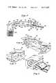
- FIG. 5is a fragmentary perspective view of the containers being received into the chamber through the inlet mouth, showing the elastomeric seal sealing to the exterior of the containers;
- FIG. 6is a fragmentary, perspective view of the filled containers being dispensed through the outlet mouth, showing the elastomeric seals sealing to the exterior of the filled containers;
- FIG. 7is a series of perspective views illustrating a method of packaging the continuous web of containers for sterilization.
- FIG. 8is a series of perspective view illustrating a method of opening the container overwrap bag to reduce contaminant entry through the opening, and showing a method of sealing this bag opening to the inlet mouth of the chamber to form a relatively sterile tunnel for the containers.
- the aseptic filling apparatus 10 of the present inventionincludes a skeletal support frame 12 formed by plural upstanding posts 14 interconnected by plural cross members 16.
- the support frame 12mounts an elongated chamber 18, having an inlet mouth 19, which forms an entry port 20 at one end of the chamber 18, and an outlet mouth 21, which forms a dispensing port 22 at the opposite end of the chamber 18, as shown in FIGS. 1 and 2.
- a continuous web of containers 24, having respective spouts 25,are fed seriatim into the entry port 20.
- Container support rollers 23(FIG. 2), horizontally mounted between the sides of the chamber 18, provide support for the containers 24 as they are advanced through the elongated chamber 18 by a passive, inclined conveyor 26, as describrd in U.S. Pat. No. 4,120,134, issued on Oct. 17, 1978, to William R. Scholle, and assigned to Scholle Corporation, which patent is hereby incorporated by reference.
- the containers 24may be advanced through the elongated chamber 18 by the mechanically driven mechanisms described in U.S. Pat. No. 4,120,134, or in copending patent application Ser. No. 245,394 entitled "Container Conveyor For a flexible Container Filling Machine", filed Mar. 19, 1981, by Roger H. Ellert, inventor, which is also hereby incorporated herein by reference.
- a filling nozzle 30, for filling the comtainers 24,extends through, and is sealed to, the top of the elongated chamber 18, near its dispensing end.
- a container spout 25When a container spout 25 reaches a position beneath this nozzle 30, it is uncapped, filled by the nozzle 30, and recapped.
- the nozzle 30is connected to a flow controller 34, mounted on the frame 12, which dispenses measured amounts of product, such as a food substance, through the spout 25 and into the container 24.
- a vertical post 36is advanced upward to cause the lower wall of the container 24 to seal off the container spout 25 prior to capping to prevent entry of air into the filled container 24. Further details of this filling mechanism, as well as a capping mechanism for uncapping and recapping the spouts 25, are provided in the above-referenced U.S. Pat. No. 4,120,134.
- This inclined conveyor 26comprises plural idle rollers 40 connected between opposing side frames 42,44.
- the side frames 42,44are rotatably connected at one end to respective brackets 46 connected to a cross member 16 of the support frame 12.
- the brackets 46are positioned to permit the conveyor 26 to receive filled containers 24 from the dispensing port 22.
- the end of the inclined conveyor opposite the dispensing port 22is supported by a post 50, which may be telescopingly adjusted to vary the angle of inclination of the inclined conveyor 26.
- a container separator 52 having a severing bar 54is connected to the side frames of the conveyor 26. This separator 52 serves to disconnect adjacent filled containers 24 at perforations, preformed in the container web between adjacent containers 24, so that the containers 24 may be deposited into protective enclosures, such as cardboard boxes.
- the elongated chamber 18is divided into a filling compartment 68, a spraying compartment 70, and a drying compartment 72.
- These compartments 68,70,72are formed by partitions 60,62, oriented perpendicularly to the longitudinal axis of the chamber 18.
- the filling compartment 68is bounded by the outlet mouth 21 on one end and the partition 60 on the other end.
- the filling nozzle 30projects into this compartment 68.
- the spraying compartmentis bounded by the inlet mouth 19 and the partition 62, while the drying compartment is bounded by the partitions 60,62.
- An elastomeric seal 64is provided across the inlet mouth 19 to seal the entry port 20.
- the outlet mouth 21is provided with two elastomeric seals 66,67, in spaced, parallel relationship, to form a double seal across the dispensing port 22.
- the partitions 60,62, and seals 64,66,67, allhave opening, described in detail below, to permit passage of the continuous web of containers 24 through the chamber 18.
- a source of sterile, heated air 76is connected by tubing (not shown) to an inlet tube 78 in the filling compartment 68 (FIG. 3) of the elongated chamber 18.
- the chamber 18also has plural spray heads 80,82,84,86 connected thereto, which are positioned to spray the compartments 70,72,68, and mouth 21, respectively.
- Each of these spray heads 80,82,84,86is connected by tubing (not shown) to the sterile air supply 76 and to a sterilant supply 88 containing, for example, a 30-percent solution of hydrogen peroxide in water.
- the spray heads 80,82,84,86atomize the hydrogen peroxide solution into a fine mist or fog, and spray such mist into the spraying compartment 70, drying compartment 72, filling compartment 68, and dispensing mouth 21, respectively.
- the elongated chamber 18, as well as the product contact surfacesshould be sterilized to ensure that filling is performed in an aseptic environment. This is accomplished by spraying the above-described hydrogen peroxide solution through each of the spray heads 80,82,84,86 simultaneously, to sterilize the entire chamber 18. Sterile air is then supplied from the air source 76 to the inlet tube 78 to maintain the filling compartment 68 at a positive pressure, and thus, in an aseptic condition. As will be described in more detail below, this sterile air flow also maintains the drying chamber 72 and dispensing mouth 21 at a positive pressure, and, therefore, also in an aseptic condition.
- the spray heads 82,84,86may be shut off.
- the spray head 80continuously operates to supply a mist of hydrogen peroxide to the spraying chamber 70, during the operation of the apparatus 10, to provide an aseptic barrier between the inlet mouth 19 and the drying compartment 72.
- the hydrogen peroxide mist in the spraying chamber 70together with the sterile air flow into the filling compartment 68, serves to prevent comtaminants from entering the elongated chamber 18.
- the product contact surfacessuch as the interior surface of the filling nozzle 30, are also sterilized prior to use of the apparatus 10. This is accomplished in a manner well known to those skilled in the art, for example, by steam sterilization techniques.
- Controllers 92monitor, record, and control the above-described processes and continually regulate flow rate, pressure, and temperature variables, such as the source temperature of the sterilized air, the air pressure in the filling compartment 68, the temperature of the air flow through the drying compartment 72, and the temperature of the steam for sterilizing the product contact surfaces.
- Windows 95are provided in the side of the chamber 18 for viewing the operation of the apparatus 10.
- the partition 62includes an opening 98, sized to permit the continuous web of containers 24 to pass therethrough.
- the contour of the opening 98is generally rectangular with a notch 100 formed along its upper edge to accommodate the filling spouts 25 of the containers 24.
- the tolerance between the edge of the opening 98 and the containers 24should be relatively close to reduce the amount of hydrogen peroxide mist passing through the opening 98. However, such tolerance should not be so close that the edges of the opening 98 wipe the web of containers 24 as they pass therethrough.
- the partition 62be formed of a flexible, resilient material so that a slight misalignment between the notch 100 and the spout 25 will not prevent advancement of the containers 24 through the opening 98.
- the partition 60has an opening 106 of generally the same conntour as the opening 98 to permit passage of the web of containers 24 therethrough, as shown in FIG. 4.
- the opening 106is substantially larger than the opening 98 to permit the previously described flow of sterile air through the inlet tube 78 (FIG. 2) to pass from the filling compartment 68, through the opening 106, and into the drying compartment 72.
- a vent tube 108is included in the bottom of the drying compartment 72, adjacent to the partition 62, to provide an outlet for the sterile air after it has travelled the length of the compartment 72.
- this flow of sterile airalso maintains a positive pressure in the drying compartment 72 and thus reduces any tendency of the hydrogen peroxide mist in the spray compartment 70 to migrate through the opening 98. Such positive pressure also prevents contaminants from entering the compartment 72 through the vent tube 108.
- a small opening 110centered at the bottom of the partition 62, adjacent to the vent 108, permits hydrogen peroxide condensate formed in the spray compartment 70 to drain through this opening 110 and into the vent 108.
- This vent 108also serves to drain any hydrogen peroxide condensate in the drying compartment 72. Accordingly, the bottom walls of the spray compartment and drying compartment are sloped towards this drain 108 to provide troughs for carrying condensate thereto.
- the vent 108is connected by tubing (not shown) to a location suitable for disposal of the hydrogen peroxide.
- the entry port seal 64is formed from an elastomeric membranous material, such as dental dam, and includes a horizontal slit 114, slightly greater in length than the width of the continuous web of containers 24 to permit such containers 24 to pass therethrough.
- the dispensing port seals 66,67, shown in FIG. 6,are identical to the entry port seal 64, except that they have respective slits 116 sized to permit filled containers 24 to pass therethrough.
- the slits 116are elastomeric so that they (a) expand to permit passage of the containers 24, and (b) seal to the outer surface of the containers 24.
- the seals 66,67, together with the positive pressure in the filling compartment 68,provide a barrier against contaminant entry through the mouth 21 and into the compartment 68.
- the aseptic filling apparatus 10 of the present inventionutilizes containers 24 which are prepackaged in a sterile container. Although such prepackaging of the containers 24 is known in the art, a description of the packaging process may be useful in fully understanding the operation of the present invention.
- the flexible containers 24are premanufactured in continuous web form, precapped, and folded at perforations between adjacent containers, in an accordian fashion.
- the folded containers 24are then placed in a sealed overwrap container 120, comprising, for example, a plastic bag.
- this overwrap bag 120is substantially greater in height than the height of the folded containers 24.
- Airis evacuated from the overwrap bag 120, and the overwrap bag 120, with the containers 24 therein, is placed in a shipping carton 122.
- the shipping carton 122is then sealed and placed in a sterilizer (not shown) to sterilize the containers 24.
- sterilizationmay be accomplished in a conventional manner, such as by radiation.
- the precapped, premanufactured, prepackaged, and presterilized containers 24are fed into the elongated chamber 18 in the manner described below.
- the carton 122is opened, and a probe 126, connected by tubing (not shown) to the sterile air source 76 (FIG. 1), is inserted through the wall of the sealed overwrap bag 120, as shown in FIG. 8, thereby causing the flow of sterile air through the probe 126 to inflate the sealed overwrap bag 120.
- An opening 128is then formed in the overwrap bag 120, as by slitting with a knife (not shown).
- this opening 128is slightly larger than the width of the web of containers 24 to permit an operator to manually grasp the end of the web of containers 24 and pull it through the opening 128. The operator then connects the leading edge of the web of containers from the overwrap bag 120 to the trailing edge 132 of the web of containers 24 which have been previously fed through the chamber 18. Such connection may be made by a pair of clips 134. It will be recognized that, although the opening 128 exposes the contents of the overwrap container 120 to the atmosphere, and thus, to contaminants, the supply of sterile air through the probe 126 will provide an air flow through the opening 128 to reduce such contamination.
- the overwrap bag 120provides a relatively sterile tunnel for passage of containers 24 from the carton 122 to the inlet mouth 19.
- the supply of sterile air through the probe 126may then be discontinued.
- the probe 126may be left in the overwrap bag 120, or alternatively, it may be removed. However, if the probe 126 is removed, it is preferable that the positive pressure in the chamber 18 be sufficiently great to create a positive pressure in the overwrap bag 120 to prevent contaminants from entering through the hole formed by the probe 126.
- the foregoing process of connecting the overwrap bag 120 to the inlet mouth 19may not be necessary in certain environments or for certain food products.
- the containers 24may be fed into the chamber 18 without providing the relatively sterile tunnel formed by the bag 120.
- the containers 24are then serially advanced through the chamber 18 by the feed means, previously discussed in reference to U.S. Pat. No. 4,120,134.
- the containers 24pass through the entry port seal 64, they enter the sterilizing chamber 70 where the continuous hydrogen peroxide mist, dispensed through the spray head 80 (FIG. 2), coats the exterior of the containers 24 to kill any microorganisms that may have contaminated the containers 24 as a result of opening the overwrap bag 120 and exposing of the containers 24 to the atmosphere.
- the rate of advancement of the containers 24 through the chamber 18is dependent upon the degree of contamination or "bio-load" on the exterior surfaces of the containers 24, and thus, this rate is regulated accordingly.
- the above-described process of using the overwrap bag to form a tunnel-like enclosurereduces the amount of time that the containers 24 are exposed to the atmosphere, and therefore, advantageously reduces the bio-load on such containers 24. Consequently, because of this reduced bio-load, the required exposure time of the containers 24 to the hydrogen peroxide mist in the compartment 70 is reduced, thereby permitting more rapid advancement of the containers 24. It will also be understood that the interior surfaces of the containers 24 need not be resterilized, since their spouts 25 are capped to prevent contaminants from entering the containers 24.
- the containers 24are then advanced from the sterilizing compartment 70 through the partition 62 and into the drying compartment 72 where the hydrogen peroxide coating thereon is dryed by a flow of heated sterile air.
- this flow of sterile airtravels from the opening 106 in the partition 60 through the entire length of the drying compartment 72 and out of the vent pipe 108.
- the temperature of this airshould be sufficient to heat the hydrogen peroxide coating without damaging the containers 24.
- Such temperaturemay, for example, be in the range of 150° F. to 190° F.
- contact heatersmay be attached to the bottom of the drying chamber to boost temperatures and reduce temperature differentials in the drying chamber 72.
- Heating of the hydrogen peroxide coatingenhances its antiseptic properties, and thus, ensures that the exterior surfaces of the containers 24 are completely sterile when they enter the filling compartment 68. Since the supply of sterile air through the inlet tube 78 (FIG. 2) maintains the filling compartment 68 in an aseptic condition, the sterilized containers 24 will remain sterile during filling. After the containers 24 have been filled, they are carried by the support rollers 23, through the dispensing port seal 66, and onto the inclined conveyor 26 where the container separator 52 (FIG. 1) separates the containers 24 for packaging.
- the present inventiontherefore, provides an aseptic environment for filling premanufactured, prepackaged, and presterilized flexible containers, connected in continuous web form.
Landscapes
- Engineering & Computer Science (AREA)
- Mechanical Engineering (AREA)
- Basic Packing Technique (AREA)
- Vacuum Packaging (AREA)
Abstract
Description
Claims (39)
Priority Applications (1)
| Application Number | Priority Date | Filing Date | Title |
|---|---|---|---|
| US06/278,344US4417607A (en) | 1981-06-29 | 1981-05-07 | Apparatus and method for aseptically filling flexible containers |
Applications Claiming Priority (1)
| Application Number | Priority Date | Filing Date | Title |
|---|---|---|---|
| US06/278,344US4417607A (en) | 1981-06-29 | 1981-05-07 | Apparatus and method for aseptically filling flexible containers |
Publications (1)
| Publication Number | Publication Date |
|---|---|
| US4417607Atrue US4417607A (en) | 1983-11-29 |
Family
ID=23064624
Family Applications (1)
| Application Number | Title | Priority Date | Filing Date |
|---|---|---|---|
| US06/278,344Expired - Fee RelatedUS4417607A (en) | 1981-06-29 | 1981-05-07 | Apparatus and method for aseptically filling flexible containers |
Country Status (1)
| Country | Link |
|---|---|
| US (1) | US4417607A (en) |
Cited By (55)
| Publication number | Priority date | Publication date | Assignee | Title |
|---|---|---|---|---|
| US4530202A (en)* | 1982-01-18 | 1985-07-23 | Aci Australia Limited | Container filling machine and method |
| US4537007A (en)* | 1982-01-29 | 1985-08-27 | Ettore Lattanzi | Process and plant for endless-cycle sterilization of sheet material utilized in aseptic packaging of pre-sterilized fluid products |
| US4676285A (en)* | 1985-04-01 | 1987-06-30 | Liqui-Box Corporation | Uncapper for containers having friction caps carrying flexible tubes |
| EP0243073A3 (en)* | 1986-04-14 | 1988-10-12 | Ex-Cell-O Corporation | Clean air system |
| US4964261A (en)* | 1989-01-24 | 1990-10-23 | Benn James A | Bag filling method and apparatus for preparing pharmaceutical sterile solutions |
| US4969915A (en)* | 1988-07-26 | 1990-11-13 | Snow Brand Milk Products Co., Ltd. | Container and method for germ-free packaging |
| US5129212A (en)* | 1990-11-08 | 1992-07-14 | Liqui-Box/B-Bar-B Corporation | Method and apparatus for automatically filling and sterilizing containers |
| USD342530S (en) | 1991-12-16 | 1993-12-21 | Minnesota Mining And Manufacturing Company | Case sealer |
| US5322095A (en)* | 1991-06-25 | 1994-06-21 | Alfred Bolz Gmbh & Co. Kg | Filling plant for hazardous media |
| US5341854A (en)* | 1989-09-28 | 1994-08-30 | Alberta Research Council | Robotic drug dispensing system |
| US5447699A (en)* | 1993-11-17 | 1995-09-05 | The West Company | Combination container for holding sterilized elements and a sterilizable transfer port |
| US5518049A (en)* | 1993-08-05 | 1996-05-21 | Compagnie Generale Des Matieres Nucleaires | Device for filling a receptacle closed by a needle and provided with cleaning means |
| US5518046A (en)* | 1993-06-21 | 1996-05-21 | Fuji Photo Film Co., Ltd. | Method for charging liquids into containers |
| US5533550A (en)* | 1994-09-30 | 1996-07-09 | Tetra Laval Holdings & Finance S.A. | Tank venting apparatus for a packaging machine |
| WO1997042897A1 (en)* | 1996-05-13 | 1997-11-20 | B. Braun Medical | Flexible, multiple-compartment drug container and method of making and using same |
| US5797436A (en)* | 1995-06-26 | 1998-08-25 | Oden Corporation | Liquid filling machine technical field |
| WO1998038091A1 (en)* | 1997-02-26 | 1998-09-03 | Baxter International Inc. | Method and apparatus for manufacturing intravenous solution bags |
| US5829493A (en)* | 1996-09-06 | 1998-11-03 | Campbell Soup Company | Apparatus for filling containers with a liquid |
| US5858040A (en)* | 1997-03-28 | 1999-01-12 | Tetra Laval Holdings & Finance, Sa | Filling machine having a microfiltrated clean air supply system |
| US5881535A (en)* | 1996-04-09 | 1999-03-16 | Baxter International, Inc. | Apparatus and method for filling and sealing intravenous solution bags |
| US5896872A (en)* | 1998-02-17 | 1999-04-27 | Coastlog Industries, Ltd. (U.S.A.) | Method for cleaning and sanitizing packages containing an edible product |
| US5910138A (en)* | 1996-05-13 | 1999-06-08 | B. Braun Medical, Inc. | Flexible medical container with selectively enlargeable compartments and method for making same |
| NL1007864C2 (en)* | 1997-12-22 | 1999-06-23 | Meurs Holding B V Maschf Van | Sterilising surface of opening in flexible container for e.g. liquid foodstuffs during a filling process |
| US5928213A (en)* | 1996-05-13 | 1999-07-27 | B. Braun Medical, Inc. | Flexible multiple compartment medical container with preferentially rupturable seals |
| US5944709A (en)* | 1996-05-13 | 1999-08-31 | B. Braun Medical, Inc. | Flexible, multiple-compartment drug container and method of making and using same |
| EP0793968A3 (en)* | 1996-03-04 | 2000-02-23 | Eastman Kodak Company | Method for heating and venting a container |
| US6070622A (en)* | 1998-05-07 | 2000-06-06 | Packaging Systems, L.L.C. | High speed aseptic filling machine |
| EP1116664A1 (en)* | 2000-01-11 | 2001-07-18 | The Quaker Oats Company | Sterilization system and method for food packaging |
| USRE37471E1 (en) | 1994-03-02 | 2001-12-18 | Robert Bosch Packaging Technology, Inc. | Vial filling apparatus |
| US20040079438A1 (en)* | 2001-01-29 | 2004-04-29 | Pascal Bruna | Assembly and method for making, mounting and filling a fluid product dispensing device |
| US20050039819A1 (en)* | 2003-08-21 | 2005-02-24 | Shaun Peltier | System for sanitary water filling and dispensing |
| USRE38747E1 (en) | 1994-03-02 | 2005-06-28 | Robert Bosch Packaging Technology, Inc. | Vial filling apparatus |
| US20070119121A1 (en)* | 2005-11-28 | 2007-05-31 | Pdc Facilities, Inc. | Filling machine |
| US7241066B1 (en) | 2003-04-15 | 2007-07-10 | American Grease Stick Company | Container for flowable products |
| CN100453306C (en)* | 2005-08-18 | 2009-01-21 | 湖南千山制药机械股份有限公司 | Double-hose double-chamber infusion bag making machine capable of holding solid medicine and liquid medicine |
| CN100453307C (en)* | 2005-08-18 | 2009-01-21 | 湖南千山制药机械股份有限公司 | Double flexible pipe double solid chamber transfusion bag manufacturing machine for solid drug and liquid drug |
| CN100453308C (en)* | 2005-08-08 | 2009-01-21 | 湖南千山制药机械股份有限公司 | Bag making machine for hard single-mouth pipe two chamber infusion bag holding liquid medicine and solid medicine |
| CN100453305C (en)* | 2005-08-02 | 2009-01-21 | 湖南千山制药机械股份有限公司 | Single-mouth tube double-chamber infusion bag making machine capable of holding solid medicine and liquid medicine |
| US7513218B1 (en) | 2004-09-14 | 2009-04-07 | Edstrom Industries, Inc. | Potable water delivery system for animals |
| US20090094940A1 (en)* | 2007-10-04 | 2009-04-16 | Daniel Py | Apparatus for formulating and aseptically filling liquid products |
| US20110071009A1 (en)* | 2008-03-25 | 2011-03-24 | Sarong Societa' Per Azioni | Apparatus for forming aseptic containers |
| WO2011127691A1 (en)* | 2010-04-14 | 2011-10-20 | 楚天科技股份有限公司 | Self-adaptive partition board assembly for tunnel type sterilizing dryer |
| US8061563B1 (en) | 2007-05-29 | 2011-11-22 | Ags I-Prop, Llc | Flexible pouch with expulsion aid |
| US20120160927A1 (en)* | 2009-04-25 | 2012-06-28 | Nestec S.A. | Water fountain |
| US20120312415A1 (en)* | 2010-02-10 | 2012-12-13 | Sartorius Stedim Biotech | Method and unit for the sterile filling of a final basic container with content intended for the biopharmaceutical field |
| US8376183B1 (en) | 2008-06-10 | 2013-02-19 | Ags I-Prop, Llc | Fluid dispenser having multiple chambers |
| US20150020480A1 (en)* | 2012-02-13 | 2015-01-22 | Jerome Anzio Harris | Method and system for filling bladder members |
| WO2015044087A1 (en)* | 2013-09-25 | 2015-04-02 | Fresenius Kabi Deutschland Gmbh | Food arrangement |
| US20150175281A1 (en)* | 2012-04-13 | 2015-06-25 | Dr. Py Institute Llc | Modular Filling Apparatus and Method |
| US20150239594A1 (en)* | 2014-02-26 | 2015-08-27 | Mead Johnson Nutrition Company | Methods for aseptic packaging of low-acid foods |
| US10940966B2 (en)* | 2018-03-01 | 2021-03-09 | Storopack Hans Reichenecker Gmbh | Machine and method for producing cushioning material |
| US11679171B2 (en) | 2021-06-08 | 2023-06-20 | Steribin, LLC | Apparatus and method for disinfecting substances as they pass through a pipe |
| US11980587B2 (en) | 2020-11-25 | 2024-05-14 | Deka Products Limited Partnership | Systems, methods, and apparatuses for producing and packaging fluids |
| US12195216B1 (en)* | 2023-06-16 | 2025-01-14 | Torr Industries, Inc. | Bag transporting and filling apparatus |
| US12221364B2 (en) | 2019-11-25 | 2025-02-11 | Deka Products Limited Partnership | Systems, methods, and apparatuses for producing and packaging fluids |
Citations (4)
| Publication number | Priority date | Publication date | Assignee | Title |
|---|---|---|---|---|
| US3828833A (en)* | 1969-05-08 | 1974-08-13 | Heinz Co H J | Aseptic container filling apparatus |
| US3913634A (en)* | 1974-01-25 | 1975-10-21 | Solbern Corp | Machine for filling containers with granular products |
| US4120134A (en)* | 1977-07-05 | 1978-10-17 | Scholle Corporation | Apparatus for and method of filling flexible containers |
| US4208852A (en)* | 1974-11-08 | 1980-06-24 | Pont-A-Mousson S.A. | Process for the aseptic packing of products and machine employing said process |
- 1981
- 1981-05-07USUS06/278,344patent/US4417607A/ennot_activeExpired - Fee Related
Patent Citations (4)
| Publication number | Priority date | Publication date | Assignee | Title |
|---|---|---|---|---|
| US3828833A (en)* | 1969-05-08 | 1974-08-13 | Heinz Co H J | Aseptic container filling apparatus |
| US3913634A (en)* | 1974-01-25 | 1975-10-21 | Solbern Corp | Machine for filling containers with granular products |
| US4208852A (en)* | 1974-11-08 | 1980-06-24 | Pont-A-Mousson S.A. | Process for the aseptic packing of products and machine employing said process |
| US4120134A (en)* | 1977-07-05 | 1978-10-17 | Scholle Corporation | Apparatus for and method of filling flexible containers |
Cited By (82)
| Publication number | Priority date | Publication date | Assignee | Title |
|---|---|---|---|---|
| US4530202A (en)* | 1982-01-18 | 1985-07-23 | Aci Australia Limited | Container filling machine and method |
| US4537007A (en)* | 1982-01-29 | 1985-08-27 | Ettore Lattanzi | Process and plant for endless-cycle sterilization of sheet material utilized in aseptic packaging of pre-sterilized fluid products |
| US4676285A (en)* | 1985-04-01 | 1987-06-30 | Liqui-Box Corporation | Uncapper for containers having friction caps carrying flexible tubes |
| EP0243073A3 (en)* | 1986-04-14 | 1988-10-12 | Ex-Cell-O Corporation | Clean air system |
| US4969915A (en)* | 1988-07-26 | 1990-11-13 | Snow Brand Milk Products Co., Ltd. | Container and method for germ-free packaging |
| US4964261A (en)* | 1989-01-24 | 1990-10-23 | Benn James A | Bag filling method and apparatus for preparing pharmaceutical sterile solutions |
| US5341854A (en)* | 1989-09-28 | 1994-08-30 | Alberta Research Council | Robotic drug dispensing system |
| US5129212A (en)* | 1990-11-08 | 1992-07-14 | Liqui-Box/B-Bar-B Corporation | Method and apparatus for automatically filling and sterilizing containers |
| US5322095A (en)* | 1991-06-25 | 1994-06-21 | Alfred Bolz Gmbh & Co. Kg | Filling plant for hazardous media |
| USD342530S (en) | 1991-12-16 | 1993-12-21 | Minnesota Mining And Manufacturing Company | Case sealer |
| US5518046A (en)* | 1993-06-21 | 1996-05-21 | Fuji Photo Film Co., Ltd. | Method for charging liquids into containers |
| US5518049A (en)* | 1993-08-05 | 1996-05-21 | Compagnie Generale Des Matieres Nucleaires | Device for filling a receptacle closed by a needle and provided with cleaning means |
| US5447699A (en)* | 1993-11-17 | 1995-09-05 | The West Company | Combination container for holding sterilized elements and a sterilizable transfer port |
| USRE38747E1 (en) | 1994-03-02 | 2005-06-28 | Robert Bosch Packaging Technology, Inc. | Vial filling apparatus |
| USRE37471E1 (en) | 1994-03-02 | 2001-12-18 | Robert Bosch Packaging Technology, Inc. | Vial filling apparatus |
| US5533550A (en)* | 1994-09-30 | 1996-07-09 | Tetra Laval Holdings & Finance S.A. | Tank venting apparatus for a packaging machine |
| US5797436A (en)* | 1995-06-26 | 1998-08-25 | Oden Corporation | Liquid filling machine technical field |
| EP0793968A3 (en)* | 1996-03-04 | 2000-02-23 | Eastman Kodak Company | Method for heating and venting a container |
| US5881535A (en)* | 1996-04-09 | 1999-03-16 | Baxter International, Inc. | Apparatus and method for filling and sealing intravenous solution bags |
| US6203535B1 (en) | 1996-05-13 | 2001-03-20 | B. Braun Medical, Inc. | Method of making and using a flexible, multiple-compartment drug container |
| US5910138A (en)* | 1996-05-13 | 1999-06-08 | B. Braun Medical, Inc. | Flexible medical container with selectively enlargeable compartments and method for making same |
| WO1997042897A1 (en)* | 1996-05-13 | 1997-11-20 | B. Braun Medical | Flexible, multiple-compartment drug container and method of making and using same |
| US5928213A (en)* | 1996-05-13 | 1999-07-27 | B. Braun Medical, Inc. | Flexible multiple compartment medical container with preferentially rupturable seals |
| US5944709A (en)* | 1996-05-13 | 1999-08-31 | B. Braun Medical, Inc. | Flexible, multiple-compartment drug container and method of making and using same |
| US6996951B2 (en) | 1996-05-13 | 2006-02-14 | B. Braun Medical Inc. | Flexible multi-compartment container with peelable seals and method for making same |
| US6846305B2 (en) | 1996-05-13 | 2005-01-25 | B. Braun Medical Inc. | Flexible multi-compartment container with peelable seals and method for making same |
| US6165161A (en)* | 1996-05-13 | 2000-12-26 | B. Braun Medical, Inc. | Sacrificial port for filling flexible, multiple-compartment drug container |
| US6198106B1 (en) | 1996-05-13 | 2001-03-06 | B. Braun Medical, Inc. | Transport and sterilization carrier for flexible, multiple compartment drug container |
| US6764567B2 (en) | 1996-05-13 | 2004-07-20 | B. Braun Medical | Flexible medical container with selectively enlargeable compartments and method for making same |
| US6468377B1 (en) | 1996-05-13 | 2002-10-22 | B. Braun Medical Inc. | Flexible medical container with selectively enlargeable compartments and method for making same |
| US5829493A (en)* | 1996-09-06 | 1998-11-03 | Campbell Soup Company | Apparatus for filling containers with a liquid |
| WO1998038091A1 (en)* | 1997-02-26 | 1998-09-03 | Baxter International Inc. | Method and apparatus for manufacturing intravenous solution bags |
| US5858040A (en)* | 1997-03-28 | 1999-01-12 | Tetra Laval Holdings & Finance, Sa | Filling machine having a microfiltrated clean air supply system |
| NL1007864C2 (en)* | 1997-12-22 | 1999-06-23 | Meurs Holding B V Maschf Van | Sterilising surface of opening in flexible container for e.g. liquid foodstuffs during a filling process |
| US5896872A (en)* | 1998-02-17 | 1999-04-27 | Coastlog Industries, Ltd. (U.S.A.) | Method for cleaning and sanitizing packages containing an edible product |
| US6148874A (en)* | 1998-05-07 | 2000-11-21 | Packaging Systems, L.L.C. | Filling head mechanism that removes material from a spout of a filled container before completely disengaging from the spout |
| US6070622A (en)* | 1998-05-07 | 2000-06-06 | Packaging Systems, L.L.C. | High speed aseptic filling machine |
| EP1116664A1 (en)* | 2000-01-11 | 2001-07-18 | The Quaker Oats Company | Sterilization system and method for food packaging |
| US20040079438A1 (en)* | 2001-01-29 | 2004-04-29 | Pascal Bruna | Assembly and method for making, mounting and filling a fluid product dispensing device |
| US7503355B2 (en)* | 2001-01-29 | 2009-03-17 | Valois S.A.S | Assembly and method for making, mounting and filling a fluid product dispensing device |
| US7241066B1 (en) | 2003-04-15 | 2007-07-10 | American Grease Stick Company | Container for flowable products |
| US7007725B2 (en)* | 2003-08-21 | 2006-03-07 | Shaun Peltier | System for sanitary water filling and dispensing |
| US20050039819A1 (en)* | 2003-08-21 | 2005-02-24 | Shaun Peltier | System for sanitary water filling and dispensing |
| US8056510B2 (en) | 2004-09-14 | 2011-11-15 | Edstrom Industries, Inc. | Potable water delivery system for animals |
| US20090223462A1 (en)* | 2004-09-14 | 2009-09-10 | Edstrom Inudustries, Inc. | Potable water delivery system for animals |
| US7513218B1 (en) | 2004-09-14 | 2009-04-07 | Edstrom Industries, Inc. | Potable water delivery system for animals |
| CN100453305C (en)* | 2005-08-02 | 2009-01-21 | 湖南千山制药机械股份有限公司 | Single-mouth tube double-chamber infusion bag making machine capable of holding solid medicine and liquid medicine |
| CN100453308C (en)* | 2005-08-08 | 2009-01-21 | 湖南千山制药机械股份有限公司 | Bag making machine for hard single-mouth pipe two chamber infusion bag holding liquid medicine and solid medicine |
| CN100453307C (en)* | 2005-08-18 | 2009-01-21 | 湖南千山制药机械股份有限公司 | Double flexible pipe double solid chamber transfusion bag manufacturing machine for solid drug and liquid drug |
| CN100453306C (en)* | 2005-08-18 | 2009-01-21 | 湖南千山制药机械股份有限公司 | Double-hose double-chamber infusion bag making machine capable of holding solid medicine and liquid medicine |
| US7484345B2 (en) | 2005-11-28 | 2009-02-03 | Pdc Facilities, Inc. | Filling machine |
| US20070119121A1 (en)* | 2005-11-28 | 2007-05-31 | Pdc Facilities, Inc. | Filling machine |
| US8061563B1 (en) | 2007-05-29 | 2011-11-22 | Ags I-Prop, Llc | Flexible pouch with expulsion aid |
| EP2207427A4 (en)* | 2007-10-04 | 2012-06-20 | Medical Instill Tech Inc | APPARATUS AND METHOD FOR ASEPTIC FORMULATION AND FILLING OF LIQUID PRODUCTS |
| US20090094940A1 (en)* | 2007-10-04 | 2009-04-16 | Daniel Py | Apparatus for formulating and aseptically filling liquid products |
| US20090098250A1 (en)* | 2007-10-04 | 2009-04-16 | Daniel Py | Method for formulating and aseptically filling liquid products |
| US8646243B2 (en) | 2007-10-04 | 2014-02-11 | Medical Instill Technologies, Inc. | Apparatus for formulating and aseptically filling liquid products |
| US8663080B2 (en)* | 2008-03-25 | 2014-03-04 | Sarong Societa' Per Azioni | Apparatus for forming aseptic containers |
| US20110071009A1 (en)* | 2008-03-25 | 2011-03-24 | Sarong Societa' Per Azioni | Apparatus for forming aseptic containers |
| US8376183B1 (en) | 2008-06-10 | 2013-02-19 | Ags I-Prop, Llc | Fluid dispenser having multiple chambers |
| US20120160927A1 (en)* | 2009-04-25 | 2012-06-28 | Nestec S.A. | Water fountain |
| US9117326B2 (en)* | 2009-04-25 | 2015-08-25 | Nestec S.A. | Apparatus for packaging drinking water |
| US20120312415A1 (en)* | 2010-02-10 | 2012-12-13 | Sartorius Stedim Biotech | Method and unit for the sterile filling of a final basic container with content intended for the biopharmaceutical field |
| US12330824B2 (en) | 2010-02-10 | 2025-06-17 | Sartorius Stedim Fmt | Unit for the sterile filling of a final basic container with contents designed for the biopharmaceutical field |
| US11655058B2 (en) | 2010-02-10 | 2023-05-23 | Sartorius Stedim Fmt Sas | Unit for the sterile filling of a final basic container with contents designed for the biopharmaceutical field |
| US10793299B2 (en)* | 2010-02-10 | 2020-10-06 | Sartorius Stedim Fmt Sas | Method and unit for the sterile filling of a final basic container with content intended for the biopharmaceutical field |
| WO2011127691A1 (en)* | 2010-04-14 | 2011-10-20 | 楚天科技股份有限公司 | Self-adaptive partition board assembly for tunnel type sterilizing dryer |
| US20150020480A1 (en)* | 2012-02-13 | 2015-01-22 | Jerome Anzio Harris | Method and system for filling bladder members |
| US10273025B2 (en)* | 2012-04-13 | 2019-04-30 | Dr. Py Institute Llc | Modular filling apparatus and method |
| US20150175281A1 (en)* | 2012-04-13 | 2015-06-25 | Dr. Py Institute Llc | Modular Filling Apparatus and Method |
| WO2015044087A1 (en)* | 2013-09-25 | 2015-04-02 | Fresenius Kabi Deutschland Gmbh | Food arrangement |
| CN105592837A (en)* | 2013-09-25 | 2016-05-18 | 费森尤斯卡比德国有限公司 | Nutrient device |
| US10543944B2 (en)* | 2014-02-26 | 2020-01-28 | Mead Johnson Nutrition Company | Methods for aseptic packaging of low-acid foods |
| CN106029336B (en)* | 2014-02-26 | 2020-05-22 | Mjn 美国控股有限责任公司 | Method for aseptic packaging of low-acid food |
| CN106029336A (en)* | 2014-02-26 | 2016-10-12 | Mjn 美国控股有限责任公司 | Method for aseptic packaging of low-acid food |
| US20150239594A1 (en)* | 2014-02-26 | 2015-08-27 | Mead Johnson Nutrition Company | Methods for aseptic packaging of low-acid foods |
| US10940966B2 (en)* | 2018-03-01 | 2021-03-09 | Storopack Hans Reichenecker Gmbh | Machine and method for producing cushioning material |
| US12221364B2 (en) | 2019-11-25 | 2025-02-11 | Deka Products Limited Partnership | Systems, methods, and apparatuses for producing and packaging fluids |
| US11980587B2 (en) | 2020-11-25 | 2024-05-14 | Deka Products Limited Partnership | Systems, methods, and apparatuses for producing and packaging fluids |
| US12239607B2 (en) | 2020-11-25 | 2025-03-04 | Deka Products Limited Partnership | Systems, methods, and apparatuses for producing and packaging fluids |
| US11679171B2 (en) | 2021-06-08 | 2023-06-20 | Steribin, LLC | Apparatus and method for disinfecting substances as they pass through a pipe |
| US12195216B1 (en)* | 2023-06-16 | 2025-01-14 | Torr Industries, Inc. | Bag transporting and filling apparatus |
Similar Documents
| Publication | Publication Date | Title |
|---|---|---|
| US4417607A (en) | Apparatus and method for aseptically filling flexible containers | |
| US3566575A (en) | Aseptic packaging machine | |
| US3911640A (en) | Method for the packing under aseptic conditions of sterile goods into containers | |
| US6475435B1 (en) | Apparatus and method for providing sterilization zones in an aseptic packaging sterilization tunnel | |
| US3723060A (en) | Aseptic packaging machine | |
| CA2663712C (en) | Method and apparatus for aseptically packaging foods | |
| WO1982003832A1 (en) | Apparatus and method for aseptically filling flexible containers | |
| US3086336A (en) | Apparatus for producing aseptic packages | |
| US5053196A (en) | Method for container conveyance in germ-free filling/packaging system | |
| US4391080A (en) | Method for providing an inert sterile atmosphere in an aseptic packaging machine | |
| WO2010044025A1 (en) | A method of forming and filling food containers. | |
| KR20040086335A (en) | Unit for sterilizing web-fed material on a machine for packaging pourable food products | |
| JP4651775B2 (en) | Unit for sterilizing strip packaging materials | |
| EP0290139A2 (en) | Apparatus for sterilizing film and like packaging material | |
| US6101786A (en) | Filling machine | |
| GB2115767A (en) | Apparatus and method for aseptically filling flexible containers | |
| US3401043A (en) | Aseptic packaging of fluid food products | |
| JPH0958635A (en) | Aseptic filling and packaging apparatus and sterilization method of aseptic filling and packaging apparatus | |
| US20010000558A1 (en) | Apparatus and method for providing container lidding and sealing in an aseptic processing apparatus | |
| JP7447424B2 (en) | Aseptic filling machine and aseptic filling method | |
| JPH0958632A (en) | Packaging material sterilizer | |
| JP2556064B2 (en) | Aseptic packaging machine | |
| JPH0815901B2 (en) | Packaging material sterilizer | |
| JP7307396B2 (en) | Aseptic filling machine and aseptic filling method | |
| EP1812295B1 (en) | Apparatus and method for filling containers |
Legal Events
| Date | Code | Title | Description |
|---|---|---|---|
| AS | Assignment | Owner name:SCHOLLE CORPORATION, 19500 JAMBOREE RD. IRVINE, CA Free format text:ASSIGNMENT OF ASSIGNORS INTEREST.;ASSIGNORS:SCHOLLE, WILLIAM R.;SCHOLLE, WILLIAM J.;GUNNING, MICHAEL J.;REEL/FRAME:003898/0177;SIGNING DATES FROM 19810615 TO 19810619 | |
| MAFP | Maintenance fee payment | Free format text:PAYMENT OF MAINTENANCE FEE, 4TH YEAR, PL 96-517 (ORIGINAL EVENT CODE: M170); ENTITY STATUS OF PATENT OWNER: LARGE ENTITY Year of fee payment:4 | |
| MAFP | Maintenance fee payment | Free format text:PAYMENT OF MAINTENANCE FEE, 8TH YEAR, PL 96-517 (ORIGINAL EVENT CODE: M171); ENTITY STATUS OF PATENT OWNER: LARGE ENTITY Year of fee payment:8 | |
| FEPP | Fee payment procedure | Free format text:PAYOR NUMBER ASSIGNED (ORIGINAL EVENT CODE: ASPN); ENTITY STATUS OF PATENT OWNER: LARGE ENTITY | |
| FEPP | Fee payment procedure | Free format text:MAINTENANCE FEE REMINDER MAILED (ORIGINAL EVENT CODE: REM.); ENTITY STATUS OF PATENT OWNER: LARGE ENTITY | |
| LAPS | Lapse for failure to pay maintenance fees | ||
| FP | Lapsed due to failure to pay maintenance fee | Effective date:19951129 | |
| AS | Assignment | Owner name:BANK OF AMERICA, N.A., ILLINOIS Free format text:SECURITY AGREEMENT;ASSIGNOR:SCHOLLE CORPORATION;REEL/FRAME:016069/0612 Effective date:20050407 | |
| STCH | Information on status: patent discontinuation | Free format text:PATENT EXPIRED DUE TO NONPAYMENT OF MAINTENANCE FEES UNDER 37 CFR 1.362 | |
| AS | Assignment | Owner name:SCHOLLE IPN CORPORATION, ILLINOIS Free format text:RELEASE BY SECURED PARTY;ASSIGNOR:BANK OF AMERICA, N.A.;REEL/FRAME:047139/0879 Effective date:20170727 |