US4416277A - Return electrode monitoring system for use during electrosurgical activation - Google Patents
Return electrode monitoring system for use during electrosurgical activationDownload PDFInfo
- Publication number
- US4416277A US4416277AUS06/317,780US31778081AUS4416277AUS 4416277 AUS4416277 AUS 4416277AUS 31778081 AUS31778081 AUS 31778081AUS 4416277 AUS4416277 AUS 4416277A
- Authority
- US
- United States
- Prior art keywords
- electrode
- impedance
- patient
- conductors
- upper limit
- Prior art date
- Legal status (The legal status is an assumption and is not a legal conclusion. Google has not performed a legal analysis and makes no representation as to the accuracy of the status listed.)
- Expired - Lifetime
Links
- 238000012544monitoring processMethods0.000titleclaimsabstractdescription25
- 230000004913activationEffects0.000titledescription5
- 239000004020conductorSubstances0.000claimsabstractdescription26
- 230000000694effectsEffects0.000claimsabstractdescription5
- 239000011888foilSubstances0.000claimsdescription13
- 238000004804windingMethods0.000claimsdescription8
- 230000001360synchronised effectEffects0.000claimsdescription5
- 230000003247decreasing effectEffects0.000claimsdescription4
- 230000007704transitionEffects0.000claims5
- 230000008878couplingEffects0.000claims1
- 238000010168coupling processMethods0.000claims1
- 238000005859coupling reactionMethods0.000claims1
- 230000003044adaptive effectEffects0.000description16
- 230000006870functionEffects0.000description7
- 239000003990capacitorSubstances0.000description4
- 230000007423decreaseEffects0.000description4
- 238000001514detection methodMethods0.000description4
- 238000010586diagramMethods0.000description4
- 230000001052transient effectEffects0.000description4
- 210000000577adipose tissueAnatomy0.000description2
- 238000001035dryingMethods0.000description2
- 238000001356surgical procedureMethods0.000description2
- 206010015150ErythemaDiseases0.000description1
- 230000006978adaptationEffects0.000description1
- 230000005540biological transmissionEffects0.000description1
- 238000004590computer programMethods0.000description1
- 238000010276constructionMethods0.000description1
- 238000013461designMethods0.000description1
- 231100000321erythemaToxicity0.000description1
- 238000010438heat treatmentMethods0.000description1
- 230000003902lesionEffects0.000description1
- 238000005259measurementMethods0.000description1
- 238000000034methodMethods0.000description1
- 210000003205muscleAnatomy0.000description1
- 230000002028prematureEffects0.000description1
- 238000012545processingMethods0.000description1
- 231100000241scarToxicity0.000description1
- 230000035945sensitivityEffects0.000description1
- 239000007787solidSubstances0.000description1
- 238000012360testing methodMethods0.000description1
- 210000001519tissueAnatomy0.000description1
- 230000000007visual effectEffects0.000description1
Images


Classifications
- A—HUMAN NECESSITIES
- A61—MEDICAL OR VETERINARY SCIENCE; HYGIENE
- A61B—DIAGNOSIS; SURGERY; IDENTIFICATION
- A61B18/00—Surgical instruments, devices or methods for transferring non-mechanical forms of energy to or from the body
- A61B18/04—Surgical instruments, devices or methods for transferring non-mechanical forms of energy to or from the body by heating
- A61B18/12—Surgical instruments, devices or methods for transferring non-mechanical forms of energy to or from the body by heating by passing a current through the tissue to be heated, e.g. high-frequency current
- A61B18/1206—Generators therefor
- A61B18/1233—Generators therefor with circuits for assuring patient safety
- A—HUMAN NECESSITIES
- A61—MEDICAL OR VETERINARY SCIENCE; HYGIENE
- A61B—DIAGNOSIS; SURGERY; IDENTIFICATION
- A61B18/00—Surgical instruments, devices or methods for transferring non-mechanical forms of energy to or from the body
- A61B18/04—Surgical instruments, devices or methods for transferring non-mechanical forms of energy to or from the body by heating
- A61B18/12—Surgical instruments, devices or methods for transferring non-mechanical forms of energy to or from the body by heating by passing a current through the tissue to be heated, e.g. high-frequency current
- A61B18/14—Probes or electrodes therefor
- A61B18/16—Indifferent or passive electrodes for grounding
- A—HUMAN NECESSITIES
- A61—MEDICAL OR VETERINARY SCIENCE; HYGIENE
- A61B—DIAGNOSIS; SURGERY; IDENTIFICATION
- A61B18/00—Surgical instruments, devices or methods for transferring non-mechanical forms of energy to or from the body
- A61B2018/00636—Sensing and controlling the application of energy
- A61B2018/00666—Sensing and controlling the application of energy using a threshold value
- A61B2018/00678—Sensing and controlling the application of energy using a threshold value upper
- A—HUMAN NECESSITIES
- A61—MEDICAL OR VETERINARY SCIENCE; HYGIENE
- A61B—DIAGNOSIS; SURGERY; IDENTIFICATION
- A61B18/00—Surgical instruments, devices or methods for transferring non-mechanical forms of energy to or from the body
- A61B2018/00636—Sensing and controlling the application of energy
- A61B2018/00696—Controlled or regulated parameters
- A61B2018/00755—Resistance or impedance
- A—HUMAN NECESSITIES
- A61—MEDICAL OR VETERINARY SCIENCE; HYGIENE
- A61B—DIAGNOSIS; SURGERY; IDENTIFICATION
- A61B18/00—Surgical instruments, devices or methods for transferring non-mechanical forms of energy to or from the body
- A61B2018/00636—Sensing and controlling the application of energy
- A61B2018/00773—Sensed parameters
- A61B2018/00875—Resistance or impedance
- Y—GENERAL TAGGING OF NEW TECHNOLOGICAL DEVELOPMENTS; GENERAL TAGGING OF CROSS-SECTIONAL TECHNOLOGIES SPANNING OVER SEVERAL SECTIONS OF THE IPC; TECHNICAL SUBJECTS COVERED BY FORMER USPC CROSS-REFERENCE ART COLLECTIONS [XRACs] AND DIGESTS
- Y10—TECHNICAL SUBJECTS COVERED BY FORMER USPC
- Y10S—TECHNICAL SUBJECTS COVERED BY FORMER USPC CROSS-REFERENCE ART COLLECTIONS [XRACs] AND DIGESTS
- Y10S128/00—Surgery
- Y10S128/908—Patient protection from electric shock
Definitions
- This inventionis directed to electrosurgery and, in particular, to circuitry for monitoring patient return electrodes employed in such surgery.
- the above systemsare subject to at least one or more of the following shortcomings: (a) lack of sensitivity or adaptiveness to different physiological characteristics of patients and (b) susceptibility to electrosurgical current interference when monitoring is continued during electrosurgical activation.
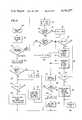
- FIG. 1is a block diagram of an illustrative system in accordance with the invention.
- FIG. 1Ais a diagrammatic illustration of a common foil electrode and associated cable for use in the system of FIG. 1.
- FIG. 2is a diagrammatic illustration indicating physiological characteristics affecting the impedance between the elements of a split patient electrode when the electrode is in contact with a patient's skin.
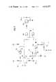
- FIG. 3is a schematic diagram of the patient impedance detection circuitry of FIG. 1.
- FIG. 4is a graph illustrating the operation of the adaptive threshold circuitry of FIG. 1.
- FIGS. 5A and 5Bare a flow chart of a program for implementing the operation illustrated by FIG. 4.
- FIG. 6is a flow chart of a program for implementing a non-adaptive threshold function.
- FIG. 7is a schematic diagram of circuitry for implementing a non-adaptive function.
- electrosurgical generator 10may include known circuitry such as a radio frequency oscillator 12 and an output amplifier 14 which generate an electrosurgical current. This current is applied to a patient (not shown) via an active electrode 16.
- the electrosurgical currentis returned to the generator 10 via a split return electrode 18 comrising electrodes 20 and 22 and a two conductor patient cable 24 comprising leads 26 and 28.
- the split return electrodemay be of the type shown in above-mentioned U.S. Pat. No. 4,200,104.
- the electrosurgical currentis then returned to amplfier 14 via a lead 30 connected between capacitors 32 and 34. These capacitors are connected across the secondary winding 36 of a transformer 38.
- the primary winding 40 of the transformeris connected to patient impedance detecting circuitry 42, the purpose of which is to produce a voltage EREM which is a function of the impedance between electrodes 20 and 22.
- EREMis applied to adaptive threshold circuitry 44 which determines whether the above impedance is within a desired range, the range being preferably adaptable to the physiological characteristics of the patient. If it is not, an inhibit signal is applied over a line 46 to internally disable the generator.
- a plug attached to the generator end of two conductor cable 24is insertable into a patient connector which is incorporated in generator 10.
- the plug/connector arrangementis diagrammatically indicated at 47 and 49.
- a switch 51 in the connectoris also provided to indicate the mode of operation of the system. That is, in a first mode, the system employs the split patient electrode 18 of FIG. 1.
- Incorporated in the plug for the split patient return electrode cableis a pin which activates switch 51 to thereby indicate over lines 61 and 63 to adaptive threshold circuitry 44 the system is operating in its first mode--that is, with a split patient electrode.
- FIG. 1ADiagrammatically illustrated in FIG. 1A is an electrode arrangement employed in a second mode of operation of the system, the electrode 53 comprising a common foil having connected thereto at spaced apart points the leads 55 and 57 of a two conductor cable 59.
- a plug attached to the generator end of the cableis insertable in the connector disposed at the generator. However, it does not include a pin corresponding to that described above.
- switch 51is not activated. Accordingly, an indication is provided over lines 61 and 63 the system is cooperating in its second mode of operation.
- patient impedance detection circuitry 42is shown connected to electrodes 20 and 22 which in turn are in contact with the patient's skin. Further, the physiological characteristics of the patient's skin, adipose and muscle layers are diagrmmatically indicated by resistances. As will be described in detail hereinafter, detection circuitry 42 applies a constant, physiologically benign, monitor current (typially 140 kHz, 2 mA) to conductor 26 which passes through electrode 20 and the patient and then returns to ciruitry 42 via electrode 22 and conductor 28. Circuitry 42 processes the voltage appearing across conductors 26 and 28 to provide EREM which, as stated above, is a measurement of the impendance between electrodes 20 and 22.
- monitor currenttypially 140 kHz, 2 mA
- Adaptive threshold circuitry 44typically establishes a range, which may extend from 20 to 144 ohms, within which the impedance between the electrodes (pads) 20 and 22 must fall. If not, the generator 10 is disabled. Thus, the lower limit is fixed at the nominal value of 20 ohms whereby such hazards as applying the electrode to a surface other than the patient may be avoided.
- the upper limitis set to avoid such problems as those mentioned hereinbefore--that is, tenting, incorrect application site, gel drying, etc.
- the upper limitis adjustable from the absolute maximum (typically 144 ohms) downward to as low as typically 20 ohms to thereby provide for automatic adaptiveness to the physiological characteristics of the patient.
- Thisprovides the monitor of the present invention with significantly more control over the integrity of the return electrode connection without limiting the range of patient types with which the system may be used or burdening the operator with additional concerns. That is, the physiological characteristics indicated in FIG. 2 can very significantly from patient to patient and from one location site for the return electrode to another. Thus, patients, of course, vary in their respective amounts of adipose tissue. Further, for a particular patient, one location site may be more fatty, hairy or scarred than another. All of the factors may affect the impedance measured between electrodes 20 and 22 and thus concern the operator as to which site is optimal for a particular patient. As stated above, such concerns are eliminated in the present invention by providing for automatic adaptability to the physiological characteristics of the patient.
- FIG. 3there is shown a circuit digram of patient impedance detection circuitry, which comprises an oscillator indicated at 48.
- the output of the oscillatoris connected to a flip-flop 50 which provides a symmetrical square wave of typically 140 kHz.
- the outputs of flip-flop 50are applied to 52 and 54 which provide fast edges for accurate multiplexer operation, as described below.
- Constant currents from 52 and 54pass through resistors 56 and 58 and thence through the respective halves 60 and 62 of primary winding 40 of transformere 38.
- the impedance reflected to the primary side of the transformerwill vary as a function of the impedance between electrodes 20 and 22. Accordingly, in view of the constant currents flowing through resistors 56 and 58 the voltages appearing at terminals 64 and 66 will vary as the above impedance. It is these voltages which are processed to derive EREM.
- a synchronous detector 68comprising analog transmission gates 70-76 rejects electrosurgical current which may appear at terminals 64 and 66.
- monitoring of the return electrode circuitmay not only be effected prior to electrosurgical activation but may also be continued during such activation.
- the 750 kHz electrosurgical current signalwill be orthoganal to the 140 kHz gating signal and thus, over a period of time the electrosurgical signals applied to RC circuits 86 and 88 will substract from one another to thereby provide a very high degree of rejection of the electrosurgical current signal and any other noise.
- the signals appearing across RC circuits 86 and 88are applied to a differential amplifier circuit 98, the output of the circuit being EREM.
- FIG. 4is a graph illustrating the operation of adaptive threshold circuitry 44.
- the REM impedance at any instantis designated the REM Instantaneous Value (RIV) in FIG. 4.
- An initial RIV of 10 ohms within the preset range of 20 to 120 ohmssets an upper limit of 144 ohms.
- the hysteresis in the limits of the REM range(that is, the changing of the upper limit to 115% of RNV and the lower limit to 24% ohms in the previus examples) prevents erratic alerting when RIV is marginal.
- FIG. 4 operation of the adaptive threshold circuitry 44is effected by a programmed mircoprocessor such as the INTEL 8048. Attached hereto as an Appendix is a program for the INTEL 8048 for implementing the FIG. 4 operation.
- FIGS. 5A and 5Bare a flow chart of the above-mentioned program.
- the programis called by another program TIMINT (Timing Interrupt) which samples EREM approximately 50 times every second.
- TIMINTTuiming Interrupt
- RIVis calculated at portions 102 of the program in accordance with the following equation:
- I senseis the constant current flowing through resistors 56 and 58 of Figure and I shunt is shunt current which flows through shunt paths in transformer 38 and through resistors 85 and 87.
- I shuntwould not be present and EREM would only be a function of the variable RIV and the constant current I sense .
- I shuntmay be determined from the parameters of the circuit of FIG. 3 and thus RIV is readily calculated in accordance with equation (1).
- step 104A determination is next made at step 104 as to which mode of operation the system is in. Assuming switch 51 has been activated, the system is in its first mode of operation and a split return electrode is bein used.
- LSTRIVis also preset to 120 ohms at the time of initial power application.
- the programpasses from portion 106 to step 116 where the upper limit UL is set to 120% RNV and the lower limit LL is set to 20 ohms.
- portion 118which includes steps 120-126.
- a mode one lo (low) fault flagwill be set.
- Appropriate alarmsmay then be activated at portion 137 of the program and the INHIBIT signal on line 46 of FIG. 1 is generated to disable the generator. Rather than generating the INHIBIT signal directly from the FIG. 6 program, it may also be done (and is done in the actual implementation of the invention) by communicating REM status information (such as the status of the mode one hi and lo faults) to a main program (which effects other operations associated with the generator 10 not forming a part of this invention) via specific registers. These registers are continually checked and if any REM fault bits are set, the generator is disabled.
- Portion 137includes steps 140-146.
- Step 140turns on an REM alarm light.
- a sound alarmmay also be activated to provide a predetermined number of bongs. If this alarm has not been activated, this will be determined at step 142 whereby at step 144, a bong flag will be set to indicate actuation of the sound alarm.
- the number of bongs produced by the alarmis determined at step 146 where, in this example, the number is two. Even though the generator has been disabled and alerts have been turned on, the system will continue to monitor RIV.
- a testis made at step 134 to determine if the lower limit LL is greater than RIV. If it is, any previous mode two fault is cleared, the mode one lo fault flag is set and a five second counter, which will be discussed below, is also cleared.
- the programpasses to stop 149 where any previous fault (which may have been set at steps 132 136 or 180) is cleared, REM alert lights (which may have been turned on at step 140) are turned off and the bong flag (whichmay have been set at step 144) is cleared.
- RIVis immediately moved at step 156 to a register for storing LSTRIV and thus becomes the last RIV for the next sample of EREM. If RIV is increasing in such a manner that it is moving out of the desired range, this will quickly be detected at step 130 as successive samples of EREM are processed, at which time, portion 136 will be activated to disable the generator and turn on appropriate alarms.
- RIVis less than LSTRIV, this indicates the possible occurrence of a non-transient minimum and thus, a five second counter is started at step 154.
- the operation of this counteris similar to the one second counter previously discussed and after 250 successive increments thereof, approximately five seconds will have elapsed which is indicated by the counter overflowing to zero.
- the new lower RIVis moved to LSTRIV at step 156.
- RIVever becomes less than 20 ohms, this will be detected at step 134.
- the systemis placed in its second mode of operation, when single foil electrode 53 of FIG. 1A is employed.
- Portion 170 of the programis used to assure continuity of the cable/electrode of FIG. 1A and its connection to the generator. Only an upper resistance limit of typically 20 ohms is employed. The above continuity is verified when the measure resistance between the two connector prongs is less than 20 ohms. A resistance of greater than 20 ohms causes a REM alert, and the generator is inhibited over line 46. Causing the resistance to decrease to less than 16 ohms, typically by replacing the cord/return electrode, will clear the REM fault condition.
- portion 170 of the programincludes steps 172-182 whereby if, at step 104, it is determined the system is in its second mode of operation, the upper limit is set to 20 ohms at step 172. If there has been a previous mode two fault, the upper limit is decreased to 16 ohms at step 176 in a manner similar to the decrease that occurs in the mode one upper limit at step 126. A check is then made at step 178 to determine whether RIV is less than or equal to the upper limit. If it is not, a fault has occurred. Thus, at step 180, any previous mode one fault flags are cleared and the mode two fault flag is set. The program then enters portion 137 at which time the generator is disabled and appropriate alerts are turned on, as described above. If RIV is less than or equal to UL, all fault flags are cleared, the REM alert light is turned off and the bong flag is cleared prior to returning to TIMINT.
- FIG. 6is a flow chart of a computer program which may be used in a non-adaptive system.
- the upper and lower limitsare fixed typically at 120 and 20 ohms.
- the advantages of the adaptive system as described hereinbeforeare not available. However, the protection afforded by such a system is adequate in many applications.
- the program for a non-adaptive systemis a simplified version of the FIG. 5 adaptive program.
- portion 150 of the FIG. 5 programwhere the upper limit is downwardly adjusted with the passage of time. Accordingly, portions 106 and 150 are not included in the non-adaptive program of FIG. 6.
- the remaining portions of the FIG. 6 programare the same as the corresponding portions of the FIG. 5 program with the following exceptions.
- the upper limitis set to 114 ohms if there has been a previous mode one hi fault at step 190.
- FIG. 6The software embodiment of FIG. 6 is preferred for implementing a non-adaptive system when a processor such as the INTEL 8048 is employed for effecting other functions of the generator.
- a processorsuch as the INTEL 8048
- a preferred implementationwould be the threshold circuitry shown in FIG. 7.
- This circuitryincludes comparators 220 and 222 which are respectively set via voltage dividers 221 and 223 to provide the high and low limits of 120 and 20 ohms.
- Input terminals 223 and 226preferably are connected to output terminal 228 of the synchronous detector 68.
- a double-ended outputis presented so that the detector will be symmetrically loaded; however, only the output occurring at terminal 228 is used by the comparator circuits.
- the operational amplifier circuitry 98 of FIG. 3may be eliminated.
- the EREM output of FIG. 3may be applied to terminals 224 and 226 of FIG. 7.
- Hysteresisis respectively provided via elements 225 and 227 on comparators 220 and 222 to provide stable switching.
- Exclusive OR gate 228is keyed by the signal occurring on lines 61 and 63 of FIG. 1 to thereby establish the mode of operation of the threshold circuitry.
- mode twothe low resistance value of comparator 222 is employed as the upper limit. If the input signal at terminal 226 exceeds this upper limit signal established at the other input to comparator 222, an inhibit is applied to terminal 230 (connected to line 46 of FIG. 1) via gates 228 and 232 and inverter 234 to thereby disable the generator.
- the low resistance value of comparator 222is employed as the lower limit and the high resistance value of comparator 220 is employed as the upper limit. If either the input signal at terminal 224 exceeds the upper limit established at comparator 220 or the input signal at terminal 226 is less than the lower limit established at comparator 222, an inhibit signal is applied to terminal 230. Appropriate visual and sound alarms may also be provided as needed upon occurrence of the inhibit signal.
Landscapes
- Health & Medical Sciences (AREA)
- Surgery (AREA)
- Engineering & Computer Science (AREA)
- Life Sciences & Earth Sciences (AREA)
- Biomedical Technology (AREA)
- Otolaryngology (AREA)
- Nuclear Medicine, Radiotherapy & Molecular Imaging (AREA)
- Plasma & Fusion (AREA)
- Physics & Mathematics (AREA)
- Heart & Thoracic Surgery (AREA)
- Medical Informatics (AREA)
- Molecular Biology (AREA)
- Animal Behavior & Ethology (AREA)
- General Health & Medical Sciences (AREA)
- Public Health (AREA)
- Veterinary Medicine (AREA)
- Surgical Instruments (AREA)
Abstract
Description
RIV=[EREM/(I.sub.sense -I.sub.shunt)] (1)
Claims (17)
Priority Applications (6)
| Application Number | Priority Date | Filing Date | Title |
|---|---|---|---|
| US06/317,780US4416277A (en) | 1981-11-03 | 1981-11-03 | Return electrode monitoring system for use during electrosurgical activation |
| AU89414/82AAU541482B2 (en) | 1981-10-26 | 1982-10-15 | Monitoring electrode connection in electrosurgery |
| CA000413756ACA1200287A (en) | 1981-11-03 | 1982-10-19 | Return electrode monitoring system for use during electrosurgical activation |
| DE3239640ADE3239640C2 (en) | 1981-10-26 | 1982-10-26 | Monitoring arrangement in a high-frequency surgical device |
| DE3249766ADE3249766C2 (en) | 1981-10-26 | 1982-10-26 | Monitoring arrangement in a high-frequency surgical instrument |
| JP63105356AJPH0773585B2 (en) | 1981-10-26 | 1988-04-27 | Return electrode monitoring device |
Applications Claiming Priority (1)
| Application Number | Priority Date | Filing Date | Title |
|---|---|---|---|
| US06/317,780US4416277A (en) | 1981-11-03 | 1981-11-03 | Return electrode monitoring system for use during electrosurgical activation |
Publications (1)
| Publication Number | Publication Date |
|---|---|
| US4416277Atrue US4416277A (en) | 1983-11-22 |
Family
ID=23235243
Family Applications (1)
| Application Number | Title | Priority Date | Filing Date |
|---|---|---|---|
| US06/317,780Expired - LifetimeUS4416277A (en) | 1981-10-26 | 1981-11-03 | Return electrode monitoring system for use during electrosurgical activation |
Country Status (2)
| Country | Link |
|---|---|
| US (1) | US4416277A (en) |
| CA (1) | CA1200287A (en) |
Cited By (149)
| Publication number | Priority date | Publication date | Assignee | Title |
|---|---|---|---|---|
| US4595019A (en)* | 1984-05-04 | 1986-06-17 | Shene William R | Stone disintegrator |
| US4651280A (en)* | 1983-05-24 | 1987-03-17 | Chang Sien S | Electrosurgical control system using tissue conductivity |
| US4658819A (en)* | 1983-09-13 | 1987-04-21 | Valleylab, Inc. | Electrosurgical generator |
| US4848335A (en)* | 1988-02-16 | 1989-07-18 | Aspen Laboratories, Inc. | Return electrode contact monitor |
| GB2213381A (en)* | 1987-12-12 | 1989-08-16 | Univ Wales Medicine | Electro-surgical apparatus with body impedance monitoring |
| US4961047A (en)* | 1988-11-10 | 1990-10-02 | Smiths Industries Public Limited Company | Electrical power control apparatus and methods |
| US5196008A (en)* | 1989-09-07 | 1993-03-23 | Siemens Aktiengesellschaft | Method and circuit for monitoring electrode surfaces at the body tissue of a patient in an hf surgery device |
| WO1993013718A1 (en)* | 1992-01-21 | 1993-07-22 | Valleylab, Inc. | Electrosurgical control for a trocar |
| GB2276551A (en)* | 1993-03-30 | 1994-10-05 | Smiths Industries Plc | Electrosurgery monitor and apparatus |
| US5464144A (en)* | 1993-08-19 | 1995-11-07 | United States Surgical Corporation | Surgical apparatus with indicator |
| WO1996019152A1 (en)* | 1994-12-22 | 1996-06-27 | Valleylab, Inc. | Adaptive monitoring for a return electrode consisting of two parts (rem) |
| US5830212A (en)* | 1996-10-21 | 1998-11-03 | Ndm, Inc. | Electrosurgical generator and electrode |
| US5868742A (en)* | 1995-10-18 | 1999-02-09 | Conmed Corporation | Auxiliary reference electrode and potential referencing technique for endoscopic electrosurgical instruments |
| WO1999009899A1 (en) | 1997-08-29 | 1999-03-04 | Minnesota Mining And Manufacturing Company | Method and apparatus for detecting loss of contact of biomedical electrodes with patient skin |
| US5944715A (en)* | 1996-06-20 | 1999-08-31 | Gyrus Medical Limited | Electrosurgical instrument |
| US6004319A (en)* | 1995-06-23 | 1999-12-21 | Gyrus Medical Limited | Electrosurgical instrument |
| EP0893140A3 (en)* | 1997-07-24 | 1999-12-29 | Indiba, S.A. | Hyperthermia device |
| US6013076A (en)* | 1996-01-09 | 2000-01-11 | Gyrus Medical Limited | Electrosurgical instrument |
| US6015406A (en)* | 1996-01-09 | 2000-01-18 | Gyrus Medical Limited | Electrosurgical instrument |
| US6027501A (en)* | 1995-06-23 | 2000-02-22 | Gyrus Medical Limited | Electrosurgical instrument |
| US6039732A (en)* | 1995-04-18 | 2000-03-21 | Olympus Optical Co., Ltd. | Electric operation apparatus |
| US6090106A (en)* | 1996-01-09 | 2000-07-18 | Gyrus Medical Limited | Electrosurgical instrument |
| US6093186A (en)* | 1996-12-20 | 2000-07-25 | Gyrus Medical Limited | Electrosurgical generator and system |
| US6171304B1 (en) | 1997-04-04 | 2001-01-09 | 3M Innovative Properties Company | Method and apparatus for controlling contact of biomedical electrodes with patient skin |
| US6203541B1 (en) | 1999-04-23 | 2001-03-20 | Sherwood Services Ag | Automatic activation of electrosurgical generator bipolar output |
| US6210405B1 (en) | 1996-06-20 | 2001-04-03 | Gyrus Medical Limited | Under water treatment |
| US6258085B1 (en) | 1999-05-11 | 2001-07-10 | Sherwood Services Ag | Electrosurgical return electrode monitor |
| US6261286B1 (en) | 1995-06-23 | 2001-07-17 | Gyrus Medical Limited | Electrosurgical generator and system |
| US6277114B1 (en) | 1998-04-03 | 2001-08-21 | Gyrus Medical Limited | Electrode assembly for an electrosurical instrument |
| US6442422B1 (en)* | 1999-08-11 | 2002-08-27 | Ge Medical Systems Information Technologies, Inc. | Compliance monitoring apparatus and method |
| US6464696B1 (en)* | 1999-02-26 | 2002-10-15 | Olympus Optical Co., Ltd. | Electrical surgical operating apparatus |
| GB2374532A (en)* | 2001-02-23 | 2002-10-23 | Smiths Group Plc | Electrosurgery apparatus monitoring impedance of split-plate return electrode |
| GB2377175A (en)* | 2001-04-02 | 2003-01-08 | Smiths Group Plc | Automatic calibration of electro-surgery systems |
| US6565561B1 (en) | 1996-06-20 | 2003-05-20 | Cyrus Medical Limited | Electrosurgical instrument |
| US20040059323A1 (en)* | 2002-09-25 | 2004-03-25 | Sturm Thomas A. | Multiple RF return pad contact detection system |
| US20040097913A1 (en)* | 2002-11-19 | 2004-05-20 | Tim Refior | Electrosurgical generator and method for cross-checking mode functionality |
| US20040097915A1 (en)* | 2002-11-19 | 2004-05-20 | Tim Refior | Electrosurgical generator and method for cross-checking output power |
| US20040097916A1 (en)* | 2002-11-19 | 2004-05-20 | Richard Thompson | Electrosurgical generator and method for detecting output power delivery malfunction |
| US20040097914A1 (en)* | 2002-11-19 | 2004-05-20 | Jim Pantera | Electrosurgical generator and method with multiple semi-autonomously executable functions |
| US20040152996A1 (en)* | 2001-05-23 | 2004-08-05 | Eberhard Gersing | Transformer-isolated alternating current power supply |
| US6780180B1 (en) | 1995-06-23 | 2004-08-24 | Gyrus Medical Limited | Electrosurgical instrument |
| US20050012414A1 (en)* | 2003-07-18 | 2005-01-20 | Osypka Medical Gmbh | Method and apparatus for isolated transformation of a first voltage into a second voltage for measurement of electrical bioimpedances or bioconductances |
| US20060030195A1 (en)* | 2001-06-01 | 2006-02-09 | Ehr Chris J | Return pad cable connector |
| WO2006023456A2 (en) | 2004-08-17 | 2006-03-02 | Encision, Inc. | System and method for monitoring eletrosurgical instruments |
| US7044948B2 (en) | 2002-12-10 | 2006-05-16 | Sherwood Services Ag | Circuit for controlling arc energy from an electrosurgical generator |
| US7131860B2 (en) | 2003-11-20 | 2006-11-07 | Sherwood Services Ag | Connector systems for electrosurgical generator |
| US7137980B2 (en) | 1998-10-23 | 2006-11-21 | Sherwood Services Ag | Method and system for controlling output of RF medical generator |
| US20070043303A1 (en)* | 2005-08-17 | 2007-02-22 | Osypka Markus J | Method and apparatus for digital demodulation and further processing of signals obtained in the measurement of electrical bioimpedance or bioadmittance in an object |
| US7182604B2 (en) | 2001-06-01 | 2007-02-27 | Sherwood Services Ag | Return pad cable connector |
| US7255694B2 (en) | 2002-12-10 | 2007-08-14 | Sherwood Services Ag | Variable output crest factor electrosurgical generator |
| US7300435B2 (en) | 2003-11-21 | 2007-11-27 | Sherwood Services Ag | Automatic control system for an electrosurgical generator |
| US7303557B2 (en) | 1998-10-23 | 2007-12-04 | Sherwood Services Ag | Vessel sealing system |
| US20080030206A1 (en)* | 2006-07-14 | 2008-02-07 | Sherwood Services Ag | Surgical testing instrument and system |
| EP1905373A1 (en)* | 2006-09-28 | 2008-04-02 | Covidien AG | Transformer for RF voltage sensing |
| US7364577B2 (en) | 2002-02-11 | 2008-04-29 | Sherwood Services Ag | Vessel sealing system |
| USRE40388E1 (en) | 1997-04-09 | 2008-06-17 | Covidien Ag | Electrosurgical generator with adaptive power control |
| US7396336B2 (en) | 2003-10-30 | 2008-07-08 | Sherwood Services Ag | Switched resonant ultrasonic power amplifier system |
| USD574323S1 (en) | 2007-02-12 | 2008-08-05 | Tyco Healthcare Group Lp | Generator |
| US20080195089A1 (en)* | 2004-04-16 | 2008-08-14 | Sydney West Area Health Service | Biomedical Return Electrode Having Thermochromic Layer |
| US20080312651A1 (en)* | 2007-06-15 | 2008-12-18 | Karl Pope | Apparatus and methods for selective heating of tissue |
| US7513896B2 (en) | 2006-01-24 | 2009-04-07 | Covidien Ag | Dual synchro-resonant electrosurgical apparatus with bi-directional magnetic coupling |
| US20090171344A1 (en)* | 2007-12-26 | 2009-07-02 | George Pontis | Apparatus and methods for monitoring patient-apparatus contact |
| US20090198230A1 (en)* | 2008-02-04 | 2009-08-06 | Behnke Robert J | System and Method for Return Electrode Monitoring |
| US20090234353A1 (en)* | 2008-03-17 | 2009-09-17 | Tyco Healthcare Group Lp | System and Method for Detecting a Fault in a Capacitive Return Electrode for Use in Electrosurgery |
| US7628786B2 (en) | 2004-10-13 | 2009-12-08 | Covidien Ag | Universal foot switch contact port |
| US20090306647A1 (en)* | 2008-06-05 | 2009-12-10 | Greg Leyh | Dynamically controllable multi-electrode apparatus & methods |
| US7637907B2 (en) | 2006-09-19 | 2009-12-29 | Covidien Ag | System and method for return electrode monitoring |
| US7648499B2 (en) | 2006-03-21 | 2010-01-19 | Covidien Ag | System and method for generating radio frequency energy |
| US7651492B2 (en) | 2006-04-24 | 2010-01-26 | Covidien Ag | Arc based adaptive control system for an electrosurgical unit |
| US7651493B2 (en) | 2006-03-03 | 2010-01-26 | Covidien Ag | System and method for controlling electrosurgical snares |
| US20100022999A1 (en)* | 2008-07-24 | 2010-01-28 | Gollnick David A | Symmetrical rf electrosurgical system and methods |
| WO2010049145A1 (en)* | 2008-10-30 | 2010-05-06 | Erbe Elektromedizin Gmbh | Electrosurgical device having a temperature measurement device, method for determining a temperature and/or a temperature change at a neutral electrode |
| US7722603B2 (en) | 2006-09-28 | 2010-05-25 | Covidien Ag | Smart return electrode pad |
| US7722601B2 (en) | 2003-05-01 | 2010-05-25 | Covidien Ag | Method and system for programming and controlling an electrosurgical generator system |
| US7731717B2 (en) | 2006-08-08 | 2010-06-08 | Covidien Ag | System and method for controlling RF output during tissue sealing |
| US7736359B2 (en) | 2006-01-12 | 2010-06-15 | Covidien Ag | RF return pad current detection system |
| US7749217B2 (en) | 2002-05-06 | 2010-07-06 | Covidien Ag | Method and system for optically detecting blood and controlling a generator during electrosurgery |
| US7766905B2 (en) | 2004-02-12 | 2010-08-03 | Covidien Ag | Method and system for continuity testing of medical electrodes |
| US7780662B2 (en) | 2004-03-02 | 2010-08-24 | Covidien Ag | Vessel sealing system using capacitive RF dielectric heating |
| US20100241023A1 (en)* | 2009-03-19 | 2010-09-23 | Tyco Healthcare Group Lp | System and Method for Return Electrode Monitoring |
| US7834484B2 (en) | 2007-07-16 | 2010-11-16 | Tyco Healthcare Group Lp | Connection cable and method for activating a voltage-controlled generator |
| US20100324550A1 (en)* | 2009-06-17 | 2010-12-23 | Nuortho Surgical Inc. | Active conversion of a monopolar circuit to a bipolar circuit using impedance feedback balancing |
| US20100331835A1 (en)* | 2009-04-27 | 2010-12-30 | Bovie Medical Corporation | Return electrode detection and monitoring system and method thereof |
| EP2283788A1 (en)* | 2009-08-12 | 2011-02-16 | Tyco Healthcare Group, LP | System and method for augmented impedance sensing |
| US7901400B2 (en) | 1998-10-23 | 2011-03-08 | Covidien Ag | Method and system for controlling output of RF medical generator |
| US20110077641A1 (en)* | 2009-09-29 | 2011-03-31 | Tyco Healthcare Group Lp | Return Electrode Temperature Prediction |
| US7927328B2 (en) | 2006-01-24 | 2011-04-19 | Covidien Ag | System and method for closed loop monitoring of monopolar electrosurgical apparatus |
| US7927329B2 (en) | 2006-09-28 | 2011-04-19 | Covidien Ag | Temperature sensing return electrode pad |
| US7947039B2 (en) | 2005-12-12 | 2011-05-24 | Covidien Ag | Laparoscopic apparatus for performing electrosurgical procedures |
| US7972328B2 (en) | 2006-01-24 | 2011-07-05 | Covidien Ag | System and method for tissue sealing |
| US20110190601A1 (en)* | 2001-10-11 | 2011-08-04 | Osypka Markus J | System for Determining the Left-Ventricular Ejection Time TLVE of a Heart of a Subject |
| US20110190755A1 (en)* | 2010-01-29 | 2011-08-04 | Medtronic Ablation Frontiers Llc | Patient return electrode detection for ablation system |
| US8021360B2 (en) | 2007-04-03 | 2011-09-20 | Tyco Healthcare Group Lp | System and method for providing even heat distribution and cooling return pads |
| US8034049B2 (en) | 2006-08-08 | 2011-10-11 | Covidien Ag | System and method for measuring initial tissue impedance |
| US8080007B2 (en) | 2007-05-07 | 2011-12-20 | Tyco Healthcare Group Lp | Capacitive electrosurgical return pad with contact quality monitoring |
| US8083735B2 (en) | 2006-11-17 | 2011-12-27 | Genii, Inc. | Compact electrosurgery apparatuses |
| US8100898B2 (en) | 2007-08-01 | 2012-01-24 | Tyco Healthcare Group Lp | System and method for return electrode monitoring |
| US8104956B2 (en) | 2003-10-23 | 2012-01-31 | Covidien Ag | Thermocouple measurement circuit |
| US8147485B2 (en) | 2006-01-24 | 2012-04-03 | Covidien Ag | System and method for tissue sealing |
| US20120095461A1 (en)* | 2010-04-09 | 2012-04-19 | Minnow Medical, Inc. | Power generating and control apparatus for the treatment of tissue |
| US8172835B2 (en) | 2008-06-05 | 2012-05-08 | Cutera, Inc. | Subcutaneous electric field distribution system and methods |
| US8211097B2 (en) | 2009-02-13 | 2012-07-03 | Cutera, Inc. | Optimizing RF power spatial distribution using frequency control |
| US8216220B2 (en) | 2007-09-07 | 2012-07-10 | Tyco Healthcare Group Lp | System and method for transmission of combined data stream |
| US8216223B2 (en) | 2006-01-24 | 2012-07-10 | Covidien Ag | System and method for tissue sealing |
| US8226639B2 (en) | 2008-06-10 | 2012-07-24 | Tyco Healthcare Group Lp | System and method for output control of electrosurgical generator |
| US8231614B2 (en) | 2007-05-11 | 2012-07-31 | Tyco Healthcare Group Lp | Temperature monitoring return electrode |
| US20120323236A1 (en)* | 2011-06-20 | 2012-12-20 | Martin Hagg | Method for the control of a medical device as a function of neutral electrode impedance |
| US8388612B2 (en) | 2007-05-11 | 2013-03-05 | Covidien Lp | Temperature monitoring return electrode |
| US8486061B2 (en) | 2009-01-12 | 2013-07-16 | Covidien Lp | Imaginary impedance process monitoring and intelligent shut-off |
| US8512332B2 (en) | 2007-09-21 | 2013-08-20 | Covidien Lp | Real-time arc control in electrosurgical generators |
| US8551088B2 (en) | 2008-03-31 | 2013-10-08 | Applied Medical Resources Corporation | Electrosurgical system |
| US8663214B2 (en) | 2006-01-24 | 2014-03-04 | Covidien Ag | Method and system for controlling an output of a radio-frequency medical generator having an impedance based control algorithm |
| US8685016B2 (en) | 2006-01-24 | 2014-04-01 | Covidien Ag | System and method for tissue sealing |
| US8734438B2 (en) | 2005-10-21 | 2014-05-27 | Covidien Ag | Circuit and method for reducing stored energy in an electrosurgical generator |
| US8734441B2 (en) | 2001-08-15 | 2014-05-27 | Nuortho Surgical, Inc. | Interfacing media manipulation with non-ablation radiofrequency energy system and method |
| US8753334B2 (en) | 2006-05-10 | 2014-06-17 | Covidien Ag | System and method for reducing leakage current in an electrosurgical generator |
| US8758336B2 (en) | 2004-08-17 | 2014-06-24 | Encision, Inc. | System and method for monitoring electrosurgical systems |
| US8777941B2 (en) | 2007-05-10 | 2014-07-15 | Covidien Lp | Adjustable impedance electrosurgical electrodes |
| US8777940B2 (en) | 2007-04-03 | 2014-07-15 | Covidien Lp | System and method for providing even heat distribution and cooling return pads |
| US8801703B2 (en) | 2007-08-01 | 2014-08-12 | Covidien Lp | System and method for return electrode monitoring |
| US8808161B2 (en) | 2003-10-23 | 2014-08-19 | Covidien Ag | Redundant temperature monitoring in electrosurgical systems for safety mitigation |
| US8821487B2 (en) | 2005-03-31 | 2014-09-02 | Covidien Ag | Temperature regulating patient return electrode and return electrode monitoring system |
| US9186200B2 (en) | 2006-01-24 | 2015-11-17 | Covidien Ag | System and method for tissue sealing |
| USD748259S1 (en) | 2014-12-29 | 2016-01-26 | Applied Medical Resources Corporation | Electrosurgical instrument |
| US9270202B2 (en) | 2013-03-11 | 2016-02-23 | Covidien Lp | Constant power inverter with crest factor control |
| US9283028B2 (en) | 2013-03-15 | 2016-03-15 | Covidien Lp | Crest-factor control of phase-shifted inverter |
| US9320563B2 (en) | 2010-10-01 | 2016-04-26 | Applied Medical Resources Corporation | Electrosurgical instruments and connections thereto |
| US9408658B2 (en) | 2011-02-24 | 2016-08-09 | Nuortho Surgical, Inc. | System and method for a physiochemical scalpel to eliminate biologic tissue over-resection and induce tissue healing |
| US9474564B2 (en) | 2005-03-31 | 2016-10-25 | Covidien Ag | Method and system for compensating for external impedance of an energy carrying component when controlling an electrosurgical generator |
| US9532827B2 (en) | 2009-06-17 | 2017-01-03 | Nuortho Surgical Inc. | Connection of a bipolar electrosurgical hand piece to a monopolar output of an electrosurgical generator |
| US9579142B1 (en) | 2012-12-13 | 2017-02-28 | Nuortho Surgical Inc. | Multi-function RF-probe with dual electrode positioning |
| US9636165B2 (en) | 2013-07-29 | 2017-05-02 | Covidien Lp | Systems and methods for measuring tissue impedance through an electrosurgical cable |
| CN107530544A (en)* | 2015-04-08 | 2018-01-02 | 皇家飞利浦有限公司 | The invasive skin processing unit using RF electric currents with processing setting delimiter |
| US9861425B2 (en) | 2012-10-02 | 2018-01-09 | Covidien Lp | System and method for using resonance phasing for measuring impedance |
| US9872719B2 (en) | 2013-07-24 | 2018-01-23 | Covidien Lp | Systems and methods for generating electrosurgical energy using a multistage power converter |
| US10076383B2 (en) | 2012-01-25 | 2018-09-18 | Covidien Lp | Electrosurgical device having a multiplexer |
| WO2018222899A1 (en)* | 2017-05-31 | 2018-12-06 | Intuitive Surgical Operations, Inc. | System and method to protect against insulation breach in an electrosurgical instrument |
| US10149713B2 (en) | 2014-05-16 | 2018-12-11 | Applied Medical Resources Corporation | Electrosurgical system |
| AU2019201113A1 (en)* | 2018-03-01 | 2019-09-19 | Covidien Lp | Monopolar return electrode grasper with return electrode monitoring |
| US10420603B2 (en) | 2014-12-23 | 2019-09-24 | Applied Medical Resources Corporation | Bipolar electrosurgical sealer and divider |
| WO2019238352A1 (en)* | 2018-06-16 | 2019-12-19 | Olympus Winter & Ibe Gmbh | Electrosurgical device |
| US10610285B2 (en) | 2013-07-19 | 2020-04-07 | Covidien Lp | Electrosurgical generators |
| US10646266B2 (en) | 2015-11-13 | 2020-05-12 | Covidien Lp | System and method for return electrode monitoring |
| US10729484B2 (en) | 2013-07-16 | 2020-08-04 | Covidien Lp | Electrosurgical generator with continuously and arbitrarily variable crest factor |
| US10792092B2 (en) | 2014-05-30 | 2020-10-06 | Applied Medical Resources Corporation | Electrosurgical seal and dissection systems |
| US11006997B2 (en) | 2016-08-09 | 2021-05-18 | Covidien Lp | Ultrasonic and radiofrequency energy production and control from a single power converter |
| US11696796B2 (en) | 2018-11-16 | 2023-07-11 | Applied Medical Resources Corporation | Electrosurgical system |
| US11864812B2 (en) | 2018-09-05 | 2024-01-09 | Applied Medical Resources Corporation | Electrosurgical generator control system |
| US12226143B2 (en) | 2020-06-22 | 2025-02-18 | Covidien Lp | Universal surgical footswitch toggling |
Citations (6)
| Publication number | Priority date | Publication date | Assignee | Title |
|---|---|---|---|---|
| DE113927C (en)* | ||||
| US3683923A (en)* | 1970-09-25 | 1972-08-15 | Valleylab Inc | Electrosurgery safety circuit |
| US3933157A (en)* | 1973-10-23 | 1976-01-20 | Aktiebolaget Stille-Werner | Test and control device for electrosurgical apparatus |
| US3971365A (en)* | 1973-02-12 | 1976-07-27 | Beckman Instruments, Inc. | Bioelectrical impedance measuring system |
| US4200104A (en)* | 1977-11-17 | 1980-04-29 | Valleylab, Inc. | Contact area measurement apparatus for use in electrosurgery |
| US4303073A (en)* | 1980-01-17 | 1981-12-01 | Medical Plastics, Inc. | Electrosurgery safety monitor |
- 1981
- 1981-11-03USUS06/317,780patent/US4416277A/ennot_activeExpired - Lifetime
- 1982
- 1982-10-19CACA000413756Apatent/CA1200287A/ennot_activeExpired
Patent Citations (6)
| Publication number | Priority date | Publication date | Assignee | Title |
|---|---|---|---|---|
| DE113927C (en)* | ||||
| US3683923A (en)* | 1970-09-25 | 1972-08-15 | Valleylab Inc | Electrosurgery safety circuit |
| US3971365A (en)* | 1973-02-12 | 1976-07-27 | Beckman Instruments, Inc. | Bioelectrical impedance measuring system |
| US3933157A (en)* | 1973-10-23 | 1976-01-20 | Aktiebolaget Stille-Werner | Test and control device for electrosurgical apparatus |
| US4200104A (en)* | 1977-11-17 | 1980-04-29 | Valleylab, Inc. | Contact area measurement apparatus for use in electrosurgery |
| US4303073A (en)* | 1980-01-17 | 1981-12-01 | Medical Plastics, Inc. | Electrosurgery safety monitor |
Non-Patent Citations (1)
| Title |
|---|
| Geddes et al., "The Measurement . . . Impedance", Am. J. MI, Jan., Mar. 1964, pp. 16-27.* |
Cited By (290)
| Publication number | Priority date | Publication date | Assignee | Title |
|---|---|---|---|---|
| US4651280A (en)* | 1983-05-24 | 1987-03-17 | Chang Sien S | Electrosurgical control system using tissue conductivity |
| US4658819A (en)* | 1983-09-13 | 1987-04-21 | Valleylab, Inc. | Electrosurgical generator |
| US4595019A (en)* | 1984-05-04 | 1986-06-17 | Shene William R | Stone disintegrator |
| GB2213381A (en)* | 1987-12-12 | 1989-08-16 | Univ Wales Medicine | Electro-surgical apparatus with body impedance monitoring |
| GB2213381B (en)* | 1987-12-12 | 1992-06-03 | Univ Wales Medicine | Surgical diathermy instruments |
| US4848335A (en)* | 1988-02-16 | 1989-07-18 | Aspen Laboratories, Inc. | Return electrode contact monitor |
| US4961047A (en)* | 1988-11-10 | 1990-10-02 | Smiths Industries Public Limited Company | Electrical power control apparatus and methods |
| US5196008A (en)* | 1989-09-07 | 1993-03-23 | Siemens Aktiengesellschaft | Method and circuit for monitoring electrode surfaces at the body tissue of a patient in an hf surgery device |
| US5423809A (en)* | 1992-01-21 | 1995-06-13 | Valleylab Inc. | Electrosurgical control for a trocar |
| WO1993013718A1 (en)* | 1992-01-21 | 1993-07-22 | Valleylab, Inc. | Electrosurgical control for a trocar |
| GB2276551B (en)* | 1993-03-30 | 1996-09-25 | Smiths Industries Plc | Electrosurgery monitor and apparatus |
| GB2276551A (en)* | 1993-03-30 | 1994-10-05 | Smiths Industries Plc | Electrosurgery monitor and apparatus |
| US5480399A (en)* | 1993-03-30 | 1996-01-02 | Smiths Industries Public Limited Company | Electrosurgery monitor and apparatus |
| US5497934A (en)* | 1993-08-19 | 1996-03-12 | United States Surgical Corporation | Surgical apparatus with indicator |
| US5503320A (en)* | 1993-08-19 | 1996-04-02 | United States Surgical Corporation | Surgical apparatus with indicator |
| US5464144A (en)* | 1993-08-19 | 1995-11-07 | United States Surgical Corporation | Surgical apparatus with indicator |
| US7237708B1 (en) | 1993-08-19 | 2007-07-03 | United States Surgical Corp. | Surgical apparatus with indicator |
| WO1996019152A1 (en)* | 1994-12-22 | 1996-06-27 | Valleylab, Inc. | Adaptive monitoring for a return electrode consisting of two parts (rem) |
| US5695494A (en)* | 1994-12-22 | 1997-12-09 | Valleylab Inc | Rem output stage topology |
| US6039732A (en)* | 1995-04-18 | 2000-03-21 | Olympus Optical Co., Ltd. | Electric operation apparatus |
| US6004319A (en)* | 1995-06-23 | 1999-12-21 | Gyrus Medical Limited | Electrosurgical instrument |
| US6780180B1 (en) | 1995-06-23 | 2004-08-24 | Gyrus Medical Limited | Electrosurgical instrument |
| US6416509B1 (en) | 1995-06-23 | 2002-07-09 | Gyrus Medical Limited | Electrosurgical generator and system |
| US6056746A (en)* | 1995-06-23 | 2000-05-02 | Gyrus Medical Limited | Electrosurgical instrument |
| US6364877B1 (en) | 1995-06-23 | 2002-04-02 | Gyrus Medical Limited | Electrosurgical generator and system |
| US6306134B1 (en) | 1995-06-23 | 2001-10-23 | Gyrus Medical Limited | Electrosurgical generator and system |
| US6261286B1 (en) | 1995-06-23 | 2001-07-17 | Gyrus Medical Limited | Electrosurgical generator and system |
| US6293942B1 (en) | 1995-06-23 | 2001-09-25 | Gyrus Medical Limited | Electrosurgical generator method |
| US6027501A (en)* | 1995-06-23 | 2000-02-22 | Gyrus Medical Limited | Electrosurgical instrument |
| US5868742A (en)* | 1995-10-18 | 1999-02-09 | Conmed Corporation | Auxiliary reference electrode and potential referencing technique for endoscopic electrosurgical instruments |
| US6234178B1 (en) | 1996-01-09 | 2001-05-22 | Gyrus Medical Limited | Electrosurgical instrument |
| US6090106A (en)* | 1996-01-09 | 2000-07-18 | Gyrus Medical Limited | Electrosurgical instrument |
| US6015406A (en)* | 1996-01-09 | 2000-01-18 | Gyrus Medical Limited | Electrosurgical instrument |
| US6013076A (en)* | 1996-01-09 | 2000-01-11 | Gyrus Medical Limited | Electrosurgical instrument |
| US6210405B1 (en) | 1996-06-20 | 2001-04-03 | Gyrus Medical Limited | Under water treatment |
| US6482202B1 (en) | 1996-06-20 | 2002-11-19 | Gyrus Medical Limited | Under water treatment |
| US6565561B1 (en) | 1996-06-20 | 2003-05-20 | Cyrus Medical Limited | Electrosurgical instrument |
| US5944715A (en)* | 1996-06-20 | 1999-08-31 | Gyrus Medical Limited | Electrosurgical instrument |
| US5830212A (en)* | 1996-10-21 | 1998-11-03 | Ndm, Inc. | Electrosurgical generator and electrode |
| US6093186A (en)* | 1996-12-20 | 2000-07-25 | Gyrus Medical Limited | Electrosurgical generator and system |
| US6171304B1 (en) | 1997-04-04 | 2001-01-09 | 3M Innovative Properties Company | Method and apparatus for controlling contact of biomedical electrodes with patient skin |
| USRE40388E1 (en) | 1997-04-09 | 2008-06-17 | Covidien Ag | Electrosurgical generator with adaptive power control |
| EP0893140A3 (en)* | 1997-07-24 | 1999-12-29 | Indiba, S.A. | Hyperthermia device |
| US6007532A (en)* | 1997-08-29 | 1999-12-28 | 3M Innovative Properties Company | Method and apparatus for detecting loss of contact of biomedical electrodes with patient skin |
| WO1999011187A1 (en) | 1997-08-29 | 1999-03-11 | Minnesota Mining And Manufacturing Company | Method and apparatus for detecting loss of contact of biomedical electrodes with patient skin |
| WO1999009899A1 (en) | 1997-08-29 | 1999-03-04 | Minnesota Mining And Manufacturing Company | Method and apparatus for detecting loss of contact of biomedical electrodes with patient skin |
| US6277114B1 (en) | 1998-04-03 | 2001-08-21 | Gyrus Medical Limited | Electrode assembly for an electrosurical instrument |
| US7137980B2 (en) | 1998-10-23 | 2006-11-21 | Sherwood Services Ag | Method and system for controlling output of RF medical generator |
| US7901400B2 (en) | 1998-10-23 | 2011-03-08 | Covidien Ag | Method and system for controlling output of RF medical generator |
| US8105323B2 (en) | 1998-10-23 | 2012-01-31 | Covidien Ag | Method and system for controlling output of RF medical generator |
| US7303557B2 (en) | 1998-10-23 | 2007-12-04 | Sherwood Services Ag | Vessel sealing system |
| US8287528B2 (en) | 1998-10-23 | 2012-10-16 | Covidien Ag | Vessel sealing system |
| US9168089B2 (en) | 1998-10-23 | 2015-10-27 | Covidien Ag | Method and system for controlling output of RF medical generator |
| US9113900B2 (en) | 1998-10-23 | 2015-08-25 | Covidien Ag | Method and system for controlling output of RF medical generator |
| US6464696B1 (en)* | 1999-02-26 | 2002-10-15 | Olympus Optical Co., Ltd. | Electrical surgical operating apparatus |
| US6203541B1 (en) | 1999-04-23 | 2001-03-20 | Sherwood Services Ag | Automatic activation of electrosurgical generator bipolar output |
| US6565559B2 (en) | 1999-05-11 | 2003-05-20 | Sherwood Services Ag | Electrosurgical return electrode monitor |
| US6258085B1 (en) | 1999-05-11 | 2001-07-10 | Sherwood Services Ag | Electrosurgical return electrode monitor |
| US6442422B1 (en)* | 1999-08-11 | 2002-08-27 | Ge Medical Systems Information Technologies, Inc. | Compliance monitoring apparatus and method |
| GB2374532B (en)* | 2001-02-23 | 2004-10-06 | Smiths Group Plc | Electrosurgery apparatus |
| GB2374532A (en)* | 2001-02-23 | 2002-10-23 | Smiths Group Plc | Electrosurgery apparatus monitoring impedance of split-plate return electrode |
| GB2377175A (en)* | 2001-04-02 | 2003-01-08 | Smiths Group Plc | Automatic calibration of electro-surgery systems |
| US20040152996A1 (en)* | 2001-05-23 | 2004-08-05 | Eberhard Gersing | Transformer-isolated alternating current power supply |
| US20060030195A1 (en)* | 2001-06-01 | 2006-02-09 | Ehr Chris J | Return pad cable connector |
| US7722412B2 (en) | 2001-06-01 | 2010-05-25 | Covidien Ag | Return pad cable connector |
| US7473145B2 (en) | 2001-06-01 | 2009-01-06 | Covidien Ag | Return pad cable connector |
| US7229307B2 (en) | 2001-06-01 | 2007-06-12 | Sherwood Services Ag | Return pad cable connector |
| US20070111552A1 (en)* | 2001-06-01 | 2007-05-17 | Ehr Chris J | Return pad cable connector |
| US7182604B2 (en) | 2001-06-01 | 2007-02-27 | Sherwood Services Ag | Return pad cable connector |
| US8734441B2 (en) | 2001-08-15 | 2014-05-27 | Nuortho Surgical, Inc. | Interfacing media manipulation with non-ablation radiofrequency energy system and method |
| US20110190601A1 (en)* | 2001-10-11 | 2011-08-04 | Osypka Markus J | System for Determining the Left-Ventricular Ejection Time TLVE of a Heart of a Subject |
| US8562538B2 (en) | 2001-10-11 | 2013-10-22 | Osypka Medical Gmbh | System for determining the left-ventricular ejection time TLVE of a heart of a subject |
| US7364577B2 (en) | 2002-02-11 | 2008-04-29 | Sherwood Services Ag | Vessel sealing system |
| US7749217B2 (en) | 2002-05-06 | 2010-07-06 | Covidien Ag | Method and system for optically detecting blood and controlling a generator during electrosurgery |
| US6860881B2 (en) | 2002-09-25 | 2005-03-01 | Sherwood Services Ag | Multiple RF return pad contact detection system |
| EP2258295A2 (en) | 2002-09-25 | 2010-12-08 | Covidien AG | Multiple RF return pad contact detection system |
| US7160293B2 (en) | 2002-09-25 | 2007-01-09 | Sherwood Services Ag | Multiple RF return pad contact detection system |
| EP1719471A2 (en) | 2002-09-25 | 2006-11-08 | Sherwood Services AG | Multiple RF return pad contact detection system |
| US7938825B2 (en) | 2002-09-25 | 2011-05-10 | Covidien Ag | Multiple RF return pad contact detection system |
| WO2004028385A1 (en) | 2002-09-25 | 2004-04-08 | Sherwood Services Ag | Multiple rf return pad contact detection system |
| US20050021022A1 (en)* | 2002-09-25 | 2005-01-27 | Sturm Thomas A. | Multiple RF return pad contact detection system |
| US20040059323A1 (en)* | 2002-09-25 | 2004-03-25 | Sturm Thomas A. | Multiple RF return pad contact detection system |
| US20040097916A1 (en)* | 2002-11-19 | 2004-05-20 | Richard Thompson | Electrosurgical generator and method for detecting output power delivery malfunction |
| US20040097915A1 (en)* | 2002-11-19 | 2004-05-20 | Tim Refior | Electrosurgical generator and method for cross-checking output power |
| US6948503B2 (en) | 2002-11-19 | 2005-09-27 | Conmed Corporation | Electrosurgical generator and method for cross-checking output power |
| US6942660B2 (en) | 2002-11-19 | 2005-09-13 | Conmed Corporation | Electrosurgical generator and method with multiple semi-autonomously executable functions |
| US6875210B2 (en) | 2002-11-19 | 2005-04-05 | Conmed Corporation | Electrosurgical generator and method for cross-checking mode functionality |
| US7972329B2 (en) | 2002-11-19 | 2011-07-05 | Conmed Corporation | Electrosurgical generator and method for cross-checking output power |
| US6830569B2 (en) | 2002-11-19 | 2004-12-14 | Conmed Corporation | Electrosurgical generator and method for detecting output power delivery malfunction |
| US20060020261A1 (en)* | 2002-11-19 | 2006-01-26 | Tim Refior | Electrosurgical generator and method for cross-checking output power |
| US20040097914A1 (en)* | 2002-11-19 | 2004-05-20 | Jim Pantera | Electrosurgical generator and method with multiple semi-autonomously executable functions |
| US20040097913A1 (en)* | 2002-11-19 | 2004-05-20 | Tim Refior | Electrosurgical generator and method for cross-checking mode functionality |
| US7255694B2 (en) | 2002-12-10 | 2007-08-14 | Sherwood Services Ag | Variable output crest factor electrosurgical generator |
| US8523855B2 (en) | 2002-12-10 | 2013-09-03 | Covidien Ag | Circuit for controlling arc energy from an electrosurgical generator |
| US7044948B2 (en) | 2002-12-10 | 2006-05-16 | Sherwood Services Ag | Circuit for controlling arc energy from an electrosurgical generator |
| US7824400B2 (en) | 2002-12-10 | 2010-11-02 | Covidien Ag | Circuit for controlling arc energy from an electrosurgical generator |
| US8012150B2 (en) | 2003-05-01 | 2011-09-06 | Covidien Ag | Method and system for programming and controlling an electrosurgical generator system |
| US8303580B2 (en) | 2003-05-01 | 2012-11-06 | Covidien Ag | Method and system for programming and controlling an electrosurgical generator system |
| US8298223B2 (en) | 2003-05-01 | 2012-10-30 | Covidien Ag | Method and system for programming and controlling an electrosurgical generator system |
| US8080008B2 (en) | 2003-05-01 | 2011-12-20 | Covidien Ag | Method and system for programming and controlling an electrosurgical generator system |
| US8267929B2 (en) | 2003-05-01 | 2012-09-18 | Covidien Ag | Method and system for programming and controlling an electrosurgical generator system |
| US7722601B2 (en) | 2003-05-01 | 2010-05-25 | Covidien Ag | Method and system for programming and controlling an electrosurgical generator system |
| US20050012414A1 (en)* | 2003-07-18 | 2005-01-20 | Osypka Medical Gmbh | Method and apparatus for isolated transformation of a first voltage into a second voltage for measurement of electrical bioimpedances or bioconductances |
| US8647340B2 (en) | 2003-10-23 | 2014-02-11 | Covidien Ag | Thermocouple measurement system |
| US8104956B2 (en) | 2003-10-23 | 2012-01-31 | Covidien Ag | Thermocouple measurement circuit |
| US8808161B2 (en) | 2003-10-23 | 2014-08-19 | Covidien Ag | Redundant temperature monitoring in electrosurgical systems for safety mitigation |
| US8096961B2 (en) | 2003-10-30 | 2012-01-17 | Covidien Ag | Switched resonant ultrasonic power amplifier system |
| US8966981B2 (en) | 2003-10-30 | 2015-03-03 | Covidien Ag | Switched resonant ultrasonic power amplifier system |
| US7396336B2 (en) | 2003-10-30 | 2008-07-08 | Sherwood Services Ag | Switched resonant ultrasonic power amplifier system |
| US8485993B2 (en) | 2003-10-30 | 2013-07-16 | Covidien Ag | Switched resonant ultrasonic power amplifier system |
| US8113057B2 (en) | 2003-10-30 | 2012-02-14 | Covidien Ag | Switched resonant ultrasonic power amplifier system |
| US9768373B2 (en) | 2003-10-30 | 2017-09-19 | Covidien Ag | Switched resonant ultrasonic power amplifier system |
| US7766693B2 (en) | 2003-11-20 | 2010-08-03 | Covidien Ag | Connector systems for electrosurgical generator |
| US7416437B2 (en) | 2003-11-20 | 2008-08-26 | Sherwood Services Ag | Connector systems for electrosurgical generator |
| US7131860B2 (en) | 2003-11-20 | 2006-11-07 | Sherwood Services Ag | Connector systems for electrosurgical generator |
| US7300435B2 (en) | 2003-11-21 | 2007-11-27 | Sherwood Services Ag | Automatic control system for an electrosurgical generator |
| US7766905B2 (en) | 2004-02-12 | 2010-08-03 | Covidien Ag | Method and system for continuity testing of medical electrodes |
| US7780662B2 (en) | 2004-03-02 | 2010-08-24 | Covidien Ag | Vessel sealing system using capacitive RF dielectric heating |
| US20080195089A1 (en)* | 2004-04-16 | 2008-08-14 | Sydney West Area Health Service | Biomedical Return Electrode Having Thermochromic Layer |
| US8118807B2 (en) | 2004-04-16 | 2012-02-21 | Sydney West Area Health Service | Biomedical return electrode having thermochromic layer |
| US8758336B2 (en) | 2004-08-17 | 2014-06-24 | Encision, Inc. | System and method for monitoring electrosurgical systems |
| WO2006023456A2 (en) | 2004-08-17 | 2006-03-02 | Encision, Inc. | System and method for monitoring eletrosurgical instruments |
| US8025660B2 (en) | 2004-10-13 | 2011-09-27 | Covidien Ag | Universal foot switch contact port |
| US7628786B2 (en) | 2004-10-13 | 2009-12-08 | Covidien Ag | Universal foot switch contact port |
| US8821487B2 (en) | 2005-03-31 | 2014-09-02 | Covidien Ag | Temperature regulating patient return electrode and return electrode monitoring system |
| US11013548B2 (en) | 2005-03-31 | 2021-05-25 | Covidien Ag | Method and system for compensating for external impedance of energy carrying component when controlling electrosurgical generator |
| US9474564B2 (en) | 2005-03-31 | 2016-10-25 | Covidien Ag | Method and system for compensating for external impedance of an energy carrying component when controlling an electrosurgical generator |
| US11642088B2 (en) | 2005-08-17 | 2023-05-09 | Osypka Medical Gmbh | Method and apparatus for digital demodulation and further processing of signals obtained in the measurement of electrical bioimpedance or bioadmittance in an object |
| US10470718B2 (en) | 2005-08-17 | 2019-11-12 | Osypka Medical Gmbh | Method for digital demodulation and further processing of signals obtained in the measurement of electrical bioimpedance or bioadmittance in a human subject |
| US20070043303A1 (en)* | 2005-08-17 | 2007-02-22 | Osypka Markus J | Method and apparatus for digital demodulation and further processing of signals obtained in the measurement of electrical bioimpedance or bioadmittance in an object |
| US9522032B2 (en) | 2005-10-21 | 2016-12-20 | Covidien Ag | Circuit and method for reducing stored energy in an electrosurgical generator |
| US8734438B2 (en) | 2005-10-21 | 2014-05-27 | Covidien Ag | Circuit and method for reducing stored energy in an electrosurgical generator |
| US8241278B2 (en) | 2005-12-12 | 2012-08-14 | Covidien Ag | Laparoscopic apparatus for performing electrosurgical procedures |
| US7947039B2 (en) | 2005-12-12 | 2011-05-24 | Covidien Ag | Laparoscopic apparatus for performing electrosurgical procedures |
| US7736359B2 (en) | 2006-01-12 | 2010-06-15 | Covidien Ag | RF return pad current detection system |
| US8216223B2 (en) | 2006-01-24 | 2012-07-10 | Covidien Ag | System and method for tissue sealing |
| US7513896B2 (en) | 2006-01-24 | 2009-04-07 | Covidien Ag | Dual synchro-resonant electrosurgical apparatus with bi-directional magnetic coupling |
| US7927328B2 (en) | 2006-01-24 | 2011-04-19 | Covidien Ag | System and method for closed loop monitoring of monopolar electrosurgical apparatus |
| US9186200B2 (en) | 2006-01-24 | 2015-11-17 | Covidien Ag | System and method for tissue sealing |
| US8147485B2 (en) | 2006-01-24 | 2012-04-03 | Covidien Ag | System and method for tissue sealing |
| US8475447B2 (en) | 2006-01-24 | 2013-07-02 | Covidien Ag | System and method for closed loop monitoring of monopolar electrosurgical apparatus |
| US8202271B2 (en) | 2006-01-24 | 2012-06-19 | Covidien Ag | Dual synchro-resonant electrosurgical apparatus with bi-directional magnetic coupling |
| US8187262B2 (en) | 2006-01-24 | 2012-05-29 | Covidien Ag | Dual synchro-resonant electrosurgical apparatus with bi-directional magnetic coupling |
| US9642665B2 (en) | 2006-01-24 | 2017-05-09 | Covidien Ag | Method and system for controlling an output of a radio-frequency medical generator having an impedance based control algorithm |
| US8663214B2 (en) | 2006-01-24 | 2014-03-04 | Covidien Ag | Method and system for controlling an output of a radio-frequency medical generator having an impedance based control algorithm |
| US8267928B2 (en) | 2006-01-24 | 2012-09-18 | Covidien Ag | System and method for closed loop monitoring of monopolar electrosurgical apparatus |
| US7972328B2 (en) | 2006-01-24 | 2011-07-05 | Covidien Ag | System and method for tissue sealing |
| US10582964B2 (en) | 2006-01-24 | 2020-03-10 | Covidien Lp | Method and system for controlling an output of a radio-frequency medical generator having an impedance based control algorithm |
| US8685016B2 (en) | 2006-01-24 | 2014-04-01 | Covidien Ag | System and method for tissue sealing |
| US7972332B2 (en) | 2006-03-03 | 2011-07-05 | Covidien Ag | System and method for controlling electrosurgical snares |
| US7651493B2 (en) | 2006-03-03 | 2010-01-26 | Covidien Ag | System and method for controlling electrosurgical snares |
| US7648499B2 (en) | 2006-03-21 | 2010-01-19 | Covidien Ag | System and method for generating radio frequency energy |
| US8556890B2 (en) | 2006-04-24 | 2013-10-15 | Covidien Ag | Arc based adaptive control system for an electrosurgical unit |
| US9119624B2 (en) | 2006-04-24 | 2015-09-01 | Covidien Ag | ARC based adaptive control system for an electrosurgical unit |
| US7651492B2 (en) | 2006-04-24 | 2010-01-26 | Covidien Ag | Arc based adaptive control system for an electrosurgical unit |
| US8753334B2 (en) | 2006-05-10 | 2014-06-17 | Covidien Ag | System and method for reducing leakage current in an electrosurgical generator |
| US20090039900A1 (en)* | 2006-07-14 | 2009-02-12 | Covidien Ag | Surgical Testing Instrument and System |
| US7443175B2 (en) | 2006-07-14 | 2008-10-28 | Covidien Ag | Surgical testing instrument and system |
| US7804308B2 (en) | 2006-07-14 | 2010-09-28 | Covidien Ag | Surgical testing instrument and system |
| US20080030206A1 (en)* | 2006-07-14 | 2008-02-07 | Sherwood Services Ag | Surgical testing instrument and system |
| US7731717B2 (en) | 2006-08-08 | 2010-06-08 | Covidien Ag | System and method for controlling RF output during tissue sealing |
| US8034049B2 (en) | 2006-08-08 | 2011-10-11 | Covidien Ag | System and method for measuring initial tissue impedance |
| US7637907B2 (en) | 2006-09-19 | 2009-12-29 | Covidien Ag | System and method for return electrode monitoring |
| US8231616B2 (en) | 2006-09-28 | 2012-07-31 | Covidien Ag | Transformer for RF voltage sensing |
| US7927329B2 (en) | 2006-09-28 | 2011-04-19 | Covidien Ag | Temperature sensing return electrode pad |
| EP1905373A1 (en)* | 2006-09-28 | 2008-04-02 | Covidien AG | Transformer for RF voltage sensing |
| EP2269529A1 (en)* | 2006-09-28 | 2011-01-05 | Covidien AG | Transformer for RF voltage sensing |
| US7794457B2 (en)* | 2006-09-28 | 2010-09-14 | Covidien Ag | Transformer for RF voltage sensing |
| US8062291B2 (en) | 2006-09-28 | 2011-11-22 | Covidien Ag | Smart return electrode pad |
| US7722603B2 (en) | 2006-09-28 | 2010-05-25 | Covidien Ag | Smart return electrode pad |
| US8216222B2 (en) | 2006-09-28 | 2012-07-10 | Covidien Ag | Temperature sensing return electrode pad |
| US8083735B2 (en) | 2006-11-17 | 2011-12-27 | Genii, Inc. | Compact electrosurgery apparatuses |
| US8287530B2 (en) | 2006-11-17 | 2012-10-16 | Genii, Inc. | Compact electrosurgery apparatus |
| USD574323S1 (en) | 2007-02-12 | 2008-08-05 | Tyco Healthcare Group Lp | Generator |
| US8777940B2 (en) | 2007-04-03 | 2014-07-15 | Covidien Lp | System and method for providing even heat distribution and cooling return pads |
| US8021360B2 (en) | 2007-04-03 | 2011-09-20 | Tyco Healthcare Group Lp | System and method for providing even heat distribution and cooling return pads |
| US8235980B2 (en) | 2007-05-07 | 2012-08-07 | Tyco Healthcare Group Lp | Electrosurgical system for measuring contact quality of a return pad |
| US8080007B2 (en) | 2007-05-07 | 2011-12-20 | Tyco Healthcare Group Lp | Capacitive electrosurgical return pad with contact quality monitoring |
| US8777941B2 (en) | 2007-05-10 | 2014-07-15 | Covidien Lp | Adjustable impedance electrosurgical electrodes |
| US8231614B2 (en) | 2007-05-11 | 2012-07-31 | Tyco Healthcare Group Lp | Temperature monitoring return electrode |
| US8690867B2 (en) | 2007-05-11 | 2014-04-08 | Covidien Lp | Temperature monitoring return electrode |
| US8382749B2 (en) | 2007-05-11 | 2013-02-26 | Covidien Lp | Temperature monitoring return electrode |
| US8388612B2 (en) | 2007-05-11 | 2013-03-05 | Covidien Lp | Temperature monitoring return electrode |
| US20080312651A1 (en)* | 2007-06-15 | 2008-12-18 | Karl Pope | Apparatus and methods for selective heating of tissue |
| US7834484B2 (en) | 2007-07-16 | 2010-11-16 | Tyco Healthcare Group Lp | Connection cable and method for activating a voltage-controlled generator |
| US8100898B2 (en) | 2007-08-01 | 2012-01-24 | Tyco Healthcare Group Lp | System and method for return electrode monitoring |
| US8430873B2 (en) | 2007-08-01 | 2013-04-30 | Covidien Lp | System and method for return electrode monitoring |
| US8801703B2 (en) | 2007-08-01 | 2014-08-12 | Covidien Lp | System and method for return electrode monitoring |
| US9539051B2 (en) | 2007-08-01 | 2017-01-10 | Covidien Lp | System and method for return electrode monitoring |
| US8353905B2 (en) | 2007-09-07 | 2013-01-15 | Covidien Lp | System and method for transmission of combined data stream |
| US8216220B2 (en) | 2007-09-07 | 2012-07-10 | Tyco Healthcare Group Lp | System and method for transmission of combined data stream |
| US9271790B2 (en) | 2007-09-21 | 2016-03-01 | Coviden Lp | Real-time arc control in electrosurgical generators |
| US8512332B2 (en) | 2007-09-21 | 2013-08-20 | Covidien Lp | Real-time arc control in electrosurgical generators |
| US20090171344A1 (en)* | 2007-12-26 | 2009-07-02 | George Pontis | Apparatus and methods for monitoring patient-apparatus contact |
| US8790337B2 (en)* | 2008-02-04 | 2014-07-29 | Covidien Lp | System and method for return electrode monitoring |
| US20090198230A1 (en)* | 2008-02-04 | 2009-08-06 | Behnke Robert J | System and Method for Return Electrode Monitoring |
| US8187263B2 (en)* | 2008-02-04 | 2012-05-29 | Tyco Healthcare Group Lp | System and method for return electrode monitoring |
| US20120232548A1 (en)* | 2008-02-04 | 2012-09-13 | Tyco Healthcare Group Lp | System and method for return electrode monitoring |
| US20090234353A1 (en)* | 2008-03-17 | 2009-09-17 | Tyco Healthcare Group Lp | System and Method for Detecting a Fault in a Capacitive Return Electrode for Use in Electrosurgery |
| US9987072B2 (en) | 2008-03-17 | 2018-06-05 | Covidien Lp | System and method for detecting a fault in a capacitive return electrode for use in electrosurgery |
| US8579894B2 (en) | 2008-03-31 | 2013-11-12 | Applied Medical Resources Corporation | Electrosurgical system |
| US8915910B2 (en) | 2008-03-31 | 2014-12-23 | Applied Medical Resources Corporation | Electrosurgical system |
| US8562598B2 (en) | 2008-03-31 | 2013-10-22 | Applied Medical Resources Corporation | Electrosurgical system |
| US10888371B2 (en) | 2008-03-31 | 2021-01-12 | Applied Medical Resources Corporation | Electrosurgical system |
| US10342604B2 (en) | 2008-03-31 | 2019-07-09 | Applied Medical Resources Corporation | Electrosurgical system |
| US11660136B2 (en) | 2008-03-31 | 2023-05-30 | Applied Medical Resources Corporation | Electrosurgical system |
| US8568411B2 (en) | 2008-03-31 | 2013-10-29 | Applied Medical Resources Corporation | Electrosurgical system |
| US9566108B2 (en) | 2008-03-31 | 2017-02-14 | Applied Medical Resources Corporation | Electrosurgical system |
| US8551088B2 (en) | 2008-03-31 | 2013-10-08 | Applied Medical Resources Corporation | Electrosurgical system |
| US12295642B2 (en) | 2008-03-31 | 2025-05-13 | Applied Medical Resources Corporation | Electrosurgical system |
| US20090306647A1 (en)* | 2008-06-05 | 2009-12-10 | Greg Leyh | Dynamically controllable multi-electrode apparatus & methods |
| US8454591B2 (en) | 2008-06-05 | 2013-06-04 | Cutera, Inc. | Subcutaneous electric field distribution system and methods |
| US8172835B2 (en) | 2008-06-05 | 2012-05-08 | Cutera, Inc. | Subcutaneous electric field distribution system and methods |
| US8226639B2 (en) | 2008-06-10 | 2012-07-24 | Tyco Healthcare Group Lp | System and method for output control of electrosurgical generator |
| US20100022999A1 (en)* | 2008-07-24 | 2010-01-28 | Gollnick David A | Symmetrical rf electrosurgical system and methods |
| CN102202592A (en)* | 2008-10-30 | 2011-09-28 | 爱尔伯电子医疗设备公司 | Electrosurgical device having a temperature measurement device, method for determining a temperature and/or a temperature change at a neutral electrode |
| CN102202592B (en)* | 2008-10-30 | 2014-10-22 | 爱尔伯电子医疗设备公司 | Electrosurgical device having a temperature measurement device |
| US9289254B2 (en) | 2008-10-30 | 2016-03-22 | Erbe Elektromedizin Gmbh | Electrosurgical device having a temperature measurement device, method for determining a temperature and/or a temperature change at a neutral electrode |
| WO2010049145A1 (en)* | 2008-10-30 | 2010-05-06 | Erbe Elektromedizin Gmbh | Electrosurgical device having a temperature measurement device, method for determining a temperature and/or a temperature change at a neutral electrode |
| US20110202055A1 (en)* | 2008-10-30 | 2011-08-18 | Peter Selig | Electrosurgical device having a temperature measurement device, method for determining a temperature and/or a temperature change at a neutral electrode |
| US8486061B2 (en) | 2009-01-12 | 2013-07-16 | Covidien Lp | Imaginary impedance process monitoring and intelligent shut-off |
| US8562599B2 (en) | 2009-02-13 | 2013-10-22 | Cutera, Inc. | Treatment apparatus with frequency controlled treatment depth |
| US8211097B2 (en) | 2009-02-13 | 2012-07-03 | Cutera, Inc. | Optimizing RF power spatial distribution using frequency control |
| US8298225B2 (en) | 2009-03-19 | 2012-10-30 | Tyco Healthcare Group Lp | System and method for return electrode monitoring |
| US20100241023A1 (en)* | 2009-03-19 | 2010-09-23 | Tyco Healthcare Group Lp | System and Method for Return Electrode Monitoring |
| US8628524B2 (en)* | 2009-04-27 | 2014-01-14 | Bovie Medical Corporation | Return electrode detection and monitoring system and method thereof |
| US20100331835A1 (en)* | 2009-04-27 | 2010-12-30 | Bovie Medical Corporation | Return electrode detection and monitoring system and method thereof |
| US9532827B2 (en) | 2009-06-17 | 2017-01-03 | Nuortho Surgical Inc. | Connection of a bipolar electrosurgical hand piece to a monopolar output of an electrosurgical generator |
| US20100324550A1 (en)* | 2009-06-17 | 2010-12-23 | Nuortho Surgical Inc. | Active conversion of a monopolar circuit to a bipolar circuit using impedance feedback balancing |
| US20110204903A1 (en)* | 2009-08-12 | 2011-08-25 | Tyco Healthcare Group Lp | System and Method for Augmented Impedance Sensing |
| AU2010212302B2 (en)* | 2009-08-12 | 2013-09-12 | Covidien Lp | System and method for augmented impedance sensing |
| EP2283788A1 (en)* | 2009-08-12 | 2011-02-16 | Tyco Healthcare Group, LP | System and method for augmented impedance sensing |
| US20110037484A1 (en)* | 2009-08-12 | 2011-02-17 | Tyco Healthcare Group Lp | System and Method for Augmented Impedance Sensing |
| US8624606B2 (en)* | 2009-08-12 | 2014-01-07 | Covidien Lp | System and method for augmented impedance sensing |
| US7956620B2 (en) | 2009-08-12 | 2011-06-07 | Tyco Healthcare Group Lp | System and method for augmented impedance sensing |
| US20110077641A1 (en)* | 2009-09-29 | 2011-03-31 | Tyco Healthcare Group Lp | Return Electrode Temperature Prediction |
| US20130184701A1 (en)* | 2009-09-29 | 2013-07-18 | Covidien Lp | Return electrode temperature prediction |
| US8388614B2 (en)* | 2009-09-29 | 2013-03-05 | Covidien Lp | Return electrode temperature prediction |
| US8784410B2 (en)* | 2009-09-29 | 2014-07-22 | Covidien Lp | Return electrode temperature prediction |
| US20110190755A1 (en)* | 2010-01-29 | 2011-08-04 | Medtronic Ablation Frontiers Llc | Patient return electrode detection for ablation system |
| US9277955B2 (en)* | 2010-04-09 | 2016-03-08 | Vessix Vascular, Inc. | Power generating and control apparatus for the treatment of tissue |
| US20120095461A1 (en)* | 2010-04-09 | 2012-04-19 | Minnow Medical, Inc. | Power generating and control apparatus for the treatment of tissue |
| US11864823B2 (en) | 2010-10-01 | 2024-01-09 | Applied Medical Resources Corporation | Electrosurgical instruments and connections thereto |
| US10874452B2 (en) | 2010-10-01 | 2020-12-29 | Applied Medical Resources Corporation | Electrosurgical instruments and connections thereto |
| US9962222B2 (en) | 2010-10-01 | 2018-05-08 | Applied Medical Resources Corporation | Electrosurgical instruments and connections thereto |
| US12357374B2 (en) | 2010-10-01 | 2025-07-15 | Applied Medical Resources Corporation | Electrosurgical instruments and connections thereto |
| US9320563B2 (en) | 2010-10-01 | 2016-04-26 | Applied Medical Resources Corporation | Electrosurgical instruments and connections thereto |
| US10016230B2 (en) | 2011-02-24 | 2018-07-10 | Nuortho Surgical, Inc. | System and method for a physiochemical scalpel to eliminate biologic tissue over-resection and induce tissue healing |
| US9408658B2 (en) | 2011-02-24 | 2016-08-09 | Nuortho Surgical, Inc. | System and method for a physiochemical scalpel to eliminate biologic tissue over-resection and induce tissue healing |
| US20120323236A1 (en)* | 2011-06-20 | 2012-12-20 | Martin Hagg | Method for the control of a medical device as a function of neutral electrode impedance |
| US9949782B2 (en)* | 2011-06-20 | 2018-04-24 | Erbe Elektromedizin Gmbh | Method for the control of a medical device as a function of neutral electrode impedance |
| US10076383B2 (en) | 2012-01-25 | 2018-09-18 | Covidien Lp | Electrosurgical device having a multiplexer |
| US9861425B2 (en) | 2012-10-02 | 2018-01-09 | Covidien Lp | System and method for using resonance phasing for measuring impedance |
| US9579142B1 (en) | 2012-12-13 | 2017-02-28 | Nuortho Surgical Inc. | Multi-function RF-probe with dual electrode positioning |
| US9270202B2 (en) | 2013-03-11 | 2016-02-23 | Covidien Lp | Constant power inverter with crest factor control |
| US9283028B2 (en) | 2013-03-15 | 2016-03-15 | Covidien Lp | Crest-factor control of phase-shifted inverter |
| US10729484B2 (en) | 2013-07-16 | 2020-08-04 | Covidien Lp | Electrosurgical generator with continuously and arbitrarily variable crest factor |
| US10610285B2 (en) | 2013-07-19 | 2020-04-07 | Covidien Lp | Electrosurgical generators |
| US11135001B2 (en) | 2013-07-24 | 2021-10-05 | Covidien Lp | Systems and methods for generating electrosurgical energy using a multistage power converter |
| US9872719B2 (en) | 2013-07-24 | 2018-01-23 | Covidien Lp | Systems and methods for generating electrosurgical energy using a multistage power converter |
| US9636165B2 (en) | 2013-07-29 | 2017-05-02 | Covidien Lp | Systems and methods for measuring tissue impedance through an electrosurgical cable |
| US9655670B2 (en) | 2013-07-29 | 2017-05-23 | Covidien Lp | Systems and methods for measuring tissue impedance through an electrosurgical cable |
| US11672589B2 (en) | 2014-05-16 | 2023-06-13 | Applied Medical Resources Corporation | Electrosurgical system |
| US10149713B2 (en) | 2014-05-16 | 2018-12-11 | Applied Medical Resources Corporation | Electrosurgical system |
| US10792092B2 (en) | 2014-05-30 | 2020-10-06 | Applied Medical Resources Corporation | Electrosurgical seal and dissection systems |
| US12239359B2 (en) | 2014-05-30 | 2025-03-04 | Applied Medical Resources Corporation | Electrosurgical seal and dissection systems |
| US12029472B2 (en) | 2014-12-23 | 2024-07-09 | Applied Medical Resources Corporation | Bipolar electrosurgical sealer and divider |
| US11540871B2 (en) | 2014-12-23 | 2023-01-03 | Applied Medical Resources Corporation | Bipolar electrosurgical sealer and divider |
| US10420603B2 (en) | 2014-12-23 | 2019-09-24 | Applied Medical Resources Corporation | Bipolar electrosurgical sealer and divider |
| USD748259S1 (en) | 2014-12-29 | 2016-01-26 | Applied Medical Resources Corporation | Electrosurgical instrument |
| CN107530544A (en)* | 2015-04-08 | 2018-01-02 | 皇家飞利浦有限公司 | The invasive skin processing unit using RF electric currents with processing setting delimiter |
| CN107530544B (en)* | 2015-04-08 | 2021-06-04 | 皇家飞利浦有限公司 | Non-invasive skin treatment device using RF current with treatment setting limiter |
| US20180133469A1 (en)* | 2015-04-08 | 2018-05-17 | Koninklijke Philips N.V. | Non-invasive skin treatment device using r.f. electrical current with a treatment settings determiner |
| US11179565B2 (en)* | 2015-04-08 | 2021-11-23 | Koninklijke Philips N.V. | Non-invasive skin treatment device using r.f. electrical current with a treatment settings determiner |
| US10646266B2 (en) | 2015-11-13 | 2020-05-12 | Covidien Lp | System and method for return electrode monitoring |
| US12426936B2 (en) | 2016-08-09 | 2025-09-30 | Covidien Lp | Ultrasonic and radiofrequency energy production and control from a single power converter |
| US11006997B2 (en) | 2016-08-09 | 2021-05-18 | Covidien Lp | Ultrasonic and radiofrequency energy production and control from a single power converter |
| KR20190125523A (en)* | 2017-05-31 | 2019-11-06 | 인튜어티브 서지컬 오퍼레이션즈 인코포레이티드 | Insulation break prevention system and method in electrosurgical instruments |
| CN110573103B (en)* | 2017-05-31 | 2023-01-03 | 直观外科手术操作公司 | System and method for preventing insulation damage in an electrosurgical instrument |
| US11701165B2 (en) | 2017-05-31 | 2023-07-18 | Intuitive Surgical Operations, Inc. | System and method to protect against insulation breach in an electrosurgical instrument |
| WO2018222899A1 (en)* | 2017-05-31 | 2018-12-06 | Intuitive Surgical Operations, Inc. | System and method to protect against insulation breach in an electrosurgical instrument |
| KR102330669B1 (en) | 2017-05-31 | 2021-11-24 | 인튜어티브 서지컬 오퍼레이션즈 인코포레이티드 | Insulation breakdown prevention system and method in electrosurgical instruments |
| CN110573103A (en)* | 2017-05-31 | 2019-12-13 | 直观外科手术操作公司 | system and method for preventing insulation damage in an electrosurgical instrument |
| AU2019201113A1 (en)* | 2018-03-01 | 2019-09-19 | Covidien Lp | Monopolar return electrode grasper with return electrode monitoring |
| US11160600B2 (en) | 2018-03-01 | 2021-11-02 | Covidien Lp | Monopolar return electrode grasper with return electrode monitoring |
| AU2019201113B2 (en)* | 2018-03-01 | 2020-07-09 | Covidien Lp | Monopolar return electrode grasper with return electrode monitoring |
| WO2019238352A1 (en)* | 2018-06-16 | 2019-12-19 | Olympus Winter & Ibe Gmbh | Electrosurgical device |
| US11864812B2 (en) | 2018-09-05 | 2024-01-09 | Applied Medical Resources Corporation | Electrosurgical generator control system |
| US11696796B2 (en) | 2018-11-16 | 2023-07-11 | Applied Medical Resources Corporation | Electrosurgical system |
| US12226143B2 (en) | 2020-06-22 | 2025-02-18 | Covidien Lp | Universal surgical footswitch toggling |
Also Published As
| Publication number | Publication date |
|---|---|
| CA1200287A (en) | 1986-02-04 |
Similar Documents
| Publication | Publication Date | Title |
|---|---|---|
| US4416277A (en) | Return electrode monitoring system for use during electrosurgical activation | |
| US4416276A (en) | Adaptive, return electrode monitoring system | |
| CA2499855C (en) | Multiple rf return pad contact detection system | |
| US5087257A (en) | Apparatus for monitoring the application of neutral electrodes on a patient undergoing high frequency electro-surgery | |
| US4754757A (en) | Method and apparatus for monitoring the surface contact of a neutral electrode of a HF-surgical apparatus | |
| US4200104A (en) | Contact area measurement apparatus for use in electrosurgery | |
| US4494541A (en) | Electrosurgery safety monitor | |
| CA2112817C (en) | Electrosurgical apparatus for laparoscopic and like procedures | |
| US4303073A (en) | Electrosurgery safety monitor | |
| US5971981A (en) | High frequency surgical apparatus and method of its operation | |
| US3495584A (en) | Lead failure detection circuit for a cardiac monitor | |
| US4188927A (en) | Multiple source electrosurgical generator | |
| US5830212A (en) | Electrosurgical generator and electrode | |
| CA2765976C (en) | Prevention of safety hazards due to leakage current | |
| JPH0773585B2 (en) | Return electrode monitoring device | |
| EP0182197A3 (en) | Apparatus and method for automatic lead fail detection in electrocardiography | |
| CN116672064A (en) | Pulsed electric field ablation system and control method thereof | |
| US5792185A (en) | Apparatus, method, and system which accurately discriminates between defibrillation electrodes and heart monitoring electrodes | |
| JPH0410809Y2 (en) | ||
| HU191282B (en) | Device for measuring dangerous currents developed in the course of application of surgical high-frequency cutting and coagulating devices |
Legal Events
| Date | Code | Title | Description |
|---|---|---|---|
| AS | Assignment | Owner name:VALLEYLAB INC BOULDER COLO A CORP OF COLO Free format text:ASSIGNMENT OF ASSIGNORS INTEREST.;ASSIGNORS:NEWTON, DAVID W.;HULETT, FREDERIC M. III;OVENS, CHRISTOPHER;REEL/FRAME:003940/0317 Effective date:19811023 | |
| STCF | Information on status: patent grant | Free format text:PATENTED CASE | |
| FEPP | Fee payment procedure | Free format text:PAYOR NUMBER ASSIGNED (ORIGINAL EVENT CODE: ASPN); ENTITY STATUS OF PATENT OWNER: LARGE ENTITY | |
| MAFP | Maintenance fee payment | Free format text:PAYMENT OF MAINTENANCE FEE, 4TH YEAR, PL 96-517 (ORIGINAL EVENT CODE: M170); ENTITY STATUS OF PATENT OWNER: LARGE ENTITY Year of fee payment:4 | |
| FEPP | Fee payment procedure | Free format text:PAYMENT IS IN EXCESS OF AMOUNT REQUIRED. REFUND SCHEDULED (ORIGINAL EVENT CODE: F169); ENTITY STATUS OF PATENT OWNER: LARGE ENTITY | |
| MAFP | Maintenance fee payment | Free format text:PAYMENT OF MAINTENANCE FEE, 8TH YEAR, PL 96-517 (ORIGINAL EVENT CODE: M171); ENTITY STATUS OF PATENT OWNER: LARGE ENTITY Year of fee payment:8 | |
| MAFP | Maintenance fee payment | Free format text:PAYMENT OF MAINTENANCE FEE, 12TH YEAR, LARGE ENTITY (ORIGINAL EVENT CODE: M185); ENTITY STATUS OF PATENT OWNER: LARGE ENTITY Year of fee payment:12 | |
| AS | Assignment | Owner name:SHERWOOD SERVICES AG, SWITZERLAND Free format text:ASSIGNMENT OF ASSIGNORS INTEREST;ASSIGNOR:VALLEYLAB INC.;REEL/FRAME:010061/0677 Effective date:19980930 |