US4414966A - Fixation pin - Google Patents
Fixation pinDownload PDFInfo
- Publication number
- US4414966A US4414966AUS06/252,359US25235981AUS4414966AUS 4414966 AUS4414966 AUS 4414966AUS 25235981 AUS25235981 AUS 25235981AUS 4414966 AUS4414966 AUS 4414966A
- Authority
- US
- United States
- Prior art keywords
- shaft
- pin
- bone
- flutes
- transition
- Prior art date
- Legal status (The legal status is an assumption and is not a legal conclusion. Google has not performed a legal analysis and makes no representation as to the accuracy of the status listed.)
- Expired - Lifetime
Links
- 238000004140cleaningMethods0.000claimsabstractdescription4
- 210000000988bone and boneAnatomy0.000claimsdescription39
- 230000007704transitionEffects0.000claimsdescription38
- 238000010079rubber tappingMethods0.000claimsdescription20
- 238000005520cutting processMethods0.000claimsdescription16
- 230000000399orthopedic effectEffects0.000claimsdescription10
- 239000012634fragmentSubstances0.000claimsdescription5
- 238000004519manufacturing processMethods0.000description7
- 238000005553drillingMethods0.000description6
- 208000010392Bone FracturesDiseases0.000description2
- 206010017076FractureDiseases0.000description2
- 239000000463materialSubstances0.000description2
- 229910000619316 stainless steelInorganic materials0.000description1
- 208000006670Multiple fracturesDiseases0.000description1
- 229910001069Ti alloyInorganic materials0.000description1
- RTAQQCXQSZGOHL-UHFFFAOYSA-NTitaniumChemical compound[Ti]RTAQQCXQSZGOHL-UHFFFAOYSA-N0.000description1
- XAGFODPZIPBFFR-UHFFFAOYSA-NaluminiumChemical compound[Al]XAGFODPZIPBFFR-UHFFFAOYSA-N0.000description1
- 229910052782aluminiumInorganic materials0.000description1
- 230000015572biosynthetic processEffects0.000description1
- 210000002449bone cellAnatomy0.000description1
- 238000010276constructionMethods0.000description1
- 230000003247decreasing effectEffects0.000description1
- 230000003467diminishing effectEffects0.000description1
- 239000000975dyeSubstances0.000description1
- 238000010438heat treatmentMethods0.000description1
- 238000003754machiningMethods0.000description1
- 238000000034methodMethods0.000description1
- 238000003801millingMethods0.000description1
- 230000035515penetrationEffects0.000description1
- 238000003825pressingMethods0.000description1
- 230000000087stabilizing effectEffects0.000description1
- 238000001356surgical procedureMethods0.000description1
- 229910052719titaniumInorganic materials0.000description1
- 239000010936titaniumSubstances0.000description1
- 229910052720vanadiumInorganic materials0.000description1
- LEONUFNNVUYDNQ-UHFFFAOYSA-Nvanadium atomChemical compound[V]LEONUFNNVUYDNQ-UHFFFAOYSA-N0.000description1
- 239000002023woodSubstances0.000description1
Images
Classifications
- A—HUMAN NECESSITIES
- A61—MEDICAL OR VETERINARY SCIENCE; HYGIENE
- A61B—DIAGNOSIS; SURGERY; IDENTIFICATION
- A61B17/00—Surgical instruments, devices or methods
- A61B17/56—Surgical instruments or methods for treatment of bones or joints; Devices specially adapted therefor
- A61B17/58—Surgical instruments or methods for treatment of bones or joints; Devices specially adapted therefor for osteosynthesis, e.g. bone plates, screws or setting implements
- A61B17/68—Internal fixation devices, including fasteners and spinal fixators, even if a part thereof projects from the skin
- A61B17/84—Fasteners therefor or fasteners being internal fixation devices
- A61B17/86—Pins or screws or threaded wires; nuts therefor
- A61B17/8625—Shanks, i.e. parts contacting bone tissue
- A61B17/8635—Tips of screws
- A—HUMAN NECESSITIES
- A61—MEDICAL OR VETERINARY SCIENCE; HYGIENE
- A61B—DIAGNOSIS; SURGERY; IDENTIFICATION
- A61B17/00—Surgical instruments, devices or methods
- A61B17/56—Surgical instruments or methods for treatment of bones or joints; Devices specially adapted therefor
- A61B17/58—Surgical instruments or methods for treatment of bones or joints; Devices specially adapted therefor for osteosynthesis, e.g. bone plates, screws or setting implements
- A61B17/68—Internal fixation devices, including fasteners and spinal fixators, even if a part thereof projects from the skin
- A61B17/84—Fasteners therefor or fasteners being internal fixation devices
- A61B17/86—Pins or screws or threaded wires; nuts therefor
- A61B17/8605—Heads, i.e. proximal ends projecting from bone
- A—HUMAN NECESSITIES
- A61—MEDICAL OR VETERINARY SCIENCE; HYGIENE
- A61B—DIAGNOSIS; SURGERY; IDENTIFICATION
- A61B17/00—Surgical instruments, devices or methods
- A61B17/56—Surgical instruments or methods for treatment of bones or joints; Devices specially adapted therefor
- A61B17/58—Surgical instruments or methods for treatment of bones or joints; Devices specially adapted therefor for osteosynthesis, e.g. bone plates, screws or setting implements
- A61B17/68—Internal fixation devices, including fasteners and spinal fixators, even if a part thereof projects from the skin
- A61B17/84—Fasteners therefor or fasteners being internal fixation devices
- A61B17/86—Pins or screws or threaded wires; nuts therefor
- A61B17/8625—Shanks, i.e. parts contacting bone tissue
Definitions
- This inventionrelates to orthopedic surgical devices generally and particularly relates to fixation pins for stabilizing fractures.
- the present inventionis an improved fixation pin suitable for use with conventional external fixation devices.
- pinswere developed which were self-drilling and self-tapping. These pins were smooth, cylindrical shafts with the points matched into a pointed spade configuration which formed the dripp tip, having two flat inclined surfaces on opposite sides of the longitudinal axis, and a pointed, wedge-shaped, spade surface with knife edges that scraped away the bone when the shaft was
- the second disadvantagewas that the relatively slow speed of drilling achieved by this structure resulted in higher temperatures from friction heating of the bone surrounding the hole. Since bone is a living structure, it dies when overheated. Clinical testing has shown that when bone cells are heated to a temperature of about 105° Fahrenheit, they die. As a result, after such a pin was placed in the bone, often a small plug of bone around the hole would subsequently die. As a result, it frequently happened that a small plug of bone with the pin attached would fall out. New and painful treatment was thus necessitated for the patient.
- Self-penetrating and pre-drilled screwsare known.
- the self-penetrating typesgenerally have a sharp point on the tip of the screw similar to self-penetrating wood screws.
- These self-penetrating screw structurescould not be used in orthopedic work because the hardness and thickness of the bone portion surrounding the marrow would not permit the screw to penetrate absent a drilling point on the tip of the screw.
- such pre-drilled, self-tapping screwsgenerally utilize only one flute cut in the tip to give a cutting edge to the helical rib of the thread. Where only one flute is used, there are unbalanced cutting forces generated as the helical rib cuts a helical groove in the bone. These forces would create very large pressures pressing the screw shaft against the bone at a point diagonally opposite the flute. These large pressures could cause damage to the bone material. Hence, the use of a structure causing balanced cutting forces is preferable.
- the present inventionin its exemplary and preferred form, is an orthopedic fixation pin which is adapted to be threadably attached, adjacent the distal end thereof, with a bone of the user patient, and to be attached to a fixation frame, of any desired type, adjacent to the proximal end thereof.
- the pincomprises an elongate cylindrical shaft having threads formed at the distal end thereof for attachment to the bone.
- the threaded distal end of the pincomprises a symmetrical dull tip portion which has a maximum diameter less than the diameter of the shaft, i.e., there is a transition portion of increasing diameter between the tip portion and the shaft.
- Threadsare formed on the pin from the tip portion, through the transition portion, and, if desired, onto the shaft to the pin, adjacent the transition portion, for a desired diatance along the shaft.
- Self-tapping, self-cleaning, cutting edges of the threadare formed on the distal end of the shaft by means of at least two flutes formed in the tip and transition portions, and if desired, extending into the shaft portion.
- Each of the flutesis defined by first and second surfaces.
- the first surface of the fluteis generally planar and lies substantially in coincident with a radius of the shaft, i.e., the plane of the first surface lies on a diameter of the shaft, or lies at least substantially in the plane of the diameter of the shaft.
- the outer periphery of the first surfaceis defined by the intersection of the first surface with the tip portion, transition portion, and, optionally, with the shaft portion, if the first surface extends longitudinally from the tip end to the shaft portion.
- the other edge of the first surfaceis defined by the intersection thereof with the second surface.
- the first surface and the second surfaceare substantially coextensive and extend from proximate the distal end of the transition portion, typically between the distal end of the transition portion and the tip of the pin, to proximate the proximal end of the transition portion, although the surface may extend into the shaft portion of the pin, if desired.
- the second surfaceis longitudinally generally coextensive with the first surface and curves from a portion of the surface which is coincident with a chord lying slightly displaced from the center of the shaft, the curving surface extending outwardly, as it extends longitudinally in the direction of the proximal end of the shaft, to terminate at a tangent to the shaft.
- the second surfaceis conveniently, and preferably, a radius cut, the surface defining longitudinally a portion of a circular surface, but other cut configurations may be used.
- the flutesare substantially symmetrically arranged about the axis of the shaft, and are so configured and constructed as to form non-fluted spaces between the respective flutes.
- the non-fluted surfaces between the flutesare substantially flat and intersect the first surface of the flute adjacent thereto to form a cutting edge in the form of the thread configuration, thereby resulting in a self-tapping cutting edge for the threads on the distal end of the pin.
- the transition portionis preferably, but not necessarily, in the form of a frustocone extending with decreasing diameter from the shaft portion to the tip portion.
- the flutes and non-fluted surfaces therebetweenare formed generally in the region of the frustoconical transition zone, although the flutes can extend beyond the transition zone.
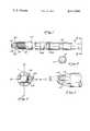
- FIG. 1is a plan view of the orthopedic fixation pin of this invention.
- FIG. 2is an end view taken along lines 2--2 of FIG. 1 showing the proximal or chuck end of the pin.
- FIG. 3is an enlarged side view of the tip of a pin during manufacture before being threaded.
- FIG. 4is an end view showing the tip and transition portions of the unthreaded pin of FIG. 3.
- FIG. 1depicts the overall pin of this invention.
- the pin 10comprises a proximal end on which a drive portion 12, adapted to be fitted into a driving chuck, is formed.
- the driving portion 12, as shown in FIG. 2,is preferably square but, of course, can be any desired configuration, even round, if the chuck is adapted to grasp a round driving portion.
- a groove 14is formed adjacent to proximal end of the pin. This groove is adapted to be received in conventional drilling equipment so as to permit application of withdrawal force, to the right as shown in FIG. 1, by the chuck while rotating the pin.
- a desired number of measuring markers 16a, 16b, and other such markers not shown,may be included. Typically, these measuring markers are spaced at one centimeter intervals along the length of the shaft to permit the surgeon to determine the distance of penetration of the pin.
- the pinitself is simply a longitudinal cylindrical shaft.
- the distal end of the shaft 10is threaded, as shown generally at 18, and includes a transition portion 20 between the shaft portion on which threads 18 are shown and a tip portion 22.
- At least two, and in the preferred embodiment, four flutesare formed in the transition portion and extending into the tip portion and the shaft portion, if desired.
- Each of the flutesis formed by two surfaces shown at 24 and 26. The flutes are symmetrically placed about the center axis of the shaft and form, in the spaces between the flutes, non-fluted surfaces 28.
- the construction of the tip and transition portionsare the significant features of this invention and are best understood by reference to FIGS. 3 and 4, which show a shaft 10 before being threaded, but with the flutes and non-fluted surfaces, as well as a transition portion 20, already formed.
- the transition portion 20is conveniently in the form of a frustocone having a maximum diameter corresponding to the diameter of the shaft and diminishing to the maximum diameter of a tip portion 22 which, in the exemplary embodiment, is in the configuration of a portion of a spherical surface.
- the manufacturing stepsmay be carried out in any number of sequences, it is convenient to consider the configuration of the tip by selecting an arbitrary sequence of steps in the manufacture and considering the structure resulting from each of the steps.
- the following stepsmay be considered as occurring during manufacture.
- onemay form the transition zone 20 simply by forming a frustoconical portion on the end of the shaft. Following manufacture, only a small portion of this frustoconical transition portion remains, as indicated in FIG. 3. It is convenient to consider the next step as forming the intersecting surfaces 24 and 26. Looking at FIG.
- This manufacturing stepis repeated one more time, or two or three more times, depending upon the number of flutes desired.
- four symmetrically spaced flutesare formed. Between each of the flutes there remains a non-fluted surface.
- these non-fluted surfacesare flattened, using any conventional milling device, and so configured as to intersect the surface 24 of the flute, the intersection between the surface 24 and the flattened surface 28 constituting a self-tapping cutting edge for the threads on the pin.
- the surface 28need not be flat and may terminate just short of intersecting with the surface 24 to leave a slight trailing surface behind the cutting edge.
- the tip portion of the pinis formed by simply machining the tip into a partial hemispheric configuration, or any dull configuration. The tip extremity may even be flat. The exact configuration of the tip is not critical, so long as it is not so sharp as to prevent relatively free movement of the pin along the surface of the bone.
- the transition portionis formed in the shape of a frustocone having a frustoconical surface lying at an angle ⁇ which is about eight degrees measured from the longitudinal Z axis of the pin shaft.
- the anglemay vary considerably without departing from the invention, by an angle of about eight to ten degrees has been found quite satisfactory.
- the angleis measured using the axis or the cylindrical surface of the shaft as the reference.
- the surface 28is preferably formed at an angle of about seventy degrees with the plane of the surface 24 which it intersects.
- the angleis, of course, not especially critical as any angle from about twenty to forty degrees could readily be used. An angle of about thirty degrees has been found to be satisfactory where surface 28 intersects surface 24, as measured from the X-axis, best shown in FIG. 4.
- FIG. 3best depicts the relationship of the flutes to the end portion and the transition portion.
- the fluteextends from proximate the distal end of the transition portion, and preferably between the distal end of the transition portion and the tip end of the pin, longitudinally toward the distal end of the pin to about the distal end of the transition portion.
- the flutesdo not extend into the shaft portion of the pin but the flutes could readily be designed to extend into the shaft of the pin without detriment, but also without significant benefit, to the design of the self-tapping screw which results when the shaft is threaded.
- Surgical pinsmay be made in various sizes, depending upon the size of the bone, to which the surgical fixation pin is to be attached, and the strength and rigidity required in a particular application.
- a very useful size of orthopedic fixation pinis described hereafter, but it will be understood that this is simply to exemplify the best embodiment of the invention, and that these dimensions have no particular criticality or significance insofar as the inventive concept is concerned.
- the pin shaftin an exemplary embodiment, is about 0.157 inch, the maximum diameter of the end portion, which is preferably in the form of a sphere, sometimes called the root diameter, is about 0.121 inch, the transition portion extending about 0.09 inch between the maximum diameter of the spherical end portion and the full diameter of the shaft.
- twin lead threadinginvolves two spiral threads superimposed upon one another, the two threads starting on opposite sides of the shaft.
- Twin lead threadsare well-known and standard threading dyes may be used.
- the threadsmay, of course, be cut to any pitch or coarnesness desired, and there is no particular criticality as to the threading utilized.
- the surgical fixation pins describedmay be manufactured of any biologically compatible material which is sufficiently strong and rigid to provide adequate support and sufficiently hard to permit tapping of threads into the bone.
- the pinsare manufactured of titanium alloy containing about ninety percent titanium, six percent aluminum and four percent vanadium.
- the pinsmay also be manufactured from 316 stainless steel.
- any fixation devicesuch as that invented by Dr. Fischer depicted and referred to U.S. patent application Ser. No. 85,996, Filed Oct. 18, 1979, or the conventional Hoffmann fixation device, may be used in conjunction with the surgical pins of this invention.
- a drillbut substantially the same diameter as the root diameter of the pin is used to pre-drill a hole in the bone.
- the drill bit with straight flutehas been found to be superior to conventional spiral flute drill bits, since the spiral flute drill tends to create a butterfly shaped chip on the back of the bone as it emerges.
- any conventional surgical drill bit having a hole diameter approximating the root diameter of the pinmay be used.
- This inventionfinds application in orthopedic surgery in the fixation of broken bones generally, and particularly in the fixation of fractures of the limbs.
Landscapes
- Health & Medical Sciences (AREA)
- Orthopedic Medicine & Surgery (AREA)
- Surgery (AREA)
- Life Sciences & Earth Sciences (AREA)
- Heart & Thoracic Surgery (AREA)
- Nuclear Medicine, Radiotherapy & Molecular Imaging (AREA)
- Engineering & Computer Science (AREA)
- Biomedical Technology (AREA)
- Neurology (AREA)
- Medical Informatics (AREA)
- Molecular Biology (AREA)
- Animal Behavior & Ethology (AREA)
- General Health & Medical Sciences (AREA)
- Public Health (AREA)
- Veterinary Medicine (AREA)
- Surgical Instruments (AREA)
Abstract
Description
Claims (7)
Priority Applications (1)
| Application Number | Priority Date | Filing Date | Title |
|---|---|---|---|
| US06/252,359US4414966A (en) | 1981-04-09 | 1981-04-09 | Fixation pin |
Applications Claiming Priority (1)
| Application Number | Priority Date | Filing Date | Title |
|---|---|---|---|
| US06/252,359US4414966A (en) | 1981-04-09 | 1981-04-09 | Fixation pin |
Publications (1)
| Publication Number | Publication Date |
|---|---|
| US4414966Atrue US4414966A (en) | 1983-11-15 |
Family
ID=22955695
Family Applications (1)
| Application Number | Title | Priority Date | Filing Date |
|---|---|---|---|
| US06/252,359Expired - LifetimeUS4414966A (en) | 1981-04-09 | 1981-04-09 | Fixation pin |
Country Status (1)
| Country | Link |
|---|---|
| US (1) | US4414966A (en) |
Cited By (45)
| Publication number | Priority date | Publication date | Assignee | Title |
|---|---|---|---|---|
| US4537185A (en)* | 1983-06-10 | 1985-08-27 | Denis P. Stednitz | Cannulated fixation screw |
| FR2576774A1 (en)* | 1985-02-07 | 1986-08-08 | Issoire Aviat Sa | Device for three-dimensional positioning of any two pieces, in particular two pieces of bone, and allowing modification of the said positioning |
| US4662365A (en)* | 1982-12-03 | 1987-05-05 | Ortopedia Gmbh | Device for the external fixation of bone fragments |
| EP0230856A1 (en)* | 1985-11-28 | 1987-08-05 | Jaquet Orthopedie S.A. | Transcutaneous fixation pin for fragments or elements of bones |
| JPS62243551A (en)* | 1985-11-28 | 1987-10-24 | ジヤケ・オルトペデイ−・ソシエテ・アノニム | Fixing apuncture pin in external bone connection technique |
| EP0282789A3 (en)* | 1987-03-17 | 1988-10-05 | Hans L. Prof. Grafelmann | Self-tapping bone implant for dentistry |
| EP0323429A1 (en)* | 1987-12-30 | 1989-07-05 | Alain Guinounet | Bone plate locking screw and its fabrication process |
| US4858603A (en)* | 1988-06-06 | 1989-08-22 | Johnson & Johnson Orthopaedics, Inc. | Bone pin |
| US4978350A (en)* | 1986-10-13 | 1990-12-18 | Jaquet Orthopedie S.A. | Transcutaneous pin for fixation of a bone part or fragment |
| US5098435A (en)* | 1990-11-21 | 1992-03-24 | Alphatec Manufacturing Inc. | Cannula |
| US5129901A (en)* | 1991-06-10 | 1992-07-14 | Decoste Vern X | Cannulated orthopedic screw |
| WO1993015681A1 (en)* | 1992-02-06 | 1993-08-19 | Howmedica Inc. | Pin with tapered root diameter |
| EP0574090A1 (en) | 1992-06-12 | 1993-12-15 | Eastman Kodak Company | One equivalent couplers and low pKa release dyes |
| US5456267A (en)* | 1994-03-18 | 1995-10-10 | Stark; John G. | Bone marrow harvesting systems and methods and bone biopsy systems and methods |
| US5522817A (en)* | 1989-03-31 | 1996-06-04 | United States Surgical Corporation | Absorbable surgical fastener with bone penetrating elements |
| US5601559A (en)* | 1988-10-24 | 1997-02-11 | Cook Incorporated | Intraosseous needle |
| US5681352A (en)* | 1996-03-06 | 1997-10-28 | Kinetikos Medical Incorporated | Method and apparatus for anchoring surgical ties to bone |
| US5695336A (en)* | 1992-03-03 | 1997-12-09 | Implant Innovations, Inc. | Dental implant fixture for anchorage in cortical bone |
| US5702346A (en)* | 1992-03-03 | 1997-12-30 | Implant Innovations Inc | Dental implant fixture for anchorage in cortcal bone |
| US5709547A (en)* | 1992-03-03 | 1998-01-20 | Implant Innovations, Inc. | Dental implant for anchorage in cortical bone |
| US5727943A (en)* | 1995-07-18 | 1998-03-17 | Implant Innovations, Inc. | Self-tapping, screw-type dental implant |
| US5902109A (en)* | 1996-01-18 | 1999-05-11 | Implant Innovations, Inc. | Reduced friction screw-type dental implant |
| US6076660A (en)* | 1998-02-05 | 2000-06-20 | Sulzer Calcitek Inc. | Vial for dental implant delivery system |
| US6086371A (en)* | 1998-02-05 | 2000-07-11 | Sulzer Orthopedics Inc. | Dental implant delivery system having driver mount with removable flange |
| US20040199163A1 (en)* | 2003-04-01 | 2004-10-07 | Whittaker Gregory R. | Method and apparatus for fixing a graft in a bone tunnel |
| US20050070907A1 (en)* | 2003-09-25 | 2005-03-31 | Abernathie Dennis L. | Method and device for drilling and tapping a bore for a bone screw |
| US20050165402A1 (en)* | 2002-02-15 | 2005-07-28 | Taras John S. | Cannulated distraction pin for fracture fixation |
| US20050251191A1 (en)* | 2002-05-16 | 2005-11-10 | Scott Taylor | Blunt tip obturator |
| US20080187886A1 (en)* | 2007-02-07 | 2008-08-07 | Robb T Tait | Dental implant with constant thread crest width |
| US7819873B1 (en)* | 2004-09-21 | 2010-10-26 | Biomet Manufacturing Corp. | Method and apparatus for fixation of surgical instruments |
| US20110083294A1 (en)* | 2009-10-11 | 2011-04-14 | Scott Stroup | Self-Cleaning Retractable Putty Knife |
| US20120302838A1 (en)* | 2010-02-12 | 2012-11-29 | Elos Medical Ab | Retractor |
| CN103126761A (en)* | 2013-03-26 | 2013-06-05 | 江苏荷普医疗器械有限公司 | Bone screw |
| US8517977B2 (en) | 2006-10-06 | 2013-08-27 | Applied Medical Resources Corporation | Visual insufflation port |
| US8608769B2 (en) | 2001-09-24 | 2013-12-17 | Applied Medical Resources Corporation | Bladeless optical obturator |
| US8636759B2 (en) | 2001-09-24 | 2014-01-28 | Applied Medical Resources Corporation | Bladeless obturator |
| US8915735B1 (en)* | 1997-11-11 | 2014-12-23 | Nobel Biocare Services Ag | Arrangement for obtaining reliable anchoring of a threaded implant in bone |
| US9060813B1 (en) | 2008-02-29 | 2015-06-23 | Nuvasive, Inc. | Surgical fixation system and related methods |
| US9155558B2 (en) | 2004-06-29 | 2015-10-13 | Applied Medical Resources Corporation | Insufflating optical surgical instrument |
| US9254148B2 (en) | 2011-05-02 | 2016-02-09 | Applied Medical Resources Corporation | Low-profile surgical universal access port |
| US9265899B2 (en) | 2008-01-25 | 2016-02-23 | Applied Medical Resources Corporation | Insufflating access system |
| US9314266B2 (en) | 2008-09-29 | 2016-04-19 | Applied Medical Resources Corporation | First-entry trocar system |
| US9387013B1 (en) | 2011-03-01 | 2016-07-12 | Nuvasive, Inc. | Posterior cervical fixation system |
| CN110831531A (en)* | 2017-04-21 | 2020-02-21 | 德普伊新特斯产品公司 | Angled grooves in cannulated bone screws |
| US11786343B2 (en) | 2020-07-09 | 2023-10-17 | Southern Implants (Pty) Ltd | Dental implants with stepped threads and systems and methods for making the same |
Citations (7)
| Publication number | Priority date | Publication date | Assignee | Title |
|---|---|---|---|---|
| US2388482A (en)* | 1943-01-16 | 1945-11-06 | Herbert H Haynes | Surgical screw |
| US2494229A (en)* | 1946-07-08 | 1950-01-10 | John G Collison | Bone surgery |
| US3623164A (en)* | 1969-10-06 | 1971-11-30 | Gulf Oil Corp | Prosthetic device |
| US3641590A (en)* | 1970-01-16 | 1972-02-15 | Arthur A Michele | Acetabular replacement prosthesis and method of assembling |
| US3741205A (en)* | 1971-06-14 | 1973-06-26 | K Markolf | Bone fixation plate |
| US3987499A (en)* | 1973-08-10 | 1976-10-26 | Sybron Corporation | Surgical implant and method for its production |
| US4312336A (en)* | 1978-11-10 | 1982-01-26 | Orthofix S.R.1. | External axial fixation unit |
- 1981
- 1981-04-09USUS06/252,359patent/US4414966A/ennot_activeExpired - Lifetime
Patent Citations (7)
| Publication number | Priority date | Publication date | Assignee | Title |
|---|---|---|---|---|
| US2388482A (en)* | 1943-01-16 | 1945-11-06 | Herbert H Haynes | Surgical screw |
| US2494229A (en)* | 1946-07-08 | 1950-01-10 | John G Collison | Bone surgery |
| US3623164A (en)* | 1969-10-06 | 1971-11-30 | Gulf Oil Corp | Prosthetic device |
| US3641590A (en)* | 1970-01-16 | 1972-02-15 | Arthur A Michele | Acetabular replacement prosthesis and method of assembling |
| US3741205A (en)* | 1971-06-14 | 1973-06-26 | K Markolf | Bone fixation plate |
| US3987499A (en)* | 1973-08-10 | 1976-10-26 | Sybron Corporation | Surgical implant and method for its production |
| US4312336A (en)* | 1978-11-10 | 1982-01-26 | Orthofix S.R.1. | External axial fixation unit |
Non-Patent Citations (1)
| Title |
|---|
| Machinery's Handbook, 20th Edition, by E. Oberg, F. D. Jones and H. L. Horton, pp. 1684-1699. |
Cited By (74)
| Publication number | Priority date | Publication date | Assignee | Title |
|---|---|---|---|---|
| US4662365A (en)* | 1982-12-03 | 1987-05-05 | Ortopedia Gmbh | Device for the external fixation of bone fragments |
| US4537185A (en)* | 1983-06-10 | 1985-08-27 | Denis P. Stednitz | Cannulated fixation screw |
| FR2576774A1 (en)* | 1985-02-07 | 1986-08-08 | Issoire Aviat Sa | Device for three-dimensional positioning of any two pieces, in particular two pieces of bone, and allowing modification of the said positioning |
| EP0230856A1 (en)* | 1985-11-28 | 1987-08-05 | Jaquet Orthopedie S.A. | Transcutaneous fixation pin for fragments or elements of bones |
| JPS62243551A (en)* | 1985-11-28 | 1987-10-24 | ジヤケ・オルトペデイ−・ソシエテ・アノニム | Fixing apuncture pin in external bone connection technique |
| AU589235B2 (en)* | 1985-11-28 | 1989-10-05 | Jaquet Orthopedie S.A. | Transcutaneous pin for fixation of a bone part of fragment |
| US4978350A (en)* | 1986-10-13 | 1990-12-18 | Jaquet Orthopedie S.A. | Transcutaneous pin for fixation of a bone part or fragment |
| EP0282789A3 (en)* | 1987-03-17 | 1988-10-05 | Hans L. Prof. Grafelmann | Self-tapping bone implant for dentistry |
| EP0323429A1 (en)* | 1987-12-30 | 1989-07-05 | Alain Guinounet | Bone plate locking screw and its fabrication process |
| FR2625430A1 (en)* | 1987-12-30 | 1989-07-07 | Guinounet Alain | LOCKING SCREW OF OSTEOSYNTHESIS PLATE AND METHOD OF MANUFACTURING SAME |
| US4858603A (en)* | 1988-06-06 | 1989-08-22 | Johnson & Johnson Orthopaedics, Inc. | Bone pin |
| US5601559A (en)* | 1988-10-24 | 1997-02-11 | Cook Incorporated | Intraosseous needle |
| US5522817A (en)* | 1989-03-31 | 1996-06-04 | United States Surgical Corporation | Absorbable surgical fastener with bone penetrating elements |
| US5098435A (en)* | 1990-11-21 | 1992-03-24 | Alphatec Manufacturing Inc. | Cannula |
| US5129901A (en)* | 1991-06-10 | 1992-07-14 | Decoste Vern X | Cannulated orthopedic screw |
| WO1993015681A1 (en)* | 1992-02-06 | 1993-08-19 | Howmedica Inc. | Pin with tapered root diameter |
| US5702346A (en)* | 1992-03-03 | 1997-12-30 | Implant Innovations Inc | Dental implant fixture for anchorage in cortcal bone |
| US5695336A (en)* | 1992-03-03 | 1997-12-09 | Implant Innovations, Inc. | Dental implant fixture for anchorage in cortical bone |
| US5709547A (en)* | 1992-03-03 | 1998-01-20 | Implant Innovations, Inc. | Dental implant for anchorage in cortical bone |
| EP0574090A1 (en) | 1992-06-12 | 1993-12-15 | Eastman Kodak Company | One equivalent couplers and low pKa release dyes |
| US5456267A (en)* | 1994-03-18 | 1995-10-10 | Stark; John G. | Bone marrow harvesting systems and methods and bone biopsy systems and methods |
| US5727943A (en)* | 1995-07-18 | 1998-03-17 | Implant Innovations, Inc. | Self-tapping, screw-type dental implant |
| US5902109A (en)* | 1996-01-18 | 1999-05-11 | Implant Innovations, Inc. | Reduced friction screw-type dental implant |
| US6431869B1 (en) | 1996-01-18 | 2002-08-13 | Implant Innovations, Inc. | Reduced friction screw-type dental implant |
| US5681352A (en)* | 1996-03-06 | 1997-10-28 | Kinetikos Medical Incorporated | Method and apparatus for anchoring surgical ties to bone |
| US8915735B1 (en)* | 1997-11-11 | 2014-12-23 | Nobel Biocare Services Ag | Arrangement for obtaining reliable anchoring of a threaded implant in bone |
| US9375295B2 (en) | 1997-11-11 | 2016-06-28 | Nobel Biocare Services Ag | Arrangement for obtaining reliable anchoring of a threaded implant in a bone |
| US6076660A (en)* | 1998-02-05 | 2000-06-20 | Sulzer Calcitek Inc. | Vial for dental implant delivery system |
| US6086371A (en)* | 1998-02-05 | 2000-07-11 | Sulzer Orthopedics Inc. | Dental implant delivery system having driver mount with removable flange |
| US9655643B2 (en) | 2001-09-24 | 2017-05-23 | Applied Medical Resources Corporation | Bladeless optical obturator |
| US10568658B2 (en) | 2001-09-24 | 2020-02-25 | Applied Medical Resources Corporation | Bladeless optical obturator |
| US8608769B2 (en) | 2001-09-24 | 2013-12-17 | Applied Medical Resources Corporation | Bladeless optical obturator |
| US8940009B2 (en) | 2001-09-24 | 2015-01-27 | Applied Medical Resources Corporation | Bladeless optical obturator |
| US8636759B2 (en) | 2001-09-24 | 2014-01-28 | Applied Medical Resources Corporation | Bladeless obturator |
| US9254125B2 (en) | 2001-09-24 | 2016-02-09 | Applied Medical Resources Corporation | Bladeless obturator |
| US20050165402A1 (en)* | 2002-02-15 | 2005-07-28 | Taras John S. | Cannulated distraction pin for fracture fixation |
| US20050251191A1 (en)* | 2002-05-16 | 2005-11-10 | Scott Taylor | Blunt tip obturator |
| US8377090B2 (en) | 2002-05-16 | 2013-02-19 | Applied Medical Resources Corporation | Blunt tip obturator |
| US9545248B2 (en) | 2002-05-16 | 2017-01-17 | Applied Medical Resources Corporation | Blunt tip obturator |
| US7758603B2 (en)* | 2002-05-16 | 2010-07-20 | Applied Medical Resources Corporation | Blunt tip obturator |
| US11207098B2 (en) | 2002-05-16 | 2021-12-28 | Applied Medical Resources Corporation | Blunt tip obturator |
| US8608768B2 (en) | 2002-05-16 | 2013-12-17 | Applied Medical Resources Corporation | Blunt tip obturator |
| US10368906B2 (en) | 2002-05-16 | 2019-08-06 | Applied Medical Resources Corporation | Blunt tip obturator |
| US8080058B2 (en)* | 2003-04-01 | 2011-12-20 | Depuy Mitek, Inc. | Method and apparatus for fixing a graft in a bone tunnel |
| US20040199163A1 (en)* | 2003-04-01 | 2004-10-07 | Whittaker Gregory R. | Method and apparatus for fixing a graft in a bone tunnel |
| US20050070907A1 (en)* | 2003-09-25 | 2005-03-31 | Abernathie Dennis L. | Method and device for drilling and tapping a bore for a bone screw |
| US10226589B2 (en) | 2003-10-03 | 2019-03-12 | Applied Medical Resources Corporation | Insufflating optical surgical instrument |
| US10918814B2 (en) | 2003-10-03 | 2021-02-16 | Applied Medical Resources Corporation | Insufflating optical surgical instrument |
| US9155558B2 (en) | 2004-06-29 | 2015-10-13 | Applied Medical Resources Corporation | Insufflating optical surgical instrument |
| US7819873B1 (en)* | 2004-09-21 | 2010-10-26 | Biomet Manufacturing Corp. | Method and apparatus for fixation of surgical instruments |
| US11123105B2 (en) | 2006-10-06 | 2021-09-21 | Applied Medical Resources Corporation | Visual insufflation port |
| US9492062B2 (en) | 2006-10-06 | 2016-11-15 | Applied Medical Resources Corporation | Visual insufflation port |
| US8517977B2 (en) | 2006-10-06 | 2013-08-27 | Applied Medical Resources Corporation | Visual insufflation port |
| US20080187886A1 (en)* | 2007-02-07 | 2008-08-07 | Robb T Tait | Dental implant with constant thread crest width |
| US9265899B2 (en) | 2008-01-25 | 2016-02-23 | Applied Medical Resources Corporation | Insufflating access system |
| US9060813B1 (en) | 2008-02-29 | 2015-06-23 | Nuvasive, Inc. | Surgical fixation system and related methods |
| US10022150B2 (en) | 2008-09-29 | 2018-07-17 | Applied Medical Resources Corporation | First-entry trocar system |
| US11723689B2 (en) | 2008-09-29 | 2023-08-15 | Applied Medical Resources Corporation | First-entry trocar system |
| US9358040B2 (en) | 2008-09-29 | 2016-06-07 | Applied Medical Resources Corporation | First-entry trocar system |
| US9314266B2 (en) | 2008-09-29 | 2016-04-19 | Applied Medical Resources Corporation | First-entry trocar system |
| US10856906B2 (en) | 2008-09-29 | 2020-12-08 | Applied Medical Resources Corporation | First-entry trocar system |
| US20110083294A1 (en)* | 2009-10-11 | 2011-04-14 | Scott Stroup | Self-Cleaning Retractable Putty Knife |
| US8584302B2 (en) | 2009-10-11 | 2013-11-19 | Scott Stroup | Self-cleaning retractable putty knife |
| US9414826B2 (en)* | 2010-02-12 | 2016-08-16 | Elos Medtech Timmersdala Ab | Retractor |
| US20120302838A1 (en)* | 2010-02-12 | 2012-11-29 | Elos Medical Ab | Retractor |
| US11123110B2 (en) | 2011-03-01 | 2021-09-21 | Nuvasive, Inc. | Posterior cervical fixation system |
| US10368918B2 (en) | 2011-03-01 | 2019-08-06 | Nuvasive, Inc. | Posterior cervical fixation system |
| US9387013B1 (en) | 2011-03-01 | 2016-07-12 | Nuvasive, Inc. | Posterior cervical fixation system |
| US9956009B1 (en) | 2011-03-01 | 2018-05-01 | Nuvasive, Inc. | Posterior cervical fixation system |
| US9254148B2 (en) | 2011-05-02 | 2016-02-09 | Applied Medical Resources Corporation | Low-profile surgical universal access port |
| CN103126761A (en)* | 2013-03-26 | 2013-06-05 | 江苏荷普医疗器械有限公司 | Bone screw |
| CN110831531A (en)* | 2017-04-21 | 2020-02-21 | 德普伊新特斯产品公司 | Angled grooves in cannulated bone screws |
| US11751926B2 (en) | 2017-04-21 | 2023-09-12 | DePuy Synthes Products, Inc. | Angled flutes in cannulated bone screws |
| US11786343B2 (en) | 2020-07-09 | 2023-10-17 | Southern Implants (Pty) Ltd | Dental implants with stepped threads and systems and methods for making the same |
Similar Documents
| Publication | Publication Date | Title |
|---|---|---|
| US4414966A (en) | Fixation pin | |
| US4537185A (en) | Cannulated fixation screw | |
| US20210307800A1 (en) | Angled Flutes in Cannulated Bone Screws | |
| US4538989A (en) | Dental reamer | |
| US5797914A (en) | Bone screw | |
| JP6419733B2 (en) | Universal screw design and cutting tool | |
| US6030162A (en) | Axial tension screw | |
| CA2494062C (en) | A drill bit and method for producing a drill bit | |
| US4373518A (en) | Method of drilling living bone | |
| CA2817079C (en) | Orthopaedic drill bit | |
| US20120130433A1 (en) | Axial tension screw | |
| FI92975B (en) | Transcutaneous needle for fixing leg parts | |
| CN211094600U (en) | Self-tapping bone screw and fracture fixation system | |
| CA1329081C (en) | Transcutaneous pin for fixation of a bone part or fragment | |
| US20070083206A1 (en) | Self drilling and tapping bone screw | |
| JP2019126651A (en) | Bone treatment implement, screw for bone, and plate for bone | |
| JP3323747B2 (en) | Orthopedic tap | |
| CN217040267U (en) | Bone screw and coaptation device | |
| CN112156357A (en) | Skull screw | |
| CN223054508U (en) | Medical drill bit structure and drilling device | |
| US20240164819A1 (en) | Orthopedic Bone Screw | |
| BR112020008780B1 (en) | BONE CAGE |
Legal Events
| Date | Code | Title | Description |
|---|---|---|---|
| AS | Assignment | Owner name:ACE ORTHOPEDIC MANUFACTURING, INC., Free format text:ASSIGNMENT OF ASSIGNORS INTEREST.;ASSIGNOR:STEDNITZ DENIS P.;REEL/FRAME:003878/0523 Effective date:19810317 Owner name:ACE ORTHOPEDIC MANUFACTURING, INC., STATELESS Free format text:ASSIGNMENT OF ASSIGNORS INTEREST;ASSIGNOR:STEDNITZ DENIS P.;REEL/FRAME:003878/0523 Effective date:19810317 | |
| STCF | Information on status: patent grant | Free format text:PATENTED CASE | |
| FEPP | Fee payment procedure | Free format text:MAINTENANCE FEE REMINDER MAILED (ORIGINAL EVENT CODE: REM.); ENTITY STATUS OF PATENT OWNER: LARGE ENTITY | |
| FEPP | Fee payment procedure | Free format text:SURCHARGE FOR LATE PAYMENT, PL 96-517 (ORIGINAL EVENT CODE: M176); ENTITY STATUS OF PATENT OWNER: LARGE ENTITY | |
| MAFP | Maintenance fee payment | Free format text:PAYMENT OF MAINTENANCE FEE, 4TH YEAR, PL 96-517 (ORIGINAL EVENT CODE: M170); ENTITY STATUS OF PATENT OWNER: LARGE ENTITY Year of fee payment:4 | |
| MAFP | Maintenance fee payment | Free format text:PAYMENT OF MAINTENANCE FEE, 8TH YEAR, PL 96-517 (ORIGINAL EVENT CODE: M171); ENTITY STATUS OF PATENT OWNER: LARGE ENTITY Year of fee payment:8 | |
| FEPP | Fee payment procedure | Free format text:PAYOR NUMBER ASSIGNED (ORIGINAL EVENT CODE: ASPN); ENTITY STATUS OF PATENT OWNER: LARGE ENTITY | |
| MAFP | Maintenance fee payment | Free format text:PAYMENT OF MAINTENANCE FEE, 12TH YR, SMALL ENTITY (ORIGINAL EVENT CODE: M285); ENTITY STATUS OF PATENT OWNER: LARGE ENTITY Year of fee payment:12 | |
| FEPP | Fee payment procedure | Free format text:PAT HLDR NO LONGER CLAIMS SMALL ENT STAT AS SMALL BUSINESS (ORIGINAL EVENT CODE: LSM2); ENTITY STATUS OF PATENT OWNER: LARGE ENTITY | |
| AS | Assignment | Owner name:DEPUY ACE MEDICAL COMPANY, CALIFORNIA Free format text:CHANGE OF NAME;ASSIGNOR:ACE MEDICAL COMPANY;REEL/FRAME:009693/0160 Effective date:19960814 Owner name:ACE MEDICAL COMPANY, CALIFORNIA Free format text:MERGER;ASSIGNOR:ACE ORTHOPEDIC MANUFACTURING, INC.;REEL/FRAME:009689/0964 Effective date:19921222 |