US4414858A - Steam turbine fluid sampling apparatus - Google Patents
Steam turbine fluid sampling apparatusDownload PDFInfo
- Publication number
- US4414858A US4414858AUS06/360,739US36073982AUS4414858AUS 4414858 AUS4414858 AUS 4414858AUS 36073982 AUS36073982 AUS 36073982AUS 4414858 AUS4414858 AUS 4414858A
- Authority
- US
- United States
- Prior art keywords
- fluid
- steam turbine
- steam
- turbine system
- fluid sample
- Prior art date
- Legal status (The legal status is an assumption and is not a legal conclusion. Google has not performed a legal analysis and makes no representation as to the accuracy of the status listed.)
- Expired - Fee Related
Links
Images

Classifications
- G—PHYSICS
- G01—MEASURING; TESTING
- G01N—INVESTIGATING OR ANALYSING MATERIALS BY DETERMINING THEIR CHEMICAL OR PHYSICAL PROPERTIES
- G01N1/00—Sampling; Preparing specimens for investigation
- G01N1/02—Devices for withdrawing samples
- G01N1/10—Devices for withdrawing samples in the liquid or fluent state
- G—PHYSICS
- G01—MEASURING; TESTING
- G01N—INVESTIGATING OR ANALYSING MATERIALS BY DETERMINING THEIR CHEMICAL OR PHYSICAL PROPERTIES
- G01N1/00—Sampling; Preparing specimens for investigation
- G01N1/02—Devices for withdrawing samples
- G01N1/22—Devices for withdrawing samples in the gaseous state
- G01N1/26—Devices for withdrawing samples in the gaseous state with provision for intake from several spaces
- Y—GENERAL TAGGING OF NEW TECHNOLOGICAL DEVELOPMENTS; GENERAL TAGGING OF CROSS-SECTIONAL TECHNOLOGIES SPANNING OVER SEVERAL SECTIONS OF THE IPC; TECHNICAL SUBJECTS COVERED BY FORMER USPC CROSS-REFERENCE ART COLLECTIONS [XRACs] AND DIGESTS
- Y10—TECHNICAL SUBJECTS COVERED BY FORMER USPC
- Y10T—TECHNICAL SUBJECTS COVERED BY FORMER US CLASSIFICATION
- Y10T137/00—Fluid handling
- Y10T137/8158—With indicator, register, recorder, alarm or inspection means
- Y10T137/8175—Plural
- Y10T137/8192—Unobvious - "combination lock" type
- Y—GENERAL TAGGING OF NEW TECHNOLOGICAL DEVELOPMENTS; GENERAL TAGGING OF CROSS-SECTIONAL TECHNOLOGIES SPANNING OVER SEVERAL SECTIONS OF THE IPC; TECHNICAL SUBJECTS COVERED BY FORMER USPC CROSS-REFERENCE ART COLLECTIONS [XRACs] AND DIGESTS
- Y10—TECHNICAL SUBJECTS COVERED BY FORMER USPC
- Y10T—TECHNICAL SUBJECTS COVERED BY FORMER US CLASSIFICATION
- Y10T137/00—Fluid handling
- Y10T137/8593—Systems
- Y10T137/87249—Multiple inlet with multiple outlet
- Y—GENERAL TAGGING OF NEW TECHNOLOGICAL DEVELOPMENTS; GENERAL TAGGING OF CROSS-SECTIONAL TECHNOLOGIES SPANNING OVER SEVERAL SECTIONS OF THE IPC; TECHNICAL SUBJECTS COVERED BY FORMER USPC CROSS-REFERENCE ART COLLECTIONS [XRACs] AND DIGESTS
- Y10—TECHNICAL SUBJECTS COVERED BY FORMER USPC
- Y10T—TECHNICAL SUBJECTS COVERED BY FORMER US CLASSIFICATION
- Y10T137/00—Fluid handling
- Y10T137/8593—Systems
- Y10T137/87571—Multiple inlet with single outlet
- Y10T137/87676—With flow control
- Y10T137/87684—Valve in each inlet
- Y10T137/87692—With common valve operator
Definitions
- the inventionin general relates to multi-point sampling systems, and particularly to an arrangement which automatically samples and analyzes water and steam condensate from a plurality of points in a steam turbine system.
- the present inventionprovides for the automatic collecting of representative samples of high purity water or steam condensate from various points in the steam turbine system.
- Apparatus for sampling fluids in a steam turbine system in accordance with the present inventionincludes a valve arrangement which has a plurality of valves each of which may be activated in response to an applied control signal.
- a plurality of fluid sample linesis connected between various points in the steam turbine system and the valve arrangement.
- An analyzeris provided for analyzing selected fluid samples passed by the valving arrangement and all of those samples which are not selected are continuously flowing to a common drain line which is connected back to steam turbine fluid system so as to minimize loss of high purity water.
- a computersuch as a microprocessor supplies the control signals to activated selected ones of the valves in accordance with a set of stored instructions so as to place a single one of the fluid sample lines in fluid communication with the analyzer.
- Each fluid sample lineincludes a sensor providing an output signal to the computer whereby the sampling pattern of the fluid sample lines may be altered if the particular sensor output indicates an alarm condition.
- the computermay alter the sampling sequence in response to the analyzer output if such output indicates the necessity for such alteration.
- FIG. 1illustrates a simplified diagram of a steam turbine-generator power plant
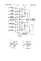
- FIG. 2is a block diagram illustrating one embodiment of the present invention.
- FIGS. 3A and 3Billustrate the fluid flow through a typical valve of FIG. 2.
- FIG. 1illustrates a typical steam turbine system for a power plant and includes a steam turbine arrangement 10 having a plurality of turbines in the form of high pressure turbine 12, intermediate pressure turbine 14 and low pressure turbine 16, all of which are coupled to a common shaft 18 to drive an electrical generator 20 which supplies power to a load 22.
- a steam turbine arrangement 10having a plurality of turbines in the form of high pressure turbine 12, intermediate pressure turbine 14 and low pressure turbine 16, all of which are coupled to a common shaft 18 to drive an electrical generator 20 which supplies power to a load 22.
- a steam supply in the form of a boiler system 24includes, by way of example, an input economizer section 26 and a reheater section 28.
- Boiler steamis provided to the turbine arrangement 10 through input valving 30 and steam exiting the high pressure turbine 12 is reheated in reheater section 28 and provided to intermediate pressure turbine 14 through valving 32.
- Steam exiting the intermediate pressure turbine 14is provided by way of crossover piping 34 to the low pressure turbine 16 from which the steam is exhausted into a conventional condenser 36.
- the chemical treatmentmay include a plurality of polishers 40 which basically are ion exchange units designed to remove impurities. After the chemical treatment the water is heated by a series of heaters 42 and returned to the input economizer 26 of the boiler system 24.
- a sampling system 50is provided and in accordance with the present invention automatically obtains samples from various points in the steam turbine system.
- fluid sample line 52samples condensate fluid from condenser 36.
- Fluid sample lines 53-55are connected to sample effluent from respective first, second and third polishers while line 56 samples the combined polisher effluent.
- Line 57is connected to sample the input to the economizer 26, line 58 samples the main steam output and line 59 is cnnected to sample the hot reheat steam.
- a plurality of preconditionersare provided to reduce temperatures and pressures of the circulating fluid to manageable values.
- lines 57-59contain respective preconditioners 62-64 so as to reduce the temperature and pressure of fluid at the input to the economizer, output of the boiler system, and output of the reheater, respectively.
- the sampling system 50will communicate one of the fluid sample lines to analyzing equipment 68 and will communicate all the non-selected lines to a common drain line 70 connected to supply the fluid in the fluid sample lines back to the recirculating fluid of the steam turbine system.
- common drain line 70may be connected directly to condenser 36.
- the sampling system 50is illustrated in more detail in FIG. 2 and includes a valve arrangement 80 having a plurality of valves V1-V7 each of which governs fluid flow therethrough in response to an applied control signal.
- a control 82in the form of a digital computer having a set of stored instructions for generating output control signals applied to the individual valves by means of control lines 84.
- FIGS. 3A and 3Billustrate the fluid flow through a typical valve which may be utilized herein.
- block 86represents the valve body
- lines 88 and 89are input lines to the valve
- lines 90 and 91are output lines therefrom.
- Arrows 92 and 93represent the fluid flow through the valve body.
- Computer 82may provide a logical ZERO to selected one of the valves in which case it will assume a fluid flow orientation as in FIG. 3A whereas the provision of a logical ONE from the computer will cause a valve to assume a fluid flow condition as in FIG. 3B. Therefore, to communicate an individual one of the fluid sample lines to the analyzer while communicating the remainder to the common drain line, control signals may be provided in accordance with Table I.
- each linemay have its own individual valve for communicating that line directly with the analyzer, with the valve being of the type wherein there is continuous fluid flow either to the analyzer, when that line is selected by computer 82, or to the common drain line 70.
- the continuous flow featureany particular fluid sample is immediately ready for analysis whereas if the lines were dead ended, that is, connected to a valve which is either fully opened or fully closed, then a great deal of time would be wasted for a sample to be equilibrated. For ultra-high purity water samples as found in the steam turbine environment, this equilibration time may be as high as 24 hours.
- analyzer 68will perform its analysis function as dictated by the computer via link 96. Once the results of the analysis have been obtained the computer will select the next sample line in accordance with its stored instructions or alternatively will examine another sample, out of its normal sequence, in accordance with the results of the analysis as provided to the computer via link 96.
- the apparatus of the present inventionis additionally designed and constructed to interrupt the predetermined schedule of sampling in response to abnormal conditions in the fluid sample lines. More particularly, a plurality of sensors S1-S8 are provided for respective fluid sample lines 52-59 and are designed to measure some predetermined parameter of the fluid in the fluid sample line.
- sensorsmay be conductivity meters which supply respective output signals via signal lines 98 to the computer 82 which functions to continuously scan the sensor outputs, compare each with predetermined stored limits and in the absence of an alarm condition (a reading out of normal limits) the computer will sample each line according to its programmed instructions. When one or more lines reach alarm levels the normal analysis sequence will be interrupted to service the alarm sample. In the case of several alarms a priority basis is utilized for the sampling.
Landscapes
- Life Sciences & Earth Sciences (AREA)
- Health & Medical Sciences (AREA)
- General Health & Medical Sciences (AREA)
- Physics & Mathematics (AREA)
- Chemical & Material Sciences (AREA)
- Analytical Chemistry (AREA)
- Biochemistry (AREA)
- General Physics & Mathematics (AREA)
- Immunology (AREA)
- Pathology (AREA)
- Biomedical Technology (AREA)
- Molecular Biology (AREA)
- Engineering & Computer Science (AREA)
- Hydrology & Water Resources (AREA)
- Sampling And Sample Adjustment (AREA)
Abstract
Description
TABLE I ______________________________________ Select Control Signals to Valves Line V1 V2 V3 V4 V5 V6 V7 ______________________________________ 52 1 * * * 1 * 1 53 0 * * * 1 * 1 54 * 1 * * 0 * 1 55 * 0 * * 0 * 1 56 * * 1 * * 1 0 57 * * 0 * * 1 0 58 * * * 1 * 0 0 59 * * * 0 * 0 0 ______________________________________ *can be either 1 or 0
Claims (7)
Priority Applications (2)
| Application Number | Priority Date | Filing Date | Title |
|---|---|---|---|
| US06/360,739US4414858A (en) | 1982-03-22 | 1982-03-22 | Steam turbine fluid sampling apparatus |
| JP58046106AJPS58172534A (en) | 1982-03-22 | 1983-03-22 | Sampling device for fluid of steam turbine system |
Applications Claiming Priority (1)
| Application Number | Priority Date | Filing Date | Title |
|---|---|---|---|
| US06/360,739US4414858A (en) | 1982-03-22 | 1982-03-22 | Steam turbine fluid sampling apparatus |
Publications (1)
| Publication Number | Publication Date |
|---|---|
| US4414858Atrue US4414858A (en) | 1983-11-15 |
Family
ID=23419220
Family Applications (1)
| Application Number | Title | Priority Date | Filing Date |
|---|---|---|---|
| US06/360,739Expired - Fee RelatedUS4414858A (en) | 1982-03-22 | 1982-03-22 | Steam turbine fluid sampling apparatus |
Country Status (2)
| Country | Link |
|---|---|
| US (1) | US4414858A (en) |
| JP (1) | JPS58172534A (en) |
Cited By (14)
| Publication number | Priority date | Publication date | Assignee | Title |
|---|---|---|---|---|
| US4713772A (en)* | 1985-11-18 | 1987-12-15 | Westinghouse Electric Corp. | Automatic on-line chemistry monitoring system having improved calibration unit |
| US4713618A (en)* | 1985-10-02 | 1987-12-15 | Westinghouse Electric Corp. | On-line calibration system for chemical monitors |
| US4766550A (en)* | 1985-10-30 | 1988-08-23 | Westinghouse Electric Corp. | Automatic on-line chemistry monitoring system |
| US4882122A (en)* | 1988-02-10 | 1989-11-21 | General Electric Company | Method and apparatus for obtaining a water sample from the core of a boiling water reactor |
| EP0338279A3 (en)* | 1988-04-15 | 1990-08-22 | Westinghouse Electric Corporation | Chemistry monitor system |
| US5005430A (en)* | 1989-05-16 | 1991-04-09 | Electric Power Research Institute, Inc. | Automated membrane filter sampler |
| US5331840A (en)* | 1990-02-08 | 1994-07-26 | Sentech Corporation | Detection of a gas leaked into a liquid which has been sampled from a plurality of spaces |
| US5357781A (en)* | 1993-01-22 | 1994-10-25 | Sentech Corporation | Method and apparatus for sampling and detecting gases in a fluid |
| WO1999032873A1 (en)* | 1997-12-22 | 1999-07-01 | Ufz-Umweltforschungszentrum Leipzig-Halle Gmbh | Multichannel sample-taking and measuring system for automatic long-term analysis of fluids |
| US6125710A (en)* | 1997-04-15 | 2000-10-03 | Phoenix Controls Corporation | Networked air measurement system |
| US6241950B1 (en)* | 1998-02-13 | 2001-06-05 | Airxpert Systems, Inc. | Fluid sampling system |
| US20060042701A1 (en)* | 2004-08-25 | 2006-03-02 | Jansen's Aircraft Systems Controls, Inc. | Emissions sampling valve |
| US9719891B2 (en) | 2015-05-13 | 2017-08-01 | The Southern Company | Simultaneous multi-point testing systems and methods |
| CN108604307A (en)* | 2016-02-12 | 2018-09-28 | 开利公司 | The self-adapted sensor of cold chain distribution system samples |
Families Citing this family (1)
| Publication number | Priority date | Publication date | Assignee | Title |
|---|---|---|---|---|
| JP4867750B2 (en)* | 2007-03-28 | 2012-02-01 | 栗田工業株式会社 | How to monitor steam path corrosion |
Citations (11)
| Publication number | Priority date | Publication date | Assignee | Title |
|---|---|---|---|---|
| US2595311A (en)* | 1947-06-05 | 1952-05-06 | Mine Safety Appliances Co | Automatic multiple sampling valve |
| US2721578A (en)* | 1950-12-26 | 1955-10-25 | Phillips Petroleum Co | Multistream rotary selector valve |
| US2736201A (en)* | 1956-02-28 | Automatic metering and sampling station | ||
| US2840109A (en)* | 1957-02-25 | 1958-06-24 | Win Well Mfg Company | Rotary selector valve |
| US3043145A (en)* | 1958-06-10 | 1962-07-10 | Bailey Meter Co | Gas sample scanning apparatus |
| US3607073A (en)* | 1968-07-22 | 1971-09-21 | Texaco Inc | Method and apparatus for analysis of fluid mixtures |
| US3757583A (en)* | 1971-02-08 | 1973-09-11 | Environment One Corp | Fluid sampling valve |
| US3846075A (en)* | 1972-09-25 | 1974-11-05 | Squibb & Sons Inc | Apparatus for simultaneous analysis of fluid |
| US3921456A (en)* | 1974-01-14 | 1975-11-25 | Environmental Measurements Inc | Air quality sampler |
| US3927670A (en)* | 1973-01-05 | 1975-12-23 | Stephen Z Turney | Automatic respiratory gas monitoring system |
| US4090392A (en)* | 1977-08-01 | 1978-05-23 | Ethyl Corporation | Automatic gas analyzer system |
- 1982
- 1982-03-22USUS06/360,739patent/US4414858A/ennot_activeExpired - Fee Related
- 1983
- 1983-03-22JPJP58046106Apatent/JPS58172534A/enactiveGranted
Patent Citations (11)
| Publication number | Priority date | Publication date | Assignee | Title |
|---|---|---|---|---|
| US2736201A (en)* | 1956-02-28 | Automatic metering and sampling station | ||
| US2595311A (en)* | 1947-06-05 | 1952-05-06 | Mine Safety Appliances Co | Automatic multiple sampling valve |
| US2721578A (en)* | 1950-12-26 | 1955-10-25 | Phillips Petroleum Co | Multistream rotary selector valve |
| US2840109A (en)* | 1957-02-25 | 1958-06-24 | Win Well Mfg Company | Rotary selector valve |
| US3043145A (en)* | 1958-06-10 | 1962-07-10 | Bailey Meter Co | Gas sample scanning apparatus |
| US3607073A (en)* | 1968-07-22 | 1971-09-21 | Texaco Inc | Method and apparatus for analysis of fluid mixtures |
| US3757583A (en)* | 1971-02-08 | 1973-09-11 | Environment One Corp | Fluid sampling valve |
| US3846075A (en)* | 1972-09-25 | 1974-11-05 | Squibb & Sons Inc | Apparatus for simultaneous analysis of fluid |
| US3927670A (en)* | 1973-01-05 | 1975-12-23 | Stephen Z Turney | Automatic respiratory gas monitoring system |
| US3921456A (en)* | 1974-01-14 | 1975-11-25 | Environmental Measurements Inc | Air quality sampler |
| US4090392A (en)* | 1977-08-01 | 1978-05-23 | Ethyl Corporation | Automatic gas analyzer system |
Cited By (18)
| Publication number | Priority date | Publication date | Assignee | Title |
|---|---|---|---|---|
| US4713618A (en)* | 1985-10-02 | 1987-12-15 | Westinghouse Electric Corp. | On-line calibration system for chemical monitors |
| US4766550A (en)* | 1985-10-30 | 1988-08-23 | Westinghouse Electric Corp. | Automatic on-line chemistry monitoring system |
| EP0220666A3 (en)* | 1985-10-30 | 1989-03-15 | Westinghouse Electric Corporation | Automatic on-line chemistry monitoring system |
| US4713772A (en)* | 1985-11-18 | 1987-12-15 | Westinghouse Electric Corp. | Automatic on-line chemistry monitoring system having improved calibration unit |
| US4882122A (en)* | 1988-02-10 | 1989-11-21 | General Electric Company | Method and apparatus for obtaining a water sample from the core of a boiling water reactor |
| EP0338279A3 (en)* | 1988-04-15 | 1990-08-22 | Westinghouse Electric Corporation | Chemistry monitor system |
| US5073499A (en)* | 1988-04-15 | 1991-12-17 | Westinghouse Electric Corp. | Chemical diagnostic system |
| US5005430A (en)* | 1989-05-16 | 1991-04-09 | Electric Power Research Institute, Inc. | Automated membrane filter sampler |
| US5331840A (en)* | 1990-02-08 | 1994-07-26 | Sentech Corporation | Detection of a gas leaked into a liquid which has been sampled from a plurality of spaces |
| US5357781A (en)* | 1993-01-22 | 1994-10-25 | Sentech Corporation | Method and apparatus for sampling and detecting gases in a fluid |
| US6125710A (en)* | 1997-04-15 | 2000-10-03 | Phoenix Controls Corporation | Networked air measurement system |
| US6425297B1 (en) | 1997-04-15 | 2002-07-30 | Aircuity, Inc. | Networked air measurement system |
| WO1999032873A1 (en)* | 1997-12-22 | 1999-07-01 | Ufz-Umweltforschungszentrum Leipzig-Halle Gmbh | Multichannel sample-taking and measuring system for automatic long-term analysis of fluids |
| US6241950B1 (en)* | 1998-02-13 | 2001-06-05 | Airxpert Systems, Inc. | Fluid sampling system |
| US20060042701A1 (en)* | 2004-08-25 | 2006-03-02 | Jansen's Aircraft Systems Controls, Inc. | Emissions sampling valve |
| US7340939B2 (en)* | 2004-08-25 | 2008-03-11 | Jansen's Aircraft Systems Controls, Inc. | Emissions sampling valve |
| US9719891B2 (en) | 2015-05-13 | 2017-08-01 | The Southern Company | Simultaneous multi-point testing systems and methods |
| CN108604307A (en)* | 2016-02-12 | 2018-09-28 | 开利公司 | The self-adapted sensor of cold chain distribution system samples |
Also Published As
| Publication number | Publication date |
|---|---|
| JPS6116926B2 (en) | 1986-05-02 |
| JPS58172534A (en) | 1983-10-11 |
Similar Documents
| Publication | Publication Date | Title |
|---|---|---|
| US4414858A (en) | Steam turbine fluid sampling apparatus | |
| CA1123080A (en) | Electronic drain system | |
| KR860000851A (en) | Diagnostic device | |
| US5249260A (en) | Data input system | |
| SE1950856A1 (en) | Method and controller for dynamically determining a system curve in a heat power system | |
| US4386498A (en) | Method and apparatus for preventing the deposition of corrosive salts on rotor blades of steam turbines | |
| GB1560523A (en) | System to control low pressure turbine temperature | |
| US4274259A (en) | Superheated steam power plant with steam to steam reheater | |
| CN110056849B (en) | Water supply method for waste heat recovery boiler and waste heat recovery boiler | |
| JPH10169406A (en) | Sampling device | |
| US3180798A (en) | Vapor cooled nuclear reactor | |
| JPS56141008A (en) | Performance supervisory method for steam power plant | |
| JPS59219603A (en) | Reheating boiler for factory | |
| US3070962A (en) | Steam seal diverting valve | |
| KR830001118B1 (en) | Automatic drainage method | |
| Pickhardt et al. | An indirect adaptive predictive controller for linear and nonlinear plants | |
| SU1100412A1 (en) | Device for regulating heat load of extraction steam turbine | |
| JP3638307B2 (en) | Reheat steam pipe device for nuclear power plant | |
| SU1442532A1 (en) | Apparatus for automatic control of process duty of coke dry quenching plant | |
| SU1430562A1 (en) | Method of operation of extraction steam turbine plant | |
| Sopocy et al. | EPRI Interim Consensus guidelines on fossil plant cycle Chemistry | |
| Darwish et al. | The Kuwait university pilot plant: a single multi-effect plant to study the variation of evaporation parameters at different temperatures | |
| JPH01124007A (en) | Plant operation status evaluation method | |
| Song et al. | Fault diagnosis method using network and fuzziness | |
| KR20230069191A (en) | Steam generator with desuperheater |
Legal Events
| Date | Code | Title | Description |
|---|---|---|---|
| AS | Assignment | Owner name:WESTINGHOUSE ELECTRIC CORPORATION, WESTINGHOUSE BL Free format text:ASSIGNMENT OF ASSIGNORS INTEREST.;ASSIGNORS:PETERSON, STEVEN H.;PENSENSTADLER, DAVID F.;REEL/FRAME:003993/0499 Effective date:19820318 Owner name:WESTINGHOUSE ELECTRIC CORPORATION,PENNSYLVANIA Free format text:ASSIGNMENT OF ASSIGNORS INTEREST;ASSIGNORS:PETERSON, STEVEN H.;PENSENSTADLER, DAVID F.;REEL/FRAME:003993/0499 Effective date:19820318 | |
| MAFP | Maintenance fee payment | Free format text:PAYMENT OF MAINTENANCE FEE, 4TH YEAR, PL 96-517 (ORIGINAL EVENT CODE: M170); ENTITY STATUS OF PATENT OWNER: LARGE ENTITY Year of fee payment:4 | |
| MAFP | Maintenance fee payment | Free format text:PAYMENT OF MAINTENANCE FEE, 8TH YEAR, PL 96-517 (ORIGINAL EVENT CODE: M171); ENTITY STATUS OF PATENT OWNER: LARGE ENTITY Year of fee payment:8 | |
| FEPP | Fee payment procedure | Free format text:MAINTENANCE FEE REMINDER MAILED (ORIGINAL EVENT CODE: REM.); ENTITY STATUS OF PATENT OWNER: LARGE ENTITY | |
| LAPS | Lapse for failure to pay maintenance fees | ||
| FP | Lapsed due to failure to pay maintenance fee | Effective date:19961115 | |
| STCH | Information on status: patent discontinuation | Free format text:PATENT EXPIRED DUE TO NONPAYMENT OF MAINTENANCE FEES UNDER 37 CFR 1.362 |