US4413514A - Air flow sensor - Google Patents
Air flow sensorDownload PDFInfo
- Publication number
- US4413514A US4413514AUS06/266,487US26648781AUS4413514AUS 4413514 AUS4413514 AUS 4413514AUS 26648781 AUS26648781 AUS 26648781AUS 4413514 AUS4413514 AUS 4413514A
- Authority
- US
- United States
- Prior art keywords
- thermistor
- housing
- voltage
- temperature
- current
- Prior art date
- Legal status (The legal status is an assumption and is not a legal conclusion. Google has not performed a legal analysis and makes no representation as to the accuracy of the status listed.)
- Expired - Fee Related
Links
- 239000012530fluidSubstances0.000claimsabstractdescription27
- 230000008859changeEffects0.000claimsdescription5
- 238000000034methodMethods0.000claimsdescription5
- 230000003247decreasing effectEffects0.000claimsdescription4
- 238000010438heat treatmentMethods0.000claimsdescription4
- 239000012080ambient airSubstances0.000abstractdescription9
- 239000003570airSubstances0.000description39
- 230000007423decreaseEffects0.000description16
- 239000000523sampleSubstances0.000description12
- 238000001514detection methodMethods0.000description7
- 238000010586diagramMethods0.000description6
- 239000007858starting materialSubstances0.000description5
- 230000015556catabolic processEffects0.000description4
- 230000000694effectsEffects0.000description3
- 238000004378air conditioningMethods0.000description2
- 238000001816coolingMethods0.000description2
- 230000004044responseEffects0.000description2
- 230000004075alterationEffects0.000description1
- 230000006835compressionEffects0.000description1
- 238000007906compressionMethods0.000description1
- 238000003780insertionMethods0.000description1
- 230000037431insertionEffects0.000description1
- 238000012986modificationMethods0.000description1
- 230000004048modificationEffects0.000description1
- 230000005855radiationEffects0.000description1
- 230000001105regulatory effectEffects0.000description1
- 230000035945sensitivityEffects0.000description1
- 238000006467substitution reactionMethods0.000description1
- 238000011144upstream manufacturingMethods0.000description1
Images


Classifications
- G—PHYSICS
- G01—MEASURING; TESTING
- G01F—MEASURING VOLUME, VOLUME FLOW, MASS FLOW OR LIQUID LEVEL; METERING BY VOLUME
- G01F1/00—Measuring the volume flow or mass flow of fluid or fluent solid material wherein the fluid passes through a meter in a continuous flow
- G01F1/68—Measuring the volume flow or mass flow of fluid or fluent solid material wherein the fluid passes through a meter in a continuous flow by using thermal effects
- G01F1/684—Structural arrangements; Mounting of elements, e.g. in relation to fluid flow
- G01F1/6842—Structural arrangements; Mounting of elements, e.g. in relation to fluid flow with means for influencing the fluid flow
- G—PHYSICS
- G01—MEASURING; TESTING
- G01F—MEASURING VOLUME, VOLUME FLOW, MASS FLOW OR LIQUID LEVEL; METERING BY VOLUME
- G01F1/00—Measuring the volume flow or mass flow of fluid or fluent solid material wherein the fluid passes through a meter in a continuous flow
- G01F1/68—Measuring the volume flow or mass flow of fluid or fluent solid material wherein the fluid passes through a meter in a continuous flow by using thermal effects
- G01F1/684—Structural arrangements; Mounting of elements, e.g. in relation to fluid flow
- G—PHYSICS
- G01—MEASURING; TESTING
- G01F—MEASURING VOLUME, VOLUME FLOW, MASS FLOW OR LIQUID LEVEL; METERING BY VOLUME
- G01F1/00—Measuring the volume flow or mass flow of fluid or fluent solid material wherein the fluid passes through a meter in a continuous flow
- G01F1/68—Measuring the volume flow or mass flow of fluid or fluent solid material wherein the fluid passes through a meter in a continuous flow by using thermal effects
- G01F1/696—Circuits therefor, e.g. constant-current flow meters
- G01F1/698—Feedback or rebalancing circuits, e.g. self heated constant temperature flowmeters
Definitions
- the present inventionrelates generally to fluid velocity measuring devices and more specifically to a sensor assembly using a self-heated thermistor for sensing the velocity of an air stream.
- thermoelectric thermistorIt is known to heat a thermistor by using a separate heating element.
- the thermistoris heated slightly above the ambient temperature, and the cooling effect of moving air is reflected as a change in the resistance. Means are sometimes provided to compensate for temperature fluctuations in the moving air stream.
- Detection methods presently used in the artgenerally have accuracy limitations, especially at low velocities. This may be caused by nonlinearity in the electrical components and turbulence in the fluid flow.
- a sensor probeincludes a housing shaped to minimize fluid turbulence in its interior.
- a self-heated thermistoris supported in the interior of the casing, and a non-heated thermistor is supported near the exterior of the casing to compensate for changes in the air temperature.
- a preferred embodiment of the present inventionutilizes the properties of thermistor devices.
- the resistance of a negative temperature coefficient devicedecreases with increasing temperature, and that of a positive temperature coefficient device increases with increasing temperature.
- Air flowing past a heated devicewill remove heat from the device.
- An increase in the rate of air flowwill increase the heat transfer between the heated device and the air cooling device.
- the present inventioncombines the heat transfer characteristics of a moving fluid with the change in resistance with temperature of a thermistor to produce an output voltage which varies with changing air velocity.
- the preferred embodimentutilizes a thermistor which is self-heated to a temperature substantially above that of the air stream to improve sensitivity.
- the preferred embodiment of the present inventioncomprises two basic interconnected structures.
- the first structureincludes a housing which is placed within the fluid flow.
- the casinghouses two thermistors which are exposed to the fluid medium.
- the second structurecomprises the circuitry used to drive the thermistors for proper operation.
- the control circuitryincludes suitable start-up and calibration components to initially bring the thermistors to their operating regions and to calibrate the apparatus to properly indicate the velocity of fluid flow.
- an automatic start up circuitcouples a power source to the heated thermistor to initially bring it up to the operating temperature.
- the self-heated thermistoris cooled by heat transfer to the moving air stream.
- the rate of heat transferis proportional to the air velocity.
- the resistance of the thermistorchanges as the thermistor cools, which causes a voltage change when the thermistor is operated in a constant current mode.
- FIG. 1is a perspective view of a velocity sensor probe
- FIG. 2is a cross-section of the probe taken along the line 2--2 of FIG. 1;
- FIG. 3is a block diagram of a control circuit
- FIG. 4is a schematic diagram of a compensation sensor constant current generator
- FIG. 5is a schematic diagram of a compensation signal amplifier
- FIG. 6is a schematic diagram of a heated sensor controllable constant current generator
- FIG. 7is a schematic diagram of an automatic start-up current supply
- FIG. 8is a perspective view of a velocity sensor probe
- FIG. 9is a cross-section of the probe taken along the lines 9--9 of FIG. 8.
- the present inventionis especially adapted for measuring the flow of slowly moving air in an air conditioning system.
- the relatively low air flow levels found in such systemsrequire that the velocity sensor accurately detect changes in these flows.
- the sensor and control circuit used in the preferred embodimentensure accuracy in the measured air velocity.
- a detection probesuitable for insertion into a moving air stream and designated generally by the reference numeral 8 has a housing 10.
- a calibrating thermistor 12is mounted on the outside of the housing 10, and is spaced a short distance from the outer surface thereof.
- a detecting thermistor 14is suspended in the hollow interior of the casing 10 by support leads 16.
- the support leads 16are electrically conductive and mechanically couple the detecting thermistor 14 to the exterior of the casing 10.
- Electrical leads 18are coupled to the interior thermistor 14 and leads 20 are coupled to the exterior thermistor 12 to connect both sensors 12, 14 to the remote control circuit.
- FIG. 2a cross-section of the sensor casing 10 is shown. Air flows through the casing 10 from right to left as indicated by air flow arrows 22.
- An intake end 24 of the casing 10is cylindrical. Downstream of the intake end 24 is a diverging cone section 26.
- the casing 10increases in cross-section in the diverging cone section 26, then decreases in cross-section in a converging cone section 28.
- the converging cone sectionis followed by a narrow channel 30, and a discharge end 32 of the casing 10 expands to the same cross-section as the intake end 24.
- the detecting thermistor 14is suspended along the central axis of the housing 10 near the junction of the diverging cone 26 and the converging cone 28.
- the compensation thermistor 12is supported on the outside of the casing 10 at a point near to the detecting thermistor 14.
- the compensation thermistor 12is supported inside of the casing 10 along the central axis at a point upstream of the detecting thermistor 14. In this arrangement, the thermistors are separated by a distance great enough so that the radiation heating effect is insignificant.
- the narrow channel 30provides back pressure in the casing 10, which decreases turbulence.
- this shape for the probe 8provides a relatively smooth output from the heated sensor 14, as opposed to an erratic output due to turbulence.
- the detection thermistor 14is heated to an operating temperature substantially above the ambient temperature of the air. This is accomplished by the circuitry discussed below in FIGS. 3 through 7.
- the non-turbulent constant flow of air moving by the thermistor 14carries away heat and cools the detection thermistor 14.
- the detection thermistor 14is preferably a negative temperature coefficient (NTC) thermistor so that its resistance rises as its temperature decreases.
- NTCnegative temperature coefficient
- An operating temperature for the thermistor 14is chosen so that the change in power dissipated by the heated thermistor 14 will vary linearly with duct temperature changes at a constant air flow velocity.
- the preferred embodimentoperates with the hot sensor 14 heated to approximately 300 degrees centigrade.
- FIG. 3A block diagram of a control circuit 36 for use with the flow probe 8 is shown in FIG. 3.
- a current generator 38conducts a constant current through the compensation thermistor 12. This current is low enough so that the temperature of the compensation sensor 12 is not raised substantially due to resistance heating.
- a voltage 40developed across the cold sensor 12 by the constant current source 38, varies in response to changes in the resistance of the cold sensor 12 induced by changes in the temperature of the ambient air.
- the cold sensor voltage 40is detected by a compensation sensor amplifier 42.
- the signal 44 generated by the compensation amplifier 42controls the current generated by a constant current generator 46.
- the gain of the compensation amplifier 42is adjustable through a variable resistor R1 to compensate for variations in operating conditions.
- the current supply 46conducts an energizing current through the detecting thermistor 14.
- the precise level of current through the heated thermistor 14is controlled by the compensation signal 44, which makes its operation independent of air stream temperature changes.
- the voltage 47 developed across the heated sensor 14is proportional only to the velocity of the air flow.
- an automatic starting circuit 48is coupled to the hot detector 14 through the constant current generator 46.
- the auto start circuit 48generates a high current surge signal 49 to initially heat the detecting sensor 14 to its operating temperature.
- the compensation sensor 12In operation, a constant current is conducted through the compensation sensor 12.
- the sensor 12operates in a relatively cool state so that fluid flow has very little effect on its temperature. Therefore, the temperature of the compensation sensor 12 varies with the temperature of the ambient air, and is substantially independent of the velocity of the ambient air.
- the compensation sensor 12is preferably a positive temperature coefficient thermistor, so that the resistance decreases with decreasing temperature. Therefore, the voltage 40 across the compensation sensor 12 rises and falls in direct relation to the temperature of the air flowing past of the probe 8.
- the compensation sensor voltage 40is amplified in the compensation amplifier 42 and is coupled to the controlled current generator 46.
- the purpose of correcting the detection sensor currentis to compensate for the increased heat exchange capacity of colder air passing across the hot thermistor 14, thereby preventing a false indication of increased air velocity.
- the level of current supplied to the detecting thermistor 14changes in proportion to the compensating sensor voltage 40. Assuming constant velocity of the air flow, if the air temperature decreases, the resistance of the hot thermistor 14 will increase due to the increased rate of heat exchange. Therefore, the controlled current through the hot thermistor 14 is decreased so that the sensor voltage 47 is not influenced by changes in air stream temperature.
- the preferred operating temperature for the detecting sensor 14 of the present embodimentis approximately 300 degrees centigrade.
- the controlled current supply 46 of the preferred embodimentdrives the hot sensor 14 in this temperature region.
- the preferred detector current generator 46may not bring the detecting sensor 14 up to operating temperature as quickly as desired. Therefore, an automatic start circuit 48 applies a high current surge 49 to the heated thermistor 14, and interrupts auto start current to the thermistor 14 once it has substantially reached the operating temperature.
- the voltage 47 across the detecting thermistor sensor 14varies directly with the velocity of air moving past the detector. High velocity air flow causes the hot sensor 14 to cool faster due to increased heat exchange, which increases its resistance. The controlled current supplied through an increasing resistance generates a higher voltage 47. Likewise, a decrease in air velocity causes a decrease in the voltage 47 across the detecting sensor 14.
- FIG. 4A preferred embodiment of a compensating constant current supply 38 is shown in FIG. 4.
- Supply voltage Vois connected to a twelve volt regulated voltage supply (not shown). Operation in response to fluctuations in temperature of the ambient air near the probe 8 will be discussed, assuming equilibrium conditions.
- the current through a transistor Q1is controlled by an operational amplifier (OP AMP) OA1.
- Q1is biased by collector resistor R2 and fixed emitter resistor R3.
- the current levelis controlled by a voltage divider comprised of resistors R5 and R6, coupled to the negative input of OA1.
- Collector voltage V1is connected to the positive input of OA1. Any tendency for the transistor current to increase increases the voltage drop across R2, thereby decreasing V1. This tends to lower the output of OA1, tending to decrease the transistor Q1 current.
- the circuitoperates to keep V1, and therefore the transistor Q1 current, constant.
- This constant currentpasses through the compensating thermistor 12. If the thermistor 12 cools, due to a drop in ambient air temperature, the resistance also drops because the thermistor 12 is a positive temperature coefficient thermistor. This drop in resistance also causes a drop in the cold thermistor voltage 40. An increase in temperature causes a corresponding increase in the thermistor voltage 40. Therefore, a positive correlation is produced between the ambient air temperature, an the compensating thermistor voltage 40.
- the compensation sensor voltage 40is coupled to the positive input of a first scaling OP AMP OA2, which is operated as a differential amplifier.
- a second scaling OP AMP OA3is used to provide a fixed voltage into the OP AMP OA2.
- the calibration adjusting resistor R1is coupled to the negative input of OA3.
- a second variable resistor R7is coupled in a feed back loop between the negative input of OA2 and the negative input of OA3 and provides for setting the minimum output voltage 44.
- the output voltage 44is used to control the constant current source 46.
- a preferred embodiment of a hot sensor current source 46is shown in FIG. 6.
- the current through the hot thermistor 14is substantially equal to that through an output transistor Q2.
- the present circuitoperates in a similar manner to the compensation sensor current source 38 discussed in FIG. 4.
- the collector voltage V2 of transistor Q2is connected to the positive input of an OP AMP OA4.
- the negative inputis connected to the compensating amplifier output 44.
- the OP AMP OA4operates to keep voltage V2, and thus, the current through Q2 and the thermistor 14, constant.
- the negative input to the operational amplifier OA4is coupled to the compensating amplifier output 44.
- a decrease in ambient air temperaturecauses a decrease in the compensation amplifier 44 output.
- the voltage 44 to the negative input of the operational amplifier OA4 of FIG. 6decreases, tending to cause the OP AMP OA4 output voltage to increase.
- An increase in the output from OA4tends to cause increase in the current through the output transistor Q2 by increasing the current through transistor Q3.
- Voltage V2drops with increasing current, causing the output of OA4 to drop.
- the net result of a decrease in the compensation amplifier output 44is a increase in the current through output transistor Q2.
- the lower temperature of the hot sensor 14 due to a decrease in the ambient air temperaturewould normally tend to increase the detector voltage 47.
- the increase in detector sensor 14 current caused by the lower voltage 44 to the negative input of OA4causes the sensor voltage 47 to remain constant.
- the voltage 47 across the self-heated thermistor 14remains constant when the ambient temperature increases.
- the automatic start circuit 48is connected to the detecting thermistor 14.
- the circuit 48provides increased current during a cold start-up of the thermistor 14, and automatically cuts off when the operating temperature is reached. Referring to FIG. 7, a preferred embodiment for an automatic start circuit 48 is shown.
- the automatic starter output 49is equal in magnitude to the heated thermistor voltage 47.
- the auto starter output voltage 49When the detecting thermistor 14 is operating in the high temperature region, its resistance is relatively low. This causes the auto starter output voltage 49 to also be low. This voltage 49 is too low to cause avalanche breakdown of a zener diode D1, so that no current is supplied to the base of an NPN starter transistor Q4. Therefore, transistor Q4 is off. Since no current is flowing through a first collector resistor R9, the voltage at the base of the NPN transistor Q5 is substantially equal to a supply voltage V3. Since the base voltage of the second transistor Q5 is not lower than that at the emitter, transistor Q5 is also in the off state. The starter circuit 48 uses an 18 volt supply V3. This higher voltage allows more power to be delivered to the heated thermistor 14 for faster start-up.
- a second collector resistor R10is chosen to have a low resistance relative to that of the detecting thermistor 14 in the cold state, but higher than the thermistor 14 in the operating region. This allows most of the voltage created by current passing through the second starting transistor Q5 to be dropped across the detecting thermistor 14 instead of resistor R10.
- the increased current flowing through the second starting transistor Q5causes the detecting thermistor 14 to heat up at a greatly increased rate. As the thermistor 14 heats up, its resistance decreases. Once the resistance of the thermistor 14 decreases far enough, the output voltage 49 drops below the breakdown voltage of zener diode D1, and both starting transistors Q4 and Q5 go into the off state. This will occur when the voltage 47 across the detecting thermistor 14 is slightly less than the breakdown voltage of the zener diode D1.
Landscapes
- Physics & Mathematics (AREA)
- Fluid Mechanics (AREA)
- General Physics & Mathematics (AREA)
- Measuring Volume Flow (AREA)
Abstract
Description
1. Field of the Invention:
The present invention relates generally to fluid velocity measuring devices and more specifically to a sensor assembly using a self-heated thermistor for sensing the velocity of an air stream.
2. Description of the Prior Art:
It is often desirable to measure the velocity of air flow through a duct, such as in an air conditioning system. A wide variety of velocity detection methods have been devised. Perhaps the most common method of detecting fluid velocities in general is by measuring a pressure differential across a shaped member having known properties.
When measuring air flow at relatively low levels, pressure differentials are not reliable because of the magnitudes of the quantities involved. It is known to use various methods wherein the velocity of air flow is detected indirectly by measuring the capacity of the air to transfer heat from a heated element.
It is known to heat a thermistor by using a separate heating element. The thermistor is heated slightly above the ambient temperature, and the cooling effect of moving air is reflected as a change in the resistance. Means are sometimes provided to compensate for temperature fluctuations in the moving air stream.
Detection methods presently used in the art generally have accuracy limitations, especially at low velocities. This may be caused by nonlinearity in the electrical components and turbulence in the fluid flow.
It is therefore an object of the present invention to provide for an improved velocity detector which accurately detects air velocity.
It is a further object of the present invention to provide for an improved detector which accurately measures the velocity of slowly moving air streams.
It is another object of the present invention to provide for a new and improved sensing probe which utilizes thermistors as the detecting elements.
It is yet another object of the present invention to provide for a probe housing which eliminates turbulence from the regions around the detecting thermistor to improve the accuracy of the device.
And it is another object of the present invention to provide a starting circuit for initially bringing the heated thermistor up to its operating temperature.
According to the present invention, a sensor probe includes a housing shaped to minimize fluid turbulence in its interior. A self-heated thermistor is supported in the interior of the casing, and a non-heated thermistor is supported near the exterior of the casing to compensate for changes in the air temperature.
A preferred embodiment of the present invention utilizes the properties of thermistor devices. The resistance of a negative temperature coefficient device decreases with increasing temperature, and that of a positive temperature coefficient device increases with increasing temperature.
Air flowing past a heated device will remove heat from the device. An increase in the rate of air flow will increase the heat transfer between the heated device and the air cooling device. The present invention combines the heat transfer characteristics of a moving fluid with the change in resistance with temperature of a thermistor to produce an output voltage which varies with changing air velocity. The preferred embodiment utilizes a thermistor which is self-heated to a temperature substantially above that of the air stream to improve sensitivity.
The preferred embodiment of the present invention comprises two basic interconnected structures. The first structure includes a housing which is placed within the fluid flow. The casing houses two thermistors which are exposed to the fluid medium. The second structure comprises the circuitry used to drive the thermistors for proper operation. The control circuitry includes suitable start-up and calibration components to initially bring the thermistors to their operating regions and to calibrate the apparatus to properly indicate the velocity of fluid flow.
Appropriate circuitry is provided to raise the heated thermistor to a temperature substantially above the air temperature. In a preferred embodiment, an automatic start up circuit couples a power source to the heated thermistor to initially bring it up to the operating temperature.
The self-heated thermistor is cooled by heat transfer to the moving air stream. The rate of heat transfer is proportional to the air velocity. The resistance of the thermistor changes as the thermistor cools, which causes a voltage change when the thermistor is operated in a constant current mode.
The novel features which characterize the present invention are defined by the appended claims. The foregoing and other objects and advantages of the invention will hereinafter appear, and for purposes of illustration, but not of limitation, a preferred embodiment is shown in the accompanying drawings.
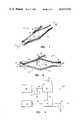
FIG. 1 is a perspective view of a velocity sensor probe;
FIG. 2 is a cross-section of the probe taken along the line 2--2 of FIG. 1;
FIG. 3 is a block diagram of a control circuit;
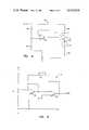
FIG. 4 is a schematic diagram of a compensation sensor constant current generator;
FIG. 5 is a schematic diagram of a compensation signal amplifier;
FIG. 6 is a schematic diagram of a heated sensor controllable constant current generator;
FIG. 7 is a schematic diagram of an automatic start-up current supply;
FIG. 8 is a perspective view of a velocity sensor probe; and,
FIG. 9 is a cross-section of the probe taken along thelines 9--9 of FIG. 8.
The present invention is especially adapted for measuring the flow of slowly moving air in an air conditioning system. The relatively low air flow levels found in such systems require that the velocity sensor accurately detect changes in these flows. The sensor and control circuit used in the preferred embodiment ensure accuracy in the measured air velocity.
Referring to FIG. 1, a detection probe, suitable for insertion into a moving air stream and designated generally by thereference numeral 8, has ahousing 10. Acalibrating thermistor 12 is mounted on the outside of thehousing 10, and is spaced a short distance from the outer surface thereof. A detectingthermistor 14 is suspended in the hollow interior of thecasing 10 by support leads 16. The support leads 16 are electrically conductive and mechanically couple the detectingthermistor 14 to the exterior of thecasing 10.Electrical leads 18 are coupled to theinterior thermistor 14 andleads 20 are coupled to theexterior thermistor 12 to connect bothsensors
Referring to FIG. 2, a cross-section of thesensor casing 10 is shown. Air flows through thecasing 10 from right to left as indicated byair flow arrows 22. Anintake end 24 of thecasing 10 is cylindrical. Downstream of theintake end 24 is a divergingcone section 26. Thecasing 10 increases in cross-section in the divergingcone section 26, then decreases in cross-section in a convergingcone section 28. The converging cone section is followed by anarrow channel 30, and adischarge end 32 of thecasing 10 expands to the same cross-section as theintake end 24.
The detectingthermistor 14 is suspended along the central axis of thehousing 10 near the junction of the divergingcone 26 and the convergingcone 28. Thecompensation thermistor 12 is supported on the outside of thecasing 10 at a point near to the detectingthermistor 14. In an alternate embodiment (FIG. 8 and FIG. 9), thecompensation thermistor 12 is supported inside of thecasing 10 along the central axis at a point upstream of the detectingthermistor 14. In this arrangement, the thermistors are separated by a distance great enough so that the radiation heating effect is insignificant.
Air entering theintake end 24 gradually expands, followed by a gradual compression as thechannel 30 is approached. Thenarrow channel 30 provides back pressure in thecasing 10, which decreases turbulence. Experience has shown that this shape for theprobe 8 provides a relatively smooth output from theheated sensor 14, as opposed to an erratic output due to turbulence.
Thedetection thermistor 14 is heated to an operating temperature substantially above the ambient temperature of the air. This is accomplished by the circuitry discussed below in FIGS. 3 through 7. The non-turbulent constant flow of air moving by thethermistor 14 carries away heat and cools thedetection thermistor 14. Thedetection thermistor 14 is preferably a negative temperature coefficient (NTC) thermistor so that its resistance rises as its temperature decreases.
An operating temperature for thethermistor 14 is chosen so that the change in power dissipated by theheated thermistor 14 will vary linearly with duct temperature changes at a constant air flow velocity. The preferred embodiment operates with thehot sensor 14 heated to approximately 300 degrees centigrade.
A block diagram of acontrol circuit 36 for use with theflow probe 8 is shown in FIG. 3. Acurrent generator 38 conducts a constant current through thecompensation thermistor 12. This current is low enough so that the temperature of thecompensation sensor 12 is not raised substantially due to resistance heating. Avoltage 40, developed across thecold sensor 12 by the constantcurrent source 38, varies in response to changes in the resistance of thecold sensor 12 induced by changes in the temperature of the ambient air. Thecold sensor voltage 40 is detected by acompensation sensor amplifier 42. Thesignal 44 generated by thecompensation amplifier 42 controls the current generated by a constantcurrent generator 46. The gain of thecompensation amplifier 42 is adjustable through a variable resistor R1 to compensate for variations in operating conditions.
Thecurrent supply 46 conducts an energizing current through the detectingthermistor 14. The precise level of current through theheated thermistor 14 is controlled by thecompensation signal 44, which makes its operation independent of air stream temperature changes. Thus, thevoltage 47 developed across theheated sensor 14 is proportional only to the velocity of the air flow.
To assist in start-up from a cold start situation, anautomatic starting circuit 48 is coupled to thehot detector 14 through the constantcurrent generator 46. Theauto start circuit 48 generates a highcurrent surge signal 49 to initially heat the detectingsensor 14 to its operating temperature.
In operation, a constant current is conducted through thecompensation sensor 12. Thesensor 12 operates in a relatively cool state so that fluid flow has very little effect on its temperature. Therefore, the temperature of thecompensation sensor 12 varies with the temperature of the ambient air, and is substantially independent of the velocity of the ambient air. Thecompensation sensor 12 is preferably a positive temperature coefficient thermistor, so that the resistance decreases with decreasing temperature. Therefore, thevoltage 40 across thecompensation sensor 12 rises and falls in direct relation to the temperature of the air flowing past of theprobe 8.
Thecompensation sensor voltage 40 is amplified in thecompensation amplifier 42 and is coupled to the controlledcurrent generator 46. The purpose of correcting the detection sensor current is to compensate for the increased heat exchange capacity of colder air passing across thehot thermistor 14, thereby preventing a false indication of increased air velocity. The level of current supplied to the detectingthermistor 14 changes in proportion to the compensatingsensor voltage 40. Assuming constant velocity of the air flow, if the air temperature decreases, the resistance of thehot thermistor 14 will increase due to the increased rate of heat exchange. Therefore, the controlled current through thehot thermistor 14 is decreased so that thesensor voltage 47 is not influenced by changes in air stream temperature.
The preferred operating temperature for the detectingsensor 14 of the present embodiment is approximately 300 degrees centigrade. The controlledcurrent supply 46 of the preferred embodiment, as discussed in connection with FIG. 6, drives thehot sensor 14 in this temperature region. The preferred detectorcurrent generator 46 may not bring the detectingsensor 14 up to operating temperature as quickly as desired. Therefore, anautomatic start circuit 48 applies a highcurrent surge 49 to theheated thermistor 14, and interrupts auto start current to thethermistor 14 once it has substantially reached the operating temperature.
Thevoltage 47 across the detectingthermistor sensor 14 varies directly with the velocity of air moving past the detector. High velocity air flow causes thehot sensor 14 to cool faster due to increased heat exchange, which increases its resistance. The controlled current supplied through an increasing resistance generates ahigher voltage 47. Likewise, a decrease in air velocity causes a decrease in thevoltage 47 across the detectingsensor 14.
A preferred embodiment of a compensating constantcurrent supply 38 is shown in FIG. 4. Supply voltage Vo is connected to a twelve volt regulated voltage supply (not shown). Operation in response to fluctuations in temperature of the ambient air near theprobe 8 will be discussed, assuming equilibrium conditions.
The current through a transistor Q1 is controlled by an operational amplifier (OP AMP) OA1. Q1 is biased by collector resistor R2 and fixed emitter resistor R3. The current level is controlled by a voltage divider comprised of resistors R5 and R6, coupled to the negative input of OA1. Collector voltage V1 is connected to the positive input of OA1. Any tendency for the transistor current to increase increases the voltage drop across R2, thereby decreasing V1. This tends to lower the output of OA1, tending to decrease the transistor Q1 current. The circuit operates to keep V1, and therefore the transistor Q1 current, constant.
This constant current passes through the compensatingthermistor 12. If thethermistor 12 cools, due to a drop in ambient air temperature, the resistance also drops because thethermistor 12 is a positive temperature coefficient thermistor. This drop in resistance also causes a drop in thecold thermistor voltage 40. An increase in temperature causes a corresponding increase in thethermistor voltage 40. Therefore, a positive correlation is produced between the ambient air temperature, an the compensatingthermistor voltage 40.
Referring to FIG. 5, a preferred embodiment for thecompensation amplifier 42 is shown. Thecompensation sensor voltage 40 is coupled to the positive input of a first scaling OP AMP OA2, which is operated as a differential amplifier. A second scaling OP AMP OA3 is used to provide a fixed voltage into the OP AMP OA2. The calibration adjusting resistor R1 is coupled to the negative input of OA3. A second variable resistor R7 is coupled in a feed back loop between the negative input of OA2 and the negative input of OA3 and provides for setting theminimum output voltage 44. Theoutput voltage 44 is used to control the constantcurrent source 46.
A preferred embodiment of a hot sensorcurrent source 46 is shown in FIG. 6. The current through thehot thermistor 14 is substantially equal to that through an output transistor Q2.
The present circuit operates in a similar manner to the compensation sensorcurrent source 38 discussed in FIG. 4. The collector voltage V2 of transistor Q2 is connected to the positive input of an OP AMP OA4. The negative input is connected to the compensatingamplifier output 44. The OP AMP OA4 operates to keep voltage V2, and thus, the current through Q2 and thethermistor 14, constant.
The negative input to the operational amplifier OA4 is coupled to the compensatingamplifier output 44. A decrease in ambient air temperature causes a decrease in thecompensation amplifier 44 output. When that happens, thevoltage 44 to the negative input of the operational amplifier OA4 of FIG. 6 decreases, tending to cause the OP AMP OA4 output voltage to increase. An increase in the output from OA4 tends to cause increase in the current through the output transistor Q2 by increasing the current through transistor Q3. Voltage V2 drops with increasing current, causing the output of OA4 to drop. The net result of a decrease in thecompensation amplifier output 44 is a increase in the current through output transistor Q2. The lower temperature of thehot sensor 14 due to a decrease in the ambient air temperature would normally tend to increase thedetector voltage 47. However, the increase indetector sensor 14 current caused by thelower voltage 44 to the negative input of OA4 causes thesensor voltage 47 to remain constant. Similarly thevoltage 47 across the self-heated thermistor 14 remains constant when the ambient temperature increases.
Theautomatic start circuit 48 is connected to the detectingthermistor 14. Thecircuit 48 provides increased current during a cold start-up of thethermistor 14, and automatically cuts off when the operating temperature is reached. Referring to FIG. 7, a preferred embodiment for anautomatic start circuit 48 is shown. Theautomatic starter output 49 is equal in magnitude to theheated thermistor voltage 47.
When the detectingthermistor 14 is operating in the high temperature region, its resistance is relatively low. This causes the autostarter output voltage 49 to also be low. Thisvoltage 49 is too low to cause avalanche breakdown of a zener diode D1, so that no current is supplied to the base of an NPN starter transistor Q4. Therefore, transistor Q4 is off. Since no current is flowing through a first collector resistor R9, the voltage at the base of the NPN transistor Q5 is substantially equal to a supply voltage V3. Since the base voltage of the second transistor Q5 is not lower than that at the emitter, transistor Q5 is also in the off state. Thestarter circuit 48 uses an 18 volt supply V3. This higher voltage allows more power to be delivered to theheated thermistor 14 for faster start-up.
When thehot sensor 14 is cool, its resistance is relatively high. This causes thestarter output voltage 49 to be high. Thisvoltage 49 is high enough to cause breakdown of the zener diode D1, which allows enough current to reach the base of the first starting transistor Q4 to begin conduction. As current flows into the collector of the first starting transistor Q4, the voltage at the base of the second starting transistor Q5 drops, causing transistor Q5 to begin conduction.
Part of the current conducted through the transistor Q5 goes into the base of the first transistor Q4 to turn it completely to the on state, while the remainder goes through thethermistor 14 and causes it to heat up at an increased rate. Increased conduction of the first starting transistor Q4 causes the second starting transistor Q5 to also conduct at an increased rate. A second collector resistor R10 is chosen to have a low resistance relative to that of the detectingthermistor 14 in the cold state, but higher than thethermistor 14 in the operating region. This allows most of the voltage created by current passing through the second starting transistor Q5 to be dropped across the detectingthermistor 14 instead of resistor R10.
The increased current flowing through the second starting transistor Q5 causes the detectingthermistor 14 to heat up at a greatly increased rate. As thethermistor 14 heats up, its resistance decreases. Once the resistance of thethermistor 14 decreases far enough, theoutput voltage 49 drops below the breakdown voltage of zener diode D1, and both starting transistors Q4 and Q5 go into the off state. This will occur when thevoltage 47 across the detectingthermistor 14 is slightly less than the breakdown voltage of the zener diode D1.
Although a preferred embodiment has been described in detail, it should be understood that various substitutions, alterations, and modifications may become apparent to those skilled in the art. These changes may be made without departing from the spirit and scope of the invention as defined by the appended claims.
Claims (8)
1. Apparatus for positioning within a slowly moving fluid medium for sensing fluid flow velocity therethrough, comprising:
(a) a tubular housing having intake and outlet ends;
(b) turbulence reducing means within said housing for reducing fluid flow turbulence to an acceptable level;
(c) a first thermistor disposed outside of said tubular housing;
(d) a first current supply for supplying constant current to said first thermistor to develop a voltage across said first thermistor which is proportional to the ambient temperature of the fluid medium outside said housing;
(e) a second thermistor disposed within said tubular housing;
(f) a second current supply responsive to the voltage across said first thermistor for supplying current to said second thermistor, which current is proportional to the ambient temperature of the fluid medium outside said housing,
whereby the voltage across said second thermistor is a function only of the temperature change of said second thermistor, independent of changes in the ambient temperature of the fluid outside said housing.
2. The apparatus as set forth in claim 1, wherein said first thermistor operates at substantially the same temperature as the ambient temperature of the fluid medium outside said housing, and said second thermistor operates at a temperature substantially greater than the temperature of the fluid flowing within said housing.
3. The apparatus as set forth in claim 2, further comprising heating means for applying a high current surge to said second thermistor to bring said second thermistor up to said operating temperature.
4. The apparatus as set forth in claim 3, said first thermistor is a positive temperature coefficient thermistor, and wherein said second thermistor is a negative temperature coefficient thermistor.
5. The apparatus as set forth in claim 1, wherein said turbulence reducing means within said housing comprises, in the direction of fluid flow: (1) a first stage of gradually increasing cross section; (2) a second stage of gradually decreasing cross section; and (3) a third stage comprising a flow restricting channel considerably smaller than said intake end.
6. A method for sensing fluid flow velocity within a slowly moving fluid medium, comprising the steps of:
(a) positioning a flow-through housing within said flowing fluid medium;
(b) positioning a first thermistor within said flowing fluid medium outside said housing;
(c) positioning a second thermistor within said housing;
(d) applying a constant current to said first thermistor to develop a voltage across said first thermistor which is proportional to the ambient temperature of fluid medium outside said housing;
(e) applying a second current to said second thermistor, said second current being a function of the voltage across said first thermistor;
(f) detecting the voltage across said second thermistor, which voltage is proportional to the fluid flow velocity within said fluid medium.
7. The method as set forth in claim 6, wherein said second current is proportional to the voltage across said first thermistor.
8. The method as set forth in claim 7, further comprising the step of applying an initial high current surge to said second thermistor to initially heat said second thermistor to a temperature substantially above the ambient temperature of the fluid medium.
Priority Applications (1)
| Application Number | Priority Date | Filing Date | Title |
|---|---|---|---|
| US06/266,487US4413514A (en) | 1981-05-22 | 1981-05-22 | Air flow sensor |
Applications Claiming Priority (1)
| Application Number | Priority Date | Filing Date | Title |
|---|---|---|---|
| US06/266,487US4413514A (en) | 1981-05-22 | 1981-05-22 | Air flow sensor |
Publications (1)
| Publication Number | Publication Date |
|---|---|
| US4413514Atrue US4413514A (en) | 1983-11-08 |
Family
ID=23014777
Family Applications (1)
| Application Number | Title | Priority Date | Filing Date |
|---|---|---|---|
| US06/266,487Expired - Fee RelatedUS4413514A (en) | 1981-05-22 | 1981-05-22 | Air flow sensor |
Country Status (1)
| Country | Link |
|---|---|
| US (1) | US4413514A (en) |
Cited By (36)
| Publication number | Priority date | Publication date | Assignee | Title |
|---|---|---|---|---|
| US4537068A (en)* | 1983-03-10 | 1985-08-27 | Dwyer Instruments, Inc. | Thermal anemometer |
| DE3417305A1 (en)* | 1984-05-10 | 1985-11-14 | Robert Bosch Gmbh, 7000 Stuttgart | DEVICE FOR MEASURING THE MASS OF A FLOWING MEDIUM |
| US4578996A (en)* | 1983-09-02 | 1986-04-01 | Nippondenso Co., Ltd. | Gas-flow measuring apparatus and method |
| US4581929A (en)* | 1983-11-04 | 1986-04-15 | Hitachi, Ltd. | Air flow meter circuit with temperature compensation circuit |
| US4581930A (en)* | 1984-08-30 | 1986-04-15 | Ebtron, Inc. | Average mass flow rate meter using self-heated thermistors |
| US4599895A (en)* | 1984-07-12 | 1986-07-15 | Wiseman Donald F | Method and apparatus for measuring fluid flow |
| US4686450A (en)* | 1986-04-04 | 1987-08-11 | General Signal Corporation | Fluid flow sensor |
| US4838484A (en)* | 1987-07-31 | 1989-06-13 | Kreuter Manufacturing Co., Inc. | Variable volume air conditioning system with velocity readout at the thermostat |
| GB2217018A (en)* | 1988-03-18 | 1989-10-18 | Pierburg Gmbh | Device for gas flow measurement |
| US20050223515A1 (en)* | 2004-04-13 | 2005-10-13 | Oreck Holdings, Llc | Airflow sensor system for monitoring air inlet airflow and air outlet airflow of a vacuum cleaner |
| WO2008019102A3 (en)* | 2006-08-03 | 2008-07-03 | Breathe Technologies Inc | Methods and devices for minimally invasive respiratory support |
| US20080186621A1 (en)* | 2007-02-05 | 2008-08-07 | Charles Partee | Disk Drive Fly Height Monitoring Arrangement and Method |
| US7487778B2 (en) | 2003-08-11 | 2009-02-10 | Breathe Technologies, Inc. | Tracheal catheter and prosthesis and method of respiratory support of a patient |
| US7533670B1 (en) | 2005-09-20 | 2009-05-19 | Breathe Technologies, Inc. | Systems, methods and apparatus for respiratory support of a patient |
| US7588033B2 (en) | 2003-06-18 | 2009-09-15 | Breathe Technologies, Inc. | Methods, systems and devices for improving ventilation in a lung area |
| US7631642B2 (en) | 2006-05-18 | 2009-12-15 | Breathe Technologies, Inc. | Tracheostoma spacer, tracheotomy method, and device for inserting a tracheostoma spacer |
| US8136527B2 (en) | 2003-08-18 | 2012-03-20 | Breathe Technologies, Inc. | Method and device for non-invasive ventilation with nasal interface |
| DE102011103175A1 (en)* | 2011-06-01 | 2012-12-06 | Sensus Spectrum Llc | Measuring device for measuring the flow of a fluid |
| US8567399B2 (en) | 2007-09-26 | 2013-10-29 | Breathe Technologies, Inc. | Methods and devices for providing inspiratory and expiratory flow relief during ventilation therapy |
| US8594953B2 (en) | 2011-03-09 | 2013-11-26 | ClearWater Tech, LLC | Intelligent gas flow sensor probe |
| US8677999B2 (en) | 2008-08-22 | 2014-03-25 | Breathe Technologies, Inc. | Methods and devices for providing mechanical ventilation with an open airway interface |
| US8770193B2 (en) | 2008-04-18 | 2014-07-08 | Breathe Technologies, Inc. | Methods and devices for sensing respiration and controlling ventilator functions |
| US8776793B2 (en) | 2008-04-18 | 2014-07-15 | Breathe Technologies, Inc. | Methods and devices for sensing respiration and controlling ventilator functions |
| US8925545B2 (en) | 2004-02-04 | 2015-01-06 | Breathe Technologies, Inc. | Methods and devices for treating sleep apnea |
| US8939152B2 (en) | 2010-09-30 | 2015-01-27 | Breathe Technologies, Inc. | Methods, systems and devices for humidifying a respiratory tract |
| US9132250B2 (en) | 2009-09-03 | 2015-09-15 | Breathe Technologies, Inc. | Methods, systems and devices for non-invasive ventilation including a non-sealing ventilation interface with an entrainment port and/or pressure feature |
| WO2015142552A1 (en)* | 2014-03-20 | 2015-09-24 | Varian Semiconductor Equipment Associates, Inc. | Thermistor based measurement system |
| US9180270B2 (en) | 2009-04-02 | 2015-11-10 | Breathe Technologies, Inc. | Methods, systems and devices for non-invasive open ventilation with gas delivery nozzles within an outer tube |
| US9962512B2 (en) | 2009-04-02 | 2018-05-08 | Breathe Technologies, Inc. | Methods, systems and devices for non-invasive ventilation including a non-sealing ventilation interface with a free space nozzle feature |
| US10058668B2 (en) | 2007-05-18 | 2018-08-28 | Breathe Technologies, Inc. | Methods and devices for sensing respiration and providing ventilation therapy |
| US10099028B2 (en) | 2010-08-16 | 2018-10-16 | Breathe Technologies, Inc. | Methods, systems and devices using LOX to provide ventilatory support |
| WO2018222643A1 (en)* | 2017-05-30 | 2018-12-06 | Verily Life Sciences Llc | Inhaler devices for monitoring airflow |
| US10252020B2 (en) | 2008-10-01 | 2019-04-09 | Breathe Technologies, Inc. | Ventilator with biofeedback monitoring and control for improving patient activity and health |
| WO2020178403A1 (en)* | 2019-03-05 | 2020-09-10 | Ntn-Snr Roulements | System and method for detecting a flow of a fluid or pasty product using a thermistor and associated grease lubrication circuit |
| US10792449B2 (en) | 2017-10-03 | 2020-10-06 | Breathe Technologies, Inc. | Patient interface with integrated jet pump |
| US11154672B2 (en) | 2009-09-03 | 2021-10-26 | Breathe Technologies, Inc. | Methods, systems and devices for non-invasive ventilation including a non-sealing ventilation interface with an entrainment port and/or pressure feature |
Citations (8)
| Publication number | Priority date | Publication date | Assignee | Title |
|---|---|---|---|---|
| US3068693A (en)* | 1958-09-22 | 1962-12-18 | Trans Sonics Inc | Mass flow meter |
| US3123900A (en)* | 1964-03-10 | Method of manufacture of a flow element or pulsation dampener | ||
| US3220255A (en)* | 1962-12-03 | 1965-11-30 | Technology Inc | Thermal mass flowmeter |
| US3363462A (en)* | 1964-09-30 | 1968-01-16 | Cullen M. Sabin | Fluid anemometer system |
| US3372590A (en)* | 1965-10-01 | 1968-03-12 | Technology Inc | Thermal flowmeter |
| US3735752A (en)* | 1971-04-07 | 1973-05-29 | J Rodder | Spirometer |
| US3891391A (en)* | 1973-05-14 | 1975-06-24 | George R Boone | Fluid flow measuring system using improved temperature compensation apparatus and method |
| US4343183A (en)* | 1979-02-22 | 1982-08-10 | Robert Bosch Gmbh | Apparatus for measuring air flow in the air intake manifold of an internal combustion engine |
- 1981
- 1981-05-22USUS06/266,487patent/US4413514A/ennot_activeExpired - Fee Related
Patent Citations (8)
| Publication number | Priority date | Publication date | Assignee | Title |
|---|---|---|---|---|
| US3123900A (en)* | 1964-03-10 | Method of manufacture of a flow element or pulsation dampener | ||
| US3068693A (en)* | 1958-09-22 | 1962-12-18 | Trans Sonics Inc | Mass flow meter |
| US3220255A (en)* | 1962-12-03 | 1965-11-30 | Technology Inc | Thermal mass flowmeter |
| US3363462A (en)* | 1964-09-30 | 1968-01-16 | Cullen M. Sabin | Fluid anemometer system |
| US3372590A (en)* | 1965-10-01 | 1968-03-12 | Technology Inc | Thermal flowmeter |
| US3735752A (en)* | 1971-04-07 | 1973-05-29 | J Rodder | Spirometer |
| US3891391A (en)* | 1973-05-14 | 1975-06-24 | George R Boone | Fluid flow measuring system using improved temperature compensation apparatus and method |
| US4343183A (en)* | 1979-02-22 | 1982-08-10 | Robert Bosch Gmbh | Apparatus for measuring air flow in the air intake manifold of an internal combustion engine |
Cited By (63)
| Publication number | Priority date | Publication date | Assignee | Title |
|---|---|---|---|---|
| US4537068A (en)* | 1983-03-10 | 1985-08-27 | Dwyer Instruments, Inc. | Thermal anemometer |
| US4578996A (en)* | 1983-09-02 | 1986-04-01 | Nippondenso Co., Ltd. | Gas-flow measuring apparatus and method |
| USRE33076E (en)* | 1983-11-04 | 1989-10-03 | Hitachi, Ltd. | Air flow meter circuit with temperature compensation circuit |
| US4581929A (en)* | 1983-11-04 | 1986-04-15 | Hitachi, Ltd. | Air flow meter circuit with temperature compensation circuit |
| DE3417305A1 (en)* | 1984-05-10 | 1985-11-14 | Robert Bosch Gmbh, 7000 Stuttgart | DEVICE FOR MEASURING THE MASS OF A FLOWING MEDIUM |
| US4599895A (en)* | 1984-07-12 | 1986-07-15 | Wiseman Donald F | Method and apparatus for measuring fluid flow |
| US4581930A (en)* | 1984-08-30 | 1986-04-15 | Ebtron, Inc. | Average mass flow rate meter using self-heated thermistors |
| US4686450A (en)* | 1986-04-04 | 1987-08-11 | General Signal Corporation | Fluid flow sensor |
| US4838484A (en)* | 1987-07-31 | 1989-06-13 | Kreuter Manufacturing Co., Inc. | Variable volume air conditioning system with velocity readout at the thermostat |
| GB2217018A (en)* | 1988-03-18 | 1989-10-18 | Pierburg Gmbh | Device for gas flow measurement |
| US8955518B2 (en) | 2003-06-18 | 2015-02-17 | Breathe Technologies, Inc. | Methods, systems and devices for improving ventilation in a lung area |
| US8381729B2 (en) | 2003-06-18 | 2013-02-26 | Breathe Technologies, Inc. | Methods and devices for minimally invasive respiratory support |
| US7588033B2 (en) | 2003-06-18 | 2009-09-15 | Breathe Technologies, Inc. | Methods, systems and devices for improving ventilation in a lung area |
| US8418694B2 (en) | 2003-08-11 | 2013-04-16 | Breathe Technologies, Inc. | Systems, methods and apparatus for respiratory support of a patient |
| US7487778B2 (en) | 2003-08-11 | 2009-02-10 | Breathe Technologies, Inc. | Tracheal catheter and prosthesis and method of respiratory support of a patient |
| US8136527B2 (en) | 2003-08-18 | 2012-03-20 | Breathe Technologies, Inc. | Method and device for non-invasive ventilation with nasal interface |
| US8573219B2 (en) | 2003-08-18 | 2013-11-05 | Breathe Technologies, Inc. | Method and device for non-invasive ventilation with nasal interface |
| US8925545B2 (en) | 2004-02-04 | 2015-01-06 | Breathe Technologies, Inc. | Methods and devices for treating sleep apnea |
| US7210194B2 (en)* | 2004-04-13 | 2007-05-01 | Oreck Holdings, Llc | Airflow sensor system for monitoring air inlet airflow and air outlet airflow of a vacuum cleaner |
| US20050223515A1 (en)* | 2004-04-13 | 2005-10-13 | Oreck Holdings, Llc | Airflow sensor system for monitoring air inlet airflow and air outlet airflow of a vacuum cleaner |
| US7533670B1 (en) | 2005-09-20 | 2009-05-19 | Breathe Technologies, Inc. | Systems, methods and apparatus for respiratory support of a patient |
| US7631642B2 (en) | 2006-05-18 | 2009-12-15 | Breathe Technologies, Inc. | Tracheostoma spacer, tracheotomy method, and device for inserting a tracheostoma spacer |
| US8985099B2 (en) | 2006-05-18 | 2015-03-24 | Breathe Technologies, Inc. | Tracheostoma spacer, tracheotomy method, and device for inserting a tracheostoma spacer |
| WO2008019102A3 (en)* | 2006-08-03 | 2008-07-03 | Breathe Technologies Inc | Methods and devices for minimally invasive respiratory support |
| US20080186621A1 (en)* | 2007-02-05 | 2008-08-07 | Charles Partee | Disk Drive Fly Height Monitoring Arrangement and Method |
| US10058668B2 (en) | 2007-05-18 | 2018-08-28 | Breathe Technologies, Inc. | Methods and devices for sensing respiration and providing ventilation therapy |
| US8567399B2 (en) | 2007-09-26 | 2013-10-29 | Breathe Technologies, Inc. | Methods and devices for providing inspiratory and expiratory flow relief during ventilation therapy |
| EP2274036A4 (en)* | 2008-04-18 | 2014-08-13 | Breathe Technologies Inc | Methods and devices for sensing respiration and controlling ventilator functions |
| US8770193B2 (en) | 2008-04-18 | 2014-07-08 | Breathe Technologies, Inc. | Methods and devices for sensing respiration and controlling ventilator functions |
| US8776793B2 (en) | 2008-04-18 | 2014-07-15 | Breathe Technologies, Inc. | Methods and devices for sensing respiration and controlling ventilator functions |
| US8677999B2 (en) | 2008-08-22 | 2014-03-25 | Breathe Technologies, Inc. | Methods and devices for providing mechanical ventilation with an open airway interface |
| US10252020B2 (en) | 2008-10-01 | 2019-04-09 | Breathe Technologies, Inc. | Ventilator with biofeedback monitoring and control for improving patient activity and health |
| US9180270B2 (en) | 2009-04-02 | 2015-11-10 | Breathe Technologies, Inc. | Methods, systems and devices for non-invasive open ventilation with gas delivery nozzles within an outer tube |
| US12161807B2 (en) | 2009-04-02 | 2024-12-10 | Breathe Technologies, Inc. | Methods, systems and devices for non-invasive open ventilation with gas delivery nozzles within nasal pillows |
| US10232136B2 (en) | 2009-04-02 | 2019-03-19 | Breathe Technologies, Inc. | Methods, systems and devices for non-invasive open ventilation for treating airway obstructions |
| US11896766B2 (en) | 2009-04-02 | 2024-02-13 | Breathe Technologies, Inc. | Methods, systems and devices for non-invasive ventilation with gas delivery nozzles in free space |
| US12364835B2 (en) | 2009-04-02 | 2025-07-22 | Breathe Technologies, Inc. | Methods, systems and devices for non-invasive ventilation with gas delivery nozzles in free space |
| US9227034B2 (en) | 2009-04-02 | 2016-01-05 | Beathe Technologies, Inc. | Methods, systems and devices for non-invasive open ventilation for treating airway obstructions |
| US10695519B2 (en) | 2009-04-02 | 2020-06-30 | Breathe Technologies, Inc. | Methods, systems and devices for non-invasive open ventilation with gas delivery nozzles within nasal pillows |
| US11103667B2 (en) | 2009-04-02 | 2021-08-31 | Breathe Technologies, Inc. | Methods, systems and devices for non-invasive ventilation with gas delivery nozzles in free space |
| US9675774B2 (en) | 2009-04-02 | 2017-06-13 | Breathe Technologies, Inc. | Methods, systems and devices for non-invasive open ventilation with gas delivery nozzles in free space |
| US9962512B2 (en) | 2009-04-02 | 2018-05-08 | Breathe Technologies, Inc. | Methods, systems and devices for non-invasive ventilation including a non-sealing ventilation interface with a free space nozzle feature |
| US10046133B2 (en) | 2009-04-02 | 2018-08-14 | Breathe Technologies, Inc. | Methods, systems and devices for non-invasive open ventilation for providing ventilation support |
| US10709864B2 (en) | 2009-04-02 | 2020-07-14 | Breathe Technologies, Inc. | Methods, systems and devices for non-invasive open ventilation with gas delivery nozzles with an outer tube |
| US12048813B2 (en) | 2009-09-03 | 2024-07-30 | Breathe Technologies, Inc. | Methods, systems and devices for non-invasive ventilation including a non-sealing ventilation interface with an entrainment port and/or pressure feature |
| US11154672B2 (en) | 2009-09-03 | 2021-10-26 | Breathe Technologies, Inc. | Methods, systems and devices for non-invasive ventilation including a non-sealing ventilation interface with an entrainment port and/or pressure feature |
| US9132250B2 (en) | 2009-09-03 | 2015-09-15 | Breathe Technologies, Inc. | Methods, systems and devices for non-invasive ventilation including a non-sealing ventilation interface with an entrainment port and/or pressure feature |
| US10265486B2 (en) | 2009-09-03 | 2019-04-23 | Breathe Technologies, Inc. | Methods, systems and devices for non-invasive ventilation including a non-sealing ventilation interface with an entrainment port and/or pressure feature |
| US10099028B2 (en) | 2010-08-16 | 2018-10-16 | Breathe Technologies, Inc. | Methods, systems and devices using LOX to provide ventilatory support |
| US9358358B2 (en) | 2010-09-30 | 2016-06-07 | Breathe Technologies, Inc. | Methods, systems and devices for humidifying a respiratory tract |
| US8939152B2 (en) | 2010-09-30 | 2015-01-27 | Breathe Technologies, Inc. | Methods, systems and devices for humidifying a respiratory tract |
| US8594953B2 (en) | 2011-03-09 | 2013-11-26 | ClearWater Tech, LLC | Intelligent gas flow sensor probe |
| JP2014515491A (en)* | 2011-06-01 | 2014-06-30 | センサス スペクトラム エルエルシー | Measuring device for measuring fluid flow rate |
| DE102011103175A1 (en)* | 2011-06-01 | 2012-12-06 | Sensus Spectrum Llc | Measuring device for measuring the flow of a fluid |
| EP2715293B1 (en)* | 2011-06-01 | 2020-02-26 | Sensus Spectrum LLC | Measuring device with thermal sensor for measuring a fluid flow rate |
| WO2015142552A1 (en)* | 2014-03-20 | 2015-09-24 | Varian Semiconductor Equipment Associates, Inc. | Thermistor based measurement system |
| US9494470B2 (en) | 2014-03-20 | 2016-11-15 | Varian Semiconductor Equipment Associates, Inc. | Thermistor based measurement system |
| EP3868431A1 (en)* | 2017-05-30 | 2021-08-25 | Verily Life Sciences LLC | Inhaler devices for monitoring airflow |
| WO2018222643A1 (en)* | 2017-05-30 | 2018-12-06 | Verily Life Sciences Llc | Inhaler devices for monitoring airflow |
| US10792449B2 (en) | 2017-10-03 | 2020-10-06 | Breathe Technologies, Inc. | Patient interface with integrated jet pump |
| US12017002B2 (en) | 2017-10-03 | 2024-06-25 | Breathe Technologies, Inc. | Patient interface with integrated jet pump |
| FR3093562A1 (en)* | 2019-03-05 | 2020-09-11 | Ntn-Snr Roulements | system and method for detecting a flow of fluid or pasty product by thermistor and associated grease lubrication circuit |
| WO2020178403A1 (en)* | 2019-03-05 | 2020-09-10 | Ntn-Snr Roulements | System and method for detecting a flow of a fluid or pasty product using a thermistor and associated grease lubrication circuit |
Similar Documents
| Publication | Publication Date | Title |
|---|---|---|
| US4413514A (en) | Air flow sensor | |
| US4487213A (en) | Mass flow controller apparatus | |
| US3992940A (en) | Solid state fluid flow sensor | |
| JP2704048B2 (en) | Current difference type thermal mass flow transducer | |
| US4041757A (en) | Fluid flowmeter | |
| US4653321A (en) | Method of automatically measuring fluid flow rates | |
| KR0184673B1 (en) | Thermal type flowmeter | |
| US4125093A (en) | Solid state fluid flow sensor | |
| US4564748A (en) | Variable temperature heating control system for inhalation therapy apparatus | |
| US4464932A (en) | Thermal mass flowmetering | |
| US4135396A (en) | Temperature compensating fluid velocity sensing apparatus | |
| US4217761A (en) | Heat pump output indicator | |
| US3757808A (en) | Electronic mass airflow sensing and control system | |
| US3372590A (en) | Thermal flowmeter | |
| JPH0349374B2 (en) | ||
| US4982605A (en) | Air flow monitor and temperature compensating circuit therefor | |
| US3597676A (en) | Thermistor circuit for use in an angular movement sensing device | |
| JP2952438B2 (en) | Thermal flow meter | |
| JP2962695B2 (en) | Fluid detector | |
| JP3637278B2 (en) | 2-sensor flow meter | |
| JP2599854B2 (en) | How to set the thermal flow sensor | |
| US6539791B1 (en) | Method and apparatus for measuring flow based on heat transfer from a flowing medium | |
| US4400975A (en) | Apparatus for monitoring liquid flow rates | |
| GB2173905A (en) | Fluid-flow monitoring apparatus | |
| JP3706283B2 (en) | Flow sensor circuit |
Legal Events
| Date | Code | Title | Description |
|---|---|---|---|
| AS | Assignment | Owner name:HOFFMAN CONTROLS CORPORATION, 2463 MERRELL RD., DA Free format text:ASSIGNMENT OF ASSIGNORS INTEREST.;ASSIGNOR:BOWMAN WILLIAM W.;REEL/FRAME:003889/0558 Effective date:19810430 Owner name:HOFFMAN CONTROLS CORPORATION, TEXAS Free format text:ASSIGNMENT OF ASSIGNORS INTEREST;ASSIGNOR:BOWMAN WILLIAM W.;REEL/FRAME:003889/0558 Effective date:19810430 | |
| MAFP | Maintenance fee payment | Free format text:PAYMENT OF MAINTENANCE FEE, 4TH YEAR, PL 96-517 (ORIGINAL EVENT CODE: M170); ENTITY STATUS OF PATENT OWNER: LARGE ENTITY Year of fee payment:4 | |
| FEPP | Fee payment procedure | Free format text:MAINTENANCE FEE REMINDER MAILED (ORIGINAL EVENT CODE: REM.); ENTITY STATUS OF PATENT OWNER: LARGE ENTITY | |
| LAPS | Lapse for failure to pay maintenance fees | ||
| FP | Lapsed due to failure to pay maintenance fee | Effective date:19911110 | |
| STCH | Information on status: patent discontinuation | Free format text:PATENT EXPIRED DUE TO NONPAYMENT OF MAINTENANCE FEES UNDER 37 CFR 1.362 |