US4413407A - Method for forming an electrode-containing device with capillary transport between electrodes - Google Patents
Method for forming an electrode-containing device with capillary transport between electrodesDownload PDFInfo
- Publication number
- US4413407A US4413407AUS06/319,568US31956881AUS4413407AUS 4413407 AUS4413407 AUS 4413407AUS 31956881 AUS31956881 AUS 31956881AUS 4413407 AUS4413407 AUS 4413407A
- Authority
- US
- United States
- Prior art keywords
- liquid
- sheet
- electrodes
- apertures
- zone
- Prior art date
- Legal status (The legal status is an assumption and is not a legal conclusion. Google has not performed a legal analysis and makes no representation as to the accuracy of the status listed.)
- Expired - Fee Related
Links
Images


Classifications
- G—PHYSICS
- G01—MEASURING; TESTING
- G01N—INVESTIGATING OR ANALYSING MATERIALS BY DETERMINING THEIR CHEMICAL OR PHYSICAL PROPERTIES
- G01N27/00—Investigating or analysing materials by the use of electric, electrochemical, or magnetic means
- G01N27/26—Investigating or analysing materials by the use of electric, electrochemical, or magnetic means by investigating electrochemical variables; by using electrolysis or electrophoresis
- G01N27/28—Electrolytic cell components
- G01N27/30—Electrodes, e.g. test electrodes; Half-cells
- G01N27/307—Disposable laminated or multilayered electrodes
- B—PERFORMING OPERATIONS; TRANSPORTING
- B01—PHYSICAL OR CHEMICAL PROCESSES OR APPARATUS IN GENERAL
- B01L—CHEMICAL OR PHYSICAL LABORATORY APPARATUS FOR GENERAL USE
- B01L3/00—Containers or dishes for laboratory use, e.g. laboratory glassware; Droppers
- B01L3/50—Containers for the purpose of retaining a material to be analysed, e.g. test tubes
- B01L3/502—Containers for the purpose of retaining a material to be analysed, e.g. test tubes with fluid transport, e.g. in multi-compartment structures
- B01L3/5027—Containers for the purpose of retaining a material to be analysed, e.g. test tubes with fluid transport, e.g. in multi-compartment structures by integrated microfluidic structures, i.e. dimensions of channels and chambers are such that surface tension forces are important, e.g. lab-on-a-chip
- B01L3/50273—Containers for the purpose of retaining a material to be analysed, e.g. test tubes with fluid transport, e.g. in multi-compartment structures by integrated microfluidic structures, i.e. dimensions of channels and chambers are such that surface tension forces are important, e.g. lab-on-a-chip characterised by the means or forces applied to move the fluids
- B—PERFORMING OPERATIONS; TRANSPORTING
- B01—PHYSICAL OR CHEMICAL PROCESSES OR APPARATUS IN GENERAL
- B01L—CHEMICAL OR PHYSICAL LABORATORY APPARATUS FOR GENERAL USE
- B01L2200/00—Solutions for specific problems relating to chemical or physical laboratory apparatus
- B01L2200/06—Fluid handling related problems
- B01L2200/0684—Venting, avoiding backpressure, avoid gas bubbles
- B—PERFORMING OPERATIONS; TRANSPORTING
- B01—PHYSICAL OR CHEMICAL PROCESSES OR APPARATUS IN GENERAL
- B01L—CHEMICAL OR PHYSICAL LABORATORY APPARATUS FOR GENERAL USE
- B01L2200/00—Solutions for specific problems relating to chemical or physical laboratory apparatus
- B01L2200/12—Specific details about manufacturing devices
- B—PERFORMING OPERATIONS; TRANSPORTING
- B01—PHYSICAL OR CHEMICAL PROCESSES OR APPARATUS IN GENERAL
- B01L—CHEMICAL OR PHYSICAL LABORATORY APPARATUS FOR GENERAL USE
- B01L2300/00—Additional constructional details
- B01L2300/06—Auxiliary integrated devices, integrated components
- B01L2300/0627—Sensor or part of a sensor is integrated
- B01L2300/0645—Electrodes
- B—PERFORMING OPERATIONS; TRANSPORTING
- B01—PHYSICAL OR CHEMICAL PROCESSES OR APPARATUS IN GENERAL
- B01L—CHEMICAL OR PHYSICAL LABORATORY APPARATUS FOR GENERAL USE
- B01L2300/00—Additional constructional details
- B01L2300/08—Geometry, shape and general structure
- B01L2300/0809—Geometry, shape and general structure rectangular shaped
- B01L2300/0816—Cards, e.g. flat sample carriers usually with flow in two horizontal directions
- B—PERFORMING OPERATIONS; TRANSPORTING
- B01—PHYSICAL OR CHEMICAL PROCESSES OR APPARATUS IN GENERAL
- B01L—CHEMICAL OR PHYSICAL LABORATORY APPARATUS FOR GENERAL USE
- B01L2300/00—Additional constructional details
- B01L2300/08—Geometry, shape and general structure
- B01L2300/0809—Geometry, shape and general structure rectangular shaped
- B01L2300/0825—Test strips
- B—PERFORMING OPERATIONS; TRANSPORTING
- B01—PHYSICAL OR CHEMICAL PROCESSES OR APPARATUS IN GENERAL
- B01L—CHEMICAL OR PHYSICAL LABORATORY APPARATUS FOR GENERAL USE
- B01L2300/00—Additional constructional details
- B01L2300/08—Geometry, shape and general structure
- B01L2300/0887—Laminated structure
- B—PERFORMING OPERATIONS; TRANSPORTING
- B01—PHYSICAL OR CHEMICAL PROCESSES OR APPARATUS IN GENERAL
- B01L—CHEMICAL OR PHYSICAL LABORATORY APPARATUS FOR GENERAL USE
- B01L2300/00—Additional constructional details
- B01L2300/08—Geometry, shape and general structure
- B01L2300/089—Virtual walls for guiding liquids
- B—PERFORMING OPERATIONS; TRANSPORTING
- B01—PHYSICAL OR CHEMICAL PROCESSES OR APPARATUS IN GENERAL
- B01L—CHEMICAL OR PHYSICAL LABORATORY APPARATUS FOR GENERAL USE
- B01L2400/00—Moving or stopping fluids
- B01L2400/04—Moving fluids with specific forces or mechanical means
- B01L2400/0403—Moving fluids with specific forces or mechanical means specific forces
- B01L2400/0406—Moving fluids with specific forces or mechanical means specific forces capillary forces
- B—PERFORMING OPERATIONS; TRANSPORTING
- B01—PHYSICAL OR CHEMICAL PROCESSES OR APPARATUS IN GENERAL
- B01L—CHEMICAL OR PHYSICAL LABORATORY APPARATUS FOR GENERAL USE
- B01L2400/00—Moving or stopping fluids
- B01L2400/06—Valves, specific forms thereof
- B01L2400/0688—Valves, specific forms thereof surface tension valves, capillary stop, capillary break
- Y—GENERAL TAGGING OF NEW TECHNOLOGICAL DEVELOPMENTS; GENERAL TAGGING OF CROSS-SECTIONAL TECHNOLOGIES SPANNING OVER SEVERAL SECTIONS OF THE IPC; TECHNICAL SUBJECTS COVERED BY FORMER USPC CROSS-REFERENCE ART COLLECTIONS [XRACs] AND DIGESTS
- Y10—TECHNICAL SUBJECTS COVERED BY FORMER USPC
- Y10T—TECHNICAL SUBJECTS COVERED BY FORMER US CLASSIFICATION
- Y10T29/00—Metal working
- Y10T29/49—Method of mechanical manufacture
- Y10T29/49002—Electrical device making
- Y10T29/49117—Conductor or circuit manufacturing
Definitions
- This inventionrelates to a device for determining the activity and therefore the concentration of electrolytes in a liquid.
- Such devicesare valuable quantitative tools in the field of clinical chemistry to determine the existence and cause of certain body illnesses and abnormalities.
- ISE'sion-selective electrodes
- U.S. Pat. No. 4,053,381issued Oct. 11, 1977.
- the ISE's of such a deviceare overlaid or otherwise contacted with an ion bridge that provides for ionic flow between a drop of a test liquid and a drop of a reference liquid, the bridge also having apertures allowing the drops to contact their respective electrodes.
- an electrometer or potentiometermakes contact with both electrodes, a differential potential is detected that is proportional to the difference in activity, and therefore concentration, of the ion under analysis.
- An embodiment useful for absolute measurementsis also disclosed.
- the bridge between the electrodeshas comprised an absorbent matrix open to the atmosphere, causing evaporation and loss of, or contamination by, analytes such as CO 2 .
- the ion bridgehas comprised a fibrous matrix the fibers of which are not always restricted to desired orientations. Occassionally such fibers can extend out from the bridge and contact one or more underlayers of the electrode. When a portion of the liquid to be tested wets such fibers, the ISE can become shorted.
- This inventionis directed to a device which provides for improved controlled flow of liquid, such as serum or serum equivalents, in a manner that solves the aforementioned problems in the transport of liquid to electrodes.
- liquidsuch as serum or serum equivalents
- an improved device for determining the activity of an ionic analyte of a liquidincluding a pair of solid electrodes each constructed to generate an electrical potential that is proportional to analyte activity of a contacting quantity of such a liquid, and flow control means for directing flow of a quantity of such liquid to at least one of the electrodes.
- the deviceis improved by including in the control means, (a) two opposed liquid transport surfaces extending from a first location disposed adjacent one of the electrodes to a second location adjacent the other of the electrodes, the surfaces being spaced apart a distance effective to induce capillary flow between the surfaces of introduced liquid and thus to create a transport zone, the transport zone being in liquid communication with the electrodes and having a void volume that is at least about 50% of the volume of said zone; and (b) means defining a liquid passageway extending from an exterior surface of the device to the zone; whereby a quantity of a liquid deposited in the passageway flows into contact with an electrode.
- a multi-analyte test devicefor the analysis of a plurality of different ionic analytes in a quantity of a liquid
- the devicecomprising, a first sheet, a second covering sheet, the sheets having opposing surfaces, means for spacing apart the sheets a distance effective to induce capillary flow between the surfaces of introduced liquid and to create a transpot zone, one of the sheets including means permitting introduction of a quantity of liquid into the zone, and a plurality of electrically isolated electrodes disposed in liquid communication with the zone, at least a first one of the electrodes comprising a test composition specific to the analysis of one of the analytes, and at least a second of the electrodes comprising a test composition specific to the analysis of a different one of the analytes, and vent means for permitting air to exit from the zone ahead of advancing liquid.
- the inventionprovides a method for making such a device, comprising the steps of
- one advantage of the present inventionis that an ion-selective electrode device can be provided with a bridge between the electrodes capable of providing controlled flow of liquid while avoiding the use of materials that tend to cause shorts across the electrode.
- such a devicewhich prevents excessive air contact with the liquid during testing, such as could cause evaporation and/or contamination.
- Yet another aspect of the inventionis a method of manufacturing such devices in a manner conducive to a continuous process.
- FIG. 1is an isometric view of an ISE test device constructed in accordance with the invention.
- FIG. 2is a sectional view taken generally along the vertical plane through line II--II of FIG. 1.
- FIG. 3is a plan view of the ion bridge of the device of FIGS. 1 and 2, illustrating the spreading pattern of liquid within the bridge.
- FIGS. 4 and 5aare fragmentary sectional views similar to that of FIG. 2 but illustrating alternate embodiments.
- FIG. 5bis a plan view similar to FIG. 3 but illustrating the results of liquid transported by the device of FIG. 4.
- FIG. 6is a fragmentary plan view similar to that of FIG. 3 but illustrating a currently preferred embodiment.
- FIG. 7is an elevational view in section of still another embodiment of the invention.
- FIG. 8is a sectional view similar to that of FIG. 4, but illustrating an alternate embodiment.
- FIG. 9is a fragmentary sectional view taken generally along the plane of line IX--IX of FIG. 8. Some of the fibers have been omitted for clarity.
- FIG. 10is a fragmentary plan view similar to that of FIG. 3, but illustrating yet another embodiment.
- FIG. 11is a sectional view taken generally along the plane of the line XI--XI of FIG. 10.
- FIG. 12is a plan view of still another embodiment of the invention.
- FIG. 13is a sectional view taken generally along the plane of line XIII--XIII of FIG. 12.
- FIG. 14is a plan view similar to that of FIG. 12 but illustrating another embodiment.
- FIG. 15is a sectional view taken along line XV--XV of FIG. 14.
- FIG. 16is a fragmentary sectional view taken generally along the line XVI--XVI of FIG. 15.
- FIG. 16ais a fragmentary sectional view taken generally along the line XVIA--XVIA of FIG. 14.
- FIG. 17is a plan view similar to that of FIG. 14 but illustrating still another embodiment.
- FIG. 18is an isometric view of yet another embodiment of the invention.
- FIG. 19is a fragmentary sectional view taken generally along the vertical plane of the line XIX--XIX of FIG. 18.
- FIGS. 20a-20care fragmentary plan views taken as sections along the horizontal plane of line XX--XX of FIG. 19, illustrating the pattern of liquid transport that occurs in the device of FIGS. 18 and 19.
- FIG. 21is a partially schematic, isometric view of apparatus and a process that can be used to continuously manufacture the device of FIGS. 18-19.
- FIGS. 22A-22Care sectional views taken along the planes of the lines XXIIA--XXIIA, XXIIB--XXIIB, and XXIIC--XXIIC, respectively, of FIG. 21.
- the device of this inventionis capable of measuring the activity of various ionic analytes, commonly called electrolytes, found in liquids such as aqueous solutions. From this measurement the corresponding concentration of the analyte is calculated by known methods using calibrated relationships.
- any aqueous solutioncan be measured, including other biological liquids and industrial liquids.
- biological liquidsinclude blood plasma, urine and spinal fluid.
- liquidis deposited on the device of the invention in the form of drops, as discussed below.
- any other form of the liquidcan be used to introduce the necessary quantity for flow and for testing.
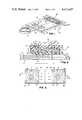
- a device 10 for differentially measuring electrolytescomprises, FIGS.
- each ISEis a generally flat multilayered element comprising adjacent layers 16-20, FIG. 2.
- FIG. 2When a drop of blood serum A or B, FIG. 2, makes contact with layer 16, an ion-selective membrane containing an ionophore and a solvent, the Z.sup.
- Layer 17for example, can be a dried hydrophilic binder containing the salt Z.sup. ⁇ X.sup. ⁇ .
- Layer 18 in such instancesis the X.sup. ⁇ salt of an electrically conductive metal M.sup. ⁇ , and metal M° forms layer 19. Because layer 19 is an electrically conductive layer, a potential can be detected by electrometer 26, FIG. 1, via probes 24 which penetrate into contact with layer 19 at windows 22.
- the flow control meanscomprises bridge 36 that provides means for directing the liquid flow from drops A and B to ISE's 14 and to each other, FIG. 2.
- the bridgein turn comprises two members 38 and 40 spaced apart in the manner described below to form a transport zone 41.
- apertures 28 and 28'are positioned above and adjacent to the respective ISE 14 and 14' to be contacted by the liquid.
- any convenient drop dispensercan supply the drops, either in free-falling form or as drops touched-off from a platform.
- the dropsare dispensed approximately at the same time to insure proper junction formation, as described below.
- members 38 and 40have opposing internal surfaces spaced apart a distance "s" effective to induce capillary flow of liquid between the surfaces and to define the transport zone 41.
- Apertures 27 and 27'are sized to insure that the drops penetrate into the apertures and wet both of these opposing surfaces.
- each surfacebears a pattern of exposed grooves 42 and 44, which can be, for example, sawtooth in shape. Grooves 44 extend from at least the vicinity of aperture 28 to at least the vicinity of aperture 28', and are preferably substantially parallel and straight. Grooves 42 are superimposed over grooves 44 preferably at a positive, that is, non-zero angle "alpha", FIG. 3.
- alphais about 90°, and the grooves are also substantially parallel and straight along their lengths.
- grooves 42 and their ridges 46have a width "w" and thickness "t", respectively, of about 13 microns. The same or different dimensions can be used for grooves 44 and their ridges.
- Grooves 42, FIG. 2,represent a groove pattern as it would appear magnified approximately 700 times.
- Member 38is spaced from member 40 by any suitable means, such as edge walls 54, so that grooves 42 are spaced from grooves 44 the effective distance that provides capillary flow.
- Walls 54can be affixed to member 40 by means such as adhesive.
- at least a portion of the space between grooves 42 and 44is left exposed at one or both of zone edges 56 and 57 of bridge 36, FIG. 1, whereby air can be vented or expelled as liquid menisci advance.
- edges 56 and 57represent an energy barrier to further flow of the liquid. That is, the line of intersection between the edges 56 and 57 and the opposed surfaces represents a discontinuity beyond which capillary flow of the liquid can not proceed. Thus, leakage of the bridge is avoided.
- the two memberscan be welded together at appropriate positions, such as by ultrasonic welding to form bridging studs that space the members apart.
- welding of the two members at pairs of relatively small spots 58, shown on phantom FIG. 3,provides the desired spacing.
- the welding spotscan be widened and located between apertures 27 and 27b' to create a barrier for each wave front with a restricted gating aperture for retarded flow-through.
- the applied dropsnot only penetrate apertures 28 and 28', FIG. 2, as shown by arrows 32, to contact ISE's 14 and 14', they also flow along paths designated by arrows 60 to form two advancing wave fronts 62, FIG. 3, that flow in a predictable manner with a predetermined peripheral wave front configuration. Because grooves 42 and ridges 46 are linear, so are wave fronts 62. Because ridges 46, FIG. 2, are parallel throughout bridge 36, the wave fronts when they meet form a junction 64, FIG. 3, shown in phantom.
- Grooves 42 and 44 and their ridges 46 and 48have a number of dimensions which can be varied depending on the desired rate of flow of a particular liquid, as will be apparent to one skilled in the art. These dimensions are the grooves' width w, the ridges' thickness t and surface spacing s, already mentioned, the depths d 1 and d 2 of grooves 42 and 44, respectively, the included angle beta of ridges 46, and the angle of intersection alpha between the two sets of grooves (FIG. 3). In all cases, capillary flow should be maintained across the opposing surfaces of members 38 and 40 within transport zone 41, and preferably within the grooves 42 and 44, at a rate that is consistent with the intended end use.
- spacing scan be no greater than d 1 and d 2 , that is, the top portions of ridges 46 can contact, not shown, the top portions of ridges 48.
- the width w of grooves 42does partially control, along with depth d 1 or d 2 , the rate of advance of the liquid within those grooves.
- the ratehas been found to vary roughly as an inverse function of the cross-sectional area of the groove that is tansverse to the flow along the length of that groove. That is, the smaller the transverse cross-sectional area of flow through a groove, the faster is the rate of advance of the liquid along that groove, because of capillary action.
- the grooves 42 and 44have uniform, cross-sectional areas different one from the other, the direction of the grooves (measured lengthwise) having the smaller value of that area will be the dominant flow direction.
- the grooves 42 and 44are respectively sized so that grooves 42 fill to their zonal edges 56 first, before junction 64 forms.
- Included angle beta of ridges 46 or 48is preferably between about 10° and about 100°, most preferably about 90°.
- Angle alphacan be varied even to the point of equaling zero.
- apertures 27 and 28should have a spacing from apertures 27' and 28', such as distance "x", FIG. 2, sufficient to insure that each drop starts to spread from its aperture towards the other drop within the transport zone before the other drop reaches that aperture. Otherwise, for example, drop A from aperture 27 will flow into contact with ISE 14' causing contamination, and junction 64 will not form.
- the preferred value of alphais selected to be about 90°.
- the exact value for the lateral spacing of the aperturesdepends on the value of alpha (i.e., how close it is to zero), the size of the grooves, and the surface tension of the liquid under analysis.
- grooves 42 and 44need not be saw-toothed as shown, but can be varied. For example, they can be rounded and ridges 46 can be truncated.
- the groove pattern variables of bridge 36be chosen as follows.
- the effective spacing s between the two surfacescan be varied between about 0.06 mm and about 0.6 mm for best results. Lesser values of s can be used, except that when the separation distance s approaches d 1 plus d 2 , spreading through the zone becomes extremely delayed. Values of s greater than about 0.6 mm can in some cases destroy the capillary effect and thus the control over the wave front shape and rate of movement.
- a preferred range for the width w of the groovesis between about 5 microns and about 5 mm, it being noted that beyond about 5 mm, the rate and direction of spreading becomes so ill-defined as to be insignificantly different from the results achieved by two smooth surfaces.
- Preferred materials for at least the opposing surfaces of members 38 and 40, that is for the surfaces of grooves 42 and 44,are non-fibrous material that are substantially impervious to blood serum.
- examples of such materialsinclude acetates such as cellulose triacetate, cellulose acetate propionate, and cellulose acetate butyrate; polystyrene; polyethylene; polypropylene; ABS plastic; and polycarbonate.
- Such surface materialspermit various chemical coatings to be applied, if desired, for example, surfactants.
- zone 41a primary advantage of the construction of zone 41 as described above is its generally open configuration that nevertheless provides a controlled flow. Such a configuration leaves ample room for the flow of whole blood, unlike devices which utilize porous absorbent bridge means with void volumes less than about 50%. Furthermore, the materials described in the preceding paragraph, by being free of fibers, avoid the possibility of shorting out the ISE's.
- At least one of the opposing surfaces forming the transport zonecan be completely smooth. Parts similar to those previously described bear the same reference numeral to which the distinguishing suffix "a" is appended.
- device 10a and bridge 36a, FIG. 4are generally identical to the device and bridge of the previous embodiment, for example, apertures 27a, 27a', 28a and 28a' provide flow of the two drops to ISE's 14a as described above.
- member 38ais provided with grooves 42a and ridges 46a as before, the opposing member 40a having a substantially smooth surface 70.
- the length of grooves 42acan extend from aperture 27a to aperture 27a', FIG.
- grooves 42 acan be eliminated, not shown, to form a smooth surface, and surface 70 can be retained as a smooth surface or can be grooved as in the embodiment of FIG. 2.
- junction 64awhich forms, FIG. 5b, is characterized by a relatively large width creating a wide diffusion zone that is relatively slow to reach equilibrium. It was thought that such a wide junction 64a would be likely to produce a significant bias in the form of a large and/or varying junction potential. In actuality, however, the electrical properties of ISE's 14a and 14'a are such that such a detrimental junction potential is not readily detectable.
- junction 64amight become significant.
- the embodiment of FIGS. 1-3would be preferred as providing controlled predictable wave front peripheries that join to produce a minimum width junction 64.
- FIG. 6illustrates a currently preferred form of the liquid ingress apertures in exterior member 38b. Parts similar to those previously described bear the same reference numeral to which the distinguishing suffix "b" is appended.
- bridge 36bcomprises upper or exterior member 38b and lower or interior member 40b. Each member has grooves 42b and 44b in its opposing surface, as previously described.
- U.S. application Ser. No. 59,924, filed on July 23, 1979 entitled “Improved Structural Configuration and Method For Transport of a Liquid Drop Through an Ingress Aperture"now U.S. Pat. No. 4,254,083, issued on Mar.
- the apertures through member 38bare preferably formed by a cornered sidewall 80. That is, to drive a drop of liquid from the sidewall of the aperture into the center of the aperture, sidewall 80 is provided with a plurality of corners 82. Because of the surface tension of a deposited drop, such corners act as sites for increasing the centering vectors, thus driving the drops from the edge of the aperture into the aperture center. The fewer the number of corners, the less likely it is a drop will contact a corner and be affected. However, if too many corners are included, the aperture sidewall approaches a cylinder in shape, thus losing the benefit of the corner. Preferably, six corners 82 are utilized such that the aperture has the shape of a hexagon when viewed in plan.
- the aperture 27bcan have a variety of dimensions, but preferably for a drop volume of about 10 ⁇ l, it is about 0.25 cm between flats of the hexagon.
- Aperture 28b of member 40bconveniently is cylindrical as in the previous embodiment, being aligned with aperture 27b as shown.
- the device of the inventionneed not position the ion-flow bridge in a plane parallel to that of the planes of the ISE's nor need there be a total of four apertures through the bridge members.
- An alternate embodimentis illustrated in FIG. 7, wherein parts similar to those previously described bear the same reference numeral to which the distinguishing suffix "c" is appended.
- the liquid communication between the transport zone and the ISE'sdoes not comprise internal apertures through one of the members 38c or 40c. Instead, the transport zone itself provides the communication in that edges 57 of the zone terminate at ion-selective membrane 16c of each ISE 14c and 14'c.
- each dropproceeds as shown by arrows 92 and 94, through apertures 27c and 27c', into the transport zone where capillary flow is controlled by the opposing surfaces of members 38c and 40c, and eventually to layers 16c of the ISE's.
- the opposing surfaces of members 38c and 40 ccan be smooth, as at 70c, or can have grooves such as grooves 42c.
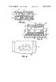
- FIGS. 8 and 9illustrates that fibers can be used in the transport zone. Parts similar to those previously described bear the same reference numerals to which the distinguishing suffix "d" is attached.
- device 10dis the same as device 10a, FIG. 4, and alternatively can have any one of the aforedescribed grooved or smooth configurations for the two opposing surfaces.
- a fibrous material 98is loosely disposed in zone 41d, the fibers being generally parallel and approximately straight, extending from at least aperture 27d to aperture 27d', FIG. 8.
- the fibersare coaxial and non-woven, and occupy no more than about 50% of the volume of zone 41d to permit transport of whole blood.
- the most preferred embodimentis one in which the fibers comprise only 5% of the volume of the zone.
- the alignment of the fibers from aperture 27d to aperture 27d'insures that the pressure loss due to interference to flow between the apertures is minimized.
- the fibersprovide additional capillary transport surfaces to move the liquid from aperture 27d to aperture 27d', without being so closely packed that whole blood cannot be transported as the liquid.
- Such fibersare particularly useful when surfaces 70d and 70d' are low surface energy materials such as polystyrene. Filter tow fibers fabricated from cellulose acetate, for example, can be used.
- the fibersextend out into the space under aperture 27d, so that they are in the flow path from the aperture 27d. As a result, the fibers are contacted by the meniscus 100, FIG. 9, as it comes out of the aperture. In this fashion the fibers help insure that the drop wets both surfaces 70d and 70d' and that flow through zone 41d is initiated.
- the confinement of the fibers to an orientation that is generally perpendicular to the axis of apertures 27d and 27d'is sufficient to insure that no portions of the fibers extend through the lower apertures 28d and 28d' in a manner such as might permit liquid contact with the other ISE and cause a short.
- a third passagewayis provided intermediate the first two as a means for introducing a third liquid.
- the deviceis provided as before with electrodes 14e and 14'e and bridge 36e apertures 27e, 27e' and 28e, 28e' acting as passageways into zone 41e and to the electrodes for the liquid from two drops.
- electrodes 14e and 14'e and bridge 36e apertures 27e, 27e' and 28e, 28e'acting as passageways into zone 41e and to the electrodes for the liquid from two drops.
- gating walls 110extend from surface 70e to surface 70e'.
- Apertures 112is the walls allow restricted flow between apertures 27e and 27e'.
- aperture 120is included in member 38e of the bridge, approximately centered between apertures 27e and 27e'.
- This apertureallows the introduction of a third liquid C, FIG. 11, either before during or after the deposiof the two drops at apertures 27e and 27e'.
- a drop of the third liquidis applied prior to the deposition of the other two drops, and the volume of the third drop together with the restriction created by gating walls 110 act to confine the third liquid to the space between walls 110. Subsequently, the other two drops are applied and the entire zone 41e becomes filled.
- Such an embodimentis particularly useful in applying an equitransferent salt solution of the type described in U.S. Pat. No. 4,053,381, issued on Oct. 11, 1977.
- the salt solutionacts to suppress junction potentials when the two ionic solutions meet within the zone 41e.
- the third solutioncan be added and allowed to dry, coating surfaces 70e and 70e' between the gating walls 110.
- the salts of the coatingthen re-dissolve as the two test drops spread through the zone.
- a gelatinous solution containing the saltscan be introduced through aperture 120 and allowed to "set".
- the flow control meansis bridge 36f comprising upper or exterior member 38f and lower or interior member 40f, FIG. 13, which may or may not be mounted on a larger support (not shown).
- member 40fhas a thickness which renders it self-supporting.
- Each such member 38f and 40fmay or may not have exposed grooves in the opposing surfaces; e.g., grooves 42f, FIG.
- apertures 27f and 27f'are located in member 38f as liquid drop inlet apertures, as described for previous embodiments.
- member 40fno corresponding pair of apertures exists in member 40f.
- the pairs of ISE's 14f 1 , 14f 2 , 14f 3 and 14f 4are disposed along the exposed sides of a capillary transport zone 41f that is formed in the following manner, similar to the embodiment shown in FIG. 7.
- Zone 41fis confined in the vertical direction between members 38f and 40f, and horizontally between ISE pairs 14f 1 etc.
- the pairs of ISE'sare adhered to the side edges of members 38f and 40f by a suitable adhesive, and are disposed so that they also are spaced apart and electrically isolated.
- the ion-selective membranes or substitute layer 16f of the ISE's, FIG. 13,are all directed inwardly towards the zone to permit contact of the liquid as the two drops move through zone 41f from the inlet apertures along paths 130 and 132 (FIG. 12).
- the space between the ISE'scomprises vent apertures that permit air to exit from the zone as indicated by arrow 134, FIG. 13, as the two drops fill the zone.
- conductive layer 19f and support layer 20fcan be formed to extend upwards beyond adjacent layer 18f, FIG. 13.
- each pair of electrodesmust contact the drop deposited at aperture 27f, and the other of each pair must contact the drop deposited at aperture 27f', the pairs are split so that one of electrode pairs 14f 1 , 14f 2 , 14f 3 and 14f 4 is adjacent to aperture 27f and path 130 and the other of each pair is adjacent to aperture 27f' and path 132.
- the sequence of electrodes around each apertureis not critical. Of course, it is preferred that the junction between the two drops form generally in the middle of bridge 36f, between the members of the paired electrodes, as at 64f, FIG. 12. For this reason the grooves, if any, of members 38f and 40f should be designed to insure flow rates that will locate junction 64f as described. Alternatively, a plurality of gating walls, not shown, such as are described in the embodiment of FIG. 10, can be used.
- each of the electrode pairsis specific to the analysis of a different one of the analytes.
- each electrode of any pairis identical to the other of the pair.
- the electrodes for electrode pair 14f 1can be constructed and adapted to detect K.sup. ⁇ , the two electrodes for pair 14f 2 to detect Na.sup. ⁇ , the two electrodes for pair 14f 3 to detect Cl.sup. ⁇ , and the two electrodes for pair 14f 4 to detect HCO 3 .sup. ⁇ .
- the chemistires of the layers of the electrodesare not part of this invention, and comprise generally that described above for ion Z.sup. ⁇ with the appropriate selection of an ionophore for layer 16f.
- layer 16fcontains an ionophore such as valinomycin or one of the others listed in Research Disclosure, Vol. 161, Publication No. 16113, September 1977, 2nd col. of p. 32, published by Industrial Opportunities Limited, Homewell, Havant Hampshire PO91EF, United Kingdom, the contents of which are expressly incorporated herein by reference.
- the ionophoreis preferably methyl monensin, and for HCO 3 .sup. ⁇ the ionophore is preferably 4-octyl trifluoroacetophenone and the solvent is trioctyl propylammonium chloride.
- layers 16 and 17are replaced by an interferant-barrier overcoat layer.
- Such overcoat layercan be, e.g., cellulose acetate containing a polyol.
- the drop of sample to be testedis deposited in one of apertures 27f and 27f' and the reference drop in the other.
- the dropsspread by capillary action along the paths of arrows 130 and 132, contacting the electrodes and eventually each other at junction 64f. Readings can be made by contacting layer 19f of each electrode in a given pair with the probes of an electrometer.
- the spacing between members 38f and 40fshould be as described previously.
- the width of zone 41fe.g., the distance between ISE's 14f 1 and 14f 3 , can be widely varied, preferably between about 5 and 15 mm.
- the total length of zone 41fis a matter of choice.
- Yet another embodiment of the inventionpermits the so-called "absolute" measurement of the analyte activity.
- the embodimentis that of FIGS. 12 and 13, except that one of the eight electrodes 14f 1 through 14f 4 is a common, general reference electrode for all the other electrodes, and each of the other electrodes is an ISE of the type described in previous embodiments, designed to measure with that general reference electrode a particular analyte different from the analytes tested by the others.
- a preferred example of such a general reference electrodeuses a redox couple element of the type described in connection with FIG. 14 of aforesaid U.S. Pat. No. 4,053,381, the details of which are expressly incorporated herein by reference.
- FIGS. 14-16a preferred embodiment of the multi-analyte test device of FIGS. 12 and 13 is illustrated. Parts similar to those previously described bear the same reference numeral to which the distinguishing suffix "g" is applied.
- the device 10gcomprises a frame 12g having opposite side ribs 134, a bridge member 36g and a plurality of ISE's 14g exactly as described for the other multi-analyte embodiments, except that each of the ISE's is located under lower member 40g of the bridge, FIG. 15, rather than at the sides of the transport zone 41g.
- bridge 36ghas been shaped as a horseshoe, with a central portion 136 and two dependent legs 138 and 139, FIG. 14.
- the pairs of ISE'sare conveniently arranged opposite each other on legs 138 and 139, e.g., ISE's 14g 1 aligned opposite each other, 14g 2 opposite each other, and so forth.
- the spacing between adjacent ISE'scan be uniform as shown, or varied.
- Upper member 38g of the bridgeis preferably grooved as at 42g, FIG. 15.
- Gating walls 110gare disposed in zone 41g between each ISE, FIG. 16a, and between apertures 27g and 27g' and those apertures and the first ISE pair 14g 1 , FIG. 14.
- Each gating wallhas an aperture 112g, and serves to join members 38g and 40g in a spaced apart relationship as in previous embodiments.
- the electrometer probescan contact the ISE's at the protruding layer 19g, FIG. 15.
- the flow patterns controlled by gating walls 110g and the distance "Y" between the centers of apertures 27g and 27g', FIG. 14,be such that the two drops meet in portion 136 between the apertures prior to the liquid of either drop contacting the ISE's 14g 1 .
- a specially designed flow aperture 140is included in member 40g, superimposed directly above each ISE, FIGS. 15 and 16. It is this aperture which carries advancing liquid such as blood or blood serum away from zone 41g down into contact with the ISE's. To insure the meniscus of the liquid will completely wet and fill the aperture 140, and therefore the exposed area of the ISE, such aperture preferably has the shape as shown in FIG. 16, namely two parallel sides 142 that close onto one another with two curved surfaces each having a radius of curvature "R 1 " generated from centers of curvature that are spaced apart a distance "x".
- aperture 140can be a rectangle as shown in phantom, FIG. 16.
- the depth of aperture 140 through which the liquid travels to contact the ISE 14 gis preferably 125 microns or less.
- FIG. 16aillustrates the flow pattern from, e.g., aperture 27g.
- the capillary spacing of zone 41gcauses the drop to follow arrow 148 through each of the gating apertures 112g, and a portion of the liquid also follows arrows 149 through apertures 140 into contact with the ISE's 14g 1 , 14g 2 , etc.
- FIG. 17demonstrates how the device of FIGS. 14-16 can be modified to permit two different unknown liquids to be tested on the same test element device 10h, using a common reference liquid. Parts similar to those previously described bear the same reference numeral to which the distinguishing suffix "h" is applied.
- the increased capability of device 10his achieved by a doubling of bridge 36h to include two banks 150 and 152 of paired electrodes 14h, rather than just one, each bank being connected to the other by bridge portion 136h having a third aperture 120h as in the embodiment of FIG. 11.
- Bank 150has paired electrodes 14h 1 , 14h 2 , and 14h 3
- bank 152has paired electrodes 14h 4 and 14h 5 .
- Apertures 27h and 27h', apertures 140h, and gating walls 110hare constructed in the manner described for previous embodiments.
- a drop of blood serum from a first patientis deposited in aperture 27h' while a drop of reference liquid is deposited in aperture 120h and a drop of whole blood from patient A, or of blood serum from patient B, is deposited in aperture 27h.
- the reference liquidserves to keep the two different blood samples apart, and yet the one drop of reference liquid supplies all the reference potential needed for both tests.
- FIGS. 18-22feature a particularly facile form of the invention for rapid and inexpensive manufacture. Parts similar to those previously described bear the same reference numeral to which the distinguishing suffix "k" is attached.
- device 10kFIG. 18, comprises two ISE's 14k constructed as described previously and adhered or otherwise attached to the bottom surface 200 of a frame member 12k, the electrodes being spaced apart to provide electrical isolation.
- the frame memberhas a bridge 36k that is an integral portion thereof, comprising an internal capillary transport zone 41k defined by two opposed, generally smooth surfaces 70k and 70k' spaced apart the distance s, FIG. 19, for providing ionic flow between drops A and B.
- zone 41kextends from zone edges 56k to 56k, and from zone edges 57k to 57k, the latter coinciding with the side surfaces 210 of device 10k.
- either surface 70k or 70k'can alternatively be provided with preferably linear and parallel grooves, not shown. If both surfaces are grooved, the grooves of one surface can be either aligned with or at an angle to those of the other.
- Liquid inlet apertures 27k and 27k'are formed in bridge 36k as before, extending from top surface 214 of the frame member to surface 70k' of the transport zone.
- Apertures 28k and 28k', FIG. 19,constitute the liquid passageways extending from zone 41k to ISE's 14k.
- each of the paired apertures 27k and 28k, and 27k' and 28k'is formed as a single aperture extending from top surface 214 to bottom surface 200, interrupted however by zone 41k.
- a separate vent channel 220is fluidly connected to zone 41k at edges 56k, FIG. 19, each such channel comprising top and bottom surfaces 222 and 224, and side wall surfaces 226 and 228.
- Surfaces 222 and 224are spaced apart a distance greater than distance s, and wall surfaces 228 join surface 70k at intersection edges 56k, at an angle that is sufficient to inhibit movement of the liquid out of zone 41k into channel 220.
- such angleis about 90°.
- apertures 22kextend completely through frame member 12k from top surface 214 to bottom surface 200 and the two electrodes 14k, respectively.
- FIGS. 20a through 20cThe stages of liquid transport using bridge 36k having ungrooved surfaces 70k are indicated in FIGS. 20a through 20c.
- the liquids A and Bsuch as blood serum or whole blood
- FIG. 20aThis is the result of random minor irregularities in the generally smooth surfaces 70k and 70k'.
- edges 56kare reached, FIG. 20b, where the surface tension of the liquid interacts with the barriers created by the edges to halt the movement of the liquid wave fronts. Air that is in the process of being trapped between the two liquid bodies A and B flows out through vent channels 220.
- junction 64kFIG. 20c
- intermixing and junction widthcan be reduced if desired by incorporating grooves into one or both of surfaces 70k and 70k'.
- junction 64ktogether with contact of solutions A and B with ISE's 14k, FIG. 19, completes the electrical circuit via the flow of ions, and an electrometer reading can be made.
- a fibrous materialnot shown, of the type described in the embodiment of FIG. 8, can be loosely disposed within zone 41k.
- one of the vent channels 220can be omitted, the other channel being adequate to allow removal of trapped air.
- the frameneed not be integral with the bridge as in FIG. 18, and yet the bridge can incorporate vent channels as shown in FIG. 18. In such an arrangement the bridge 36 of the device of FIG. 1 would be replaced by just the bridge 36k shown in FIG. 19.
- Still another alternative, not shown,is to ultrasonically seal edges 57k together at each end of bridge 36k, thereby closing zone 41k to the atmosphere except through the apertures extending outwardly from surface 70k'.
- a plurality of small air ventsshould be included extending between surface 70k' and surface 214, disposed between aperture 27k and the side surface 210 adjacent thereto, between aperture 27k' and the side surface 210 adjacent thereto, and between the two apertures 27k and 27k'.
- Such air vents, where used,can be considerably smaller in diameter than apertures 27k and 27k', as they serve only to release trapped air.
- the ventscan be disposed in the shape of an "X", not shown, in surface 214.
- frame member 12kcan be formed as two halves 231, 232 that are symmetric about a plane 234, FIG. 19.
- Such a constructionpermits the use of a process of manufacture such as is shown in FIGS. 21 and 22A-C. That is, to provide a first sheet X of formable material, an extruder 250 ejects sheet X which is passed through two forming rolls 252 and 254. These rolls in turn groove sheet X to the cross-sectional shape shown in FIG. 22A, that is, with depressed surfaces 70k (or 70k'), 222 (or 224), 226 and 228.
- sheet Xis either removed to become a rolled from Y on axle 256, or it is passed continuously under a roller 258 that feeds into position an identical but inverted sheet Y already formed with the cross-sectional shape of FIG. 22B.
- the two sheets X and Yare then secured to each other except for zone 41k and channels 220, FIG. 22C, by pressure rolls 260 and 262, with or without the use of a conventional adhesive, depending on the material of sheets X and Y.
- a flying punch 264forms apertures 22k as well as apertures 27k, 28k, and 27k', 28k', preferably a pair at a time, FIG. 21.
- a flying cutter 266is positioned down-stream of the punch. Meanwhile a conveyor belt 270 carries a pair of preferably identical ISE's 14k into a contacting position below frame member 12k, where the frame member and ISE's are joined such as by an adhesive, not shown, preapplied to the ISE's.
- the aperturescan be formed after individual units are severed, and the ISE's can be attached before the severing of the units.
Landscapes
- Chemical & Material Sciences (AREA)
- Health & Medical Sciences (AREA)
- Life Sciences & Earth Sciences (AREA)
- Chemical Kinetics & Catalysis (AREA)
- General Health & Medical Sciences (AREA)
- Analytical Chemistry (AREA)
- Molecular Biology (AREA)
- Clinical Laboratory Science (AREA)
- Dispersion Chemistry (AREA)
- Hematology (AREA)
- Electrochemistry (AREA)
- Physics & Mathematics (AREA)
- Biochemistry (AREA)
- General Physics & Mathematics (AREA)
- Immunology (AREA)
- Pathology (AREA)
- Investigating Or Analysing Biological Materials (AREA)
Abstract
Description
Claims (5)
Priority Applications (1)
| Application Number | Priority Date | Filing Date | Title |
|---|---|---|---|
| US06/319,568US4413407A (en) | 1980-03-10 | 1981-11-09 | Method for forming an electrode-containing device with capillary transport between electrodes |
Applications Claiming Priority (2)
| Application Number | Priority Date | Filing Date | Title |
|---|---|---|---|
| US06/128,413US4302313A (en) | 1979-07-23 | 1980-03-10 | Electrode-containing device with capillary transport between electrodes |
| US06/319,568US4413407A (en) | 1980-03-10 | 1981-11-09 | Method for forming an electrode-containing device with capillary transport between electrodes |
Related Parent Applications (2)
| Application Number | Title | Priority Date | Filing Date |
|---|---|---|---|
| US5981679AContinuation-In-Part | 1978-10-25 | 1979-07-23 | |
| US06/128,413DivisionUS4302313A (en) | 1979-07-23 | 1980-03-10 | Electrode-containing device with capillary transport between electrodes |
Publications (1)
| Publication Number | Publication Date |
|---|---|
| US4413407Atrue US4413407A (en) | 1983-11-08 |
Family
ID=26826558
Family Applications (1)
| Application Number | Title | Priority Date | Filing Date |
|---|---|---|---|
| US06/319,568Expired - Fee RelatedUS4413407A (en) | 1980-03-10 | 1981-11-09 | Method for forming an electrode-containing device with capillary transport between electrodes |
Country Status (1)
| Country | Link |
|---|---|
| US (1) | US4413407A (en) |
Cited By (65)
| Publication number | Priority date | Publication date | Assignee | Title |
|---|---|---|---|---|
| WO1986000138A1 (en)* | 1984-06-13 | 1986-01-03 | Unilever Plc | Devices for use in chemical test procedures |
| WO1987000286A1 (en)* | 1985-06-27 | 1987-01-15 | Ilex Corporation | Sensor having ion-selective electrodes |
| US4713165A (en)* | 1986-07-02 | 1987-12-15 | Ilex Corporation | Sensor having ion-selective electrodes |
| EP0215419A3 (en)* | 1985-09-18 | 1989-04-19 | Miles Inc. | Volume metering capillary gap device for applying a liquid sample onto a reactive surface |
| US4849340A (en)* | 1987-04-03 | 1989-07-18 | Cardiovascular Diagnostics, Inc. | Reaction system element and method for performing prothrombin time assay |
| US5051237A (en)* | 1988-06-23 | 1991-09-24 | P B Diagnostic Systems, Inc. | Liquid transport system |
| US5141868A (en)* | 1984-06-13 | 1992-08-25 | Internationale Octrooi Maatschappij "Octropa" Bv | Device for use in chemical test procedures |
| US5278079A (en)* | 1992-09-02 | 1994-01-11 | Enzymatics, Inc. | Sealing device and method for inhibition of flow in capillary measuring devices |
| US5628890A (en)* | 1995-09-27 | 1997-05-13 | Medisense, Inc. | Electrochemical sensor |
| WO1997027475A1 (en)* | 1996-01-28 | 1997-07-31 | Meinhard Knoll | Sampling system for analytes which are fluid or in fluids and process for its production |
| US5989917A (en)* | 1996-02-13 | 1999-11-23 | Selfcare, Inc. | Glucose monitor and test strip containers for use in same |
| US5997817A (en)* | 1997-12-05 | 1999-12-07 | Roche Diagnostics Corporation | Electrochemical biosensor test strip |
| WO1999065664A1 (en)* | 1998-06-18 | 1999-12-23 | 3M Innovative Properties Company | Microfluidic articles and method of manufacturing same |
| US6184040B1 (en) | 1998-02-12 | 2001-02-06 | Polaroid Corporation | Diagnostic assay system and method |
| US6287451B1 (en) | 1999-06-02 | 2001-09-11 | Handani Winarta | Disposable sensor and method of making |
| US6290685B1 (en) | 1998-06-18 | 2001-09-18 | 3M Innovative Properties Company | Microchanneled active fluid transport devices |
| US6328930B1 (en) | 1999-02-11 | 2001-12-11 | Polaroid Corporation | Apparatus for performing diagnostic testing |
| US6331715B1 (en) | 1998-10-14 | 2001-12-18 | Polaroid Corporation | Diagnostic assay system and method having a luminescent readout signal |
| US6381846B2 (en) | 1998-06-18 | 2002-05-07 | 3M Innovative Properties Company | Microchanneled active fluid heat exchanger method |
| US20020082540A1 (en)* | 1998-06-18 | 2002-06-27 | 3M Innovative Properties Company | Drug delivery dressing having fluid control film |
| US6431695B1 (en) | 1998-06-18 | 2002-08-13 | 3M Innovative Properties Company | Microstructure liquid dispenser |
| US6454839B1 (en) | 1999-10-19 | 2002-09-24 | 3M Innovative Properties Company | Electrofiltration apparatus |
| US6495373B1 (en) | 1998-10-14 | 2002-12-17 | Polaroid Corporation | Method and apparatus for performing diagnostic tests |
| US6514412B1 (en) | 1998-06-18 | 2003-02-04 | 3M Innovative Properties Company | Microstructured separation device |
| US6524488B1 (en) | 1998-06-18 | 2003-02-25 | 3M Innovative Properties Company | Method of filtering certain particles from a fluid using a depth loading filtration media |
| US20030055360A1 (en)* | 2001-09-05 | 2003-03-20 | Zeleznik Matthew A. | Minimally invasive sensing system for measuring rigidity of anatomical matter |
| US6555060B1 (en) | 1998-10-14 | 2003-04-29 | Polaroid Corporation | Apparatus for performing diagnostic testing |
| US6572745B2 (en) | 2001-03-23 | 2003-06-03 | Virotek, L.L.C. | Electrochemical sensor and method thereof |
| US6576102B1 (en) | 2001-03-23 | 2003-06-10 | Virotek, L.L.C. | Electrochemical sensor and method thereof |
| US20030111357A1 (en)* | 2001-12-13 | 2003-06-19 | Black Murdo M. | Test meter calibration |
| US20030169426A1 (en)* | 2002-03-08 | 2003-09-11 | Peterson Timothy A. | Test member orientation |
| US6641782B1 (en) | 2000-11-15 | 2003-11-04 | Polaroid Corporation | Apparatus for performing diagnostic testing |
| US20040061841A1 (en)* | 2002-07-11 | 2004-04-01 | Black Murdo M. | Enzyme electrodes and method of manufacture |
| US20040178216A1 (en)* | 2003-01-14 | 2004-09-16 | David Brickwood | Sensor dispensing device |
| US20040224369A1 (en)* | 2002-04-19 | 2004-11-11 | Xiaohua Cai | Disposable sensor with enhanced sample port inlet |
| EP1486777A1 (en)* | 2003-06-12 | 2004-12-15 | Bayer Healthcare, LLC | Sensor format and construction method for capillary-filled diagnostic sensor |
| US20050121826A1 (en)* | 2003-12-03 | 2005-06-09 | Kiamars Hajizadeh | Multi-sensor device for motorized meter and methods thereof |
| US20050150763A1 (en)* | 2004-01-09 | 2005-07-14 | Butters Colin W. | Biosensor and method of manufacture |
| US6997343B2 (en) | 2001-11-14 | 2006-02-14 | Hypoguard Limited | Sensor dispensing device |
| US7094354B2 (en) | 2002-12-19 | 2006-08-22 | Bayer Healthcare Llc | Method and apparatus for separation of particles in a microfluidic device |
| US7125711B2 (en) | 2002-12-19 | 2006-10-24 | Bayer Healthcare Llc | Method and apparatus for splitting of specimens into multiple channels of a microfluidic device |
| US7223364B1 (en) | 1999-07-07 | 2007-05-29 | 3M Innovative Properties Company | Detection article having fluid control film |
| WO2007072099A2 (en) | 2005-12-23 | 2007-06-28 | ThalesNano Nanotechnológiai Zrt. | Method of forming a sealed channel of a microfluidic reactor and a microfluidic reactor comprising such channel |
| US7338639B2 (en) | 1997-12-22 | 2008-03-04 | Roche Diagnostics Operations, Inc. | System and method for analyte measurement |
| US7390667B2 (en) | 1997-12-22 | 2008-06-24 | Roche Diagnostics Operations, Inc. | System and method for analyte measurement using AC phase angle measurements |
| US20080173552A1 (en)* | 2005-07-20 | 2008-07-24 | Bayer Healthcare Llc, Diabetes Care Division | Gated Amperometry |
| US20080179197A1 (en)* | 2005-09-30 | 2008-07-31 | Bayer Healthcare Llc, Diabetes Care Division | Gated Voltammetry |
| US7407811B2 (en) | 1997-12-22 | 2008-08-05 | Roche Diagnostics Operations, Inc. | System and method for analyte measurement using AC excitation |
| US7452457B2 (en) | 2003-06-20 | 2008-11-18 | Roche Diagnostics Operations, Inc. | System and method for analyte measurement using dose sufficiency electrodes |
| US7459127B2 (en) | 2002-02-26 | 2008-12-02 | Siemens Healthcare Diagnostics Inc. | Method and apparatus for precise transfer and manipulation of fluids by centrifugal and/or capillary forces |
| US7488601B2 (en) | 2003-06-20 | 2009-02-10 | Roche Diagnostic Operations, Inc. | System and method for determining an abused sensor during analyte measurement |
| US20090068754A1 (en)* | 2006-10-24 | 2009-03-12 | Bayer Healthcare Llc | Transient Decay Amperometry |
| US7556723B2 (en) | 2004-06-18 | 2009-07-07 | Roche Diagnostics Operations, Inc. | Electrode design for biosensor |
| US7569126B2 (en) | 2004-06-18 | 2009-08-04 | Roche Diagnostics Operations, Inc. | System and method for quality assurance of a biosensor test strip |
| US7597793B2 (en) | 2003-06-20 | 2009-10-06 | Roche Operations Ltd. | System and method for analyte measurement employing maximum dosing time delay |
| US7604721B2 (en) | 2003-06-20 | 2009-10-20 | Roche Diagnostics Operations, Inc. | System and method for coding information on a biosensor test strip |
| US7645373B2 (en) | 2003-06-20 | 2010-01-12 | Roche Diagnostic Operations, Inc. | System and method for coding information on a biosensor test strip |
| US7645421B2 (en) | 2003-06-20 | 2010-01-12 | Roche Diagnostics Operations, Inc. | System and method for coding information on a biosensor test strip |
| US7718439B2 (en) | 2003-06-20 | 2010-05-18 | Roche Diagnostics Operations, Inc. | System and method for coding information on a biosensor test strip |
| US8058077B2 (en) | 2003-06-20 | 2011-11-15 | Roche Diagnostics Operations, Inc. | Method for coding information on a biosensor test strip |
| US8071384B2 (en) | 1997-12-22 | 2011-12-06 | Roche Diagnostics Operations, Inc. | Control and calibration solutions and methods for their use |
| US8148164B2 (en) | 2003-06-20 | 2012-04-03 | Roche Diagnostics Operations, Inc. | System and method for determining the concentration of an analyte in a sample fluid |
| US8206565B2 (en) | 2003-06-20 | 2012-06-26 | Roche Diagnostics Operation, Inc. | System and method for coding information on a biosensor test strip |
| US9410917B2 (en) | 2004-02-06 | 2016-08-09 | Ascensia Diabetes Care Holdings Ag | Method of using a biosensor |
| US9933385B2 (en) | 2007-12-10 | 2018-04-03 | Ascensia Diabetes Care Holdings Ag | Method of using an electrochemical test sensor |
Citations (16)
| Publication number | Priority date | Publication date | Assignee | Title |
|---|---|---|---|---|
| US3528903A (en)* | 1968-01-24 | 1970-09-15 | Beckman Instruments Inc | Liquid junction structure |
| CA865849A (en)* | 1971-03-09 | International Business Machines Corporation | Electrode with integral flow channel | |
| US3690836A (en)* | 1966-03-01 | 1972-09-12 | Promoveo | Device for use in the study of chemical and biological reactions and method of making same |
| US3715192A (en)* | 1969-08-12 | 1973-02-06 | Merck Patent Gmbh | Indicator strip |
| US3763422A (en)* | 1971-10-21 | 1973-10-02 | Corning Glass Works | Method and apparatus for electrochemical analysis of small samples of blood |
| US3783696A (en)* | 1971-12-09 | 1974-01-08 | C Coleman | Automatic volume control pipet |
| US3826734A (en)* | 1972-06-26 | 1974-07-30 | Bio Medical Sciences Inc | Apparatus for use in liquid sample analysis |
| US3891507A (en)* | 1974-05-30 | 1975-06-24 | American Cyanamid Co | Organ function test cards |
| CA1008507A (en)* | 1974-03-15 | 1977-04-12 | Avl Ag | Apparatus for the analysis of a liquid sample with a number of electrochemical probes and method of manufacturing the aforesaid apparatus |
| DE2555958A1 (en) | 1975-12-12 | 1977-06-16 | Hartmut Prof Dr Wendt | Capillary electrolytic cell with laminar flow conditions - has grooved counter-electrode with insulating coating, giving high conversion |
| US4046514A (en)* | 1976-11-24 | 1977-09-06 | Miles Laboratories, Inc. | Test device and method for determining a component in a sample |
| US4053381A (en)* | 1976-05-19 | 1977-10-11 | Eastman Kodak Company | Device for determining ionic activity of components of liquid drops |
| US4184936A (en)* | 1978-07-24 | 1980-01-22 | Eastman Kodak Company | Device for determining ionic activity |
| US4273639A (en)* | 1979-06-20 | 1981-06-16 | Eastman Kodak Company | Capillary bridge in apparatus for determining ionic activity |
| US4310399A (en)* | 1979-07-23 | 1982-01-12 | Eastman Kodak Company | Liquid transport device containing means for delaying capillary flow |
| FR2396299B1 (en) | 1977-07-01 | 1983-01-28 | Roehm Gmbh |
- 1981
- 1981-11-09USUS06/319,568patent/US4413407A/ennot_activeExpired - Fee Related
Patent Citations (16)
| Publication number | Priority date | Publication date | Assignee | Title |
|---|---|---|---|---|
| CA865849A (en)* | 1971-03-09 | International Business Machines Corporation | Electrode with integral flow channel | |
| US3690836A (en)* | 1966-03-01 | 1972-09-12 | Promoveo | Device for use in the study of chemical and biological reactions and method of making same |
| US3528903A (en)* | 1968-01-24 | 1970-09-15 | Beckman Instruments Inc | Liquid junction structure |
| US3715192A (en)* | 1969-08-12 | 1973-02-06 | Merck Patent Gmbh | Indicator strip |
| US3763422A (en)* | 1971-10-21 | 1973-10-02 | Corning Glass Works | Method and apparatus for electrochemical analysis of small samples of blood |
| US3783696A (en)* | 1971-12-09 | 1974-01-08 | C Coleman | Automatic volume control pipet |
| US3826734A (en)* | 1972-06-26 | 1974-07-30 | Bio Medical Sciences Inc | Apparatus for use in liquid sample analysis |
| CA1008507A (en)* | 1974-03-15 | 1977-04-12 | Avl Ag | Apparatus for the analysis of a liquid sample with a number of electrochemical probes and method of manufacturing the aforesaid apparatus |
| US3891507A (en)* | 1974-05-30 | 1975-06-24 | American Cyanamid Co | Organ function test cards |
| DE2555958A1 (en) | 1975-12-12 | 1977-06-16 | Hartmut Prof Dr Wendt | Capillary electrolytic cell with laminar flow conditions - has grooved counter-electrode with insulating coating, giving high conversion |
| US4053381A (en)* | 1976-05-19 | 1977-10-11 | Eastman Kodak Company | Device for determining ionic activity of components of liquid drops |
| US4046514A (en)* | 1976-11-24 | 1977-09-06 | Miles Laboratories, Inc. | Test device and method for determining a component in a sample |
| FR2396299B1 (en) | 1977-07-01 | 1983-01-28 | Roehm Gmbh | |
| US4184936A (en)* | 1978-07-24 | 1980-01-22 | Eastman Kodak Company | Device for determining ionic activity |
| US4273639A (en)* | 1979-06-20 | 1981-06-16 | Eastman Kodak Company | Capillary bridge in apparatus for determining ionic activity |
| US4310399A (en)* | 1979-07-23 | 1982-01-12 | Eastman Kodak Company | Liquid transport device containing means for delaying capillary flow |
Non-Patent Citations (1)
| Title |
|---|
| Research Disclosure, vol. 175, Pub. No. 17517, Nov. 1978.* |
Cited By (119)
| Publication number | Priority date | Publication date | Assignee | Title |
|---|---|---|---|---|
| EP0170375A3 (en)* | 1984-06-13 | 1986-02-19 | Unilever Plc | Devices for use in chemical test procedures |
| WO1986000138A1 (en)* | 1984-06-13 | 1986-01-03 | Unilever Plc | Devices for use in chemical test procedures |
| US5141868A (en)* | 1984-06-13 | 1992-08-25 | Internationale Octrooi Maatschappij "Octropa" Bv | Device for use in chemical test procedures |
| AU602868B2 (en)* | 1985-06-27 | 1990-11-01 | Eos Technology Corporation | Sensor having ion-selective electrodes |
| WO1987000286A1 (en)* | 1985-06-27 | 1987-01-15 | Ilex Corporation | Sensor having ion-selective electrodes |
| EP0215419A3 (en)* | 1985-09-18 | 1989-04-19 | Miles Inc. | Volume metering capillary gap device for applying a liquid sample onto a reactive surface |
| US4713165A (en)* | 1986-07-02 | 1987-12-15 | Ilex Corporation | Sensor having ion-selective electrodes |
| US4849340A (en)* | 1987-04-03 | 1989-07-18 | Cardiovascular Diagnostics, Inc. | Reaction system element and method for performing prothrombin time assay |
| US5051237A (en)* | 1988-06-23 | 1991-09-24 | P B Diagnostic Systems, Inc. | Liquid transport system |
| US5278079A (en)* | 1992-09-02 | 1994-01-11 | Enzymatics, Inc. | Sealing device and method for inhibition of flow in capillary measuring devices |
| US5628890A (en)* | 1995-09-27 | 1997-05-13 | Medisense, Inc. | Electrochemical sensor |
| WO1997027475A1 (en)* | 1996-01-28 | 1997-07-31 | Meinhard Knoll | Sampling system for analytes which are fluid or in fluids and process for its production |
| US5989917A (en)* | 1996-02-13 | 1999-11-23 | Selfcare, Inc. | Glucose monitor and test strip containers for use in same |
| US7781639B2 (en) | 1997-08-01 | 2010-08-24 | 3M Innovative Properties Company | Medical article having fluid control film |
| US6420622B1 (en) | 1997-08-01 | 2002-07-16 | 3M Innovative Properties Company | Medical article having fluid control film |
| US20020128578A1 (en)* | 1997-08-01 | 2002-09-12 | 3M Innovative Properties Company | Medical article having fluid control film |
| US7910790B2 (en) | 1997-08-01 | 2011-03-22 | 3M Innovative Properties Company | Medical article having fluid control film |
| USRE42953E1 (en) | 1997-12-05 | 2011-11-22 | Roche Diagnostics Operations, Inc. | Electrochemical biosensor test strip |
| USRE42924E1 (en) | 1997-12-05 | 2011-11-15 | Roche Diagnostics Operations, Inc. | Electrochemical biosensor test strip |
| USRE42560E1 (en) | 1997-12-05 | 2011-07-19 | Roche Diagnostics Operations, Inc. | Electrochemical biosensor test strip |
| US5997817A (en)* | 1997-12-05 | 1999-12-07 | Roche Diagnostics Corporation | Electrochemical biosensor test strip |
| USRE41309E1 (en) | 1997-12-05 | 2010-05-04 | Roche Diagnostics Operations, Inc. | Electrochemical biosensor test strip |
| USRE43815E1 (en) | 1997-12-05 | 2012-11-20 | Roche Diagnostics Operations, Inc. | Electrochemical biosensor test strip |
| US8071384B2 (en) | 1997-12-22 | 2011-12-06 | Roche Diagnostics Operations, Inc. | Control and calibration solutions and methods for their use |
| US7494816B2 (en) | 1997-12-22 | 2009-02-24 | Roche Diagnostic Operations, Inc. | System and method for determining a temperature during analyte measurement |
| US7407811B2 (en) | 1997-12-22 | 2008-08-05 | Roche Diagnostics Operations, Inc. | System and method for analyte measurement using AC excitation |
| US7390667B2 (en) | 1997-12-22 | 2008-06-24 | Roche Diagnostics Operations, Inc. | System and method for analyte measurement using AC phase angle measurements |
| US7338639B2 (en) | 1997-12-22 | 2008-03-04 | Roche Diagnostics Operations, Inc. | System and method for analyte measurement |
| US6184040B1 (en) | 1998-02-12 | 2001-02-06 | Polaroid Corporation | Diagnostic assay system and method |
| US6524488B1 (en) | 1998-06-18 | 2003-02-25 | 3M Innovative Properties Company | Method of filtering certain particles from a fluid using a depth loading filtration media |
| US6381846B2 (en) | 1998-06-18 | 2002-05-07 | 3M Innovative Properties Company | Microchanneled active fluid heat exchanger method |
| US6290685B1 (en) | 1998-06-18 | 2001-09-18 | 3M Innovative Properties Company | Microchanneled active fluid transport devices |
| US6514412B1 (en) | 1998-06-18 | 2003-02-04 | 3M Innovative Properties Company | Microstructured separation device |
| US6431695B1 (en) | 1998-06-18 | 2002-08-13 | 3M Innovative Properties Company | Microstructure liquid dispenser |
| US20020082540A1 (en)* | 1998-06-18 | 2002-06-27 | 3M Innovative Properties Company | Drug delivery dressing having fluid control film |
| US6907921B2 (en) | 1998-06-18 | 2005-06-21 | 3M Innovative Properties Company | Microchanneled active fluid heat exchanger |
| US6867342B2 (en) | 1998-06-18 | 2005-03-15 | 3M Innovative Properties Company | Drug delivery dressing having fluid control film |
| WO1999065664A1 (en)* | 1998-06-18 | 1999-12-23 | 3M Innovative Properties Company | Microfluidic articles and method of manufacturing same |
| US6375871B1 (en) | 1998-06-18 | 2002-04-23 | 3M Innovative Properties Company | Methods of manufacturing microfluidic articles |
| US6761962B2 (en) | 1998-06-18 | 2004-07-13 | 3M Innovative Properties Company | Microfluidic articles |
| US20040081586A1 (en)* | 1998-10-14 | 2004-04-29 | Polaroid Corporation | Method and apparatus for performing diagnostic testing |
| US6331715B1 (en) | 1998-10-14 | 2001-12-18 | Polaroid Corporation | Diagnostic assay system and method having a luminescent readout signal |
| US6495373B1 (en) | 1998-10-14 | 2002-12-17 | Polaroid Corporation | Method and apparatus for performing diagnostic tests |
| US6555060B1 (en) | 1998-10-14 | 2003-04-29 | Polaroid Corporation | Apparatus for performing diagnostic testing |
| US6328930B1 (en) | 1999-02-11 | 2001-12-11 | Polaroid Corporation | Apparatus for performing diagnostic testing |
| US6287451B1 (en) | 1999-06-02 | 2001-09-11 | Handani Winarta | Disposable sensor and method of making |
| US7223364B1 (en) | 1999-07-07 | 2007-05-29 | 3M Innovative Properties Company | Detection article having fluid control film |
| US8197775B2 (en) | 1999-07-07 | 2012-06-12 | 3M Innovative Properties Company | Detection article having fluid control film |
| US6471746B2 (en) | 1999-10-19 | 2002-10-29 | 3M Innovative Properties Company | Electrofiltration process |
| US6454839B1 (en) | 1999-10-19 | 2002-09-24 | 3M Innovative Properties Company | Electrofiltration apparatus |
| US6641782B1 (en) | 2000-11-15 | 2003-11-04 | Polaroid Corporation | Apparatus for performing diagnostic testing |
| US6849216B2 (en) | 2001-03-23 | 2005-02-01 | Virotek, L.L.C. | Method of making sensor |
| US6576102B1 (en) | 2001-03-23 | 2003-06-10 | Virotek, L.L.C. | Electrochemical sensor and method thereof |
| US6572745B2 (en) | 2001-03-23 | 2003-06-03 | Virotek, L.L.C. | Electrochemical sensor and method thereof |
| US20030055360A1 (en)* | 2001-09-05 | 2003-03-20 | Zeleznik Matthew A. | Minimally invasive sensing system for measuring rigidity of anatomical matter |
| US6997343B2 (en) | 2001-11-14 | 2006-02-14 | Hypoguard Limited | Sensor dispensing device |
| US20030111357A1 (en)* | 2001-12-13 | 2003-06-19 | Black Murdo M. | Test meter calibration |
| US7459127B2 (en) | 2002-02-26 | 2008-12-02 | Siemens Healthcare Diagnostics Inc. | Method and apparatus for precise transfer and manipulation of fluids by centrifugal and/or capillary forces |
| US8337775B2 (en) | 2002-02-26 | 2012-12-25 | Siemens Healthcare Diagnostics, Inc. | Apparatus for precise transfer and manipulation of fluids by centrifugal and or capillary forces |
| US20030169426A1 (en)* | 2002-03-08 | 2003-09-11 | Peterson Timothy A. | Test member orientation |
| US6837976B2 (en) | 2002-04-19 | 2005-01-04 | Nova Biomedical Corporation | Disposable sensor with enhanced sample port inlet |
| US20040224369A1 (en)* | 2002-04-19 | 2004-11-11 | Xiaohua Cai | Disposable sensor with enhanced sample port inlet |
| US7250095B2 (en) | 2002-07-11 | 2007-07-31 | Hypoguard Limited | Enzyme electrodes and method of manufacture |
| US20040061841A1 (en)* | 2002-07-11 | 2004-04-01 | Black Murdo M. | Enzyme electrodes and method of manufacture |
| US7094354B2 (en) | 2002-12-19 | 2006-08-22 | Bayer Healthcare Llc | Method and apparatus for separation of particles in a microfluidic device |
| US7125711B2 (en) | 2002-12-19 | 2006-10-24 | Bayer Healthcare Llc | Method and apparatus for splitting of specimens into multiple channels of a microfluidic device |
| US7264139B2 (en) | 2003-01-14 | 2007-09-04 | Hypoguard Limited | Sensor dispensing device |
| US20040178216A1 (en)* | 2003-01-14 | 2004-09-16 | David Brickwood | Sensor dispensing device |
| EP1486777A1 (en)* | 2003-06-12 | 2004-12-15 | Bayer Healthcare, LLC | Sensor format and construction method for capillary-filled diagnostic sensor |
| US20040253367A1 (en)* | 2003-06-12 | 2004-12-16 | Wogoman Frank W. | Sensor format and construction method for capillary-filled diagnostic sensors |
| US7544277B2 (en) | 2003-06-12 | 2009-06-09 | Bayer Healthcare, Llc | Electrochemical test sensors |
| US8859293B2 (en) | 2003-06-20 | 2014-10-14 | Roche Diagnostics Operations, Inc. | Method for determining whether a disposable, dry regent, electrochemical test strip is unsuitable for use |
| US7452457B2 (en) | 2003-06-20 | 2008-11-18 | Roche Diagnostics Operations, Inc. | System and method for analyte measurement using dose sufficiency electrodes |
| US7597793B2 (en) | 2003-06-20 | 2009-10-06 | Roche Operations Ltd. | System and method for analyte measurement employing maximum dosing time delay |
| US7604721B2 (en) | 2003-06-20 | 2009-10-20 | Roche Diagnostics Operations, Inc. | System and method for coding information on a biosensor test strip |
| US7645373B2 (en) | 2003-06-20 | 2010-01-12 | Roche Diagnostic Operations, Inc. | System and method for coding information on a biosensor test strip |
| US7645421B2 (en) | 2003-06-20 | 2010-01-12 | Roche Diagnostics Operations, Inc. | System and method for coding information on a biosensor test strip |
| US8663442B2 (en) | 2003-06-20 | 2014-03-04 | Roche Diagnostics Operations, Inc. | System and method for analyte measurement using dose sufficiency electrodes |
| US7718439B2 (en) | 2003-06-20 | 2010-05-18 | Roche Diagnostics Operations, Inc. | System and method for coding information on a biosensor test strip |
| US8586373B2 (en) | 2003-06-20 | 2013-11-19 | Roche Diagnostics Operations, Inc. | System and method for determining the concentration of an analyte in a sample fluid |
| US8507289B1 (en) | 2003-06-20 | 2013-08-13 | Roche Diagnostics Operations, Inc. | System and method for coding information on a biosensor test strip |
| US7488601B2 (en) | 2003-06-20 | 2009-02-10 | Roche Diagnostic Operations, Inc. | System and method for determining an abused sensor during analyte measurement |
| US7977112B2 (en) | 2003-06-20 | 2011-07-12 | Roche Diagnostics Operations, Inc. | System and method for determining an abused sensor during analyte measurement |
| US8298828B2 (en) | 2003-06-20 | 2012-10-30 | Roche Diagnostics Operations, Inc. | System and method for determining the concentration of an analyte in a sample fluid |
| US8293538B2 (en) | 2003-06-20 | 2012-10-23 | Roche Diagnostics Operations, Inc. | System and method for coding information on a biosensor test strip |
| US8058077B2 (en) | 2003-06-20 | 2011-11-15 | Roche Diagnostics Operations, Inc. | Method for coding information on a biosensor test strip |
| US8206565B2 (en) | 2003-06-20 | 2012-06-26 | Roche Diagnostics Operation, Inc. | System and method for coding information on a biosensor test strip |
| US8148164B2 (en) | 2003-06-20 | 2012-04-03 | Roche Diagnostics Operations, Inc. | System and method for determining the concentration of an analyte in a sample fluid |
| US8083993B2 (en) | 2003-06-20 | 2011-12-27 | Riche Diagnostics Operations, Inc. | System and method for coding information on a biosensor test strip |
| US20050121826A1 (en)* | 2003-12-03 | 2005-06-09 | Kiamars Hajizadeh | Multi-sensor device for motorized meter and methods thereof |
| US20050150763A1 (en)* | 2004-01-09 | 2005-07-14 | Butters Colin W. | Biosensor and method of manufacture |
| US10067082B2 (en) | 2004-02-06 | 2018-09-04 | Ascensia Diabetes Care Holdings Ag | Biosensor for determining an analyte concentration |
| US9410917B2 (en) | 2004-02-06 | 2016-08-09 | Ascensia Diabetes Care Holdings Ag | Method of using a biosensor |
| US7556723B2 (en) | 2004-06-18 | 2009-07-07 | Roche Diagnostics Operations, Inc. | Electrode design for biosensor |
| US8092668B2 (en) | 2004-06-18 | 2012-01-10 | Roche Diagnostics Operations, Inc. | System and method for quality assurance of a biosensor test strip |
| US9410915B2 (en) | 2004-06-18 | 2016-08-09 | Roche Operations Ltd. | System and method for quality assurance of a biosensor test strip |
| US7569126B2 (en) | 2004-06-18 | 2009-08-04 | Roche Diagnostics Operations, Inc. | System and method for quality assurance of a biosensor test strip |
| US8877035B2 (en) | 2005-07-20 | 2014-11-04 | Bayer Healthcare Llc | Gated amperometry methods |
| US20080173552A1 (en)* | 2005-07-20 | 2008-07-24 | Bayer Healthcare Llc, Diabetes Care Division | Gated Amperometry |
| US8425757B2 (en) | 2005-07-20 | 2013-04-23 | Bayer Healthcare Llc | Gated amperometry |
| US20080179197A1 (en)* | 2005-09-30 | 2008-07-31 | Bayer Healthcare Llc, Diabetes Care Division | Gated Voltammetry |
| US9835582B2 (en) | 2005-09-30 | 2017-12-05 | Ascensia Diabetes Care Holdings Ag | Devices using gated voltammetry methods |
| US8647489B2 (en) | 2005-09-30 | 2014-02-11 | Bayer Healthcare Llc | Gated voltammetry devices |
| US8404100B2 (en) | 2005-09-30 | 2013-03-26 | Bayer Healthcare Llc | Gated voltammetry |
| US11435312B2 (en) | 2005-09-30 | 2022-09-06 | Ascensia Diabetes Care Holdings Ag | Devices using gated voltammetry methods |
| US9110013B2 (en) | 2005-09-30 | 2015-08-18 | Bayer Healthcare Llc | Gated voltammetry methods |
| US10670553B2 (en) | 2005-09-30 | 2020-06-02 | Ascensia Diabetes Care Holdings Ag | Devices using gated voltammetry methods |
| WO2007072099A3 (en)* | 2005-12-23 | 2007-09-13 | Thales Nanotechnologiai Zrt | Method of forming a sealed channel of a microfluidic reactor and a microfluidic reactor comprising such channel |
| US7919055B2 (en) | 2005-12-23 | 2011-04-05 | ThalesNano Nanotechnológiai Zrt. | Method of forming a sealed channel of a microfluidic reactor and a microfluidic reactor comprising such channel |
| WO2007072099A2 (en) | 2005-12-23 | 2007-06-28 | ThalesNano Nanotechnológiai Zrt. | Method of forming a sealed channel of a microfluidic reactor and a microfluidic reactor comprising such channel |
| US20090098029A1 (en)* | 2005-12-23 | 2009-04-16 | Daniel Szalay | Method of forming a sealed channel of a microfluidic reactor and a microfluidic reactor comprising such channel |
| US8026104B2 (en) | 2006-10-24 | 2011-09-27 | Bayer Healthcare Llc | Transient decay amperometry |
| US20090068754A1 (en)* | 2006-10-24 | 2009-03-12 | Bayer Healthcare Llc | Transient Decay Amperometry |
| US10190150B2 (en) | 2006-10-24 | 2019-01-29 | Ascensia Diabetes Care Holdings Ag | Determining analyte concentration from variant concentration distribution in measurable species |
| US8470604B2 (en) | 2006-10-24 | 2013-06-25 | Bayer Healthcare Llc | Transient decay amperometry |
| US11091790B2 (en) | 2006-10-24 | 2021-08-17 | Ascensia Diabetes Care Holdings Ag | Determining analyte concentration from variant concentration distribution in measurable species |
| US9005527B2 (en) | 2006-10-24 | 2015-04-14 | Bayer Healthcare Llc | Transient decay amperometry biosensors |
| US9933385B2 (en) | 2007-12-10 | 2018-04-03 | Ascensia Diabetes Care Holdings Ag | Method of using an electrochemical test sensor |
| US10690614B2 (en) | 2007-12-10 | 2020-06-23 | Ascensia Diabetes Care Holdings Ag | Method of using an electrochemical test sensor |
Similar Documents
| Publication | Publication Date | Title |
|---|---|---|
| US4413407A (en) | Method for forming an electrode-containing device with capillary transport between electrodes | |
| US4302313A (en) | Electrode-containing device with capillary transport between electrodes | |
| US4271119A (en) | Capillary transport device having connected transport zones | |
| US4233029A (en) | Liquid transport device and method | |
| US4310399A (en) | Liquid transport device containing means for delaying capillary flow | |
| CA1160863A (en) | Multi-analyte test device | |
| US4906439A (en) | Biological diagnostic device and method of use | |
| US4273639A (en) | Capillary bridge in apparatus for determining ionic activity | |
| US6194224B1 (en) | Diagnostic membrane containing fatty acid sarcosinate surfactant for testing oral fluid | |
| US3715192A (en) | Indicator strip | |
| JPH046905B2 (en) | ||
| KR20010032781A (en) | analytic test element with a capillary canal | |
| US8182747B2 (en) | Test device for analyzing a biological sample liquid | |
| JPH0713205A (en) | Electrophoresis gel plate and electrophoresis gel plate package and method for making the same | |
| EP0010457B1 (en) | Device for determining the activity of an ionic analyte of a liquid | |
| US4336091A (en) | Method of making capillary bridge in apparatus for determining ionic activity | |
| EP0023156A1 (en) | Liquid transport device for controlled liquid flow, and liquid testing device and device for determining activity of an ionic analyte including a liquid transport device | |
| EP0023157B1 (en) | Liquid transport device | |
| US4783251A (en) | Ionic activity measuring device | |
| US4871441A (en) | Ion activity measuring device | |
| US4556474A (en) | Device for determining ionic analyte activity | |
| JPH01105157A (en) | Long-sized matter of slide for biochemical analysis | |
| JPS6293651A (en) | Liquid specimen analyzing instrument | |
| JPS6293652A (en) | Liquid specimen analyzing instrument | |
| JPH0476428B2 (en) |
Legal Events
| Date | Code | Title | Description |
|---|---|---|---|
| MAFP | Maintenance fee payment | Free format text:PAYMENT OF MAINTENANCE FEE, 4TH YEAR, PL 96-517 (ORIGINAL EVENT CODE: M170); ENTITY STATUS OF PATENT OWNER: LARGE ENTITY Year of fee payment:4 | |
| FEPP | Fee payment procedure | Free format text:PAYOR NUMBER ASSIGNED (ORIGINAL EVENT CODE: ASPN); ENTITY STATUS OF PATENT OWNER: LARGE ENTITY | |
| MAFP | Maintenance fee payment | Free format text:PAYMENT OF MAINTENANCE FEE, 8TH YEAR, PL 96-517 (ORIGINAL EVENT CODE: M171); ENTITY STATUS OF PATENT OWNER: LARGE ENTITY Year of fee payment:8 | |
| AS | Assignment | Owner name:CLINICAL DIAGNOSTIC SYSTEMS INC., NEW YORK Free format text:ASSIGNMENT OF ASSIGNORS INTEREST;ASSIGNOR:EASTMAN KODAK COMPANY;REEL/FRAME:007453/0348 Effective date:19950118 | |
| FEPP | Fee payment procedure | Free format text:MAINTENANCE FEE REMINDER MAILED (ORIGINAL EVENT CODE: REM.); ENTITY STATUS OF PATENT OWNER: LARGE ENTITY | |
| FEPP | Fee payment procedure | Free format text:PAYOR NUMBER ASSIGNED (ORIGINAL EVENT CODE: ASPN); ENTITY STATUS OF PATENT OWNER: LARGE ENTITY Free format text:PAYER NUMBER DE-ASSIGNED (ORIGINAL EVENT CODE: RMPN); ENTITY STATUS OF PATENT OWNER: LARGE ENTITY | |
| LAPS | Lapse for failure to pay maintenance fees | ||
| FP | Lapsed due to failure to pay maintenance fee | Effective date:19951108 | |
| STCH | Information on status: patent discontinuation | Free format text:PATENT EXPIRED DUE TO NONPAYMENT OF MAINTENANCE FEES UNDER 37 CFR 1.362 |