US4413339A - Multiple error detecting and correcting system employing Reed-Solomon codes - Google Patents
Multiple error detecting and correcting system employing Reed-Solomon codesDownload PDFInfo
- Publication number
- US4413339A US4413339AUS06/277,060US27706081AUS4413339AUS 4413339 AUS4413339 AUS 4413339AUS 27706081 AUS27706081 AUS 27706081AUS 4413339 AUS4413339 AUS 4413339A
- Authority
- US
- United States
- Prior art keywords
- word
- symbols
- data
- error
- encoding
- Prior art date
- Legal status (The legal status is an assumption and is not a legal conclusion. Google has not performed a legal analysis and makes no representation as to the accuracy of the status listed.)
- Expired - Lifetime
Links
- 208000011580syndromic diseaseDiseases0.000claimsabstractdescription55
- 238000012937correctionMethods0.000claimsabstractdescription29
- 238000012360testing methodMethods0.000claimsabstractdescription19
- 238000012545processingMethods0.000claimsdescription38
- 238000013500data storageMethods0.000claimsdescription27
- 238000012546transferMethods0.000claimsdescription23
- 238000012544monitoring processMethods0.000claims7
- 238000009877renderingMethods0.000claims3
- 238000000034methodMethods0.000description17
- 239000004020conductorSubstances0.000description4
- 230000000694effectsEffects0.000description4
- 230000005540biological transmissionEffects0.000description3
- 230000007547defectEffects0.000description3
- 230000006870functionEffects0.000description3
- 230000006872improvementEffects0.000description3
- 238000007796conventional methodMethods0.000description2
- 230000000875corresponding effectEffects0.000description2
- 238000010586diagramMethods0.000description2
- 230000008569processEffects0.000description2
- 238000011084recoveryMethods0.000description2
- 238000010845search algorithmMethods0.000description2
- 238000010998test methodMethods0.000description2
- 230000003213activating effectEffects0.000description1
- 239000011248coating agentSubstances0.000description1
- 238000000576coating methodMethods0.000description1
- 238000004891communicationMethods0.000description1
- 238000010276constructionMethods0.000description1
- 230000002596correlated effectEffects0.000description1
- 230000001934delayEffects0.000description1
- 238000001514detection methodMethods0.000description1
- 238000005516engineering processMethods0.000description1
- 238000004519manufacturing processMethods0.000description1
- 229910044991metal oxideInorganic materials0.000description1
- 150000004706metal oxidesChemical class0.000description1
- 238000012986modificationMethods0.000description1
- 230000004048modificationEffects0.000description1
- 230000004044responseEffects0.000description1
- 238000012956testing procedureMethods0.000description1
- 230000001131transforming effectEffects0.000description1
Images


Classifications
- H—ELECTRICITY
- H03—ELECTRONIC CIRCUITRY
- H03M—CODING; DECODING; CODE CONVERSION IN GENERAL
- H03M13/00—Coding, decoding or code conversion, for error detection or error correction; Coding theory basic assumptions; Coding bounds; Error probability evaluation methods; Channel models; Simulation or testing of codes
- H03M13/03—Error detection or forward error correction by redundancy in data representation, i.e. code words containing more digits than the source words
- H03M13/05—Error detection or forward error correction by redundancy in data representation, i.e. code words containing more digits than the source words using block codes, i.e. a predetermined number of check bits joined to a predetermined number of information bits
- H03M13/13—Linear codes
- H03M13/15—Cyclic codes, i.e. cyclic shifts of codewords produce other codewords, e.g. codes defined by a generator polynomial, Bose-Chaudhuri-Hocquenghem [BCH] codes
- H03M13/151—Cyclic codes, i.e. cyclic shifts of codewords produce other codewords, e.g. codes defined by a generator polynomial, Bose-Chaudhuri-Hocquenghem [BCH] codes using error location or error correction polynomials
Definitions
- This inventionpertains to systems for detecting and correcting errors in digital data. More specifically, the invention concerns a system and circuit that implement Reed-Solomon codes for detecting and correcting multiple errors in digital data when transmitted between devices of a data processing system.
- Devices of data processing systems and of many communication systemsintercommunicate by transmitting and/or receiving digital data signals. These signals generally are electrical or electromagnetic representations of "ones” and “zeroes” and are transferred through a data channel between the devices in a serial or parallel fashion.
- the electrical subsystems between the origin of the data and the end usertypically constitute the data channel.
- errorssometimes occur. These errors mainly result from inherent or extraneous noise in the data channel.
- a magnetic storage device used in a data processing systemsuch errors can result from defects oftentimes present in the magnetic storage medium, such as, for example, defects in the metal oxide coating.
- Such defectspresent error patterns which may be "bursty" in nature; that is, several contiguous errors may occur when retrieving data from a particular location on the storage medium. To render the storage device useful, these error patterns must be corrected, if at all possible. If uncorrectable, the data is permanently lost.
- a typical encoderproduces parity information, or a checksum word, by sequentially encoding (i.e. mathematically transforming) a fixed number of m-bit symbols, or characters, derived from the original data. Usually, a few bits define a symbol.
- the checksum wordalso comprising a fixed number of m-bit symbols, is then appended to the data symbols thereby to construct the code word.
- the checksum wordin essence, mathematically characterizes the bit patterns of the original data symbols.
- a decoderusing the information contained in the checksum word, examines and manipulates the data bits thereof in a fashion to detect, locate, and/or correct errors occurring therein.
- the checksum word E(x)is generated by dividing (i.e. encoding) the data word d(x) by a (n-k) th order generator polynomial g(x).
- E(x)is the "remainder" of x n-k d(x)/g(x).
- the code word w(x)becomes evenly divisible by the generator polynomial g(x) with a remainder of "zero".
- a correctly received word y(x)also is evenly divisible by g(x) because w(x), by the aforementioned definition, is evenly divisible by g(x). So, one well known procedure for detecting errors upon receipt or retrieval of a word y(x) is to divide it by g(x). If the remainder of y(x)/g(x) is "zero", then w(x) is presumed to have been correctly received. If the remainder of y(x)/g(x) is "non-zero", then an error has occurred and an error correction routine is invoked.
- the nature of the generator polynomial g(x)determines, among other things, the extent and complexity of the error correction routine.
- the generator polynomial g(x)is characterized by having roots ⁇ i which are selected elements of the Galois Field (2 m ). For most m, there is a very large number of generator polynomials g(x). Selecting a proper generator polynomial g(x) for a given application can sometimes be a difficult task.
- Error locations and valuesare respectively calculated from an error location polynomial and an error evaluator polynomial. These polynomials are computed from error syndromes S i which are conventionally obtained by dividing the entire received word y(x) by factors of the generator polynomial g(x). Once the error syndromes S i have been determined, several procedures can be used for computing the error locations and values, the more notable techniques being the Berlekamp-Massey or the Berlekamp decode algorithm for finding the error location polynomial and the Chien's search algorithm for finding error locations. These techniques involve error-location-polynomial determination, root finding for determining the positions of the errors, and error value determination for determining the bit-pattern of the errors.
- generator polynomials g(x)produce code words w(x) that require substantial decoding time thereby making them unsuitable for real time applications, such as during and between the successive transfers of stored code words from successive data sectors of a magnetic disk storage device.
- generator polynomials g(x)that only can be implemented with inordinately complex and expensive circuits. Accordingly, a code providing high efficiency, sufficient correcting capability, rapid decode properties, and a simple and economical circuit implementation is desired.
- an encoderdivides the data word d(x) to produce a code word w(x).
- the Burghard systemuses a nine-stage shift register circuit comprising a feedback path connected to the stages thereof for dividing, by its generator polynomial g(x), a data word symbol as the bits thereof are shifted therethrough. It provides a system that can correct a maximum of two-out-of-eight bits in a symbol that are in error with a coding efficiency of 47% (8 data bits/17 code bits).
- an encoder circuitproduces a code word w(x) which embodies a checksum word E1(x).
- a decoderproduces a second checksum word E2(x) by re-encoding (i.e. decoding) the data portion of the received word y(x), and then compares the previously transmitted checksum word E1(x) with the newly generated checksum word E2(x).
- Different results of comparisons of the checksum words E1(x) and E2(x)uniquely identify a limited number of addresses in a read-only-memory that contain a correspondingly limited number of error patterns in the seventeen-bit code word y(x). To correct errors, these comparisons are correlated with table entries for identifying the locations of the error, and then the bits in the locations in the code word are complemented.
- the feedback shift register circuitis constructed so that the result of the comparison of E1(x) and E2(x) resides in the nine-stage shift register circuitry at the end of the re-encoding of the code word. Due to its short code word (seventeen bits) and low code rate, it is apparent that the Burghard system would be suboptimal for application in magnetic storage devices.
- U.S. Pat. No. 3,668,632 issued to Oldhamimplements a Reed-Solomon (63,52) over GF(2 6 ) error correcting code for use in a digital computer storage system.
- Its code words y(x)are generated by encoding data words d(x) by a generator polynomial g(x) whose roots comprise 6-bit binary symbols that are elements of Galois Field GF(2 6 ) generated by the primitive polynomial x 6 +x+1. With a coding efficiency of approximately 82.5%, it enables correction of five six-bit symbols per code block of sixty-three 6-bit symbols.
- Oldhamuses checksum calculating circuits to divide the entire word y(x) by each factor of the generator polynomial g(x). Other less time consuming measures, such as provided by this invention, could be used for testing the error status of the retrieved code word y(x). Further, Oldham's invention is based on the premise that most errors in computer storage systems occur singularly and that single errors can rapidly be corrected by conventional single error methods (i.e. the single error value V equals the error syndrome S 0 , and the single error location L equals Log [S 1 /S 0 ]). Oldham achieves single error testing by executing a single error correcting routine and re-reading to validate an assumption of a single error.
- U.S. Pat. No. 4,142,174 issued to Chen, et aldescribes a high speed decoding method for Reed-Solomon code words having 8-bit symbols.
- a broad objective of this inventionis to provide an economical system and circuit for efficiently detecting and correcting digital data that has become corrupted during transmission or storage.
- Another objective of this inventionis to provide a time-wise efficient decoding method for detecting and correcting multiple errors occurring in binary data transferred between devices of a data processing system.
- Another objection of this inventionis to provide an error detecting and correcting system for rapidly decoding relatively long code words using a general purpose or special purpose logic processor for computing error syndromes, as opposed to a table look-up technique which is impractical for such code words.
- Another objective of this inventionis to provide a system which rapidly indicates the error status of a retrieved code word in order for immediately indicating the correctness of a retrieved data word and for bypassing the error correction routine when the retrieved data word is correct or otherwise uncorrectable.
- Another objective of this inventionis to provide a method and apparatus for rapidly determining whether a single symbol error exists in a received word so that an abbreviated decode algorithm can be used.
- Another objective of this inventionis to provide an economical circuit having a minimum number of electrical circuit components for rapidly encoding and decoding relatively long code words.
- a further objective of this inventionis to provide a simple electrical circuit that implements a particular encoding scheme possessing high coding efficiency and high correcting power.
- a more specific objective of this inventionis to provide a system arrangement including an error detecting and correcting circuit and a controller therefore in the interconnection between a data processing system and a magnetic storage device thereby to enable real time encoding and decoding of data during its transfer between the data processing system and successive data sectors of a magnetic disk storage device.
- a data processing systemtransmits data words d(x) to a magnetic data storage device.
- a Reed-Solomon encodergenerates a code word w(x) by encoding the data word d(x) thereby to produce a checksum word E(x).
- the code word w(x)is stored in the magnetic disk storage device as a stored word y(x) comprising a data portion c(x) and a checksum portion E1(x) which correspond with d(x) and E(x), respectively.
- the data portion c(x) thereofis simultaneously transferred to a data buffer and encoded with the same Reed-Solomon encoder that was used during the encoding of d(x) to produce a second checksum word E2(x).
- the symbols of both checksum words E1(x) and E2(x)are exclusive "OR'ed" (i.e. compared) to produce an ECC residue R(x) from which error syndromes S i can be computed.
- the residue R(x)is tested within the circuit to determine if it equals "zero". If so, it is assumed that no errors exists.
- an error monitorproduces a first control signal indicating no errors in the symbols of the data portion c(x) of the retrieved code word y(x). The data word c(x) then is immediately transferred to the data processing sytem. If NR equals T+1, the error monitor produces a second control signal indicating that the error is uncorrectable (i.e. contains more than T errors). The data processing system either again reads the stored code word y(x) on one or more occasions and/or abandons further attempts to retrieve the data. If NR is greater than or equal to T+2, the error monitor produces a third control signal indicating that correctable errors probably exist in the data word c(x), in which case, a single error or multiple error correction routine is initiated.
- Another aspect of the inventioncomprises the use of a single-error test procedure for quickly determining whether single errors exist in the data word c(x) when retrieved.
- Single errorscan be corrected with minimal delay in completing the transfer of data to the data processing system.
- the systemtests whether the syndromes relationship S i+1 /S i , for all syndromes S i , is constant. If this condition holds true, a single error is presumed to have occurred and it is immediately corrected by conventional techniques.
- the inventionemploys a Reed-Solomon encoder to produce code words w(x) having 10-bit wide binary symbols from data words d(x) also having 10-bit wide binary symbols wherein the generator polynomial g(x) that encodes the data words is characterized by having roots ⁇ i in the Galois Field (2 10 ) that is generated, in one embodiment, by the primitive polynomial:
- FIG. 1depicts a prior art structure of an error correcting and detecting system over which this invention is an improvement.
- FIG. 2depicts a preferred structure of an error correcting and detecting system constructed in accordance with this invention.
- FIG. 3shows the invention coupled with a data storage facility.
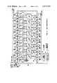
- FIG. 4depicts the preferred Reed-Solomon encoding circuitry that is used in the data processing system of FIG. 3.
- FIGS. 5 and 6depict timing diagrams that illustrate the operation of the encoding circuit of FIG. 4.
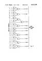
- FIG. 7illustrates a typical one of the feedback multiplier circuits use in the encoding circuit of FIG. 4.
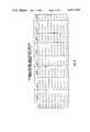
- FIG. 8is a table showing the feedback interconnections for all of the feedback multiplier circuits depicted in FIG. 4 for the primitive polynomial x 10 +x 3 +1.
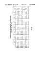
- FIG. 9is a table showing the feedback interconnections for all of the feedback multiplier circuits for the primitive polynomial x 10 +x 7 +1.
- FIGS. 1 and 2illustrate some basic differences between this invention and a prior art system of the type employing a syndrome computer.
- the prior art system depicted in FIG. 1includes a Reed-Solomon encoder 12 that encodes data words d(x) emanating from a data processing device 14 thereby to produce code words w(x) which are transferred to a data storage device 16.
- the code words w(x)are constituted by the data word d(x) and a checksum word E(x) appended thereto.
- a data portion c(x) thereofis transferred to a data buffer 18 and a decoder 19 divides the entire y(x) by the generator polynomial g(x) that was used in the encoder 12 to determine whether it is evenly divisible. If y(x) is evenly divisible, then a NO ERROR signal produced therefrom effects a transfer of the data word c(x) from the data buffer 18 to the data processing system 14. If y(x) is not evenly divisible by g(x), then the syndrome computer divides y(x) by each factor g i (x) of g(x) for producing error syndromes S i .
- the error syndromes S ibear a certain relationship with the location and value of errors occurring in the data word c(x) then present in the data buffer 18.
- the amount of time required for computation of these syndromes S idepends upon the code word length and the error correcting power of the code.
- These syndromesare usually calculated by a special purpose digital computer, such as described in U.S. Pat. No. 4,162,480 issued to Berlekamp, or by using a hardware circuit provided that there are only a few symbols are decoded.
- FIG. 2Several improvements over the prior art system are shown in the inventive embodiment depicted in FIG. 2. Its data processing system 22, encoder 24, data storage device 26 and data buffer 32, operate similar to the corresponding components of FIG. 1. The operation and structure of some of these components are, however, different and do form part of the invention herein. We explain those differences as follows.
- a residue generator 28upon retrieval of a data word y(x) from the data storage device 26, a residue generator 28 produces a residue R(x) by exclusive OR'ing the checksum word E2(x) and the previously stored checksum word E1(x).
- the checksum word E2(x)is produced by again encoding the retrieved data word c(x) by the same encoder 24 that encoded d(x).
- the newly generated checksum word E2(x)equals the "remainder" of x n-k c(x)/g(x).
- error syndromes S icould be computed by dividing R(x) by factors g i (x) of the generator polymonial g(x), and still obtain the same syndromes S i that would be produced by dividing the entire received word y(x) by the factors g i (x).
- an error correcting systememploying means for computing syndromes to find error locations, as opposed to a table look-up procedure. Accordingly, we can implement Reed-Solomon codes that have a much higher error correcting capability, which codes cannot be practically implemented using a table look-up procedure due to the inordinately large table of error patterns.
- checksum word E2(x)is the same as the previously recorded checksum word E1(x)
- the residue R(x)is zero and the received code word y(x) is presumed equal to the transmitted code word w(x) thereby indicating that the received data word c(x) is also equal to the original data word d(x). If E2(x) is different from E1(x), then a transmission error is presumed to have occurred.
- the Reed-Solomon encoder 24also performs the function of the residue generator 28.
- the syndrome computer 30receives and divides the residue R(x) by factors g i (x) of the generator polynomial g(x) for producing the same syndromes S i that would be produced by dividing the entire word y(x) by factors g i (x) of g(x). Production of syndromes from the residue R(x) is much faster since it has fewer terms, e.g. at most, only the number of symbols of the checksum word.
- the syndrome computer 30computes the syndromes S i
- the error location and value computation logic circuit 34receives them and determines the locations and values of the errors in the data word c(x).
- the logic circuit 34supplies the appropriate correction signals to the data buffer 32 for correcting the errors in the retrieved data word c(x).
- the corrected data word c(x)is then transferred from the buffer 32 to the data processing system 22. So, whether the syndrome computer 30 comprises a general purpose logic processor or a special purpose hardware circuit, computation of syndromes S i can be performed much faster from the residue R(x) than by conventional techniques.
- an error monitor 29produces error status control signals in response to a number "NR" of non-zero symbols in the residue R(x). We have found a unique relationship between the number NR of non-zero symbols in the residue R(x) and relative location and number of errors in the word y(x).
- the error monitor 29produces a NO ERROR control signal for indicating no errors in the symbols of the data portion c(x) of the retrieved code word y(x).
- the NO ERROR signalis applied to the data buffer 32 thereby to effect an immediate transfer of the data word c(x) in the buffer 32 to the data processing system without invoking any of the time-consuming decoding or correction routines.
- the error monitor 29If NR equals T+1, the error monitor 29 generates another control signal indicating that c(x) is uncorrectable (i.e. contains more than T errors). This signal is supplied to the syndrome computer 30 to avoid invoking the decoding or correction routines. Instead, a controller for the data storage device attempts to re-read the word y(x) or, after a number of unsuccessful re-read attempts, abandons the task and records a "bad block" message in a status file associated with the storage device. Without the provision of the error monitor 29, it would be necessary to more frequently expend processing time to compute syndromes and the error location polynomial for determining whether y(x) is correctable. Specifically, the degree of the error location polynomial indicates whether the code word y(x) is correctable.
- the error monitor 29produces another control signal indicating that potentially correctable errors exist in the data word c(x), in which case, a single or multiple error correction routine is begun.
- the residue R(x)is "zero"
- c(x)can be immediately transferred from the buffer 32 to the data processing system 22.
- FIG. 3depicts a preferred structure of the error correcting and detecting circuitry that we utilize in a data processing system including data storage means, such as devices 36 through 42.
- the systemincludes an interface device 44 that communicates with other data processing devices, such a central processor unit or a storage bus controller.
- the interface 44operates to transfer storage data to one of the data storage devices 36 through 42 by placing storage data signals, together with other transfer control signals, on an internal data bus 46.
- the transfer control signalsusually identify the source and destination of the storage data signals placed on the bus 46.
- the internal data bus 46comprises a number of parallel conductors for carrying this information to all devices connected thereto.
- the interface 44transmits and places signals representing symbols of a data word d(x) and writing control signals on the bus 46.
- a controller 48responds to the writing control signals by activating a serializer/deserializer (SERDES) circuit 50.
- the SERDES circuit 50converts parallel data into serial data bits which ultimately are transferred to a selected one of the storage devices 36 through 42 under control of a device interface 56.
- the SERDES circuit 50includes a parallel port for receiving 16-bit wide data words over a parallel connection 51 and then transmits these parallel words as a stream of serial data bits from its serial connection 53 to a second SERDES circuit 52.
- the structure of the SERDES circuits 50 and 52are described in a commonly assigned co-pending U.S. application Ser. No. 274,420, entitled CIRCUIT FOR SERIALIZING AND DESERIALIZING DIGITAL DATA by Lih-Jyh Weng and Norman A. Field, incorporated herein.
- the SERDES circuit 52simultaneously performs two functions during a writing operation. First, it supplies 10-bit wide symbols from the serial data stream to the encoder 24 via a parallel connection 55, and second, it passes the serial data bits to the device interface 56 via its serial output connection 57. A predetermined number of the 10-bit wide symbols constitutes a data word d(x). A convenient predetermined number of 10-bit symbols is that which can conveniently be stored in one sector or data block of the data storage devices 36 through 42.
- the specific encoder 24 employedpermits y(x) to include up to one thousand and twenty-three symbols inclusive of the checksum symbols.
- the controller 48halts further inputs of data to the SERDES circuits 50 and 52, and then conditions the Reed-Solomon encoder 54 to shift the 10-bit symbols of the checksum word E(x) then present in the registers thereof to the SERDES circuit 52. This occurs on the next symbol clock cycle while the passage of the last symbol of the data word d(x) through the circuit 52 is occurring and thus enables a time-wise continuous transfer of the symbols that make up the code word w(x).
- the code word w(x)is thus a concatenation of the symbols of d(x) and E(x) and is serially transferred to the interface 56 via the serial connection 57 where it is stored in a selected device 36 through 42.
- the other circuits in the error correcting and detecting systemare not utilized during a writing operation to the data storage devices.
- the code word w(x) that was previously stored in the data storage devicesis retrieved as a code word y(x). It comprises a data word c(x) and a checksum word E1(x), both corresponding to the data word d(x) and the checksum word E(x).
- the controller 48issues an instruction to the interface 56 which supplies, in serial form, the retrieved code word y(x) to the serial input connection 57 of the SERDES circuit 50.
- the SERDES circuit 50like the SERDES circuit 52, then simultaneously performs two operations.
- the encoder 24encodes these 10-bit wide symbols of c(x) to produce a second checksum word E2(x).
- the controller 48enables the stored checksum word E1(x) appended to the data word c(x) to enter into the encoder 24.
- the encoder 24is constructed so that the residue R(x) results from the continued passage of the symbols of E1(x) into the encoder 24 while E2(x) is present therein.
- the encoder 24also performs the function of the residue generator 28 (FIG. 2), the exclusive OR comparator 64, and the error detector 66.
- the retrieved checksum word E1(x)could also have been stored in a checksum data register 62 for comparison with the newly generated E2(x).
- the error detector 66monitors the presence of any non-zero symbols in the residue R(x) and the non-zero symbol counter 77 monitors the number NR of non-zero symbols in the residue R(x) for generating control signals that control the overall operation of the circuit depicted in FIG. 3. If NR is less than the previously identified "T", then the controller 48 immediately tranfers the data word c(x) in the data buffer 58 to the interface device 44 without engaging the error correction routines. If NR equals T+1, a control signal indicating c(x) to be uncorrectable is transmitted to the controller 48 by the error detector 66 via the data bus 46.
- This control signalenables the controller 48 to re-read the uncorrectable data sector without attempting to decode the otherwise uncorrectable errors in the data word c(x). If NR is greater than or equal to T+2, the syndrome computation logic 68 is activated and the error recovery routines are engaged. Error recovery proceeds as follows.
- the order of the residue R(x)is equal to the order of the stored checksum symbols E1(x) (in our preferred embodiment, the order is seventeen) so the syndromes can be computed relatively quickly.
- the error syndromesare produced by dividing y(x) directly by factors g i (x) of the generator polynomial g(x), so a much longer-time results.
- the word y(x)could have as many as one thousand and twenty-three terms.
- the error syndromes S iare generated by a data processing device, such as an LSI-11 processor, manufactured by the assignee hereof. These syndromes could as well be produced by electrical circuit components specially constructed to perform division by factors g i (x) of g(x).
- the single error test logic circuit 70initiates a unique single error test procedure. If only a single error exists, it can quickly be corrected and thereby enable substantially immediate transfer of the data word c(x) from the data buffer 58 to the interface device 44. For a single error, it is well known that:
- Vis the value of the single symbol in y(x) in error. It is also well known that:
- the syndrome computation logic 68 and the single error detecting logic 70use Galois Field log and anti-log tables of all symbols in GF(2 10 ) for producing multiplication and divisions therebetween.
- the use of look-up tables for a limited number of entriesenables determination of products and divisions much faster than other means of performing Galois Field operations.
- This testis made by the logic circuit 70 in a very short period of time so that error location and error value signals can immediately be supplied by the error location and value logic 74 to the data correction logic 76.
- the data correction logic 76places the correction signal together with the appropriate identification signals on the data bus 46 thereby to effect correction of associated c(x) in the data buffer 58. Thereafter, the corrected c(x) is transferred to the interface device 44.
- the error location and value logic 74initiates convention error correction routines, such as the aforementioned Berlekamp-Massey or Berlekamp decode algorithm and the Chien's search algorithm, to locate and evaluate the errors in the data word c(x).
- convention error correction routinessuch as the aforementioned Berlekamp-Massey or Berlekamp decode algorithm and the Chien's search algorithm.
- the aforementioned look-up tablesalso are used to reduce computing time.
- the correction logic circuitthen corrects the errors in the data buffer 58.
- FIGS. 4, 5 and 6together show the Reed-Solomon generator 28 of FIG. 2 and timing diagrams for both writing and reading operations.
- the encoder circuit 28produces code words w(x) by dividing the symbols of a data word d(x) or c(x), as the case may be, received at connection 55 by a generator polynomial g(x) characterized by having roots ⁇ i in the Galois Field GF(2 10 ).
- the Galois Fieldis generated by the primitive polynomial x 10 +x 3 +1.
- Each coefficient of g(x)is applied to two shift register stages in the feedback network 101 to reduce the number of circuit components required therein. After all symbols of the data word d(x) have shifted into the circuit 28, seventeen 10-bit wide symbols of a checksum word E(x) will reside in the stages 104 through 136 thereof. Up to one thousand and six 10-bit data symbols of a data word d(x) can be encoded by the circuit 28.
- the controller 48(FIG. 3) issues a CLEAR signal in order to clear the contents of the stages 104 through 136 of the shift register and the contents of the error detector 192.
- the controllerasserts an IN ENA signal which conditions the input gates 102 to pass 10-bit wide binary symbols of d(x) from the parallel connection 55 of the SERDES circuit 52 to a half-adder circuit 138.
- Half-addersessentially are modulo-two adders and comprise a group of exclusive OR gates, one being associated with each pair of respective bits from the connection 55 and the stage 136.
- the CLOCK pulsesalso are applied to the shift registers 104 through 136 to cause a shift from one stage thereof to a succeeding stage thereof.
- the controller 48also asserts a FB ENA signal to enable the coefficients, i.e. symbols, of d(x) to be successively fed to the stage 1 of the encoder. While being fed to the encoder 24, the coefficients of generator polynomial g(x) are applied to the feedback connections in the feedback circuit 101 so as to effect polynomial division of d(x) by g(x) thereby to produce a remainder; that is, the checksum word E1(x), a lower order polynomial.
- the FB ENA signalconditions the feedback gate circuit 142 to pass the bits of each symbol of d(x) in parallel to each of the multiplier circuits in the feeback circuit 101.
- FIG. 7A typical one of the multiplier circuits representing the coefficients in the feedback circuit 101, such as ⁇ 406 , is depicted in FIG. 7.
- the coefficient ⁇ 406is constructed according to the bit multiplier table shown in FIG. 8.
- the entries of the table in FIG. 8identify the bit positions of the conductor 141 that are applied to the exclusive OR gates as shown in FIG. 7.
- the ten output bits, such as shown in FIG. 7,are then applied to the half-adders 160 through 190 as shown in FIG. 4.
- the Reed-Solomon encoding circuit 100produces n-k checksum symbols E(x) from k 10-bit data signals d(x). After "n" successive symbol CLOCK pulses, the circuit 100 will have produced n-k checksum symbols E(x) at the output gate 194. These checksum symbols will also residue in successive stages x 0 through x 16 of the circuit 100.
- the device interface 56serially transfers a word y(x) that was previously stored as w(x) to the SERDES circuit 50 which picks off sixteen-bit parallel words via connection 51 under control of the controller 48.
- the controller 48stores these 16-bit parallel words in the data buffer 58.
- the SERDES circuit 50also serially passes the retrieved code word y(x) to the SERDES circuit 52 which passes 10-bit wide symbols of y(x) to the encoder 28.
- both the SERDES circuits 50 and 52receives serial data from the device interface 56, in which case, the SERDES circuit 52 is provided with an additional serial input connection 59.
- a CLEAR signal issued by the controller 48clears the stages 104 through 136 of the encoder 28.
- the IN ENA and the FB ENA signalsbecome asserted thereby enabling the encoder 28 to re-encode the symbols of the data word c(x).
- Each assertion of a CLOCK pulseshifts a 10-bit symbol of c(x) into the input gate 102 and through the stages 104 through 136 while the feedback circuit 101 permits the appropriate polynomial division of c(x) by g(x) as previously explained.
- the FB ENA signalis negated thereby to disable the feedback gates 142.
- a continuation of the CLOCK pulsescauses the previously recorded symbols of the checksum word E1(x) that were concatenated with c(x) to continue to enter the encoder 28 through the INPUT GATE 102.
- the k symbols of the data word c(x) that were shifted through the encoding circuit 28produce a second set of checksum symbols E2(x) which, if correct, would be equal to the previously recorded set of checksum symbols E1(x).
- the construction of the feedback circuit 28provides, through the exclusive OR gate 138 and with the FB ENA signal negated, an exclusive OR comparison between the symbols of E2(x) then present in the stages 104 through 136 of the shift register and the symbols of the previously recorded symbols of E1(x) that are being fed to the exclusive OR gate 138.
- the results of this comparisonthat is the residue R(x)
- all seventeen symbols of E1(x)have entered the circuit 28, all seventeen symbols of the residue R(x) will be present in the stages 104 through 136. If the two sets of checksum symbols are equal, then the resulting residue symbols after seventeen successive CLOCK pulses then residing in the shift register would all be zero.
- the residue generator 28serves both as a comparator for comparing the stored checksum symbols E1(x) and the newly generated checksum symbols E2(x), as well as a storage register for residue R(x) after the comparison is made.
- an error detector 192connects to the connection 140. It monitors the comparisons of E1(x) and E2(x) on a symbol-by-symbol basis so that the appropriate control signal can be generated immediately upon generation of the residue R(x).
- the symbols of the residue R(x)also appear in real time at the output gates 192.
- the encoder circuit 28also can be constructed to encode data word d(x) to produce code words w(x) according to a generator polynomial g(x) having roots ⁇ i in the Galois Field GF(2 10 ) generated by the primitive polynomial x 10 +x 7 +1.
- the encoder circuit 28would be similarly constructed, except that the multiplier coefficients of the feedback circuit 101 would apply the bit numbers of the data word symbols on the feedback bus 141 to a multiplier circuit constructed according to the table shown in FIG. 9, instead of FIG. 8. The circuit operation would be the same.
Landscapes
- Physics & Mathematics (AREA)
- Mathematical Physics (AREA)
- Algebra (AREA)
- General Physics & Mathematics (AREA)
- Pure & Applied Mathematics (AREA)
- Probability & Statistics with Applications (AREA)
- Engineering & Computer Science (AREA)
- Theoretical Computer Science (AREA)
- Error Detection And Correction (AREA)
- Detection And Correction Of Errors (AREA)
Abstract
Description
x.sup.10 +x.sup.3 +1,
x.sup.10 +x.sup.7 +1.
S.sub.0 =remainder [y(x)/g.sub.0 (x)]=remainder [R(x)/g.sub.0 (x)],
S.sub.0 =V,
S.sub.1 /S.sub.0 =α.sup.L,
S.sub.i =α.sup.iL V,
S.sub.i+1 /S.sub.i =α.sup.(i+1)L V/α.sup.iL V=α.sup.(i+1)L /α.sup.iL,
α.sup.(i+1)L /α.sup.iL =α.sup.L =constant.
g(x)=x.sup.17 +α.sup.226 x.sup.16 +α.sup.274 x.sup.15 +α.sup.928 x.sup.14
+α.sup.609 x.sup.13 +α.sup.406 x.sup.12 +α.sup.423 x.sup.11 +α.sup.624 x.sup.10
+α.sup.10 x.sup.9 +α.sup.10 x.sup.8 +α.sup.624 x.sup.7 +α.sup.423 x.sup.6
+α.sup.406 x.sup.5 +α.sup.609 x.sup.4 +α.sup.928 x.sup.3 +α.sup.274 x.sup.2 +α.sup.226 x+1.
Claims (19)
Priority Applications (1)
| Application Number | Priority Date | Filing Date | Title |
|---|---|---|---|
| US06/277,060US4413339A (en) | 1981-06-24 | 1981-06-24 | Multiple error detecting and correcting system employing Reed-Solomon codes |
Applications Claiming Priority (1)
| Application Number | Priority Date | Filing Date | Title |
|---|---|---|---|
| US06/277,060US4413339A (en) | 1981-06-24 | 1981-06-24 | Multiple error detecting and correcting system employing Reed-Solomon codes |
Publications (1)
| Publication Number | Publication Date |
|---|---|
| US4413339Atrue US4413339A (en) | 1983-11-01 |
Family
ID=23059239
Family Applications (1)
| Application Number | Title | Priority Date | Filing Date |
|---|---|---|---|
| US06/277,060Expired - LifetimeUS4413339A (en) | 1981-06-24 | 1981-06-24 | Multiple error detecting and correcting system employing Reed-Solomon codes |
Country Status (1)
| Country | Link |
|---|---|
| US (1) | US4413339A (en) |
Cited By (151)
| Publication number | Priority date | Publication date | Assignee | Title |
|---|---|---|---|---|
| US4494234A (en)* | 1982-12-29 | 1985-01-15 | International Business Machines Corporation | On-the-fly multibyte error correcting system |
| US4498175A (en)* | 1982-06-15 | 1985-02-05 | Tokyo Shibaura Denki Kabushiki Kaisha | Error correcting system |
| US4504948A (en)* | 1982-12-29 | 1985-03-12 | International Business Machines Corporation | Syndrome processing unit for multibyte error correcting systems |
| WO1985001369A1 (en)* | 1983-09-19 | 1985-03-28 | Storage Technology Partners Ii | Error detection and correction in an optical storage system |
| WO1985001370A1 (en)* | 1983-09-19 | 1985-03-28 | Storage Technology Partners Ii | Shared encoder/decoder circuits for use with error correction codes of an optical disk system |
| US4541091A (en)* | 1982-06-11 | 1985-09-10 | Hitachi, Ltd. | Code error detection and correction method and apparatus |
| US4567594A (en)* | 1983-06-07 | 1986-01-28 | Burroughs Corporation | Reed-Solomon error detecting and correcting system employing pipelined processors |
| US4569051A (en)* | 1982-08-06 | 1986-02-04 | Sony Corporation | Methods of correcting errors in binary data |
| US4586183A (en)* | 1982-12-17 | 1986-04-29 | Sony Corporation | Correcting errors in binary data |
| US4597083A (en)* | 1984-04-06 | 1986-06-24 | Ampex Corporation | Error detection and correction in digital communication systems |
| US4608456A (en)* | 1983-05-27 | 1986-08-26 | M/A-Com Linkabit, Inc. | Digital audio scrambling system with error conditioning |
| US4633470A (en)* | 1983-09-27 | 1986-12-30 | Cyclotomics, Inc. | Error correction for algebraic block codes |
| US4646303A (en)* | 1983-10-05 | 1987-02-24 | Nippon Gakki Seizo Kabushiki Kaisha | Data error detection and correction circuit |
| US4646312A (en)* | 1984-12-13 | 1987-02-24 | Ncr Corporation | Error detection and correction system |
| US4747103A (en)* | 1985-03-21 | 1988-05-24 | Canon Kabushiki Kaisha | Signal processing apparatus for correcting decoding errors |
| US4777635A (en)* | 1986-08-08 | 1988-10-11 | Data Systems Technology Corp. | Reed-Solomon code encoder and syndrome generator circuit |
| EP0198702A3 (en)* | 1985-04-13 | 1988-10-26 | Sony Corporation | Methods of correcting errors in digital data |
| US4782490A (en)* | 1987-03-16 | 1988-11-01 | Cythera Corporation | Method and a system for multiple error detection and correction |
| US4796110A (en)* | 1986-02-18 | 1989-01-03 | Irwin Magnetic Systems, Inc. | System and method for encoding and storing digital information on magnetic tape |
| US4797848A (en)* | 1986-04-18 | 1989-01-10 | Hughes Aircraft Company | Pipelined bit-serial Galois Field multiplier |
| US4847705A (en)* | 1987-07-07 | 1989-07-11 | Digital Equipment Corporation | Method and apparatus for encoding magnetic disk sector addresses |
| US4873688A (en)* | 1987-10-05 | 1989-10-10 | Idaho Research Foundation | High-speed real-time Reed-Solomon decoder |
| US4914535A (en)* | 1988-01-06 | 1990-04-03 | Digital Equipment Corporation | Synchronization for stored data |
| US4989211A (en)* | 1988-05-12 | 1991-01-29 | Digital Equipment Corporation | Sector mis-synchronization detection method |
| EP0329775A4 (en)* | 1987-08-24 | 1991-09-25 | Digital Equipment Corporation | High bandwidth reed-solomon encoding, decoding and error correcting circuit |
| EP0458468A1 (en)* | 1990-05-09 | 1991-11-27 | Quantum Corporation | A multi-level error correction system |
| US5077737A (en)* | 1989-08-18 | 1991-12-31 | Micron Technology, Inc. | Method and apparatus for storing digital data in off-specification dynamic random access memory devices |
| US5099484A (en)* | 1989-06-09 | 1992-03-24 | Digital Equipment Corporation | Multiple bit error detection and correction system employing a modified Reed-Solomon code incorporating address parity and catastrophic failure detection |
| US5136592A (en)* | 1989-06-28 | 1992-08-04 | Digital Equipment Corporation | Error detection and correction system for long burst errors |
| US5237574A (en)* | 1988-04-08 | 1993-08-17 | Digital Equipment Corporation | Error-resilient information encoding |
| US5241546A (en)* | 1991-02-01 | 1993-08-31 | Quantum Corporation | On-the-fly error correction with embedded digital controller |
| US5265104A (en)* | 1990-11-26 | 1993-11-23 | Digital Equipment Corp. | Data storage system including redundant storage devices |
| US5280488A (en)* | 1990-11-08 | 1994-01-18 | Neal Glover | Reed-Solomon code system employing k-bit serial techniques for encoding and burst error trapping |
| US5335277A (en) | 1981-11-03 | 1994-08-02 | The Personalized Mass Media Corporation | Signal processing appparatus and methods |
| US5373511A (en)* | 1992-05-04 | 1994-12-13 | Motorola, Inc. | Method for decoding a reed solomon encoded signal with inner code and apparatus for doing same |
| WO1995012921A1 (en)* | 1993-11-04 | 1995-05-11 | Cirrus Logic, Inc. | Cyclical redundancy check method and apparatus |
| US5428630A (en)* | 1993-07-01 | 1995-06-27 | Quantum Corp. | System and method for verifying the integrity of data written to a memory |
| US5438577A (en)* | 1991-04-15 | 1995-08-01 | Hitachi, Ltd. | Error correcting system |
| US5444719A (en)* | 1993-01-26 | 1995-08-22 | International Business Machines Corporation | Adjustable error-correction composite Reed-Solomon encoder/syndrome generator |
| US5459742A (en)* | 1992-06-11 | 1995-10-17 | Quantum Corporation | Solid state disk memory using storage devices with defects |
| US5488617A (en)* | 1990-10-16 | 1996-01-30 | U.S. Philips Corporation | Data processor system based on an (n, k) symbol code having symbol error correctibility and plural error mendability |
| US5506958A (en)* | 1993-02-10 | 1996-04-09 | Conner Peripherals, Inc. | Error detection for parallel data transfer between a processor and a peripheral device by comparing regisgers storing a sum of values in bytes of data transferred |
| US5535225A (en)* | 1993-10-12 | 1996-07-09 | Hughes Aircraft Company | Time domain algebraic encoder/decoder |
| US5548775A (en)* | 1993-12-30 | 1996-08-20 | International Business Machines Corporation | System and method for adaptive active monitoring of high speed data streams using finite state machines |
| US5563894A (en)* | 1991-12-10 | 1996-10-08 | Hitachi, Ltd. | Error detecting and correcting method and system |
| WO1997000559A1 (en)* | 1995-06-14 | 1997-01-03 | Quantum Corporation | Dedicated alu architecture for 10-bit reed-solomon error correction module |
| US5602857A (en)* | 1993-09-21 | 1997-02-11 | Cirrus Logic, Inc. | Error correction method and apparatus |
| US5629949A (en)* | 1993-09-21 | 1997-05-13 | Cirrus Logic, Inc. | Error correction verification method and apparatus using CRC check remainders |
| US5642366A (en)* | 1994-07-05 | 1997-06-24 | Adaptec, Inc. | Global parity symbol for interleaved reed-solomon coded data |
| EP0723342A3 (en)* | 1986-09-30 | 1997-08-20 | Canon Kk | Error correction apparatus |
| JP2726902B2 (en) | 1987-08-24 | 1998-03-11 | ディジタル イクイプメント コーポレーション | Wide bandwidth Reed-Solomon encoding, decoding and error correction circuits |
| US5771184A (en)* | 1995-10-12 | 1998-06-23 | Adaptec, Inc. | System and method for solving quadratic equation in galois fields |
| US5771244A (en)* | 1994-03-09 | 1998-06-23 | University Of Southern California | Universal Reed-Solomon coder/encoder |
| US5774648A (en)* | 1996-10-02 | 1998-06-30 | Mitsubishi Semiconductor Of America, Inc. | Address generator for error control system |
| US5787099A (en)* | 1995-10-12 | 1998-07-28 | Adaptec, Inc. | System and method for encoding and decoding data using numerical computations in galois fields |
| WO1998035451A1 (en)* | 1997-01-23 | 1998-08-13 | Quantum Corporation | MODIFIED REED-SOLOMON ERROR CORRECTION SYSTEM USING (w+i+1)-BIT REPRESENTATIONS OF SYMBOLS OF GF(2w+i) |
| US5812438A (en)* | 1995-10-12 | 1998-09-22 | Adaptec, Inc. | Arithmetic logic unit and method for numerical computations in galois fields |
| US5847811A (en)* | 1994-03-25 | 1998-12-08 | Noritsu Koki Co., Ltd. | Photographic film processing apparatus and method of controlling the same |
| US5867640A (en)* | 1993-06-01 | 1999-02-02 | Mti Technology Corp. | Apparatus and method for improving write-throughput in a redundant array of mass storage devices |
| WO1999017454A1 (en)* | 1997-09-30 | 1999-04-08 | Quantum Corporation | Two-level error correction encoder |
| US6219816B1 (en)* | 1997-10-29 | 2001-04-17 | Nec Corporation | Device and method for carrying out Reed-Solomon encoding |
| US20010037484A1 (en)* | 2000-04-10 | 2001-11-01 | Hewlett-Packard Company | Error detection for data storage and transmission |
| US6341362B1 (en) | 1999-04-22 | 2002-01-22 | Vlsi Technology, Inc. | Extended symbol Galois field error correcting device |
| US6405339B1 (en) | 1999-08-31 | 2002-06-11 | International Business Machines Corporation | Parallelized programmable encoder/syndrome generator |
| US20030066010A1 (en)* | 2001-09-28 | 2003-04-03 | Acton John D. | Xor processing incorporating error correction code data protection |
| US20030070133A1 (en)* | 2001-10-05 | 2003-04-10 | Bauman Mitchell A. | Familial correction with non-familial double bit error detection |
| US6553537B1 (en)* | 1998-12-11 | 2003-04-22 | Matsushita Electric Industrial Co., Ltd. | Reed-Solomon decoding apparatus and control method therefor |
| US6574776B1 (en)* | 1999-04-09 | 2003-06-03 | Oak Technology, Inc. | Simultaneous processing for error detection and P-parity ECC encoding |
| WO2003017501A3 (en)* | 2001-08-16 | 2003-10-02 | Broadlight Ltd | System and method for encoding and decoding data utilizing modified reed-solomon codes |
| US6662334B1 (en)* | 1999-02-25 | 2003-12-09 | Adaptec, Inc. | Method and device for performing error correction on ECC data sectors |
| US20040169366A1 (en)* | 2001-05-04 | 2004-09-02 | John Duffell | Method and apparatus for the creation of a self-authenticating document |
| US20050154964A1 (en)* | 2004-01-14 | 2005-07-14 | Andrei Vityaev | Data retrieval from a storage device using a combined error correction and detection approach |
| US20050188292A1 (en)* | 2003-12-23 | 2005-08-25 | International Business Machines Corporation | Method and apparatus for encoding special uncorrectable errors in an error correction code |
| US20060242450A1 (en)* | 2005-04-11 | 2006-10-26 | Li-Lien Lin | Methods and apparatuses for selectively rebuffering and decoding a portion of a data block read from an optical storage medium |
| US20070198626A1 (en)* | 2006-02-20 | 2007-08-23 | Kabushiki Kaisha Toshiba | Semiconductor memory device |
| US20070266291A1 (en)* | 2006-05-15 | 2007-11-15 | Kabushiki Kaisha Toshiba | Semiconductor memory device |
| US20070283208A1 (en)* | 2006-06-01 | 2007-12-06 | International Business Machines Corporation | Systems, methods, and computer program products for providing a two-bit symbol bus error correcting code with bus diagnostic features |
| US20070283229A1 (en)* | 2006-06-01 | 2007-12-06 | International Business Machines Corporation | Systems, methods, and computer program products for providing a two-bit symbol bus error correcting code |
| US20070283223A1 (en)* | 2006-06-01 | 2007-12-06 | International Business Machines Corporation | Systems, methods, and computer program products for providing a two-bit symbol bus error correcting code with all checkbits transferred last |
| US20070283207A1 (en)* | 2006-06-01 | 2007-12-06 | International Business Machines Corporation | Systems, methods, and computer program products for providing a two-bit symbol bus error correcting code with bus timing improvements |
| US20080016432A1 (en)* | 2006-07-12 | 2008-01-17 | Peter Lablans | Error Correction in Multi-Valued (p,k) Codes |
| US20080140740A1 (en)* | 2006-12-08 | 2008-06-12 | Agere Systems Inc. | Systems and methods for processing data sets in parallel |
| US7389466B1 (en)* | 1999-08-12 | 2008-06-17 | Texas Instruments Incorporated | ECC in computer system with associated mass storage device, and method for operating same |
| US20090043951A1 (en)* | 2007-08-06 | 2009-02-12 | Anobit Technologies Ltd. | Programming schemes for multi-level analog memory cells |
| US20090089645A1 (en)* | 2003-05-30 | 2009-04-02 | International Business Machines Corporation | Data storage systems |
| US20090144600A1 (en)* | 2007-11-30 | 2009-06-04 | Anobit Technologies Ltd | Efficient re-read operations from memory devices |
| US20090157964A1 (en)* | 2007-12-16 | 2009-06-18 | Anobit Technologies Ltd. | Efficient data storage in multi-plane memory devices |
| US20090172501A1 (en)* | 2006-03-03 | 2009-07-02 | Ternarylogic Llc | Multi-State Symbol Error Correction in Matrix Based Codes |
| US20100131827A1 (en)* | 2007-05-12 | 2010-05-27 | Anobit Technologies Ltd | Memory device with internal signap processing unit |
| US7769344B1 (en) | 1981-11-03 | 2010-08-03 | Personalized Media Communications, Llc | Signal processing apparatus and methods |
| US20100220509A1 (en)* | 2009-03-01 | 2010-09-02 | Anobit Technologies Ltd | Selective Activation of Programming Schemes in Analog Memory Cell Arrays |
| US20110209029A1 (en)* | 2010-02-19 | 2011-08-25 | Broadcom Corporation | Low complexity error correction using cyclic redundancy check (CRC) |
| US8145984B2 (en) | 2006-10-30 | 2012-03-27 | Anobit Technologies Ltd. | Reading memory cells using multiple thresholds |
| US8151166B2 (en) | 2007-01-24 | 2012-04-03 | Anobit Technologies Ltd. | Reduction of back pattern dependency effects in memory devices |
| US8151163B2 (en) | 2006-12-03 | 2012-04-03 | Anobit Technologies Ltd. | Automatic defect management in memory devices |
| US8156398B2 (en) | 2008-02-05 | 2012-04-10 | Anobit Technologies Ltd. | Parameter estimation based on error correction code parity check equations |
| US8156403B2 (en) | 2006-05-12 | 2012-04-10 | Anobit Technologies Ltd. | Combined distortion estimation and error correction coding for memory devices |
| US8169825B1 (en) | 2008-09-02 | 2012-05-01 | Anobit Technologies Ltd. | Reliable data storage in analog memory cells subjected to long retention periods |
| US20120110415A1 (en)* | 2010-10-27 | 2012-05-03 | Sony Corporation | Decoding apparatus, method, and program |
| US8174857B1 (en) | 2008-12-31 | 2012-05-08 | Anobit Technologies Ltd. | Efficient readout schemes for analog memory cell devices using multiple read threshold sets |
| US8174905B2 (en) | 2007-09-19 | 2012-05-08 | Anobit Technologies Ltd. | Programming orders for reducing distortion in arrays of multi-level analog memory cells |
| US8209588B2 (en) | 2007-12-12 | 2012-06-26 | Anobit Technologies Ltd. | Efficient interference cancellation in analog memory cell arrays |
| US8208304B2 (en) | 2008-11-16 | 2012-06-26 | Anobit Technologies Ltd. | Storage at M bits/cell density in N bits/cell analog memory cell devices, M>N |
| US8230300B2 (en) | 2008-03-07 | 2012-07-24 | Apple Inc. | Efficient readout from analog memory cells using data compression |
| US8234545B2 (en) | 2007-05-12 | 2012-07-31 | Apple Inc. | Data storage with incremental redundancy |
| US8239734B1 (en) | 2008-10-15 | 2012-08-07 | Apple Inc. | Efficient data storage in storage device arrays |
| US8238157B1 (en) | 2009-04-12 | 2012-08-07 | Apple Inc. | Selective re-programming of analog memory cells |
| US8239735B2 (en) | 2006-05-12 | 2012-08-07 | Apple Inc. | Memory Device with adaptive capacity |
| US8248831B2 (en) | 2008-12-31 | 2012-08-21 | Apple Inc. | Rejuvenation of analog memory cells |
| US8259506B1 (en) | 2009-03-25 | 2012-09-04 | Apple Inc. | Database of memory read thresholds |
| US8261159B1 (en) | 2008-10-30 | 2012-09-04 | Apple, Inc. | Data scrambling schemes for memory devices |
| US8270246B2 (en) | 2007-11-13 | 2012-09-18 | Apple Inc. | Optimized selection of memory chips in multi-chips memory devices |
| US8369141B2 (en) | 2007-03-12 | 2013-02-05 | Apple Inc. | Adaptive estimation of memory cell read thresholds |
| US8400858B2 (en) | 2008-03-18 | 2013-03-19 | Apple Inc. | Memory device with reduced sense time readout |
| US8479080B1 (en) | 2009-07-12 | 2013-07-02 | Apple Inc. | Adaptive over-provisioning in memory systems |
| US8482978B1 (en) | 2008-09-14 | 2013-07-09 | Apple Inc. | Estimation of memory cell read thresholds by sampling inside programming level distribution intervals |
| US8493783B2 (en) | 2008-03-18 | 2013-07-23 | Apple Inc. | Memory device readout using multiple sense times |
| US8493781B1 (en) | 2010-08-12 | 2013-07-23 | Apple Inc. | Interference mitigation using individual word line erasure operations |
| US8495465B1 (en) | 2009-10-15 | 2013-07-23 | Apple Inc. | Error correction coding over multiple memory pages |
| US8498151B1 (en) | 2008-08-05 | 2013-07-30 | Apple Inc. | Data storage in analog memory cells using modified pass voltages |
| US8527819B2 (en) | 2007-10-19 | 2013-09-03 | Apple Inc. | Data storage in analog memory cell arrays having erase failures |
| US8570804B2 (en) | 2006-05-12 | 2013-10-29 | Apple Inc. | Distortion estimation and cancellation in memory devices |
| US8572423B1 (en) | 2010-06-22 | 2013-10-29 | Apple Inc. | Reducing peak current in memory systems |
| US8572311B1 (en) | 2010-01-11 | 2013-10-29 | Apple Inc. | Redundant data storage in multi-die memory systems |
| US8595591B1 (en) | 2010-07-11 | 2013-11-26 | Apple Inc. | Interference-aware assignment of programming levels in analog memory cells |
| US8645794B1 (en) | 2010-07-31 | 2014-02-04 | Apple Inc. | Data storage in analog memory cells using a non-integer number of bits per cell |
| US8677054B1 (en) | 2009-12-16 | 2014-03-18 | Apple Inc. | Memory management schemes for non-volatile memory devices |
| US8694814B1 (en) | 2010-01-10 | 2014-04-08 | Apple Inc. | Reuse of host hibernation storage space by memory controller |
| US8694854B1 (en) | 2010-08-17 | 2014-04-08 | Apple Inc. | Read threshold setting based on soft readout statistics |
| US8694853B1 (en) | 2010-05-04 | 2014-04-08 | Apple Inc. | Read commands for reading interfering memory cells |
| US20140122844A1 (en)* | 2012-11-01 | 2014-05-01 | International Business Machines Corporation | Intelligent context management |
| US20140244985A1 (en)* | 2012-11-01 | 2014-08-28 | International Business Machines Corporation | Intelligent context management |
| US8832354B2 (en) | 2009-03-25 | 2014-09-09 | Apple Inc. | Use of host system resources by memory controller |
| US8856475B1 (en) | 2010-08-01 | 2014-10-07 | Apple Inc. | Efficient selection of memory blocks for compaction |
| US8924661B1 (en) | 2009-01-18 | 2014-12-30 | Apple Inc. | Memory system including a controller and processors associated with memory devices |
| US8949684B1 (en) | 2008-09-02 | 2015-02-03 | Apple Inc. | Segmented data storage |
| US9021181B1 (en) | 2010-09-27 | 2015-04-28 | Apple Inc. | Memory management for unifying memory cell conditions by using maximum time intervals |
| EP1990719A3 (en)* | 2007-05-09 | 2015-05-13 | Kabushiki Kaisha Toshiba | Industrial controller |
| US9104580B1 (en) | 2010-07-27 | 2015-08-11 | Apple Inc. | Cache memory for hybrid disk drives |
| US20160285478A1 (en)* | 2015-03-27 | 2016-09-29 | Kabushiki Kaisha Toshiba | Memory controller, semiconductor memory device, and control method for semiconductor memory device |
| US20170075760A1 (en)* | 2015-09-11 | 2017-03-16 | Arm Limited | Error protection |
| US9954553B1 (en)* | 2015-06-05 | 2018-04-24 | Altera Corporation | Circuitry and methods for continuous parallel decoder operation |
| US9997233B1 (en) | 2015-10-08 | 2018-06-12 | Rambus Inc. | Memory module with dynamic stripe width |
| US10439644B2 (en) | 2015-07-14 | 2019-10-08 | Western Digital Technologies, Inc. | Error locator polynomial decoder and method |
| USRE47642E1 (en) | 1981-11-03 | 2019-10-08 | Personalized Media Communications LLC | Signal processing apparatus and methods |
| US10461777B2 (en)* | 2015-07-14 | 2019-10-29 | Western Digital Technologies, Inc. | Error locator polynomial decoder and method |
| US10572189B2 (en) | 2016-11-04 | 2020-02-25 | Sandisk Technologies Llc | Method and decoder to adjust an error locator polynomial based on an error parity |
| US11362678B2 (en) | 2011-12-30 | 2022-06-14 | Streamscale, Inc. | Accelerated erasure coding system and method |
| US11500723B2 (en) | 2011-12-30 | 2022-11-15 | Streamscale, Inc. | Using parity data for concurrent data authentication, correction, compression, and encryption |
| US11556416B2 (en) | 2021-05-05 | 2023-01-17 | Apple Inc. | Controlling memory readout reliability and throughput by adjusting distance between read thresholds |
| US11847342B2 (en) | 2021-07-28 | 2023-12-19 | Apple Inc. | Efficient transfer of hard data and confidence levels in reading a nonvolatile memory |
Citations (18)
| Publication number | Priority date | Publication date | Assignee | Title |
|---|---|---|---|---|
| US3533067A (en)* | 1967-06-15 | 1970-10-06 | Mitre Corp | Error correcting digital coding and decoding apparatus |
| US3648236A (en)* | 1970-04-20 | 1972-03-07 | Bell Telephone Labor Inc | Decoding method and apparatus for bose-chaudhuri-hocquenghem codes |
| US3668632A (en)* | 1969-02-13 | 1972-06-06 | Ibm | Fast decode character error detection and correction system |
| US3714629A (en)* | 1971-06-01 | 1973-01-30 | Ibm | Double error correcting method and system |
| US3801955A (en)* | 1971-12-13 | 1974-04-02 | Honeywell Inf Systems | Cyclic code encoder/decoder |
| US3859630A (en)* | 1973-01-29 | 1975-01-07 | Burroughs Corp | Apparatus for detecting and correcting errors in digital information organized into a parallel format by use of cyclic polynomial error detecting and correcting codes |
| US3868632A (en)* | 1972-11-15 | 1975-02-25 | Ibm | Plural channel error correcting apparatus and methods |
| US3913068A (en)* | 1974-07-30 | 1975-10-14 | Ibm | Error correction of serial data using a subfield code |
| US3983536A (en)* | 1974-07-04 | 1976-09-28 | The Marconi Company Limited | Data signal handling arrangements |
| US4030067A (en)* | 1975-12-29 | 1977-06-14 | Honeywell Information Systems, Inc. | Table lookup direct decoder for double-error correcting (DEC) BCH codes using a pair of syndromes |
| US4059825A (en)* | 1976-10-12 | 1977-11-22 | Greene Edward P | Burst/slip correction decoder and method |
| US4089063A (en)* | 1976-04-12 | 1978-05-09 | Fujitsu Limited | Memory apparatus with defective modules |
| US4099160A (en)* | 1976-07-15 | 1978-07-04 | International Business Machines Corporation | Error location apparatus and methods |
| US4117458A (en)* | 1977-03-04 | 1978-09-26 | Grumman Aerospace Corporation | High speed double error correction plus triple error detection system |
| US4142174A (en)* | 1977-08-15 | 1979-02-27 | International Business Machines Corporation | High speed decoding of Reed-Solomon codes |
| US4162480A (en)* | 1977-01-28 | 1979-07-24 | Cyclotomics, Inc. | Galois field computer |
| US4320510A (en)* | 1979-01-31 | 1982-03-16 | Tokyo Shibaura Denki Kabushiki Kaisha | Error data correcting system |
| US4360916A (en)* | 1979-12-31 | 1982-11-23 | Ncr Canada Ltd.-Ncr Canada Ltee. | Method and apparatus for providing for two bits-error detection and correction |
- 1981
- 1981-06-24USUS06/277,060patent/US4413339A/ennot_activeExpired - Lifetime
Patent Citations (18)
| Publication number | Priority date | Publication date | Assignee | Title |
|---|---|---|---|---|
| US3533067A (en)* | 1967-06-15 | 1970-10-06 | Mitre Corp | Error correcting digital coding and decoding apparatus |
| US3668632A (en)* | 1969-02-13 | 1972-06-06 | Ibm | Fast decode character error detection and correction system |
| US3648236A (en)* | 1970-04-20 | 1972-03-07 | Bell Telephone Labor Inc | Decoding method and apparatus for bose-chaudhuri-hocquenghem codes |
| US3714629A (en)* | 1971-06-01 | 1973-01-30 | Ibm | Double error correcting method and system |
| US3801955A (en)* | 1971-12-13 | 1974-04-02 | Honeywell Inf Systems | Cyclic code encoder/decoder |
| US3868632A (en)* | 1972-11-15 | 1975-02-25 | Ibm | Plural channel error correcting apparatus and methods |
| US3859630A (en)* | 1973-01-29 | 1975-01-07 | Burroughs Corp | Apparatus for detecting and correcting errors in digital information organized into a parallel format by use of cyclic polynomial error detecting and correcting codes |
| US3983536A (en)* | 1974-07-04 | 1976-09-28 | The Marconi Company Limited | Data signal handling arrangements |
| US3913068A (en)* | 1974-07-30 | 1975-10-14 | Ibm | Error correction of serial data using a subfield code |
| US4030067A (en)* | 1975-12-29 | 1977-06-14 | Honeywell Information Systems, Inc. | Table lookup direct decoder for double-error correcting (DEC) BCH codes using a pair of syndromes |
| US4089063A (en)* | 1976-04-12 | 1978-05-09 | Fujitsu Limited | Memory apparatus with defective modules |
| US4099160A (en)* | 1976-07-15 | 1978-07-04 | International Business Machines Corporation | Error location apparatus and methods |
| US4059825A (en)* | 1976-10-12 | 1977-11-22 | Greene Edward P | Burst/slip correction decoder and method |
| US4162480A (en)* | 1977-01-28 | 1979-07-24 | Cyclotomics, Inc. | Galois field computer |
| US4117458A (en)* | 1977-03-04 | 1978-09-26 | Grumman Aerospace Corporation | High speed double error correction plus triple error detection system |
| US4142174A (en)* | 1977-08-15 | 1979-02-27 | International Business Machines Corporation | High speed decoding of Reed-Solomon codes |
| US4320510A (en)* | 1979-01-31 | 1982-03-16 | Tokyo Shibaura Denki Kabushiki Kaisha | Error data correcting system |
| US4360916A (en)* | 1979-12-31 | 1982-11-23 | Ncr Canada Ltd.-Ncr Canada Ltee. | Method and apparatus for providing for two bits-error detection and correction |
Non-Patent Citations (3)
| Title |
|---|
| Berlekamp, Elwyn R.; The Technology of Error-Correcting Codes; The Proceedings of the IEEE, vol. 68, No. 5, May 1980, pp. 564-593.* |
| Lin, Shu; An Introduction to Error-Correcting Codes, Prentice Hall; Chapter 6, pp. 112-135.* |
| Peterson, W. Wesley and Weldon, E. J. Jr.; Error Correcting Codes, pp. 269-304.* |
Cited By (303)
| Publication number | Priority date | Publication date | Assignee | Title |
|---|---|---|---|---|
| US9043859B1 (en) | 1981-11-02 | 2015-05-26 | Personalized Media Communications, Llc | Signal processing apparatus and methods |
| US8640184B1 (en) | 1981-11-03 | 2014-01-28 | Personalized Media Communications, Llc | Signal processing apparatus and methods |
| US7817208B1 (en) | 1981-11-03 | 2010-10-19 | Personalized Media Communications, Llc | Signal processing apparatus and methods |
| US8395707B1 (en) | 1981-11-03 | 2013-03-12 | Personalized Media Communications LLC | Signal processing apparatus and methods |
| US8555310B1 (en) | 1981-11-03 | 2013-10-08 | Personalized Media Communications, Llc | Signal processing apparatus and methods |
| US8559635B1 (en) | 1981-11-03 | 2013-10-15 | Personalized Media Communications, L.L.C. | Signal processing apparatus and methods |
| US8558950B1 (en) | 1981-11-03 | 2013-10-15 | Personalized Media Communications LLC | Signal processing apparatus and methods |
| US8566868B1 (en) | 1981-11-03 | 2013-10-22 | Personalized Media Communications, L.L.C. | Signal processing apparatus and methods |
| US8572671B1 (en) | 1981-11-03 | 2013-10-29 | Personalized Media Communications LLC | Signal processing apparatus and methods |
| US8584162B1 (en) | 1981-11-03 | 2013-11-12 | Personalized Media Communications LLC | Signal processing apparatus and methods |
| US8587720B1 (en) | 1981-11-03 | 2013-11-19 | Personalized Media Communications LLC | Signal processing apparatus and methods |
| US8112782B1 (en) | 1981-11-03 | 2012-02-07 | Personalized Media Communications, Llc | Signal processing apparatus and methods |
| US8060903B1 (en) | 1981-11-03 | 2011-11-15 | Personalized Media PMC Communications, L.L.C. | Signal processing apparatus and methods |
| US8046791B1 (en) | 1981-11-03 | 2011-10-25 | Personalized Media Communications, Llc | Signal processing apparatus and methods |
| US8601528B1 (en) | 1981-11-03 | 2013-12-03 | Personalized Media Communications, L.L.C. | Signal processing apparatus and methods |
| US7992169B1 (en) | 1981-11-03 | 2011-08-02 | Personalized Media Communications LLC | Signal processing apparatus and methods |
| US8607296B1 (en) | 1981-11-03 | 2013-12-10 | Personalized Media Communications LLC | Signal processing apparatus and methods |
| US7953223B1 (en) | 1981-11-03 | 2011-05-31 | Personalized Media Communications, L.L.C. | Signal processing apparatus and methods |
| US7940931B1 (en) | 1981-11-03 | 2011-05-10 | Personalized Media Communications LLC | Signal processing apparatus and methods |
| US8613034B1 (en) | 1981-11-03 | 2013-12-17 | Personalized Media Communications, Llc | Signal processing apparatus and methods |
| US7926084B1 (en) | 1981-11-03 | 2011-04-12 | Personalized Media Communications LLC | Signal processing apparatus and methods |
| US7908638B1 (en) | 1981-11-03 | 2011-03-15 | Personalized Media Communications LLC | Signal processing apparatus and methods |
| US7889865B1 (en) | 1981-11-03 | 2011-02-15 | Personalized Media Communications, L.L.C. | Signal processing apparatus and methods |
| US7797717B1 (en) | 1981-11-03 | 2010-09-14 | Personalized Media Communications, Llc | Signal processing apparatus and methods |
| US7805748B1 (en) | 1981-11-03 | 2010-09-28 | Personalized Media Communications, Llc | Signal processing apparatus and methods |
| US7764685B1 (en) | 1981-11-03 | 2010-07-27 | Personalized Media Communications, L.L.C. | Signal processing apparatus and methods |
| US7865920B1 (en) | 1981-11-03 | 2011-01-04 | Personalized Media Communications LLC | Signal processing apparatus and methods |
| US7861278B1 (en) | 1981-11-03 | 2010-12-28 | Personalized Media Communications, Llc | Signal processing apparatus and methods |
| US7860131B1 (en) | 1981-11-03 | 2010-12-28 | Personalized Media Communications, Llc | Signal processing apparatus and methods |
| US7860249B1 (en) | 1981-11-03 | 2010-12-28 | Personalized Media Communications LLC | Signal processing apparatus and methods |
| US7861263B1 (en) | 1981-11-03 | 2010-12-28 | Personalized Media Communications, Llc | Signal processing apparatus and methods |
| US7856649B1 (en) | 1981-11-03 | 2010-12-21 | Personalized Media Communications, Llc | Signal processing apparatus and methods |
| US7856650B1 (en) | 1981-11-03 | 2010-12-21 | Personalized Media Communications, Llc | Signal processing apparatus and methods |
| US7849480B1 (en) | 1981-11-03 | 2010-12-07 | Personalized Media Communications LLC | Signal processing apparatus and methods |
| US7849493B1 (en) | 1981-11-03 | 2010-12-07 | Personalized Media Communications, Llc | Signal processing apparatus and methods |
| US7849479B1 (en) | 1981-11-03 | 2010-12-07 | Personalized Media Communications, Llc | Signal processing apparatus and methods |
| US5335277A (en) | 1981-11-03 | 1994-08-02 | The Personalized Mass Media Corporation | Signal processing appparatus and methods |
| US7844995B1 (en) | 1981-11-03 | 2010-11-30 | Personalized Media Communications, Llc | Signal processing apparatus and methods |
| US7840976B1 (en) | 1981-11-03 | 2010-11-23 | Personalized Media Communications, Llc | Signal processing apparatus and methods |
| US7836480B1 (en) | 1981-11-03 | 2010-11-16 | Personalized Media Communications, Llc | Signal processing apparatus and methods |
| US7830925B1 (en) | 1981-11-03 | 2010-11-09 | Personalized Media Communications, Llc | Signal processing apparatus and methods |
| US7831204B1 (en) | 1981-11-03 | 2010-11-09 | Personalized Media Communications, Llc | Signal processing apparatus and methods |
| US7827587B1 (en) | 1981-11-03 | 2010-11-02 | Personalized Media Communications, Llc | Signal processing apparatus and methods |
| US7827586B1 (en) | 1981-11-03 | 2010-11-02 | Personalized Media Communications, Llc | Signal processing apparatus and methods |
| US7823175B1 (en) | 1981-11-03 | 2010-10-26 | Personalized Media Communications LLC | Signal processing apparatus and methods |
| US7818778B1 (en) | 1981-11-03 | 2010-10-19 | Personalized Media Communications, Llc | Signal processing apparatus and methods |
| US8191091B1 (en) | 1981-11-03 | 2012-05-29 | Personalized Media Communications, Llc | Signal processing apparatus and methods |
| US7818776B1 (en) | 1981-11-03 | 2010-10-19 | Personalized Media Communications, Llc | Signal processing apparatus and methods |
| US7818777B1 (en) | 1981-11-03 | 2010-10-19 | Personalized Media Communications, Llc | Signal processing apparatus and methods |
| US7818761B1 (en) | 1981-11-03 | 2010-10-19 | Personalized Media Communications, Llc | Signal processing apparatus and methods |
| US7814526B1 (en) | 1981-11-03 | 2010-10-12 | Personalized Media Communications, Llc | Signal processing apparatus and methods |
| US7810115B1 (en) | 1981-11-03 | 2010-10-05 | Personalized Media Communications, Llc | Signal processing apparatus and methods |
| US7864248B1 (en) | 1981-11-03 | 2011-01-04 | Personalized Media Communications, Llc | Signal processing apparatus and methods |
| US7805738B1 (en) | 1981-11-03 | 2010-09-28 | Personalized Media Communications, Llc | Signal processing apparatus and methods |
| US7805749B1 (en) | 1981-11-03 | 2010-09-28 | Personalized Media Communications, Llc | Signal processing apparatus and methods |
| US7801304B1 (en) | 1981-11-03 | 2010-09-21 | Personalized Media Communications, Llc | Signal processing apparatus and methods |
| US7870581B1 (en) | 1981-11-03 | 2011-01-11 | Personalized Media Communications, Llc | Signal processing apparatus and methods |
| US7793332B1 (en) | 1981-11-03 | 2010-09-07 | Personalized Media Communications, Llc | Signal processing apparatus and methods |
| US8621547B1 (en) | 1981-11-03 | 2013-12-31 | Personalized Media Communications, Llc | Signal processing apparatus and methods |
| US7784082B1 (en) | 1981-11-03 | 2010-08-24 | Personalized Media Communications, Llc | Signal processing apparatus and methods |
| US7783252B1 (en) | 1981-11-03 | 2010-08-24 | Personalized Media Communications, Llc | Signal processing apparatus and methods |
| US7774809B1 (en) | 1981-11-03 | 2010-08-10 | Personalized Media Communications, Llc | Signal processing apparatus and method |
| US7769344B1 (en) | 1981-11-03 | 2010-08-03 | Personalized Media Communications, Llc | Signal processing apparatus and methods |
| US7769170B1 (en) | 1981-11-03 | 2010-08-03 | Personalized Media Communications, Llc | Signal processing apparatus and methods |
| US7864956B1 (en) | 1981-11-03 | 2011-01-04 | Personalized Media Communications, Llc | Signal processing apparatus and methods |
| US7761890B1 (en) | 1981-11-03 | 2010-07-20 | Personalized Media Communications, Llc | Signal processing apparatus and methods |
| US8635644B1 (en) | 1981-11-03 | 2014-01-21 | Personalized Media Communications LLC | Signal processing apparatus and methods |
| US5887243A (en) | 1981-11-03 | 1999-03-23 | Personalized Media Communications, L.L.C. | Signal processing apparatus and methods |
| US7752649B1 (en) | 1981-11-03 | 2010-07-06 | Personalized Media Communications, Llc | Signal processing apparatus and methods |
| US7752650B1 (en) | 1981-11-03 | 2010-07-06 | Personalized Media Communications, Llc | Signal processing apparatus and methods |
| US7747217B1 (en) | 1981-11-03 | 2010-06-29 | Personalized Media Communications, Llc | Signal processing apparatus and methods |
| USRE48682E1 (en) | 1981-11-03 | 2021-08-10 | Personalized Media Communications LLC | Providing subscriber specific content in a network |
| USRE48633E1 (en) | 1981-11-03 | 2021-07-06 | Personalized Media Communications LLC | Reprogramming of a programmable device of a specific version |
| USRE48565E1 (en) | 1981-11-03 | 2021-05-18 | Personalized Media Communications LLC | Providing a subscriber specific solution in a computer network |
| USRE48484E1 (en) | 1981-11-03 | 2021-03-23 | Personalized Media Communications, Llc | Signal processing apparatus and methods |
| US10715835B1 (en) | 1981-11-03 | 2020-07-14 | John Christopher Harvey | Signal processing apparatus and methods |
| US7734251B1 (en) | 1981-11-03 | 2010-06-08 | Personalized Media Communications, Llc | Signal processing apparatus and methods |
| US8646001B1 (en) | 1981-11-03 | 2014-02-04 | Personalized Media Communications, Llc | Signal processing apparatus and methods |
| USRE47968E1 (en) | 1981-11-03 | 2020-04-28 | Personalized Media Communications LLC | Signal processing apparatus and methods |
| US8675775B1 (en) | 1981-11-03 | 2014-03-18 | Personalized Media Communications, Llc | Signal processing apparatus and methods |
| US10616638B1 (en) | 1981-11-03 | 2020-04-07 | Personalized Media Communications LLC | Signal processing apparatus and methods |
| US10609425B1 (en) | 1981-11-03 | 2020-03-31 | Personalized Media Communications, L.L.C. | Signal processing apparatus and methods |
| USRE47867E1 (en) | 1981-11-03 | 2020-02-18 | Personalized Media Communications LLC | Signal processing apparatus and methods |
| US10523350B1 (en) | 1981-11-03 | 2019-12-31 | Personalized Media Communications LLC | Signal processing apparatus and methods |
| USRE47642E1 (en) | 1981-11-03 | 2019-10-08 | Personalized Media Communications LLC | Signal processing apparatus and methods |
| US10334292B1 (en) | 1981-11-03 | 2019-06-25 | Personalized Media Communications LLC | Signal processing apparatus and methods |
| US9674560B1 (en) | 1981-11-03 | 2017-06-06 | Personalized Media Communications LLC | Signal processing apparatus and methods |
| US9294205B1 (en) | 1981-11-03 | 2016-03-22 | Personalized Media Communications LLC | Signal processing apparatus and methods |
| US9210370B1 (en) | 1981-11-03 | 2015-12-08 | Personalized Media Communications LLC | Signal processing apparatus and methods |
| US8683539B1 (en) | 1981-11-03 | 2014-03-25 | Personalized Media Communications, Llc | Signal processing apparatus and methods |
| US9038124B1 (en) | 1981-11-03 | 2015-05-19 | Personalized Media Communications, Llc | Signal processing apparatus and methods |
| US8973034B1 (en) | 1981-11-03 | 2015-03-03 | Personalized Media Communications LLC | Signal processing apparatus and methods |
| US8914825B1 (en) | 1981-11-03 | 2014-12-16 | Personalized Media Communications LLC | Signal processing apparatus and methods |
| US8893177B1 (en) | 1981-11-03 | 2014-11-18 | {Personalized Media Communications, LLC | Signal processing apparatus and methods |
| US8869228B1 (en) | 1981-11-03 | 2014-10-21 | Personalized Media Communications, Llc | Signal processing apparatus and methods |
| US8869229B1 (en) | 1981-11-03 | 2014-10-21 | Personalized Media Communications, Llc | Signal processing apparatus and methods |
| US8843988B1 (en) | 1981-11-03 | 2014-09-23 | Personalized Media Communications, Llc | Signal processing apparatus and methods |
| US8839293B1 (en) | 1981-11-03 | 2014-09-16 | Personalized Media Communications, Llc | Signal processing apparatus and methods |
| US8804727B1 (en) | 1981-11-03 | 2014-08-12 | Personalized Media Communications, Llc | Signal processing apparatus and methods |
| US8752088B1 (en) | 1981-11-03 | 2014-06-10 | Personalized Media Communications LLC | Signal processing apparatus and methods |
| US8739241B1 (en) | 1981-11-03 | 2014-05-27 | Personalized Media Communications LLC | Signal processing apparatus and methods |
| US8713624B1 (en) | 1981-11-03 | 2014-04-29 | Personalized Media Communications LLC | Signal processing apparatus and methods |
| US8711885B1 (en) | 1981-11-03 | 2014-04-29 | Personalized Media Communications LLC | Signal processing apparatus and methods |
| US4541091A (en)* | 1982-06-11 | 1985-09-10 | Hitachi, Ltd. | Code error detection and correction method and apparatus |
| US4498175A (en)* | 1982-06-15 | 1985-02-05 | Tokyo Shibaura Denki Kabushiki Kaisha | Error correcting system |
| US4569051A (en)* | 1982-08-06 | 1986-02-04 | Sony Corporation | Methods of correcting errors in binary data |
| US4586183A (en)* | 1982-12-17 | 1986-04-29 | Sony Corporation | Correcting errors in binary data |
| US4504948A (en)* | 1982-12-29 | 1985-03-12 | International Business Machines Corporation | Syndrome processing unit for multibyte error correcting systems |
| US4494234A (en)* | 1982-12-29 | 1985-01-15 | International Business Machines Corporation | On-the-fly multibyte error correcting system |
| US4608456A (en)* | 1983-05-27 | 1986-08-26 | M/A-Com Linkabit, Inc. | Digital audio scrambling system with error conditioning |
| US4567594A (en)* | 1983-06-07 | 1986-01-28 | Burroughs Corporation | Reed-Solomon error detecting and correcting system employing pipelined processors |
| US4562577A (en)* | 1983-09-19 | 1985-12-31 | Storage Technology Partners Ii | Shared encoder/decoder circuits for use with error correction codes of an optical disk system |
| WO1985001370A1 (en)* | 1983-09-19 | 1985-03-28 | Storage Technology Partners Ii | Shared encoder/decoder circuits for use with error correction codes of an optical disk system |
| WO1985001369A1 (en)* | 1983-09-19 | 1985-03-28 | Storage Technology Partners Ii | Error detection and correction in an optical storage system |
| US4633471A (en)* | 1983-09-19 | 1986-12-30 | Storage Technology Partners Ii | Error detection and correction in an optical storage system |
| US4633470A (en)* | 1983-09-27 | 1986-12-30 | Cyclotomics, Inc. | Error correction for algebraic block codes |
| US4646303A (en)* | 1983-10-05 | 1987-02-24 | Nippon Gakki Seizo Kabushiki Kaisha | Data error detection and correction circuit |
| US4597083A (en)* | 1984-04-06 | 1986-06-24 | Ampex Corporation | Error detection and correction in digital communication systems |
| US4646312A (en)* | 1984-12-13 | 1987-02-24 | Ncr Corporation | Error detection and correction system |
| US4747103A (en)* | 1985-03-21 | 1988-05-24 | Canon Kabushiki Kaisha | Signal processing apparatus for correcting decoding errors |
| EP0198702A3 (en)* | 1985-04-13 | 1988-10-26 | Sony Corporation | Methods of correcting errors in digital data |
| US4796110A (en)* | 1986-02-18 | 1989-01-03 | Irwin Magnetic Systems, Inc. | System and method for encoding and storing digital information on magnetic tape |
| US4797848A (en)* | 1986-04-18 | 1989-01-10 | Hughes Aircraft Company | Pipelined bit-serial Galois Field multiplier |
| US4777635A (en)* | 1986-08-08 | 1988-10-11 | Data Systems Technology Corp. | Reed-Solomon code encoder and syndrome generator circuit |
| EP0723342A3 (en)* | 1986-09-30 | 1997-08-20 | Canon Kk | Error correction apparatus |
| US5774389A (en)* | 1986-09-30 | 1998-06-30 | Canon Kabushiki Kaisha | Error correction apparatus |
| US4782490A (en)* | 1987-03-16 | 1988-11-01 | Cythera Corporation | Method and a system for multiple error detection and correction |
| US4847705A (en)* | 1987-07-07 | 1989-07-11 | Digital Equipment Corporation | Method and apparatus for encoding magnetic disk sector addresses |
| JP2726902B2 (en) | 1987-08-24 | 1998-03-11 | ディジタル イクイプメント コーポレーション | Wide bandwidth Reed-Solomon encoding, decoding and error correction circuits |
| EP0329775A4 (en)* | 1987-08-24 | 1991-09-25 | Digital Equipment Corporation | High bandwidth reed-solomon encoding, decoding and error correcting circuit |
| US7966640B1 (en) | 1987-09-11 | 2011-06-21 | Personalized Media Communications, Llc | Signal processing apparatus and methods |
| US7958527B1 (en) | 1987-09-11 | 2011-06-07 | Personalized Media Communications, Llc | Signal processing apparatus and methods |
| US4873688A (en)* | 1987-10-05 | 1989-10-10 | Idaho Research Foundation | High-speed real-time Reed-Solomon decoder |
| US4914535A (en)* | 1988-01-06 | 1990-04-03 | Digital Equipment Corporation | Synchronization for stored data |
| US5237574A (en)* | 1988-04-08 | 1993-08-17 | Digital Equipment Corporation | Error-resilient information encoding |
| US4989211A (en)* | 1988-05-12 | 1991-01-29 | Digital Equipment Corporation | Sector mis-synchronization detection method |
| US5099484A (en)* | 1989-06-09 | 1992-03-24 | Digital Equipment Corporation | Multiple bit error detection and correction system employing a modified Reed-Solomon code incorporating address parity and catastrophic failure detection |
| US5136592A (en)* | 1989-06-28 | 1992-08-04 | Digital Equipment Corporation | Error detection and correction system for long burst errors |
| US5077737A (en)* | 1989-08-18 | 1991-12-31 | Micron Technology, Inc. | Method and apparatus for storing digital data in off-specification dynamic random access memory devices |
| EP0458468A1 (en)* | 1990-05-09 | 1991-11-27 | Quantum Corporation | A multi-level error correction system |
| US5224106A (en)* | 1990-05-09 | 1993-06-29 | Digital Equipment Corporation | Multi-level error correction system |
| US5488617A (en)* | 1990-10-16 | 1996-01-30 | U.S. Philips Corporation | Data processor system based on an (n, k) symbol code having symbol error correctibility and plural error mendability |
| US5280488A (en)* | 1990-11-08 | 1994-01-18 | Neal Glover | Reed-Solomon code system employing k-bit serial techniques for encoding and burst error trapping |
| US5265104A (en)* | 1990-11-26 | 1993-11-23 | Digital Equipment Corp. | Data storage system including redundant storage devices |
| US5241546A (en)* | 1991-02-01 | 1993-08-31 | Quantum Corporation | On-the-fly error correction with embedded digital controller |
| US5438577A (en)* | 1991-04-15 | 1995-08-01 | Hitachi, Ltd. | Error correcting system |
| US5563894A (en)* | 1991-12-10 | 1996-10-08 | Hitachi, Ltd. | Error detecting and correcting method and system |
| US5373511A (en)* | 1992-05-04 | 1994-12-13 | Motorola, Inc. | Method for decoding a reed solomon encoded signal with inner code and apparatus for doing same |
| US5459742A (en)* | 1992-06-11 | 1995-10-17 | Quantum Corporation | Solid state disk memory using storage devices with defects |
| US5444719A (en)* | 1993-01-26 | 1995-08-22 | International Business Machines Corporation | Adjustable error-correction composite Reed-Solomon encoder/syndrome generator |
| US5506958A (en)* | 1993-02-10 | 1996-04-09 | Conner Peripherals, Inc. | Error detection for parallel data transfer between a processor and a peripheral device by comparing regisgers storing a sum of values in bytes of data transferred |
| US5867640A (en)* | 1993-06-01 | 1999-02-02 | Mti Technology Corp. | Apparatus and method for improving write-throughput in a redundant array of mass storage devices |
| US5428630A (en)* | 1993-07-01 | 1995-06-27 | Quantum Corp. | System and method for verifying the integrity of data written to a memory |
| US5602857A (en)* | 1993-09-21 | 1997-02-11 | Cirrus Logic, Inc. | Error correction method and apparatus |
| US5629949A (en)* | 1993-09-21 | 1997-05-13 | Cirrus Logic, Inc. | Error correction verification method and apparatus using CRC check remainders |
| US5535225A (en)* | 1993-10-12 | 1996-07-09 | Hughes Aircraft Company | Time domain algebraic encoder/decoder |
| US5671237A (en)* | 1993-11-04 | 1997-09-23 | Cirrus Logic, Inc. | Cyclical redundancy check method and apparatus |
| WO1995012921A1 (en)* | 1993-11-04 | 1995-05-11 | Cirrus Logic, Inc. | Cyclical redundancy check method and apparatus |
| US5724368A (en)* | 1993-11-04 | 1998-03-03 | Cirrus Logic, Inc. | Cyclical redundancy check method and apparatus |
| US5548775A (en)* | 1993-12-30 | 1996-08-20 | International Business Machines Corporation | System and method for adaptive active monitoring of high speed data streams using finite state machines |
| US5771244A (en)* | 1994-03-09 | 1998-06-23 | University Of Southern California | Universal Reed-Solomon coder/encoder |
| US5847811A (en)* | 1994-03-25 | 1998-12-08 | Noritsu Koki Co., Ltd. | Photographic film processing apparatus and method of controlling the same |
| US5642366A (en)* | 1994-07-05 | 1997-06-24 | Adaptec, Inc. | Global parity symbol for interleaved reed-solomon coded data |
| US5872799A (en)* | 1994-07-05 | 1999-02-16 | Adaptec, Inc. | Global parity symbol for interleaved reed-solomon coded data |
| WO1997000559A1 (en)* | 1995-06-14 | 1997-01-03 | Quantum Corporation | Dedicated alu architecture for 10-bit reed-solomon error correction module |
| US5778009A (en)* | 1995-06-14 | 1998-07-07 | Quantum Corporation | Dedicated ALU architecture for 10-bit Reed-Solomon error correction module |
| US5771184A (en)* | 1995-10-12 | 1998-06-23 | Adaptec, Inc. | System and method for solving quadratic equation in galois fields |
| US5787099A (en)* | 1995-10-12 | 1998-07-28 | Adaptec, Inc. | System and method for encoding and decoding data using numerical computations in galois fields |
| US5812438A (en)* | 1995-10-12 | 1998-09-22 | Adaptec, Inc. | Arithmetic logic unit and method for numerical computations in galois fields |
| US5774648A (en)* | 1996-10-02 | 1998-06-30 | Mitsubishi Semiconductor Of America, Inc. | Address generator for error control system |
| WO1998035451A1 (en)* | 1997-01-23 | 1998-08-13 | Quantum Corporation | MODIFIED REED-SOLOMON ERROR CORRECTION SYSTEM USING (w+i+1)-BIT REPRESENTATIONS OF SYMBOLS OF GF(2w+i) |
| US5948117A (en)* | 1997-01-23 | 1999-09-07 | Quantum Corporation | Modified Reed-Solomon error correction system using (W+i+1)-bit representations of symbols of GF(2w+i) |
| WO1999017454A1 (en)* | 1997-09-30 | 1999-04-08 | Quantum Corporation | Two-level error correction encoder |
| US6219816B1 (en)* | 1997-10-29 | 2001-04-17 | Nec Corporation | Device and method for carrying out Reed-Solomon encoding |
| US6553537B1 (en)* | 1998-12-11 | 2003-04-22 | Matsushita Electric Industrial Co., Ltd. | Reed-Solomon decoding apparatus and control method therefor |
| US6662334B1 (en)* | 1999-02-25 | 2003-12-09 | Adaptec, Inc. | Method and device for performing error correction on ECC data sectors |
| US6574776B1 (en)* | 1999-04-09 | 2003-06-03 | Oak Technology, Inc. | Simultaneous processing for error detection and P-parity ECC encoding |
| US6341362B1 (en) | 1999-04-22 | 2002-01-22 | Vlsi Technology, Inc. | Extended symbol Galois field error correcting device |
| US7389466B1 (en)* | 1999-08-12 | 2008-06-17 | Texas Instruments Incorporated | ECC in computer system with associated mass storage device, and method for operating same |
| US6405339B1 (en) | 1999-08-31 | 2002-06-11 | International Business Machines Corporation | Parallelized programmable encoder/syndrome generator |
| US6898754B2 (en)* | 2000-04-10 | 2005-05-24 | Hewlett-Packard Development Company, L.P. | Error detection for data storage and transmission |
| US20010037484A1 (en)* | 2000-04-10 | 2001-11-01 | Hewlett-Packard Company | Error detection for data storage and transmission |
| US7757091B2 (en)* | 2001-05-04 | 2010-07-13 | Abathorn Limited | Method and apparatus for the creation of a self-authenticating document |
| US20040169366A1 (en)* | 2001-05-04 | 2004-09-02 | John Duffell | Method and apparatus for the creation of a self-authenticating document |
| WO2003017501A3 (en)* | 2001-08-16 | 2003-10-02 | Broadlight Ltd | System and method for encoding and decoding data utilizing modified reed-solomon codes |
| US6883131B2 (en)* | 2001-09-28 | 2005-04-19 | Sun Microsystems, Inc. | XOR processing incorporating error correction code data protection |
| US20030066010A1 (en)* | 2001-09-28 | 2003-04-03 | Acton John D. | Xor processing incorporating error correction code data protection |
| US20030070133A1 (en)* | 2001-10-05 | 2003-04-10 | Bauman Mitchell A. | Familial correction with non-familial double bit error detection |
| US7634709B2 (en)* | 2001-10-05 | 2009-12-15 | Unisys Corporation | Familial correction with non-familial double bit error detection |
| US20090089645A1 (en)* | 2003-05-30 | 2009-04-02 | International Business Machines Corporation | Data storage systems |
| US7171591B2 (en)* | 2003-12-23 | 2007-01-30 | International Business Machines Corporation | Method and apparatus for encoding special uncorrectable errors in an error correction code |
| US20050188292A1 (en)* | 2003-12-23 | 2005-08-25 | International Business Machines Corporation | Method and apparatus for encoding special uncorrectable errors in an error correction code |
| US20050154964A1 (en)* | 2004-01-14 | 2005-07-14 | Andrei Vityaev | Data retrieval from a storage device using a combined error correction and detection approach |
| US8429489B2 (en) | 2004-01-14 | 2013-04-23 | Broadcom Corporation | Data retrieval from a storage device using a combined error correction and detection approach |
| US20080320369A1 (en)* | 2004-01-14 | 2008-12-25 | Andrei Vityaev | Data retrieval from a storage device using a combined error correction and detection approach |
| US7426676B2 (en)* | 2004-01-14 | 2008-09-16 | Broadcom Corporation | Data retrieval from a storage device using a combined error correction and detection approach |
| US20060242450A1 (en)* | 2005-04-11 | 2006-10-26 | Li-Lien Lin | Methods and apparatuses for selectively rebuffering and decoding a portion of a data block read from an optical storage medium |
| US20070220185A1 (en)* | 2005-04-11 | 2007-09-20 | Li-Lien Lin | Methods and apparatuses for selectively rebuffering and decoding a portion of a data block read from an optical storage medium |
| US7941733B2 (en)* | 2006-02-20 | 2011-05-10 | Kabushiki Kaisha Toshiba | Semiconductor memory device |
| US20110185261A1 (en)* | 2006-02-20 | 2011-07-28 | Kabushiki Kaisha Toshiba | Semiconductor memory device |
| US20070198626A1 (en)* | 2006-02-20 | 2007-08-23 | Kabushiki Kaisha Toshiba | Semiconductor memory device |
| US8201055B2 (en) | 2006-02-20 | 2012-06-12 | Kabushiki Kaisha Toshiba | Semiconductor memory device |
| US8832523B2 (en)* | 2006-03-03 | 2014-09-09 | Ternarylogic Llc | Multi-state symbol error correction in matrix based codes |
| US20090172501A1 (en)* | 2006-03-03 | 2009-07-02 | Ternarylogic Llc | Multi-State Symbol Error Correction in Matrix Based Codes |
| US8599611B2 (en) | 2006-05-12 | 2013-12-03 | Apple Inc. | Distortion estimation and cancellation in memory devices |
| US8239735B2 (en) | 2006-05-12 | 2012-08-07 | Apple Inc. | Memory Device with adaptive capacity |
| US8156403B2 (en) | 2006-05-12 | 2012-04-10 | Anobit Technologies Ltd. | Combined distortion estimation and error correction coding for memory devices |
| US8570804B2 (en) | 2006-05-12 | 2013-10-29 | Apple Inc. | Distortion estimation and cancellation in memory devices |
| US20070266291A1 (en)* | 2006-05-15 | 2007-11-15 | Kabushiki Kaisha Toshiba | Semiconductor memory device |
| US20070283229A1 (en)* | 2006-06-01 | 2007-12-06 | International Business Machines Corporation | Systems, methods, and computer program products for providing a two-bit symbol bus error correcting code |
| US20070283223A1 (en)* | 2006-06-01 | 2007-12-06 | International Business Machines Corporation | Systems, methods, and computer program products for providing a two-bit symbol bus error correcting code with all checkbits transferred last |
| US20070283207A1 (en)* | 2006-06-01 | 2007-12-06 | International Business Machines Corporation | Systems, methods, and computer program products for providing a two-bit symbol bus error correcting code with bus timing improvements |
| US20070283208A1 (en)* | 2006-06-01 | 2007-12-06 | International Business Machines Corporation | Systems, methods, and computer program products for providing a two-bit symbol bus error correcting code with bus diagnostic features |
| US7721178B2 (en) | 2006-06-01 | 2010-05-18 | International Business Machines Corporation | Systems, methods, and computer program products for providing a two-bit symbol bus error correcting code |
| US20080016432A1 (en)* | 2006-07-12 | 2008-01-17 | Peter Lablans | Error Correction in Multi-Valued (p,k) Codes |
| US9203436B2 (en)* | 2006-07-12 | 2015-12-01 | Ternarylogic Llc | Error correction in multi-valued (p,k) codes |
| USRE46346E1 (en) | 2006-10-30 | 2017-03-21 | Apple Inc. | Reading memory cells using multiple thresholds |
| US8145984B2 (en) | 2006-10-30 | 2012-03-27 | Anobit Technologies Ltd. | Reading memory cells using multiple thresholds |
| US8151163B2 (en) | 2006-12-03 | 2012-04-03 | Anobit Technologies Ltd. | Automatic defect management in memory devices |
| US20080140740A1 (en)* | 2006-12-08 | 2008-06-12 | Agere Systems Inc. | Systems and methods for processing data sets in parallel |
| US8151166B2 (en) | 2007-01-24 | 2012-04-03 | Anobit Technologies Ltd. | Reduction of back pattern dependency effects in memory devices |
| US8369141B2 (en) | 2007-03-12 | 2013-02-05 | Apple Inc. | Adaptive estimation of memory cell read thresholds |
| EP1990719A3 (en)* | 2007-05-09 | 2015-05-13 | Kabushiki Kaisha Toshiba | Industrial controller |
| US8429493B2 (en) | 2007-05-12 | 2013-04-23 | Apple Inc. | Memory device with internal signap processing unit |
| US8234545B2 (en) | 2007-05-12 | 2012-07-31 | Apple Inc. | Data storage with incremental redundancy |
| US20100131827A1 (en)* | 2007-05-12 | 2010-05-27 | Anobit Technologies Ltd | Memory device with internal signap processing unit |
| US20090043951A1 (en)* | 2007-08-06 | 2009-02-12 | Anobit Technologies Ltd. | Programming schemes for multi-level analog memory cells |
| US8259497B2 (en) | 2007-08-06 | 2012-09-04 | Apple Inc. | Programming schemes for multi-level analog memory cells |
| US8174905B2 (en) | 2007-09-19 | 2012-05-08 | Anobit Technologies Ltd. | Programming orders for reducing distortion in arrays of multi-level analog memory cells |
| US8527819B2 (en) | 2007-10-19 | 2013-09-03 | Apple Inc. | Data storage in analog memory cell arrays having erase failures |
| US8270246B2 (en) | 2007-11-13 | 2012-09-18 | Apple Inc. | Optimized selection of memory chips in multi-chips memory devices |
| US8225181B2 (en)* | 2007-11-30 | 2012-07-17 | Apple Inc. | Efficient re-read operations from memory devices |
| US8990659B2 (en)* | 2007-11-30 | 2015-03-24 | Apple Inc. | Efficient re-read operations in analog memory cell arrays |
| US20140325308A1 (en)* | 2007-11-30 | 2014-10-30 | Apple Inc. | Efficient Re-read Operations in Analog Memory Cell Arrays |
| US20090144600A1 (en)* | 2007-11-30 | 2009-06-04 | Anobit Technologies Ltd | Efficient re-read operations from memory devices |
| US8769381B2 (en)* | 2007-11-30 | 2014-07-01 | Apple Inc. | Efficient re-read operations in analog memory cell arrays |
| US8782497B2 (en)* | 2007-11-30 | 2014-07-15 | Apple Inc. | Efficient re-read operations in analog memory cell arrays |
| US8209588B2 (en) | 2007-12-12 | 2012-06-26 | Anobit Technologies Ltd. | Efficient interference cancellation in analog memory cell arrays |
| US20090157964A1 (en)* | 2007-12-16 | 2009-06-18 | Anobit Technologies Ltd. | Efficient data storage in multi-plane memory devices |
| US8156398B2 (en) | 2008-02-05 | 2012-04-10 | Anobit Technologies Ltd. | Parameter estimation based on error correction code parity check equations |
| US8230300B2 (en) | 2008-03-07 | 2012-07-24 | Apple Inc. | Efficient readout from analog memory cells using data compression |
| US8493783B2 (en) | 2008-03-18 | 2013-07-23 | Apple Inc. | Memory device readout using multiple sense times |
| US8400858B2 (en) | 2008-03-18 | 2013-03-19 | Apple Inc. | Memory device with reduced sense time readout |
| US8498151B1 (en) | 2008-08-05 | 2013-07-30 | Apple Inc. | Data storage in analog memory cells using modified pass voltages |
| US8949684B1 (en) | 2008-09-02 | 2015-02-03 | Apple Inc. | Segmented data storage |
| US8169825B1 (en) | 2008-09-02 | 2012-05-01 | Anobit Technologies Ltd. | Reliable data storage in analog memory cells subjected to long retention periods |
| US8482978B1 (en) | 2008-09-14 | 2013-07-09 | Apple Inc. | Estimation of memory cell read thresholds by sampling inside programming level distribution intervals |
| US8239734B1 (en) | 2008-10-15 | 2012-08-07 | Apple Inc. | Efficient data storage in storage device arrays |
| US8261159B1 (en) | 2008-10-30 | 2012-09-04 | Apple, Inc. | Data scrambling schemes for memory devices |
| US8713330B1 (en) | 2008-10-30 | 2014-04-29 | Apple Inc. | Data scrambling in memory devices |
| US8208304B2 (en) | 2008-11-16 | 2012-06-26 | Anobit Technologies Ltd. | Storage at M bits/cell density in N bits/cell analog memory cell devices, M>N |
| US8248831B2 (en) | 2008-12-31 | 2012-08-21 | Apple Inc. | Rejuvenation of analog memory cells |
| US8374014B2 (en) | 2008-12-31 | 2013-02-12 | Apple Inc. | Rejuvenation of analog memory cells |
| US8174857B1 (en) | 2008-12-31 | 2012-05-08 | Anobit Technologies Ltd. | Efficient readout schemes for analog memory cell devices using multiple read threshold sets |
| US8397131B1 (en) | 2008-12-31 | 2013-03-12 | Apple Inc. | Efficient readout schemes for analog memory cell devices |
| US8924661B1 (en) | 2009-01-18 | 2014-12-30 | Apple Inc. | Memory system including a controller and processors associated with memory devices |
| US8228701B2 (en) | 2009-03-01 | 2012-07-24 | Apple Inc. | Selective activation of programming schemes in analog memory cell arrays |
| US20100220509A1 (en)* | 2009-03-01 | 2010-09-02 | Anobit Technologies Ltd | Selective Activation of Programming Schemes in Analog Memory Cell Arrays |
| US8259506B1 (en) | 2009-03-25 | 2012-09-04 | Apple Inc. | Database of memory read thresholds |
| US8832354B2 (en) | 2009-03-25 | 2014-09-09 | Apple Inc. | Use of host system resources by memory controller |
| US8238157B1 (en) | 2009-04-12 | 2012-08-07 | Apple Inc. | Selective re-programming of analog memory cells |
| US8479080B1 (en) | 2009-07-12 | 2013-07-02 | Apple Inc. | Adaptive over-provisioning in memory systems |
| US8495465B1 (en) | 2009-10-15 | 2013-07-23 | Apple Inc. | Error correction coding over multiple memory pages |
| US8677054B1 (en) | 2009-12-16 | 2014-03-18 | Apple Inc. | Memory management schemes for non-volatile memory devices |
| US8694814B1 (en) | 2010-01-10 | 2014-04-08 | Apple Inc. | Reuse of host hibernation storage space by memory controller |
| US8572311B1 (en) | 2010-01-11 | 2013-10-29 | Apple Inc. | Redundant data storage in multi-die memory systems |
| US8677203B1 (en) | 2010-01-11 | 2014-03-18 | Apple Inc. | Redundant data storage schemes for multi-die memory systems |
| US20110209029A1 (en)* | 2010-02-19 | 2011-08-25 | Broadcom Corporation | Low complexity error correction using cyclic redundancy check (CRC) |
| US8522121B2 (en)* | 2010-02-19 | 2013-08-27 | Broadcom Corporation | Low complexity error correction using cyclic redundancy check (CRC) |
| US8694853B1 (en) | 2010-05-04 | 2014-04-08 | Apple Inc. | Read commands for reading interfering memory cells |
| US8572423B1 (en) | 2010-06-22 | 2013-10-29 | Apple Inc. | Reducing peak current in memory systems |
| US8595591B1 (en) | 2010-07-11 | 2013-11-26 | Apple Inc. | Interference-aware assignment of programming levels in analog memory cells |
| US9104580B1 (en) | 2010-07-27 | 2015-08-11 | Apple Inc. | Cache memory for hybrid disk drives |
| US8767459B1 (en) | 2010-07-31 | 2014-07-01 | Apple Inc. | Data storage in analog memory cells across word lines using a non-integer number of bits per cell |
| US8645794B1 (en) | 2010-07-31 | 2014-02-04 | Apple Inc. | Data storage in analog memory cells using a non-integer number of bits per cell |
| US8856475B1 (en) | 2010-08-01 | 2014-10-07 | Apple Inc. | Efficient selection of memory blocks for compaction |
| US8493781B1 (en) | 2010-08-12 | 2013-07-23 | Apple Inc. | Interference mitigation using individual word line erasure operations |
| US8694854B1 (en) | 2010-08-17 | 2014-04-08 | Apple Inc. | Read threshold setting based on soft readout statistics |
| US9021181B1 (en) | 2010-09-27 | 2015-04-28 | Apple Inc. | Memory management for unifying memory cell conditions by using maximum time intervals |
| US20120110415A1 (en)* | 2010-10-27 | 2012-05-03 | Sony Corporation | Decoding apparatus, method, and program |
| US11362678B2 (en) | 2011-12-30 | 2022-06-14 | Streamscale, Inc. | Accelerated erasure coding system and method |
| US11500723B2 (en) | 2011-12-30 | 2022-11-15 | Streamscale, Inc. | Using parity data for concurrent data authentication, correction, compression, and encryption |
| US11736125B2 (en) | 2011-12-30 | 2023-08-22 | Streamscale, Inc. | Accelerated erasure coding system and method |
| US12199637B2 (en) | 2011-12-30 | 2025-01-14 | Streamscale, Inc. | Accelerated erasure coding system and method |
| US10102003B2 (en)* | 2012-11-01 | 2018-10-16 | International Business Machines Corporation | Intelligent context management |
| US10078518B2 (en)* | 2012-11-01 | 2018-09-18 | International Business Machines Corporation | Intelligent context management |
| US20140244985A1 (en)* | 2012-11-01 | 2014-08-28 | International Business Machines Corporation | Intelligent context management |
| US20140122844A1 (en)* | 2012-11-01 | 2014-05-01 | International Business Machines Corporation | Intelligent context management |
| US20160285478A1 (en)* | 2015-03-27 | 2016-09-29 | Kabushiki Kaisha Toshiba | Memory controller, semiconductor memory device, and control method for semiconductor memory device |
| US9960788B2 (en)* | 2015-03-27 | 2018-05-01 | Toshiba Memory Corporation | Memory controller, semiconductor memory device, and control method for semiconductor memory device |
| US10574267B2 (en) | 2015-06-05 | 2020-02-25 | Altera Corporation | Circuitry and methods for continuous parallel decoder operation |
| US9954553B1 (en)* | 2015-06-05 | 2018-04-24 | Altera Corporation | Circuitry and methods for continuous parallel decoder operation |
| US10439644B2 (en) | 2015-07-14 | 2019-10-08 | Western Digital Technologies, Inc. | Error locator polynomial decoder and method |
| US10461777B2 (en)* | 2015-07-14 | 2019-10-29 | Western Digital Technologies, Inc. | Error locator polynomial decoder and method |
| US20170075760A1 (en)* | 2015-09-11 | 2017-03-16 | Arm Limited | Error protection |
| US10108486B2 (en)* | 2015-09-11 | 2018-10-23 | Arm Limited | Error protection |
| US10734064B1 (en) | 2015-10-08 | 2020-08-04 | Rambus Inc. | Controlling a dynamic-stripe-width memory module |
| US11264085B1 (en) | 2015-10-08 | 2022-03-01 | Rambus Inc. | Memory component for deployment in a dynamic stripe width memory system |
| US11862236B1 (en) | 2015-10-08 | 2024-01-02 | Rambus Inc. | Memory component for deployment in a dynamic stripe width memory system |
| US9997233B1 (en) | 2015-10-08 | 2018-06-12 | Rambus Inc. | Memory module with dynamic stripe width |
| US10572189B2 (en) | 2016-11-04 | 2020-02-25 | Sandisk Technologies Llc | Method and decoder to adjust an error locator polynomial based on an error parity |
| US11556416B2 (en) | 2021-05-05 | 2023-01-17 | Apple Inc. | Controlling memory readout reliability and throughput by adjusting distance between read thresholds |
| US11847342B2 (en) | 2021-07-28 | 2023-12-19 | Apple Inc. | Efficient transfer of hard data and confidence levels in reading a nonvolatile memory |
Similar Documents
| Publication | Publication Date | Title |
|---|---|---|
| US4413339A (en) | Multiple error detecting and correcting system employing Reed-Solomon codes | |
| US4099160A (en) | Error location apparatus and methods | |
| US4845714A (en) | Multiple pass error correction process and apparatus for product codes | |
| US5170399A (en) | Reed-Solomon Euclid algorithm decoder having a process configurable Euclid stack | |
| US6374383B1 (en) | Determining error locations using error correction codes | |
| EP1131893B1 (en) | Forward error corrector | |
| US6539515B1 (en) | Accelerated Reed-Solomon error correction | |
| US4958349A (en) | High data rate BCH decoder | |
| US4567594A (en) | Reed-Solomon error detecting and correcting system employing pipelined processors | |
| US4504948A (en) | Syndrome processing unit for multibyte error correcting systems | |
| US8812940B2 (en) | Programmable error correction capability for BCH codes | |
| US5727003A (en) | Method and apparatus for flash burst error correction | |
| US5367544A (en) | Data stream frame synchronisation | |
| US5872799A (en) | Global parity symbol for interleaved reed-solomon coded data | |
| EP0233075A2 (en) | Method and apparatus for generating error detection check bytes for a data record | |
| US4473902A (en) | Error correcting code processing system | |
| WO1988009011A1 (en) | Real-time bch error correction code decoding mechanism | |
| JPH09507118A (en) | Cyclic redundancy check method and apparatus | |
| EP0727068A1 (en) | Burst error corrector | |
| US6279137B1 (en) | System and method for a storage-efficient parallel Chien Search | |
| US4527269A (en) | Encoder verifier | |
| JP2004032737A (en) | Reed solomon decoder | |
| US5329535A (en) | Variable block lengths on-the-fly error correcting decoder | |
| JPS632370B2 (en) | ||
| US3622984A (en) | Error correcting system and method |
Legal Events
| Date | Code | Title | Description |
|---|---|---|---|
| AS | Assignment | Owner name:DIGITAL EQUIPMENT CORPORATION, 146 MAIN ST., MAYNA Free format text:ASSIGNMENT OF ASSIGNORS INTEREST.;ASSIGNORS:RIGGLE, CHARLES M.;WENG, LIH-JYH;FIELD, NORMAN A.;REEL/FRAME:003897/0992 Effective date:19810619 | |
| STCF | Information on status: patent grant | Free format text:PATENTED CASE | |
| FEPP | Fee payment procedure | Free format text:PAYOR NUMBER ASSIGNED (ORIGINAL EVENT CODE: ASPN); ENTITY STATUS OF PATENT OWNER: LARGE ENTITY | |
| MAFP | Maintenance fee payment | Free format text:PAYMENT OF MAINTENANCE FEE, 4TH YEAR, PL 96-517 (ORIGINAL EVENT CODE: M170); ENTITY STATUS OF PATENT OWNER: LARGE ENTITY Year of fee payment:4 | |
| MAFP | Maintenance fee payment | Free format text:PAYMENT OF MAINTENANCE FEE, 8TH YEAR, PL 96-517 (ORIGINAL EVENT CODE: M171); ENTITY STATUS OF PATENT OWNER: LARGE ENTITY Year of fee payment:8 | |
| AS | Assignment | Owner name:CANADIAN IMPERIAL BANK OF COMMERCE, AS ADMINIST Free format text:SECURITY INTEREST;ASSIGNOR:QUANTUM CORPORATION;REEL/FRAME:007152/0815 Effective date:19941003 Owner name:QUANTUM CORPORATION, CALIFORNIA Free format text:ASSIGNMENT OF ASSIGNORS INTEREST;ASSIGNOR:DIGITAL EQUIPMENT CORPORATION;REEL/FRAME:007166/0018 Effective date:19941003 | |
| MAFP | Maintenance fee payment | Free format text:PAYMENT OF MAINTENANCE FEE, 12TH YEAR, LARGE ENTITY (ORIGINAL EVENT CODE: M185); ENTITY STATUS OF PATENT OWNER: LARGE ENTITY Year of fee payment:12 | |
| AS | Assignment | Owner name:CANADIAN IMPERIAL BANK, AS ADMINISTRATIVE AGENT, N Free format text:RELEASE;ASSIGNOR:QUANTUM CORPORATION;REEL/FRAME:008744/0904 Effective date:19970818 | |
| AS | Assignment | Owner name:MAXTOR CORPORATION, CALIFORNIA Free format text:ASSIGNMENT OF ASSIGNORS INTEREST;ASSIGNOR:QUANTUM CORPORATION;REEL/FRAME:012653/0726 Effective date:20010724 |