US4413248A - Low fuel pressure monitor for internal combustion engine - Google Patents
Low fuel pressure monitor for internal combustion engineDownload PDFInfo
- Publication number
- US4413248A US4413248AUS06/221,625US22162580AUS4413248AUS 4413248 AUS4413248 AUS 4413248AUS 22162580 AUS22162580 AUS 22162580AUS 4413248 AUS4413248 AUS 4413248A
- Authority
- US
- United States
- Prior art keywords
- pulses
- fuel pressure
- response
- output
- engine
- Prior art date
- Legal status (The legal status is an assumption and is not a legal conclusion. Google has not performed a legal analysis and makes no representation as to the accuracy of the status listed.)
- Expired - Lifetime
Links
Images

Classifications
- B—PERFORMING OPERATIONS; TRANSPORTING
- B60—VEHICLES IN GENERAL
- B60R—VEHICLES, VEHICLE FITTINGS, OR VEHICLE PARTS, NOT OTHERWISE PROVIDED FOR
- B60R16/00—Electric or fluid circuits specially adapted for vehicles and not otherwise provided for; Arrangement of elements of electric or fluid circuits specially adapted for vehicles and not otherwise provided for
- B60R16/02—Electric or fluid circuits specially adapted for vehicles and not otherwise provided for; Arrangement of elements of electric or fluid circuits specially adapted for vehicles and not otherwise provided for electric constitutive elements
- B60R16/023—Electric or fluid circuits specially adapted for vehicles and not otherwise provided for; Arrangement of elements of electric or fluid circuits specially adapted for vehicles and not otherwise provided for electric constitutive elements for transmission of signals between vehicle parts or subsystems
- B60R16/0231—Circuits relating to the driving or the functioning of the vehicle
- B60R16/0232—Circuits relating to the driving or the functioning of the vehicle for measuring vehicle parameters and indicating critical, abnormal or dangerous conditions
- F—MECHANICAL ENGINEERING; LIGHTING; HEATING; WEAPONS; BLASTING
- F02—COMBUSTION ENGINES; HOT-GAS OR COMBUSTION-PRODUCT ENGINE PLANTS
- F02B—INTERNAL-COMBUSTION PISTON ENGINES; COMBUSTION ENGINES IN GENERAL
- F02B75/00—Other engines
- F02B75/02—Engines characterised by their cycles, e.g. six-stroke
- F02B2075/022—Engines characterised by their cycles, e.g. six-stroke having less than six strokes per cycle
- F02B2075/025—Engines characterised by their cycles, e.g. six-stroke having less than six strokes per cycle two
Definitions
- This inventionrelates to a low fuel pressure monitor for a two cycle engine.
- Power generating systemswhich feature a two cycle internal combustion engine have been operated to respond to the sensed pressure within a crank case to operate a fuel pump to conduct fuel under pressure from a fuel tank to a combustion chamber.
- Such pressurized fuelis introduced into the combustion chamber to initially cool an operating piston before it is ignited to supply operating power.
- a decrease in fuel pressurecan cause over heating to the operating piston, particularly when the engine operates at high speeds.
- a low fuel pressure monitor for a two cycle engine having an operating piston initially cooled by pressurized fuelsenses the fuel pressure supplied to the engine to provide a signal in response to a decrease in fuel pressure.
- the monitorprovides an engine speed sensor and a timer to sense a low fuel pressure condition for a predetermined time to provide a warning when a low fuel pressure condition exists for a predetermined period of time while the engine is operating above a predetermined speed.
- the monitorsenses an improper reverse polarity connection of a battery to sound a second type of an alarm.
- FIG. 1is a block diagramatic illustration of a low fuel pressure monitor within a power system including a fuel supply connected to operate a two cycle internal combustion engine;
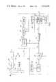
- FIG. 2is an electrical circuit schematic illustrating the low fuel pressure monitor of FIG. 1;
- FIG. 3is an electrical circuit schematic showing a modified circuit embodiment of a portion of the monitor of FIG. 2.
- a power system 11such as in a boat for example, utilizes a two cycle internal combustion engine 12 which selectively receives pressurized fuel from a fuel system 13 to provide output power to operate the power system 11 at a desired speed.
- the engine 12 and the fuel supply 13may consist of any suitable system and the embodiment disclosed in the drawings is for illustrative purposes only.
- a fuel pump 14operates in a conventional manner and receives fuel from a fuel tank 15 through a fuel filter 16.
- a carburetor 17operates in a conventional manner to receive pressurized fuel through a conduit 18 to provide a suitable air-fuel mixture through a conduit 19 to a combustion chamber 20 provided by the two cycle engine 12.
- the engine 12may consist of a conventional two cycle motor frequently found in outboard engines used for boats or the like wherein the air-fuel mixture supplied to chamber 20 is utilized to initially cool an operating piston 21 in chamber 20 so as to establish a safe operating piston temperature before the fuel is ignited to provide a driving output (not shown) to operate a boat propeller or other suitable drive.
- the pressure at a crank case 22 of engine 12may be sensed to provide an input 23 to the fuel pump 14 to provide a timed control for the supply of pressurized fuel from pump 14 to the combustion chamber 20.
- a low fuel pressure monitor 25is connected to the engine 12 and the fuel supply system 13 to sense a drop in the fuel pressure for a predetermined period of time while the engine 12 is operated above a predetermined speed.
- the output of engine 12is connected in a conventional manner to operate an alternator 24 to generate electrical power for the power system 11, such as disclosed in the co-pending U.S. Patent Application Ser. No. 059,054 filed on July 19, 1979 by Richard Elmer Staerzl and entitled Energy Regulating System, U.S. Pat. No. 4,320,335 dated Mar. 16, 1982.
- a pressure switch 26senses the pressure at the connecting conduit 18 through a sensing conduit 27 and provides an electrical output 28 which is connected to a control 29.
- An input 30 of control 29supplies a series of pulses 8 from an output winding (not shown) of the alternator 29 with a frequency proportional to the operating speed of engine 12.
- An alarm 31receives an output 32 from control 29 and provides an intermittent alarm signal when the fuel pressure at conduit 18 decreases below a predetermined magnitude for a predetermined period of time when the engine 12 is operating above a predetermined speed. The alarm 31 also provides a continuous signal if an energizing battery is improperly connected with reverse polarity.
- the series of pulses 8 supplied from the output winding of alternator 24are connected to an input 35 of a NOR gate 36 through serially connected resistors 37 and 38.
- the input 35is also coupled to the system neutral 39 through a noise filtering capacitor 40.
- the series of pulses supplied through circuit 30 by the alternator 24are rectified by a rectifying circuit 41 to provide a substantially constant D.C. voltage level "+V" at a connecting circuit 42.
- an anode circuit of a diode 43is connected to resistor 37 and to the system common 39 through a filtering capacitor 44.
- a cathode circuit of diode 43is connected to the connecting circuit 42 and to the system common 39 through a parallel connected circuit including a Zener diode 45 and a capacitor 46.
- the pressure switch 26is diagramatically illustrated in FIG. 2 as a normally closed switch 47 which opens upon sensing a pressure condition below a predetermined magnitude.
- a base circuit 48 of a PNP type transistor 49is connected to the pressure switch circuit 28 through a connecting resistor 50 and is also connected to the constant potential lead 42 through a resistor 51.
- An emitter circuit 52 of transistor 49is connected to the constant potential lead 42 through a resistor 53 while a collector circuit 54 is connected to the system common 39 through a parallel connected timing circuit 58 including a resistor 55 and a capacitor 56.
- the collector 54is also connected to an input 57 of the NOR gate 36.
- the switch 47When the fuel pressure supplied through conduit 18 by fuel pump 14 is at or above a predetermined magnitude, the switch 47 remains closed to maintain the transistor 49 in a conducting condition.
- the capacitor 56remains fully charged to maintain a high potential disable signal (hereafter referred to as logic "1”) at input 57 to thereby maintain a low voltage signal (hereafter referred to as logic "0") at an output 59 of NOR gate 36.
- switch 47opens to turn off transistor 49. With transistor 49 non-conductive, capacitor 56 discharges through resistor 55 to lower the voltage potential at input 57 of NOR gate 36. After a predetermined time delay, such as five to eight seconds for example, the capacitor 56 discharges to a low voltage level to apply a logic "0" enable signal to input 57 of NOR gate 36.
- engine 12continuously supplies the series of pulses 8 at the output 30 of alternator 24 which have a frequency proportional to the operating speed of engine 12.
- the disable logic "1" signal at input 57will maintain a logic "0" signal at output 59 of NOR gate 36 irrespective of the occurrence of pulses at input 35.
- an enable logic "0" signalappears at input 57 and the NOR gate 36 functions to respond to the alternator generated pulses 8 to provide corresponding pulses 9 at output 59 which are 180° out of phase with the input pulses 8.
- a pulse modifying circuit 60responds to the series of pulses 9 at output 59 to provide a corresponding series of pulses 10 at an output 61 having the same frequency but with a constant uniform pulse width.
- the modifier 60includes an inverting NOR gate 62 having a pair of inputs 63 mutually connected to the output 59 through a timing capacitor 64 and also connected to the system common 39 through a parallel connected circuit 65 including a diode 66 and a resistor 67.
- the capacitor 64 and resistor 67function to provide a delay in the operation of the NOR gate 62 to provide uniform width pulses 10 at output 61.
- An integrator 68includes a parallel connected circuit including a resistor 69 and a capacitor 70 which are connected between the positive voltage lead 42 and an output connecting circuit 71.
- the integrator 68further includes a connecting resistor 72 and a diode 73 which are serially connected between the output 61 of NOR 62 and the output circuit 71.
- the circuitscould be established so that the operation of engine 12 below 1900 RPM will cause the voltage at output circuit 71 to remain at or above a predetermined magnitude, such as 4 volts D.C. for example.
- a predetermined magnitudesuch as 4 volts D.C. for example.
- the voltage at connecting circuit 71will drop below the predetermined level, such as below 4 volts D.C. for example, and will be sufficient to turn on an oscillator 74 to provide reoccurring intermittent output gating pulses at the circuit 32.
- the oscillator 74includes a pair of NOR circuits 75 and 76 interconnected to oscillate under certain controlled conditions.
- the NOR circuit 75has an input 77 connected to the connecting circuit 71 and an input 78 connected to an output 79 of NOR 76.
- An output 80 of NOR 75is connected to both inputs 81 of NOR 76 through a series connecting circuit including a resistor 82 and a capacitor 83 joined at a junction 84.
- a feedback circuit 85includes a resistor 86 connected to the output 79 of NOR circuit 76 and to the junction circuit 84.
- the junction circuit 84is also connected to the connecting circuit 71 of integrator 68 through a noise filtering capacitor 87.
- the oscillator 74With the voltage at input 77 at or above the predetermined magnitude, the oscillator 74 will be in an non-oscillatory state and no gating signals will appear at the output 32. When the voltage at input 77 drops below the predetermined magnitude, the oscillator will oscillate at a frequency determined by the time constant of resistor 86 and capacitor 83 to provide a series of gating pulses through an output resistor 88 to the connecting circuit 32 to cyclically operate the alarm 31.
- the alarm 31includes a buzzer 89, which could also constitute a light or other suitable signaling apparatus, having one lead 90 connected to a positive potential battery terminal 91 and another lead 92 connected to an anode circuit of a silicon control rectifier (SCR) 93.
- a gate circuit 94 of SCR 93is connected to the connecting circuit 32 while a cathode circuit is connected to the system common 39 and to a negative potential battery terminal 95.
- a battery 96is connected to terminals 91 and 95 so that a positive output 97 of battery 96 is connected to terminal 91 while a negative output 98 is connected to the terminal 95.
- the series of cyclic gating pulses supplied through connecting circuit 32 from oscillator 74will cyclically gate the SCR 93 so as to repetitively energize buzzer 89 to provide a cyclical sound occurring at a certain frequency, such as 2 Hz for example.
- a certain frequencysuch as 2 Hz for example.
- Such signal provided by buzzer 89indicates that a sensed low pressure condition has existed for a predetermined period of time at the output of fuel pump 14 and the engine 12 is operating at or above a predetermined speed which might cause an overheated condition at the operating piston 21 and combustion chamber 20.
- FIG. 3illustrates an alternative embodiment of a timing circuit wherein identical components as discussed above will be designated with identical numbers primed.
- the pressure switch 26'includes normally open contacts 100 which close in response to the fuel pressure in conduit 18 dropping below the predetermined magnitude.
- the connecting circuit 28'is connected to the potential source lead 42' through a resistor 101 and is also connected to the gate input 57' through a serially connected resistor 102 and a parallel connected circuit 103 including a diode 104 and a resistor 105.
- a capacitor 106is connected between the gate input 57' and the circuit common 39'. With switch 100 in an open condition in response to normal pressure conditions in conduit 18, the capacitor 106 remains fully charged to maintain a disable signal at the gate input 57'. The closure of switch 100, however, allows the capacitor 106 to discharge through the closed switch 100 to provide an enable signal to the gate input 57'.
- the low fuel pressure monitorprovides a desirable warning in response to the continued existence of a low fuel pressure condition while operating at high engine speeds.
Landscapes
- Engineering & Computer Science (AREA)
- Automation & Control Theory (AREA)
- Mechanical Engineering (AREA)
- Combined Controls Of Internal Combustion Engines (AREA)
- Electrical Control Of Air Or Fuel Supplied To Internal-Combustion Engine (AREA)
Abstract
Description
Claims (3)
Priority Applications (1)
| Application Number | Priority Date | Filing Date | Title |
|---|---|---|---|
| US06/221,625US4413248A (en) | 1980-12-31 | 1980-12-31 | Low fuel pressure monitor for internal combustion engine |
Applications Claiming Priority (1)
| Application Number | Priority Date | Filing Date | Title |
|---|---|---|---|
| US06/221,625US4413248A (en) | 1980-12-31 | 1980-12-31 | Low fuel pressure monitor for internal combustion engine |
Publications (1)
| Publication Number | Publication Date |
|---|---|
| US4413248Atrue US4413248A (en) | 1983-11-01 |
Family
ID=22828600
Family Applications (1)
| Application Number | Title | Priority Date | Filing Date |
|---|---|---|---|
| US06/221,625Expired - LifetimeUS4413248A (en) | 1980-12-31 | 1980-12-31 | Low fuel pressure monitor for internal combustion engine |
Country Status (1)
| Country | Link |
|---|---|
| US (1) | US4413248A (en) |
Cited By (9)
| Publication number | Priority date | Publication date | Assignee | Title |
|---|---|---|---|---|
| US4704598A (en)* | 1985-08-14 | 1987-11-03 | Outboard Marine Corporation | No oil warning circuit |
| AU590673B2 (en)* | 1986-03-07 | 1989-11-09 | Outboard Marine Corporation | No oil warning circuit |
| US4890215A (en)* | 1988-06-30 | 1989-12-26 | Selectrons Ltd. | Electrical apparatus with reverse audible alarm |
| US4945338A (en)* | 1989-01-23 | 1990-07-31 | Outboard Marine Corporation | Alternator powered motor warning system |
| FR2692937A1 (en)* | 1992-06-30 | 1993-12-31 | Renault | Fuel injection system for an internal combustion engine. |
| US5283548A (en)* | 1992-01-13 | 1994-02-01 | Sanshin Kogyo Kabushiki Kaisha | Fuel-flow alarm |
| US5783990A (en)* | 1996-02-28 | 1998-07-21 | Robert Bosch Gmbh | Method of detecting and documenting exhaust-gas relevant malfunctions of a vehicle having an internal combustion engine utilizing onboard means |
| US20070261660A1 (en)* | 2006-05-11 | 2007-11-15 | Richard Wineland | Low fuel pressure warning system |
| US10549833B2 (en) | 2013-02-13 | 2020-02-04 | Ab Volvo Penta | Outboard motor including one or more of cowling, water pump, fuel vaporization suppression, and oil tank features |
Citations (9)
| Publication number | Priority date | Publication date | Assignee | Title |
|---|---|---|---|---|
| US3221317A (en)* | 1962-06-27 | 1965-11-30 | Gen Electric | Audible indicator circuit |
| US3253256A (en)* | 1963-10-10 | 1966-05-24 | Robert E Hull | Emergency fuel system warning device |
| US3371330A (en)* | 1965-01-18 | 1968-02-27 | Handebois Inc | Polarity reversal warning device |
| US3859629A (en)* | 1972-05-15 | 1975-01-07 | Tokyo Shibaura Electric Co | Speed alarm system for an automobile |
| US3893108A (en)* | 1973-12-20 | 1975-07-01 | Texas Instruments Inc | Internal combustion engine protection circuit |
| US4021794A (en)* | 1976-04-14 | 1977-05-03 | Airpax Electronics Incorporated | External condition responsive circuit producing alarm when frequency (engine speed) to amplitude signal (oil pressure) ratio exceeds threshold |
| US4059087A (en)* | 1975-04-04 | 1977-11-22 | Hitachi, Ltd. | Oil pressure detecting apparatus for internal combustion engines |
| US4261209A (en)* | 1978-03-03 | 1981-04-14 | Diesel Kiki Company, Ltd. | Fluid pressure sensing apparatus |
| US4261305A (en)* | 1979-07-26 | 1981-04-14 | Yamaha Hatsudoki Kabushiki Kaisha | Two cycle internal combustion engine |
- 1980
- 1980-12-31USUS06/221,625patent/US4413248A/ennot_activeExpired - Lifetime
Patent Citations (9)
| Publication number | Priority date | Publication date | Assignee | Title |
|---|---|---|---|---|
| US3221317A (en)* | 1962-06-27 | 1965-11-30 | Gen Electric | Audible indicator circuit |
| US3253256A (en)* | 1963-10-10 | 1966-05-24 | Robert E Hull | Emergency fuel system warning device |
| US3371330A (en)* | 1965-01-18 | 1968-02-27 | Handebois Inc | Polarity reversal warning device |
| US3859629A (en)* | 1972-05-15 | 1975-01-07 | Tokyo Shibaura Electric Co | Speed alarm system for an automobile |
| US3893108A (en)* | 1973-12-20 | 1975-07-01 | Texas Instruments Inc | Internal combustion engine protection circuit |
| US4059087A (en)* | 1975-04-04 | 1977-11-22 | Hitachi, Ltd. | Oil pressure detecting apparatus for internal combustion engines |
| US4021794A (en)* | 1976-04-14 | 1977-05-03 | Airpax Electronics Incorporated | External condition responsive circuit producing alarm when frequency (engine speed) to amplitude signal (oil pressure) ratio exceeds threshold |
| US4261209A (en)* | 1978-03-03 | 1981-04-14 | Diesel Kiki Company, Ltd. | Fluid pressure sensing apparatus |
| US4261305A (en)* | 1979-07-26 | 1981-04-14 | Yamaha Hatsudoki Kabushiki Kaisha | Two cycle internal combustion engine |
Cited By (12)
| Publication number | Priority date | Publication date | Assignee | Title |
|---|---|---|---|---|
| US4704598A (en)* | 1985-08-14 | 1987-11-03 | Outboard Marine Corporation | No oil warning circuit |
| AU590673B2 (en)* | 1986-03-07 | 1989-11-09 | Outboard Marine Corporation | No oil warning circuit |
| US4890215A (en)* | 1988-06-30 | 1989-12-26 | Selectrons Ltd. | Electrical apparatus with reverse audible alarm |
| US4945338A (en)* | 1989-01-23 | 1990-07-31 | Outboard Marine Corporation | Alternator powered motor warning system |
| US5283548A (en)* | 1992-01-13 | 1994-02-01 | Sanshin Kogyo Kabushiki Kaisha | Fuel-flow alarm |
| FR2692937A1 (en)* | 1992-06-30 | 1993-12-31 | Renault | Fuel injection system for an internal combustion engine. |
| EP0577477A1 (en)* | 1992-06-30 | 1994-01-05 | Regie Nationale Des Usines Renault S.A. | Fuel injection system for internal combustion engine |
| US5783990A (en)* | 1996-02-28 | 1998-07-21 | Robert Bosch Gmbh | Method of detecting and documenting exhaust-gas relevant malfunctions of a vehicle having an internal combustion engine utilizing onboard means |
| US20070261660A1 (en)* | 2006-05-11 | 2007-11-15 | Richard Wineland | Low fuel pressure warning system |
| US7311076B2 (en)* | 2006-05-11 | 2007-12-25 | Ford Global Technologies, Llc | Low fuel pressure warning system |
| CN101082319B (en)* | 2006-05-11 | 2011-03-30 | 福特环球技术公司 | Low fuel pressure warning system |
| US10549833B2 (en) | 2013-02-13 | 2020-02-04 | Ab Volvo Penta | Outboard motor including one or more of cowling, water pump, fuel vaporization suppression, and oil tank features |
Similar Documents
| Publication | Publication Date | Title |
|---|---|---|
| US4413248A (en) | Low fuel pressure monitor for internal combustion engine | |
| US5291578A (en) | Apparatus for controlling a vehicle fuel pump | |
| KR910015100A (en) | Generator control device and control method and vehicle using the generator control device and control method | |
| JPS57146031A (en) | Method of supplying fuel upon starting in internal combustion engine | |
| EP0781374B1 (en) | Electronic engine load and revolution sensing device | |
| JPH09250416A (en) | Fuel pump driving device of fuel injector internal combustion engine | |
| JPS6390629A (en) | Trouble alarm system for internal combustion engine | |
| JPS6460774A (en) | Ignition timing controller | |
| US4336487A (en) | Generation control apparatus for vehicle generators | |
| KR890013465A (en) | Thermal flow sensor | |
| US3948039A (en) | Hour meter operated responsive to tachometer signal | |
| US4306536A (en) | Pulse controlled spark advance unit for an internal combustion engine ignition system | |
| US4306535A (en) | High speed spark advancer for an internal combustion engine ignition system | |
| US4121547A (en) | Closed loop air-fuel ratio control system for use with internal combustion engine | |
| JPS57143160A (en) | Ignition device for internal combustion engine | |
| US4266181A (en) | Voltage regulator system for vehicle generator | |
| US5044335A (en) | Monitoring arrangement for a fuel filter | |
| US4318387A (en) | External pulse controlled spark advance unit for an internal combustion engine ignition system | |
| US4716355A (en) | Device for controlling a charging generator | |
| US4914419A (en) | Single-wire engine indicator device | |
| US4250444A (en) | Voltage regulator system for vehicle generator | |
| US4395680A (en) | Automobile timing light | |
| GB1588738A (en) | Electrical motor speed regulators | |
| US4704598A (en) | No oil warning circuit | |
| JPS648354A (en) | Electronic ignition controller for internal combustion engine |
Legal Events
| Date | Code | Title | Description |
|---|---|---|---|
| AS | Assignment | Owner name:BRUNSWICK CORPORATION, A CORP. OF WIS., WISCONSIN Free format text:ASSIGNMENT OF ASSIGNORS INTEREST;ASSIGNOR:STAERZL RICHARD E.;REEL/FRAME:003851/0455 Effective date:19801222 | |
| STCF | Information on status: patent grant | Free format text:PATENTED CASE | |
| AS | Assignment | Owner name:BRUNSWICK CORPORATION, ONE BRUNSWICK PLAZA, SKOKIE Free format text:TO CORRECT THE HABITAT OF THE ASSIGNEE RECORDED DEC 31, 1980, ASSIGNOR DOES HEREBY ASSIGNS THE ENTIRE INTEREST. ON REEL 3851, FRAMES 455-457;ASSIGNOR:STAERZL, RICHARD E.;REEL/FRAME:004183/0130 Effective date:19831013 | |
| FEPP | Fee payment procedure | Free format text:PAYOR NUMBER ASSIGNED (ORIGINAL EVENT CODE: ASPN); ENTITY STATUS OF PATENT OWNER: LARGE ENTITY | |
| MAFP | Maintenance fee payment | Free format text:PAYMENT OF MAINTENANCE FEE, 4TH YEAR, PL 96-517 (ORIGINAL EVENT CODE: M170); ENTITY STATUS OF PATENT OWNER: LARGE ENTITY Year of fee payment:4 | |
| FEPP | Fee payment procedure | Free format text:PAYOR NUMBER ASSIGNED (ORIGINAL EVENT CODE: ASPN); ENTITY STATUS OF PATENT OWNER: LARGE ENTITY Free format text:PAYER NUMBER DE-ASSIGNED (ORIGINAL EVENT CODE: RMPN); ENTITY STATUS OF PATENT OWNER: LARGE ENTITY | |
| MAFP | Maintenance fee payment | Free format text:PAYMENT OF MAINTENANCE FEE, 8TH YEAR, PL 96-517 (ORIGINAL EVENT CODE: M171); ENTITY STATUS OF PATENT OWNER: LARGE ENTITY Year of fee payment:8 | |
| FEPP | Fee payment procedure | Free format text:MAINTENANCE FEE HAS ALREADY BEEN PAID. REFUND IS SCHEDULED (ORIGINAL EVENT CODE: F160); ENTITY STATUS OF PATENT OWNER: LARGE ENTITY | |
| MAFP | Maintenance fee payment | Free format text:PAYMENT OF MAINTENANCE FEE, 12TH YEAR, LARGE ENTITY (ORIGINAL EVENT CODE: M185); ENTITY STATUS OF PATENT OWNER: LARGE ENTITY Year of fee payment:12 |