US4412975A - Fired process heater - Google Patents
Fired process heaterDownload PDFInfo
- Publication number
- US4412975A US4412975AUS06/331,485US33148581AUS4412975AUS 4412975 AUS4412975 AUS 4412975AUS 33148581 AUS33148581 AUS 33148581AUS 4412975 AUS4412975 AUS 4412975A
- Authority
- US
- United States
- Prior art keywords
- side walls
- contiguous
- walls
- floor
- combustion gas
- Prior art date
- Legal status (The legal status is an assumption and is not a legal conclusion. Google has not performed a legal analysis and makes no representation as to the accuracy of the status listed.)
- Expired - Lifetime
Links
- 238000000034methodMethods0.000titleabstractdescription27
- 239000000567combustion gasSubstances0.000claimsabstractdescription41
- 239000012530fluidSubstances0.000claimsdescription21
- 229930195733hydrocarbonNatural products0.000claimsdescription11
- 150000002430hydrocarbonsChemical class0.000claimsdescription11
- 210000001364upper extremityAnatomy0.000claimsdescription6
- 238000002352steam pyrolysisMethods0.000claimsdescription4
- 229910052739hydrogenInorganic materials0.000claimsdescription2
- 239000007789gasSubstances0.000abstractdescription15
- 230000004907fluxEffects0.000description12
- 239000003054catalystSubstances0.000description7
- 239000004215Carbon black (E152)Substances0.000description5
- 238000005336crackingMethods0.000description5
- 238000010438heat treatmentMethods0.000description5
- 210000003141lower extremityAnatomy0.000description5
- 238000004230steam crackingMethods0.000description5
- 238000006243chemical reactionMethods0.000description3
- 239000000571cokeSubstances0.000description3
- 239000000446fuelSubstances0.000description3
- 238000000629steam reformingMethods0.000description3
- ATUOYWHBWRKTHZ-UHFFFAOYSA-NPropaneChemical compoundCCCATUOYWHBWRKTHZ-UHFFFAOYSA-N0.000description2
- 238000010521absorption reactionMethods0.000description2
- 238000013459approachMethods0.000description2
- 238000004891communicationMethods0.000description2
- 230000007423decreaseEffects0.000description2
- 238000013461designMethods0.000description2
- VNWKTOKETHGBQD-UHFFFAOYSA-NmethaneChemical compoundCVNWKTOKETHGBQD-UHFFFAOYSA-N0.000description2
- 239000003921oilSubstances0.000description2
- 238000013021overheatingMethods0.000description2
- 238000010791quenchingMethods0.000description2
- UGFAIRIUMAVXCW-UHFFFAOYSA-NCarbon monoxideChemical compound[O+]#[C-]UGFAIRIUMAVXCW-UHFFFAOYSA-N0.000description1
- OTMSDBZUPAUEDD-UHFFFAOYSA-NEthaneChemical compoundCCOTMSDBZUPAUEDD-UHFFFAOYSA-N0.000description1
- VGGSQFUCUMXWEO-UHFFFAOYSA-NEtheneChemical compoundC=CVGGSQFUCUMXWEO-UHFFFAOYSA-N0.000description1
- 239000005977EthyleneSubstances0.000description1
- UFHFLCQGNIYNRP-UHFFFAOYSA-NHydrogenChemical compound[H][H]UFHFLCQGNIYNRP-UHFFFAOYSA-N0.000description1
- 150000001336alkenesChemical class0.000description1
- WYTGDNHDOZPMIW-RCBQFDQVSA-NalstonineNatural productsC1=CC2=C3C=CC=CC3=NC2=C2N1C[C@H]1[C@H](C)OC=C(C(=O)OC)[C@H]1C2WYTGDNHDOZPMIW-RCBQFDQVSA-N0.000description1
- 230000015572biosynthetic processEffects0.000description1
- 238000001193catalytic steam reformingMethods0.000description1
- 238000001311chemical methods and processMethods0.000description1
- 238000002485combustion reactionMethods0.000description1
- 238000001816coolingMethods0.000description1
- 238000004821distillationMethods0.000description1
- 239000003546flue gasSubstances0.000description1
- 239000001257hydrogenSubstances0.000description1
- 238000004519manufacturing processMethods0.000description1
- 239000000203mixtureSubstances0.000description1
- 239000002245particleSubstances0.000description1
- 235000020030perryNutrition0.000description1
- 239000003208petroleumSubstances0.000description1
- 239000001294propaneSubstances0.000description1
- 230000005855radiationEffects0.000description1
- 239000000126substanceSubstances0.000description1
- 238000003786synthesis reactionMethods0.000description1
- 238000004227thermal crackingMethods0.000description1
- 238000012546transferMethods0.000description1
Images


Classifications
- C—CHEMISTRY; METALLURGY
- C01—INORGANIC CHEMISTRY
- C01B—NON-METALLIC ELEMENTS; COMPOUNDS THEREOF; METALLOIDS OR COMPOUNDS THEREOF NOT COVERED BY SUBCLASS C01C
- C01B3/00—Hydrogen; Gaseous mixtures containing hydrogen; Separation of hydrogen from mixtures containing it; Purification of hydrogen
- C01B3/02—Production of hydrogen or of gaseous mixtures containing a substantial proportion of hydrogen
- C01B3/32—Production of hydrogen or of gaseous mixtures containing a substantial proportion of hydrogen by reaction of gaseous or liquid organic compounds with gasifying agents, e.g. water, carbon dioxide, air
- C01B3/34—Production of hydrogen or of gaseous mixtures containing a substantial proportion of hydrogen by reaction of gaseous or liquid organic compounds with gasifying agents, e.g. water, carbon dioxide, air by reaction of hydrocarbons with gasifying agents
- C01B3/38—Production of hydrogen or of gaseous mixtures containing a substantial proportion of hydrogen by reaction of gaseous or liquid organic compounds with gasifying agents, e.g. water, carbon dioxide, air by reaction of hydrocarbons with gasifying agents using catalysts
- C01B3/384—Production of hydrogen or of gaseous mixtures containing a substantial proportion of hydrogen by reaction of gaseous or liquid organic compounds with gasifying agents, e.g. water, carbon dioxide, air by reaction of hydrocarbons with gasifying agents using catalysts the catalyst being continuously externally heated
- B—PERFORMING OPERATIONS; TRANSPORTING
- B01—PHYSICAL OR CHEMICAL PROCESSES OR APPARATUS IN GENERAL
- B01J—CHEMICAL OR PHYSICAL PROCESSES, e.g. CATALYSIS OR COLLOID CHEMISTRY; THEIR RELEVANT APPARATUS
- B01J8/00—Chemical or physical processes in general, conducted in the presence of fluids and solid particles; Apparatus for such processes
- B01J8/02—Chemical or physical processes in general, conducted in the presence of fluids and solid particles; Apparatus for such processes with stationary particles, e.g. in fixed beds
- B01J8/06—Chemical or physical processes in general, conducted in the presence of fluids and solid particles; Apparatus for such processes with stationary particles, e.g. in fixed beds in tube reactors; the solid particles being arranged in tubes
- B01J8/062—Chemical or physical processes in general, conducted in the presence of fluids and solid particles; Apparatus for such processes with stationary particles, e.g. in fixed beds in tube reactors; the solid particles being arranged in tubes being installed in a furnace
- C—CHEMISTRY; METALLURGY
- C01—INORGANIC CHEMISTRY
- C01B—NON-METALLIC ELEMENTS; COMPOUNDS THEREOF; METALLOIDS OR COMPOUNDS THEREOF NOT COVERED BY SUBCLASS C01C
- C01B2203/00—Integrated processes for the production of hydrogen or synthesis gas
- C01B2203/02—Processes for making hydrogen or synthesis gas
- C01B2203/0205—Processes for making hydrogen or synthesis gas containing a reforming step
- C01B2203/0227—Processes for making hydrogen or synthesis gas containing a reforming step containing a catalytic reforming step
- C01B2203/0233—Processes for making hydrogen or synthesis gas containing a reforming step containing a catalytic reforming step the reforming step being a steam reforming step
- C—CHEMISTRY; METALLURGY
- C01—INORGANIC CHEMISTRY
- C01B—NON-METALLIC ELEMENTS; COMPOUNDS THEREOF; METALLOIDS OR COMPOUNDS THEREOF NOT COVERED BY SUBCLASS C01C
- C01B2203/00—Integrated processes for the production of hydrogen or synthesis gas
- C01B2203/06—Integration with other chemical processes
- C01B2203/062—Hydrocarbon production, e.g. Fischer-Tropsch process
- C—CHEMISTRY; METALLURGY
- C01—INORGANIC CHEMISTRY
- C01B—NON-METALLIC ELEMENTS; COMPOUNDS THEREOF; METALLOIDS OR COMPOUNDS THEREOF NOT COVERED BY SUBCLASS C01C
- C01B2203/00—Integrated processes for the production of hydrogen or synthesis gas
- C01B2203/08—Methods of heating or cooling
- C01B2203/0805—Methods of heating the process for making hydrogen or synthesis gas
- C01B2203/0811—Methods of heating the process for making hydrogen or synthesis gas by combustion of fuel
- C01B2203/0816—Heating by flames
- C—CHEMISTRY; METALLURGY
- C01—INORGANIC CHEMISTRY
- C01B—NON-METALLIC ELEMENTS; COMPOUNDS THEREOF; METALLOIDS OR COMPOUNDS THEREOF NOT COVERED BY SUBCLASS C01C
- C01B2203/00—Integrated processes for the production of hydrogen or synthesis gas
- C01B2203/08—Methods of heating or cooling
- C01B2203/0805—Methods of heating the process for making hydrogen or synthesis gas
- C01B2203/0838—Methods of heating the process for making hydrogen or synthesis gas by heat exchange with exothermic reactions, other than by combustion of fuel
- C01B2203/0844—Methods of heating the process for making hydrogen or synthesis gas by heat exchange with exothermic reactions, other than by combustion of fuel the non-combustive exothermic reaction being another reforming reaction as defined in groups C01B2203/02 - C01B2203/0294
- C—CHEMISTRY; METALLURGY
- C01—INORGANIC CHEMISTRY
- C01B—NON-METALLIC ELEMENTS; COMPOUNDS THEREOF; METALLOIDS OR COMPOUNDS THEREOF NOT COVERED BY SUBCLASS C01C
- C01B2203/00—Integrated processes for the production of hydrogen or synthesis gas
- C01B2203/08—Methods of heating or cooling
- C01B2203/0805—Methods of heating the process for making hydrogen or synthesis gas
- C01B2203/0866—Methods of heating the process for making hydrogen or synthesis gas by combination of different heating methods
- C—CHEMISTRY; METALLURGY
- C01—INORGANIC CHEMISTRY
- C01B—NON-METALLIC ELEMENTS; COMPOUNDS THEREOF; METALLOIDS OR COMPOUNDS THEREOF NOT COVERED BY SUBCLASS C01C
- C01B2203/00—Integrated processes for the production of hydrogen or synthesis gas
- C01B2203/12—Feeding the process for making hydrogen or synthesis gas
- C01B2203/1205—Composition of the feed
- C01B2203/1211—Organic compounds or organic mixtures used in the process for making hydrogen or synthesis gas
- C01B2203/1235—Hydrocarbons
- C01B2203/1241—Natural gas or methane
- C—CHEMISTRY; METALLURGY
- C01—INORGANIC CHEMISTRY
- C01B—NON-METALLIC ELEMENTS; COMPOUNDS THEREOF; METALLOIDS OR COMPOUNDS THEREOF NOT COVERED BY SUBCLASS C01C
- C01B2203/00—Integrated processes for the production of hydrogen or synthesis gas
- C01B2203/12—Feeding the process for making hydrogen or synthesis gas
- C01B2203/1205—Composition of the feed
- C01B2203/1211—Organic compounds or organic mixtures used in the process for making hydrogen or synthesis gas
- C01B2203/1235—Hydrocarbons
- C01B2203/1247—Higher hydrocarbons
- C—CHEMISTRY; METALLURGY
- C10—PETROLEUM, GAS OR COKE INDUSTRIES; TECHNICAL GASES CONTAINING CARBON MONOXIDE; FUELS; LUBRICANTS; PEAT
- C10G—CRACKING HYDROCARBON OILS; PRODUCTION OF LIQUID HYDROCARBON MIXTURES, e.g. BY DESTRUCTIVE HYDROGENATION, OLIGOMERISATION, POLYMERISATION; RECOVERY OF HYDROCARBON OILS FROM OIL-SHALE, OIL-SAND, OR GASES; REFINING MIXTURES MAINLY CONSISTING OF HYDROCARBONS; REFORMING OF NAPHTHA; MINERAL WAXES
- C10G2400/00—Products obtained by processes covered by groups C10G9/00 - C10G69/14
- C10G2400/20—C2-C4 olefins
- C—CHEMISTRY; METALLURGY
- C10—PETROLEUM, GAS OR COKE INDUSTRIES; TECHNICAL GASES CONTAINING CARBON MONOXIDE; FUELS; LUBRICANTS; PEAT
- C10G—CRACKING HYDROCARBON OILS; PRODUCTION OF LIQUID HYDROCARBON MIXTURES, e.g. BY DESTRUCTIVE HYDROGENATION, OLIGOMERISATION, POLYMERISATION; RECOVERY OF HYDROCARBON OILS FROM OIL-SHALE, OIL-SAND, OR GASES; REFINING MIXTURES MAINLY CONSISTING OF HYDROCARBONS; REFORMING OF NAPHTHA; MINERAL WAXES
- C10G2400/00—Products obtained by processes covered by groups C10G9/00 - C10G69/14
- C10G2400/26—Fuel gas
Definitions
- This inventionrelates to fired, tubular furnaces for heating hydrocarbons. More specifically, the invention relates to a process and apparatus for heating hydrocarbons in furnaces employing vertical tubes wherein combustion gas is passed upwardly through the radiant chamber of the heater or furnace.
- Vertical tube, fired heatersare well known in the petroleum and chemical process industries and are utilized to heat hydrocarbon feed streams in a variety of processes such as distillation, thermal cracking, visbreaking, and, of particular interest here, steam cracking and steam reforming.
- Heater designis governed by the objectives of the particular process as well as the general objective of high furnace efficiency, that is, the amount of heat absorbed by the process fluid divided by the heating value of fuel input to furnace.
- process furnace designsee Perry and Chilton, "Chemical Engineers Handbook", Fifth Edition, McGraw-Hill Book Company, pp. 9-34 to 9-38.
- a very high, uniform heat flux from combustion gas to process fluidis utilized to bring the fluid quickly to a cracking temperature in the range of from about 815° C. to about 925° C.
- the high, uniform heat flux requirementis normally achieved through use of back-mixed combustion gas conditions throughout the radiant chamber, that is, approximating a well-stirred reactor.
- the back-mixed combustion gas conditionis brought about by turbulent heat input from a plurality of burners mounted in the radiant chamber enclosure.
- a conventional arrangement for achieving thisis through use of sidewall burners in optional combination with floor burners in a box type radiant chamber wherein combustion gas passes upwardly through the radiant chamber to a convection section.
- a process and apparatusare provided for heating hydrocarbons by indirect heat exchange with combustion gas in the radiant chamber of a fired tubular heater having a plurality of straight, vertical, tubular heat exchange means in single pass heat exchange relationship with the combustion gas wherein the combustion gas passing over the lower portions of the tubular heat exchange means is predominantly in a back-mixed, ie.--well-stirred, flow condition and the combustion gas passing over the upper portions thereof is predominantly in a plug-flow condition, ie.--substantially each gas particle having approximately the same residence time.
- FIG. 1is a cross-sectional view of a commercial prior art process heater employing a vertical serpentine coil and shows the back-mixed combustion gas flow conditions throughout the radiant chamber which result from the burner placement and geometry of the chamber.
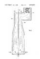
- FIG. 2is a cross-sectional view of a process heater of the invention which employs single pass vertical tubes in combination with burner placement and radiant chamber geometry that result in back-mixed gas flow conditions in the lower portion of the radiant chamber and plug-flow conditions in the upper portion thereof.
- FIG. 2Ais a side view of FIG. 2 and illustrates single pass, vertical tubes.
- FIG. 3is the same as FIG. 2 except that the upper portion of the radiant chamber has two, parallel, opposed, upper side walls.
- FIG. 4is a cross-sectional view of another process heater of the invention which employs bayonet type tubular heat exchange means, ie.--two concentric tubes, having only a single pass in heat exchange relationship with the combustion gas but two passes on the process fluid side.
- the burner placement and radiant chamber configurationresult in predominantly back-mixed gas flow conditions in the lower portion of the radiant chamber and predominantly plug-flow conditions in the upper portion thereof.
- Radiant chamber 201is formed by horizontal floor 202, opposed vertical end walls 203 (see FIG. 2A) contiguous with the floor, opposed vertical lower side walls 204 that are contiguous with the floor 202 and end walls 203, opposed intermediate side walls 205 contiguous with end walls 203 and lower side walls 204 and which slope inwardly at an angle from about 10 to about 30 degrees, preferably from about 10 to about 20 degrees, from a plane projected by upward extension of the lower side walls.
- the upper portion of radiant chamber 201has combustion gas outlet means 206 which is contiguous with end walls 203 and intermediate side walls 205.
- the combustion gas outlet means 206is formed by an extension of end walls 203, a single upper side wall 207, and roof 209.
- the combustion gas outlet means 206is a passageway constructed in form suitable for directing combustion gas across convection coils 210 located in convection chamber 211 where relatively low level heat is recovered from the flue gas.
- this passagewayis an opening of rectangular cross-section.
- the radiant chamber 201encloses a plurality of straight, vertical, tubular heat exchange means 212 which are disposed centrally within radiant chamber 201 parallel to the lower side walls 204, extending through floor 202 and roof 209, and terminating at their upper extremity proximate combustion gas outlet means 206.
- the tubular heat exchange devicesare single tubes having a single pass on the process fluid side as well as on the combustion gas side. In steam pyrolysis applications, these tubes are preferably from about 1.8 to about 5.1 cm inside diameter which is suitable for high severity cracking in very short residence times.
- hydrocarbon feedstockis introduced to lower extremities of the tubes proximate floor 202 via tube inlets 213 which, in turn, are fed from inlet manifold 214 via inlet pigtails (not shown).
- tube inlets 213 and inlet manifold 214may be located within radiant chamber 201.
- Process fluidis heated in its upward passage through the tubes and discharged at their upper extremities via tube outlets 215 proximate combustion gas outlet means 206.
- heated process fluidis collected in an outlet manifold similar to inlet manifold 214.
- tube outlets 215are closely coupled to cracked gas quench devices which may utilize direct or indirect cooling.
- tubes 212may be branched within radiant chamber 201.
- two tubesmay be joined at one third the height of the radiant chamber and then joined with another pair of tubes at two thirds the height of the radiant chamber with the result of one tube outlet for every four tube inlets.
- the heateris so configured that hot combustion gas proximate to and passing over the lower portions of tubular heat exchange means 212 is in a predominantly back-mixed flow condition 217 and is at a substantially uniform temperature.
- intermediate side walls 205channel the gas into predominantly plug-flow condition 218 proximate the upper portions of tubular heat exchange means 212 as it passes over them and the combustion gas decreases in temperature as it passes upwardly.
- the physical proportions of the radiant chamberare selected such that:
- Lis the length of the lower side walls between the end walls (see FIG. 2A)
- His the height of lower sidewalls
- Wis the width of the radiant chamber between the lower side walls.
- a fuel/air mixtureis introduced to a plurality of burners 216 proximate floor 202 in the lower portion of the radiant chamber which are disposed to direct combustion gas therefrom upwardly into the chamber in indirect heat exchange relationship with tubular heat exchange means 212 and the process fluid therein.
- no burnersare mounted in the end walls 203, lower side walls 204, intermediate side walls 205, and combustion gas outlet means 206 since a large amount of combustion gas introduced to the radiant chamber at locations other than proximate the floor will tend to extend the region of back-mixed gas flow upwardly into the region of desired plug-flow conditions.
- small wall burnersmay be utilized in the upper portion of the radiant chamber provided that their combustion gas discharge does not appreciably disrupt plug-flow of combustion gas in the upper portion.
- the ratio of heat fluxes between the lower and upper extremities of the cracking tubes proximate respectively roof 209 and floor 202is from about 3 to about 7.
- the introduction of heat proximate the tube inlets at their lower extremities under back-mixed combustion gas flow conditions, in combination with heat absorption proximate the tube outlets at their upper extremities under predominantly plug-flow combustion gas conditionspermits control of temperature profile over the tube length while maintaining high thermal efficiency of the furnace.
- FIG. 3is the same as FIG. 2 except that combustion gas outlet means 306 is comprised of upper side wall 308 in addition to end wall extensions 303 (not shown), roof 309, and upper side wall 307 which is opposed and parallel to upper side wall 308.
- This configurationeffectively extends the region of combustion gas plug-flow and also results in higher ratio of convective to radiant heat transfer in the upper portion of the radiant chamber.
- reference numbers 401 through 411 and 416 through 418correspond respectively to FIG. 2 reference numbers 201 through 211 and 216 through 218.
- FIG. 4illustrates an embodiment of the invention having bayonet type tubular heat exchange means 420 which are useful for, among other things, catalytic steam reforming of hydrocarbons ranging from methane through heavy gas oil to produce hydrogen-containing gas, for example, synthesis gas.
- catalytic steam reforming of hydrocarbonsranging from methane through heavy gas oil to produce hydrogen-containing gas, for example, synthesis gas.
- control of temperature profile over the process fluid route within reformer tubesis quite critical.
- the present inventionis well suited to meet this requirement.
- Tubular heat exchange devices 420are comprised of outer tube 421 and one or more inner tubes 422 to form a space for containment of catalyst 423 which is loaded through closure 426. Suitable means (not shown) are employed at the bottom of the catalyst space for catalyst removal.
- Outer tube 421is fitted with a hydrocarbon feed inlet 424 at the lower extremity thereof and inner tube(s) 422 are in fluid communication with product gas outlet 425 at their lower extremities.
- Upper extremities of inner tubes 422are in fluid communication with the catalyst space so that process fluid process upwardly through the catalyst bed in single pass heat exchange relationship with combustion gas in radiant chamber 401 and then downwardly within inner tubes 422 in heat exchange relationship with the upwardly flowing fluid in the catalyst space.
- the bayonet exchange devices 420extend through radiant chamber 401 and extend downwardly outside the radiant chamber where, in the absence of hot combustion gas, they function as feed/effluent heat exchangers.
Landscapes
- Chemical & Material Sciences (AREA)
- Chemical Kinetics & Catalysis (AREA)
- Organic Chemistry (AREA)
- Health & Medical Sciences (AREA)
- General Health & Medical Sciences (AREA)
- Engineering & Computer Science (AREA)
- Combustion & Propulsion (AREA)
- Inorganic Chemistry (AREA)
- Production Of Liquid Hydrocarbon Mixture For Refining Petroleum (AREA)
Abstract
Description
H/2(1/W+1/L)≦2.5
Claims (4)
H/2(1/W+1/L)≦2.5.
Priority Applications (1)
| Application Number | Priority Date | Filing Date | Title |
|---|---|---|---|
| US06/331,485US4412975A (en) | 1980-07-08 | 1981-12-17 | Fired process heater |
Applications Claiming Priority (2)
| Application Number | Priority Date | Filing Date | Title |
|---|---|---|---|
| US06/166,880US4324649A (en) | 1980-07-08 | 1980-07-08 | Fired process heater |
| US06/331,485US4412975A (en) | 1980-07-08 | 1981-12-17 | Fired process heater |
Related Parent Applications (1)
| Application Number | Title | Priority Date | Filing Date |
|---|---|---|---|
| US06/166,880DivisionUS4324649A (en) | 1980-07-08 | 1980-07-08 | Fired process heater |
Publications (1)
| Publication Number | Publication Date |
|---|---|
| US4412975Atrue US4412975A (en) | 1983-11-01 |
Family
ID=26862643
Family Applications (1)
| Application Number | Title | Priority Date | Filing Date |
|---|---|---|---|
| US06/331,485Expired - LifetimeUS4412975A (en) | 1980-07-08 | 1981-12-17 | Fired process heater |
Country Status (1)
| Country | Link |
|---|---|
| US (1) | US4412975A (en) |
Cited By (12)
| Publication number | Priority date | Publication date | Assignee | Title |
|---|---|---|---|---|
| EP0253633A3 (en)* | 1986-07-15 | 1989-02-08 | The Dow Chemical Company | Heat exchanger, method of making heat exchanger, and hydrocarbon cracking furnace containing heat exchanger |
| US4838897A (en)* | 1985-04-10 | 1989-06-13 | Hitachi, Ltd. | Reformer |
| US5078857A (en)* | 1988-09-13 | 1992-01-07 | Melton M Shannon | Delayed coking and heater therefor |
| US5181990A (en)* | 1986-01-16 | 1993-01-26 | Babcock-Hitachi Kabushiki Kaisha | Pyrolysis furnace for olefin production |
| US6425757B1 (en)* | 2001-06-13 | 2002-07-30 | Abb Lummus Global Inc. | Pyrolysis heater with paired burner zoned firing system |
| US20040147794A1 (en)* | 2003-01-24 | 2004-07-29 | Brown David J. | Process for cracking hydrocarbons using improved furnace reactor tubes |
| US20040259045A1 (en)* | 2003-06-19 | 2004-12-23 | Leger Christopher Brian | Oxy-fuel fired process heaters |
| US20050106518A1 (en)* | 2003-11-19 | 2005-05-19 | Platvoet Erwin M. | Pyrolysis heater |
| US20050223644A1 (en)* | 2004-04-09 | 2005-10-13 | Kim Hyun Y | High temperature reformer |
| US20080098967A1 (en)* | 2006-11-01 | 2008-05-01 | Ashutosh Garg | Fired heater |
| US8128399B1 (en)* | 2008-02-22 | 2012-03-06 | Great Southern Flameless, Llc | Method and apparatus for controlling gas flow patterns inside a heater chamber and equalizing radiant heat flux to a double fired coil |
| US20160076761A1 (en)* | 2014-09-17 | 2016-03-17 | Atd Combustors, Llc | Furnaces and methods of reducing heat degrading of metal heating coils of furnaces |
Citations (9)
| Publication number | Priority date | Publication date | Assignee | Title |
|---|---|---|---|---|
| US2342011A (en)* | 1941-04-10 | 1944-02-15 | Kellogg M W Co | Furnace for heating fluids |
| US2625916A (en)* | 1950-11-16 | 1953-01-20 | Universal Oil Prod Co | Modified up-draft type of heaters |
| US2625918A (en)* | 1949-01-19 | 1953-01-20 | Thomas M Lumly | Fluid heating apparatus |
| US2721735A (en)* | 1951-10-23 | 1955-10-25 | Shell Dev | Tubular heater with partial flue gas recirculation and heating method |
| US2825313A (en)* | 1955-01-10 | 1958-03-04 | Born Engineering Company | Heaters |
| US3066656A (en)* | 1960-05-03 | 1962-12-04 | Universal Oil Prod Co | Fluid heater |
| US3182638A (en)* | 1963-02-19 | 1965-05-11 | Foster Wheeler Corp | Fired heater |
| US3385269A (en)* | 1967-01-26 | 1968-05-28 | Selas Corp Of America | Tube heating furnace |
| US3671198A (en)* | 1970-06-15 | 1972-06-20 | Pullman Inc | Cracking furnace having thin straight single pass reaction tubes |
- 1981
- 1981-12-17USUS06/331,485patent/US4412975A/ennot_activeExpired - Lifetime
Patent Citations (9)
| Publication number | Priority date | Publication date | Assignee | Title |
|---|---|---|---|---|
| US2342011A (en)* | 1941-04-10 | 1944-02-15 | Kellogg M W Co | Furnace for heating fluids |
| US2625918A (en)* | 1949-01-19 | 1953-01-20 | Thomas M Lumly | Fluid heating apparatus |
| US2625916A (en)* | 1950-11-16 | 1953-01-20 | Universal Oil Prod Co | Modified up-draft type of heaters |
| US2721735A (en)* | 1951-10-23 | 1955-10-25 | Shell Dev | Tubular heater with partial flue gas recirculation and heating method |
| US2825313A (en)* | 1955-01-10 | 1958-03-04 | Born Engineering Company | Heaters |
| US3066656A (en)* | 1960-05-03 | 1962-12-04 | Universal Oil Prod Co | Fluid heater |
| US3182638A (en)* | 1963-02-19 | 1965-05-11 | Foster Wheeler Corp | Fired heater |
| US3385269A (en)* | 1967-01-26 | 1968-05-28 | Selas Corp Of America | Tube heating furnace |
| US3671198A (en)* | 1970-06-15 | 1972-06-20 | Pullman Inc | Cracking furnace having thin straight single pass reaction tubes |
Non-Patent Citations (3)
| Title |
|---|
| Hottel et al.; "The Effect of Gas Flow Patterns on Radiative Transfer in Cylindrical Furnaces"; Heat Mass Transfer, vol. 8, pp. 1153-1169. |
| Mekler, L. A.; "Process Design of Tubular Heaters", Transactions of ASME, Jul., 1956, pp. 1103-1111. |
| Perry et al.; Chemical Engineers' Handbook, 5th Ed.; McGraw-Hill, N.Y.; pp. 9-34 to 9-38. |
Cited By (20)
| Publication number | Priority date | Publication date | Assignee | Title |
|---|---|---|---|---|
| US4838897A (en)* | 1985-04-10 | 1989-06-13 | Hitachi, Ltd. | Reformer |
| US5181990A (en)* | 1986-01-16 | 1993-01-26 | Babcock-Hitachi Kabushiki Kaisha | Pyrolysis furnace for olefin production |
| EP0253633A3 (en)* | 1986-07-15 | 1989-02-08 | The Dow Chemical Company | Heat exchanger, method of making heat exchanger, and hydrocarbon cracking furnace containing heat exchanger |
| US5078857A (en)* | 1988-09-13 | 1992-01-07 | Melton M Shannon | Delayed coking and heater therefor |
| US6425757B1 (en)* | 2001-06-13 | 2002-07-30 | Abb Lummus Global Inc. | Pyrolysis heater with paired burner zoned firing system |
| WO2002100982A1 (en)* | 2001-06-13 | 2002-12-19 | Abb Lummus Global Inc. | Pyrolysis heater with paired burner zoned firing system |
| SG152064A1 (en)* | 2003-01-24 | 2009-05-29 | Stone & Webster Process Tech | A process for cracking hydrocarbons using improved furnace reactor tubes |
| US7482502B2 (en) | 2003-01-24 | 2009-01-27 | Stone & Webster Process Technology, Inc. | Process for cracking hydrocarbons using improved furnace reactor tubes |
| US20040147794A1 (en)* | 2003-01-24 | 2004-07-29 | Brown David J. | Process for cracking hydrocarbons using improved furnace reactor tubes |
| US6910878B2 (en) | 2003-06-19 | 2005-06-28 | Praxair Technology, Inc. | Oxy-fuel fired process heaters |
| US20040259045A1 (en)* | 2003-06-19 | 2004-12-23 | Leger Christopher Brian | Oxy-fuel fired process heaters |
| US20050106518A1 (en)* | 2003-11-19 | 2005-05-19 | Platvoet Erwin M. | Pyrolysis heater |
| US7172412B2 (en)* | 2003-11-19 | 2007-02-06 | Abb Lummus Global Inc. | Pyrolysis heater |
| US20050223644A1 (en)* | 2004-04-09 | 2005-10-13 | Kim Hyun Y | High temperature reformer |
| US7556659B2 (en)* | 2004-04-09 | 2009-07-07 | Hyun Yong Kim | High temperature reformer |
| US7484478B2 (en)* | 2006-11-01 | 2009-02-03 | Ashutosh Garg | Fired heater |
| US20080098967A1 (en)* | 2006-11-01 | 2008-05-01 | Ashutosh Garg | Fired heater |
| US8128399B1 (en)* | 2008-02-22 | 2012-03-06 | Great Southern Flameless, Llc | Method and apparatus for controlling gas flow patterns inside a heater chamber and equalizing radiant heat flux to a double fired coil |
| US20160076761A1 (en)* | 2014-09-17 | 2016-03-17 | Atd Combustors, Llc | Furnaces and methods of reducing heat degrading of metal heating coils of furnaces |
| US9989246B2 (en)* | 2014-09-17 | 2018-06-05 | Atd Combustors, Llc | Furnaces and methods of reducing heat degrading of metal heating coils of furnaces |
Similar Documents
| Publication | Publication Date | Title |
|---|---|---|
| US4324649A (en) | Fired process heater | |
| US4499055A (en) | Furnace having bent/single-pass tubes | |
| US3407789A (en) | Heating apparatus and process | |
| JP4871928B2 (en) | Cracking furnace with more uniform heating | |
| US4412975A (en) | Fired process heater | |
| US20080142411A1 (en) | Cracking Furnace | |
| US4999089A (en) | Cracking furnace | |
| KR900005091B1 (en) | Pyrolysis heater | |
| US3820955A (en) | Horizontal high severity furnace | |
| US5427655A (en) | High capacity rapid quench boiler | |
| CZ117696A3 (en) | Catalytic reaction vessel for endothermic reactions | |
| US20020110505A1 (en) | Reformer process with variable heat flux side-fired burner system | |
| US3403722A (en) | Cooling apparatus and process | |
| JP5619174B2 (en) | HEAT EXCHANGE DEVICE AND ITS MANUFACTURING METHOD | |
| US6395251B1 (en) | Steam-hydrocarbon reformer and process | |
| US20160334135A1 (en) | Double fired u-tube fired heater | |
| KR20200029091A (en) | Heater for a hydrocarbon stream | |
| US11105500B2 (en) | Film temperature optimizer for fired process heaters | |
| KR102220200B1 (en) | Fired heater | |
| CS266821B1 (en) | Furnace for thermal breakdown of hydrocarbons |
Legal Events
| Date | Code | Title | Description |
|---|---|---|---|
| STCF | Information on status: patent grant | Free format text:PATENTED CASE | |
| MAFP | Maintenance fee payment | Free format text:PAYMENT OF MAINTENANCE FEE, 4TH YEAR, PL 96-517 (ORIGINAL EVENT CODE: M170); ENTITY STATUS OF PATENT OWNER: LARGE ENTITY Year of fee payment:4 | |
| AS | Assignment | Owner name:M. W. KELLOGG, THE, THREE GREENWAY PLAZA, HOUSTON, Free format text:ASSIGNMENT OF ASSIGNORS INTEREST;ASSIGNOR:M.W. KELLOGG COMPANY, THE;REEL/FRAME:004846/0930 Effective date:19880111 Owner name:M. W. KELLOGG, THE,TEXAS Free format text:ASSIGNMENT OF ASSIGNORS INTEREST;ASSIGNOR:M.W. KELLOGG COMPANY, THE;REEL/FRAME:004846/0930 Effective date:19880111 | |
| MAFP | Maintenance fee payment | Free format text:PAYMENT OF MAINTENANCE FEE, 8TH YEAR, PL 96-517 (ORIGINAL EVENT CODE: M171); ENTITY STATUS OF PATENT OWNER: LARGE ENTITY Year of fee payment:8 | |
| REFU | Refund | Free format text:REFUND PROCESSED. MAINTENANCE FEE TENDERED TOO EARLY (ORIGINAL EVENT CODE: R161); ENTITY STATUS OF PATENT OWNER: LARGE ENTITY | |
| MAFP | Maintenance fee payment | Free format text:PAYMENT OF MAINTENANCE FEE, 12TH YEAR, LARGE ENTITY (ORIGINAL EVENT CODE: M185); ENTITY STATUS OF PATENT OWNER: LARGE ENTITY Year of fee payment:12 |