US4412834A - Antimicrobial ultraviolet irradiation of connector for continuous ambulatory peritoneal dialysis - Google Patents
Antimicrobial ultraviolet irradiation of connector for continuous ambulatory peritoneal dialysisDownload PDFInfo
- Publication number
- US4412834A US4412834AUS06/270,743US27074381AUS4412834AUS 4412834 AUS4412834 AUS 4412834AUS 27074381 AUS27074381 AUS 27074381AUS 4412834 AUS4412834 AUS 4412834A
- Authority
- US
- United States
- Prior art keywords
- coupler
- conduits
- patient
- connector
- connection port
- Prior art date
- Legal status (The legal status is an assumption and is not a legal conclusion. Google has not performed a legal analysis and makes no representation as to the accuracy of the status listed.)
- Expired - Lifetime
Links
- 230000000845anti-microbial effectEffects0.000titleclaimsabstractdescription40
- 238000000502dialysisMethods0.000titleclaimsabstractdescription19
- 230000005855radiationEffects0.000claimsabstractdescription40
- 238000000034methodMethods0.000claimsabstractdescription31
- 239000000463materialSubstances0.000claimsabstractdescription27
- 238000004891communicationMethods0.000claimsabstractdescription14
- 239000012530fluidSubstances0.000claimsabstractdescription13
- 238000012546transferMethods0.000claimsabstractdescription11
- 239000000385dialysis solutionSubstances0.000claimsdescription61
- 210000003200peritoneal cavityAnatomy0.000claimsdescription60
- 238000011109contaminationMethods0.000claimsdescription13
- 238000007789sealingMethods0.000claimsdescription10
- 241000894006BacteriaSpecies0.000claimsdescription9
- 230000008569processEffects0.000claimsdescription8
- 230000005540biological transmissionEffects0.000claimsdescription6
- 230000005012migrationEffects0.000claimsdescription6
- 238000013508migrationMethods0.000claimsdescription6
- NBVXSUQYWXRMNV-UHFFFAOYSA-NfluoromethaneChemical compoundFCNBVXSUQYWXRMNV-UHFFFAOYSA-N0.000claimsdescription4
- 230000000813microbial effectEffects0.000claimsdescription4
- 230000000717retained effectEffects0.000claimsdescription4
- 230000007423decreaseEffects0.000claimsdescription3
- 239000010453quartzSubstances0.000claimsdescription2
- VYPSYNLAJGMNEJ-UHFFFAOYSA-Nsilicon dioxideInorganic materialsO=[Si]=OVYPSYNLAJGMNEJ-UHFFFAOYSA-N0.000claimsdescription2
- 239000012780transparent materialSubstances0.000claimsdescription2
- 230000013011matingEffects0.000claims3
- 239000008155medical solutionSubstances0.000claims2
- 230000000844anti-bacterial effectEffects0.000claims1
- 230000014759maintenance of locationEffects0.000claims1
- 230000035515penetrationEffects0.000claims1
- 238000009877renderingMethods0.000claims1
- 239000004599antimicrobialSubstances0.000abstractdescription2
- 239000000243solutionSubstances0.000description9
- 238000013461designMethods0.000description7
- 230000000149penetrating effectEffects0.000description6
- 230000000694effectsEffects0.000description3
- 238000001802infusionMethods0.000description3
- 210000004379membraneAnatomy0.000description3
- 239000012528membraneSubstances0.000description3
- 230000037361pathwayEffects0.000description3
- 229920002379silicone rubberPolymers0.000description3
- 239000004945silicone rubberSubstances0.000description3
- 230000001580bacterial effectEffects0.000description2
- 230000008859changeEffects0.000description2
- 239000012535impuritySubstances0.000description2
- 208000015181infectious diseaseDiseases0.000description2
- 230000001678irradiating effectEffects0.000description2
- 239000004800polyvinyl chlorideSubstances0.000description2
- 229920000915polyvinyl chloridePolymers0.000description2
- 230000000644propagated effectEffects0.000description2
- 230000001954sterilising effectEffects0.000description2
- ZAMOUSCENKQFHK-UHFFFAOYSA-NChlorine atomChemical compound[Cl]ZAMOUSCENKQFHK-UHFFFAOYSA-N0.000description1
- 239000013032Hydrocarbon resinSubstances0.000description1
- UFHFLCQGNIYNRP-UHFFFAOYSA-NHydrogenChemical compound[H][H]UFHFLCQGNIYNRP-UHFFFAOYSA-N0.000description1
- RTAQQCXQSZGOHL-UHFFFAOYSA-NTitaniumChemical compound[Ti]RTAQQCXQSZGOHL-UHFFFAOYSA-N0.000description1
- 229910052782aluminiumInorganic materials0.000description1
- XAGFODPZIPBFFR-UHFFFAOYSA-NaluminiumChemical compound[Al]XAGFODPZIPBFFR-UHFFFAOYSA-N0.000description1
- 230000004888barrier functionEffects0.000description1
- 239000008280bloodSubstances0.000description1
- 210000004369bloodAnatomy0.000description1
- 229910052729chemical elementInorganic materials0.000description1
- 239000000460chlorineSubstances0.000description1
- 229910052801chlorineInorganic materials0.000description1
- 239000011248coating agentSubstances0.000description1
- 238000000576coating methodMethods0.000description1
- 230000008878couplingEffects0.000description1
- 238000010168coupling processMethods0.000description1
- 238000005859coupling reactionMethods0.000description1
- 229920006270hydrocarbon resinPolymers0.000description1
- 229910052739hydrogenInorganic materials0.000description1
- 239000001257hydrogenSubstances0.000description1
- 239000007943implantSubstances0.000description1
- 230000002458infectious effectEffects0.000description1
- 230000036512infertilityEffects0.000description1
- 230000000977initiatory effectEffects0.000description1
- 210000003734kidneyAnatomy0.000description1
- 239000007788liquidSubstances0.000description1
- 238000004519manufacturing processMethods0.000description1
- 229910052751metalInorganic materials0.000description1
- 239000002184metalSubstances0.000description1
- 238000005065miningMethods0.000description1
- 239000003182parenteral nutrition solutionSubstances0.000description1
- 206010034674peritonitisDiseases0.000description1
- 239000004033plasticSubstances0.000description1
- 229920003023plasticPolymers0.000description1
- -1poly(trifluorochloroethane)Polymers0.000description1
- 230000001681protective effectEffects0.000description1
- 229920005989resinPolymers0.000description1
- 239000011347resinSubstances0.000description1
- 239000002904solventSubstances0.000description1
- 238000004659sterilization and disinfectionMethods0.000description1
- 238000012414sterilization procedureMethods0.000description1
- 239000012815thermoplastic materialSubstances0.000description1
- 239000010936titaniumSubstances0.000description1
- 229910052719titaniumInorganic materials0.000description1
Images


Classifications
- A—HUMAN NECESSITIES
- A61—MEDICAL OR VETERINARY SCIENCE; HYGIENE
- A61M—DEVICES FOR INTRODUCING MEDIA INTO, OR ONTO, THE BODY; DEVICES FOR TRANSDUCING BODY MEDIA OR FOR TAKING MEDIA FROM THE BODY; DEVICES FOR PRODUCING OR ENDING SLEEP OR STUPOR
- A61M39/00—Tubes, tube connectors, tube couplings, valves, access sites or the like, specially adapted for medical use
- A61M39/10—Tube connectors; Tube couplings
- A61M39/16—Tube connectors; Tube couplings having provision for disinfection or sterilisation
- A—HUMAN NECESSITIES
- A61—MEDICAL OR VETERINARY SCIENCE; HYGIENE
- A61M—DEVICES FOR INTRODUCING MEDIA INTO, OR ONTO, THE BODY; DEVICES FOR TRANSDUCING BODY MEDIA OR FOR TAKING MEDIA FROM THE BODY; DEVICES FOR PRODUCING OR ENDING SLEEP OR STUPOR
- A61M1/00—Suction or pumping devices for medical purposes; Devices for carrying-off, for treatment of, or for carrying-over, body-liquids; Drainage systems
- A61M1/14—Dialysis systems; Artificial kidneys; Blood oxygenators ; Reciprocating systems for treatment of body fluids, e.g. single needle systems for hemofiltration or pheresis
- A61M1/16—Dialysis systems; Artificial kidneys; Blood oxygenators ; Reciprocating systems for treatment of body fluids, e.g. single needle systems for hemofiltration or pheresis with membranes
- A61M1/1654—Dialysates therefor
- A61M1/1656—Apparatus for preparing dialysates
- A61M1/1674—Apparatus for preparing dialysates using UV radiation sources for sterilising the dialysate
- A—HUMAN NECESSITIES
- A61—MEDICAL OR VETERINARY SCIENCE; HYGIENE
- A61M—DEVICES FOR INTRODUCING MEDIA INTO, OR ONTO, THE BODY; DEVICES FOR TRANSDUCING BODY MEDIA OR FOR TAKING MEDIA FROM THE BODY; DEVICES FOR PRODUCING OR ENDING SLEEP OR STUPOR
- A61M1/00—Suction or pumping devices for medical purposes; Devices for carrying-off, for treatment of, or for carrying-over, body-liquids; Drainage systems
- A61M1/14—Dialysis systems; Artificial kidneys; Blood oxygenators ; Reciprocating systems for treatment of body fluids, e.g. single needle systems for hemofiltration or pheresis
- A61M1/28—Peritoneal dialysis ; Other peritoneal treatment, e.g. oxygenation
- A61M1/285—Catheters therefor
- A—HUMAN NECESSITIES
- A61—MEDICAL OR VETERINARY SCIENCE; HYGIENE
- A61M—DEVICES FOR INTRODUCING MEDIA INTO, OR ONTO, THE BODY; DEVICES FOR TRANSDUCING BODY MEDIA OR FOR TAKING MEDIA FROM THE BODY; DEVICES FOR PRODUCING OR ENDING SLEEP OR STUPOR
- A61M1/00—Suction or pumping devices for medical purposes; Devices for carrying-off, for treatment of, or for carrying-over, body-liquids; Drainage systems
- A61M1/14—Dialysis systems; Artificial kidneys; Blood oxygenators ; Reciprocating systems for treatment of body fluids, e.g. single needle systems for hemofiltration or pheresis
- A61M1/28—Peritoneal dialysis ; Other peritoneal treatment, e.g. oxygenation
- A—HUMAN NECESSITIES
- A61—MEDICAL OR VETERINARY SCIENCE; HYGIENE
- A61M—DEVICES FOR INTRODUCING MEDIA INTO, OR ONTO, THE BODY; DEVICES FOR TRANSDUCING BODY MEDIA OR FOR TAKING MEDIA FROM THE BODY; DEVICES FOR PRODUCING OR ENDING SLEEP OR STUPOR
- A61M39/00—Tubes, tube connectors, tube couplings, valves, access sites or the like, specially adapted for medical use
- A61M39/10—Tube connectors; Tube couplings
- A61M2039/1083—Tube connectors; Tube couplings having a plurality of female connectors, e.g. Luer connectors
- Y—GENERAL TAGGING OF NEW TECHNOLOGICAL DEVELOPMENTS; GENERAL TAGGING OF CROSS-SECTIONAL TECHNOLOGIES SPANNING OVER SEVERAL SECTIONS OF THE IPC; TECHNICAL SUBJECTS COVERED BY FORMER USPC CROSS-REFERENCE ART COLLECTIONS [XRACs] AND DIGESTS
- Y10—TECHNICAL SUBJECTS COVERED BY FORMER USPC
- Y10S—TECHNICAL SUBJECTS COVERED BY FORMER USPC CROSS-REFERENCE ART COLLECTIONS [XRACs] AND DIGESTS
- Y10S604/00—Surgery
- Y10S604/905—Aseptic connectors or couplings, e.g. frangible, piercable
- Y—GENERAL TAGGING OF NEW TECHNOLOGICAL DEVELOPMENTS; GENERAL TAGGING OF CROSS-SECTIONAL TECHNOLOGIES SPANNING OVER SEVERAL SECTIONS OF THE IPC; TECHNICAL SUBJECTS COVERED BY FORMER USPC CROSS-REFERENCE ART COLLECTIONS [XRACs] AND DIGESTS
- Y10—TECHNICAL SUBJECTS COVERED BY FORMER USPC
- Y10T—TECHNICAL SUBJECTS COVERED BY FORMER US CLASSIFICATION
- Y10T137/00—Fluid handling
- Y10T137/8593—Systems
- Y10T137/86493—Multi-way valve unit
- Y10T137/86815—Multiple inlet with single outlet
- Y10T137/86823—Rotary valve
Definitions
- the recently developed technique of continuous ambulatory peritoneal dialysis (CAPD) to remove impurities from the blood of a patient whose kidneys have failedpermits the patient being dialyzed to carry a surgically implanted catheter which may be connected intermittently to a peritoneal dialysis transfer set.
- the transfer setconnects to a bag of peritoneal dialysis solution, which is emptied through the transfer set into the peritoneal cavity (CAPD infusion phase).
- the patientis not "tied" to a machine and can be ambulatory while the dialysis across the peritoneal membrane (CAPD dwell phase) takes place.
- the peritoneal dialysis solutionis drained (CAPD drain phase) from the peritoneal cavity. This can be done by allowing the solution to flow back into the bag; there is perferably no disconnection of the bag during the dwell phase.
- the bag with spent peritoneal dialysis solutionmay be disconnected from the transfer set and discarded.
- a method and apparatusare provided for repeatedly or continuously providing an antimicrobial effect on the connection junctions of tubing communicating between the above-described catheter and connected solution container, with any contaminating bacteria being isolated in restricted areas after the connection is made. Antimicrobial effect in these areas is accomplished by ultraviolet radiation. Thereafter, inner seals may be opened so that the system may be used to transfer solution from a container to the peritoneal cavity of a patient.
- a connector valvefor selectively permitting the transfer of fluids therethrough.
- the connector valvecomprises multiple-way valve means, for example a three-way valve, communicating with a plurality of conduits and selectively permitting and preventing flow between the conduits.
- One of the conduitsmay communicate with a catheter leading to the peritoneal cavity of the patient, while the other conduits may be selectively connected to containers for providing or receiving fresh or spent peritoneal dialysis solution.
- the multiple-way valve meanscomprises outer walls made of substantially ultraviolet-transmissive material, and preferably enclosing an elastomeric seal member.
- the seal memberdefines a rotatable flow channel means for communication with different conduits at different rotational positions, and provides rotatable seal means against inner surfaces of the outer walls to maintain antimicrobial conditions within the valve.
- the flow channel meansis exposed along its entire length to an inner surface of an outer wall, so that the surfaces defining the flow channel means can receive the antimicrobial effect of ultraviolet radiation passing through these surfaces. Also, means are provided for rotating the seal member relative to the conduits for operation of the valve.
- one or more of the conduitsto carry at their ends threaded means for receiving and fixedly retaining couplers connected to the fluid containers (hereafter called “bags"). These couplers may project into the threaded conduits, preferably to provide a sealing luer-type connection with the conduits in addition to the threaded connection.
- the couplersalso have frangible means preventing flow through the couplers; the frangible means are openable to permit flow without disconnection from the conduits, with the outer surfaces of the couplers positioned within the conduits to receive the antimicrobial effect of ultraviolet light passing through the valve means.
- a connectionmay be made between the threaded conduits and the coupler means, and then the structure may be exposed to ultraviolet light, the ultraviolet light having an antimicrobial effect on the exterior surfaces of the couplers and the contaminated areas inside of the threaded conduits.
- the frangible meanscan be opened without reopening the coupler means, so that a closed system is maintained.
- the frangible means preventing flowmay be a diaphragm positioned at the end of each coupler within each conduit, and spaced from the threads of the coupler and conduit for easy exposure at its outer surface to ultraviolet light passing through the valve means.
- spike meansare positioned within the coupler, capable of being manually moved from the exterior to puncture the diaphragm after the antimicrobial exposure of ultraviolet light.
- the couplermay be substantially opaque to ultraviolet light, thus being made of a less expensive material, since the interior portions of the coupler are sterilized at the factory. Thus, only the exterior portions of the coupler must receive the antimicrobial effects of the ultraviolet light in the process described herein.
- the area of the conduit defining the threads of the conduitprefferably be thinner than the area of the coupler defining the threads of the coupler means. This facilitates transmission of ultraviolet light into all nonsterile areas of the connected valve and coupler means, while at the same time the thicker portion of the threads of the coupler means provides sufficient mechanical strength for the device.
- the spikemay define a cut-away portion at its sharpened end, with the sharpened end defining a pointed edge at one side of the spike opposite the cut-away portion.
- stop meansare carried by the coupler means to prevent overadvancement of the coupler means into the conduits which, in turn, avoids stripping of the respective threads.
- bellows meansto be provided to permit longitudinal collapse of the coupler, which provides means for advancing the spike upon said collapse to penetrate the diaphragm after the antimicrobial effect of ultraviolet light on the immediate area of the connection.
- the connector valve and conduits of this inventionmay be made of any substantially ultraviolet-transmissive material which has adequate stability in the presence of the intense ultraviolet radiation used herein to permit use for the desired period of time; the more transmissive the material is to ultraviolet light, the better.
- connector valves and conduitsmay be made of a fluorocarbon material such as poly(trifluorochloroethane), for example, sold as KEL-F (by Minnesota Mining & Manufacturing), or other appropriate and stable fluorocarbon materials.
- fluorocarbon materialsis not intended to exclude other chemical elements such as chlorine or hydrogen.
- the connector valve and coupler meansmay be made of quartz, a highly transmissive material to ultraviolet radiation.
- silicone rubber, appropriately stabilized hydrocarbon resins, or other organic resinsmay be used as well.
- the connector valve and adjacent connected conduitsafter connection, may be placed into an ultraviolet light applicator to receive the antimicrobial effect of ultraviolet light.
- the applicatorpreferably comprises a casing, as well as means permitting placement of the connector valve into the casing.
- the inner surfaces of the casingare preferably of an ultraviolet-reflecting material, to increase the intensity and maximize the incidence from multiple directions of the ultraviolet light on the connector valve and adjacent connected conduits.
- An elongated ultraviolet light elementis preferably positioned in the casing.
- the light elementdefines a plurality of convolutions, plus a channel between the convolutions of the element for receiving the connector valve.
- the convolutions of the ultraviolet light elementare preferably positioned on at least three sides of the channel, extending substantially along the channel to be capable of irradiating transversely-disposed interior surfaces of the connector valve and connected conduits, such as the outer faces of the pierceable diaphragm and other transversely-disposed interior surfaces.
- the ultraviolet light applicatorpreferably carries means for changing the various flow positions of a valve positioned in the applicator.
- the valve specifically described in this inventionmay be used to switch flow paths within the applicator without removing it from the field of exposure to ultraviolet light.
- a predetermined overall exposure of ultraviolet radiationis preferably at least 600,000 microwatt ⁇ seconds/cm 2 , specifically about 650,000 microwatt ⁇ seconds/cm 2 , applied to assure maximum antimicrobial effect within the interior of the connector valve and adjacent conduits.
- the overall exposure timeof course will be in part a function of the thickness and the ultraviolet transmissivity of the material used to make the multiple-way valve means and connected conduits.
- an inventive methodis provided of draining spent peritoneal dialysis solution from the peritoneal cavity of a patient being treated by peritoneal dialysis, and then adding fresh peritoneal dialysis solution to the same cavity, in a manner that decreases the likelihood of transmitting microbial contamination to the peritoneal cavity of the patient.
- the methodcomprises the steps of:
- the first connection portis preferably sealed during the drain phase with an unbroken diaphragm, and also the valve means is preferably closed to the first connection port, to isolate any contaminated area from the flow path.
- the first connection portis in the process of receiving the antimicrobial effect of ultraviolet radiation, so that when the drain phase has terminated, the spent, impurity-containing solution can be sealed in the formerly empty container, and the fresh dialysis solution can pass through the newly irradiated zone of connection, including the first connection port. Infusion of fresh dialysis solution occurs immediately after the drain phase, thus saving time.
- the first and second access ports described in the method abovemay be provided by the conduits that communicate with the multiple-way valve means which is used to open and close the respective pathways of access, for example, the pathway of access of the spent dialysis solution after it has filled the empty container.
- the empty containermay be the initially-filled peritoneal dialysis solution container which was the source of the peritoneal dialysis solution administered to the patient.
- the patientis ambulatory, and may wear the flattened container under his clothes so that its connection is not disrupted. Accordingly, when the spent peritoneal dialysis solution flows from the patient's peritoneal cavity to the empty container it follows a previously irradiated path.
- a fresh container of peritoneal dialysis solutionmay be connected to another connection port of the multiple-way valve, and this connection will then not be sterile.
- this connectionremains isolated from the remainder of the system by the fact that the multiple-way valve is closed to it, so that as the spent peritoneal dialysis solution flows it encounters a previously irradiated path.
- the nonsterile areas of the multiple-way valve and conduitsreceive antimicrobial radiation during the same period of time by exposure to the ultraviolet light, after which the valve is opened to the fresh container.
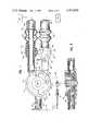
- FIG. 1is a detailed plan view, taken partly in longitudinal section, of a peritoneal dialysis set in accordance with this invention, with some portions thereof being shown schematically and in reduced scale.
- FIG. 2is a fragmentary, longitudinal sectional view of the multiple-way valve of the set of FIG. 1.
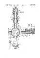
- FIG. 3is an enlarged, longitudinal sectional view of a portion of the set of this invention, showing a threaded conduit in connection with the coupler means, prior to rupturing of the frangible diaphragm by the spike.
- FIG. 4is a similar longitudinal sectional view of the structure of FIG. 3, after rupturing of the diaphragm by means of the spike.
- FIG. 5is a fragmentary elevational view of part of an alternate set of this invention, taken partly in longitudinal section, showing the arrangement of the various convolutions of the elongated ultraviolet light element relative to the multiple-way valve and connected conduits when the multiple-way valve is positioned in the ultraviolet light applicator.
- FIG. 6is a plan view of the specific ultraviolet light element utilized in the embodiment of FIG. 5.
- FIG. 7is a view of the ultraviolet light element of FIG. 6, taken along line 7--7 of FIG. 6.
- FIG. 8is a view of the ultraviolet light element, taken along line 8--8 of FIG. 6.
- FIG. 9is a plan view of the ultraviolet light applicator utilized in this invention, containing one of the sets disclosed herein.
- FIG. 10is a front elevational view of the ultraviolet light applicator of FIG. 9.
- FIG. 11is a side elevational view of the ultraviolet light applicator of FIG. 9.
- FIG. 12is a detailed plan view, taken partly in longitudinal section, of the peritoneal dialysis set shown partially in FIG. 5, with some parts shown schematically.
- FIG. 13is a fragmentary, longitudinal sectional view of the multiple-way valve of the set of FIG. 12, taken along line 13--13 of FIG. 12.
- a connector valve 11is shown, being made in accordance with this invention to facilitate repeated connection and disconnection during peritoneal dialysis procedures, while substantially suppressing the risk of transmitting infectious bacteria into the peritoneal cavity.
- Catheter 10may be surgically implanted into the peritoneal cavity of the patient, with connector member 12 of conventional design being carried at an end thereof.
- Connector member 12 and catheter 10may be constructed to be a generally permanent implant for the patient, with the connector 12 being preferably made of metal such as titanium for example, and catheter 10 being of durable silicone rubber for permanence and long life.
- Tubing 20permanently communicates with ultraviolet antimicrobial connector valve 11 as shown, with tubing 20 being sealed to port member 21, which may be an integral part of connector valve 11.
- a second connector 14is provided, being optionally made of thermoplastic material and proportioned to form a sealed connection with connector member 12, which is carried at the end of catheter 10.
- connectors 12 and 14may be of the design disclosed in Dennehey, et al. U.S. application Ser. No. 187,008, filed Sept. 15, 1980.
- tubing 20 and connector valve 11will be connected to connector member 12 at a clinic or a hospital, with the connection operation being performed under aseptic conditions.
- Tubing 20 and connector valve 11are then used on a frequent basis for a period of time, for example, about a month without disconnection of connector member 12 and second connector 14.
- connectors 12, 14are disconnected, once again at the clinic under aseptic conditions, and a fresh set comprising connector valve 11, tubing 20, and connector 14 are connected under the same aseptic conditions to connector member 12.
- the relatively inexpensive set comprising tubing 20 and connector valve 11may be subjected to ultraviolet radiation several times a day for a period of about a month, then being replaced before damage caused by the ultraviolet radiation to the material of connector valve 11 and other parts becomes excessive.
- the ultraviolet radiation techniquemay be performed in the home by the patient or his family in the period between visits to the clinic when the connection between connector members 12 and 14 is made. This assures an antimicrobial connection with the bags of solution and drainage bags for frequent peritoneal dialysis solution exchanges after the user has been trained, without the need for the constant attention of a physician or a trained nurse.
- connector valve 11comprises a housing 23, which may be made of a generally ultraviolet transmissive material such as KEL-F. Housing 23 further defines a pair of connector arms 24, 26 which may project outwardly from housing 23 at any desired angle, but preferably to form a parallel connection with tubing 20 as shown in FIGS. 1 and 2, a T connection as shown in FIGS. 12 and 13, or alternatively, a Y connection.
- housing 23may be made of a generally ultraviolet transmissive material such as KEL-F.
- Housing 23further defines a pair of connector arms 24, 26 which may project outwardly from housing 23 at any desired angle, but preferably to form a parallel connection with tubing 20 as shown in FIGS. 1 and 2, a T connection as shown in FIGS. 12 and 13, or alternatively, a Y connection.
- Connector arms 24, 26each comprise generally rigid tubular structures defining a receptacle at their outer ends having helical female threads 28 proportioned to receive a penetrating coupler 30 which, in turn, defines projecting helical threads 32 to mate with threads 28 for sealing a penetrating coupler 30 to either connector arm 24 or 26.
- Each of penetrating couplers 30is solvent sealed, heat sealed, or the like to flexible tubing 34, which may be made of polyvinyl chloride or the like.
- Tubing 34may connect to a sealed container 36, 36a which may be of conventional design.
- connector valve 11is accordingly in flow connection through each of its connector arms 24, 26 to separate containers 36, 36a.
- container 36amay serve as a source of peritoneal dialysis solution, while the other of the containers may be empty, and serves as a receptacle for spent peritoneal dialysis solution.
- container 36amay be a collapsible bag which the patient can carry under his clothes, or alternatively, the patient can disconnect bags 36, 36a and cover the ports of connector valve 11 with protective caps.
- Each of the penetrating couplers 30has a diaphragm 38, preferably at its inner end, as shown.
- Freely movable, hollow spike member 40is also provided in each of the coupler members 30.
- Hollow spike member 40may be pushed inwardly by manual manipulation of plastic bellows portions 42 of tubing 34, to cause the pointed end of spike 40 to rupture diaphragm 38, when it is desired to open a connection between container 36 and connector 11.
- Connector valve 11defines a preferably elastomeric stopcock seal member 44, which is a rotatable member of generally circular structure, fitting within cylindrical housing 23 as part of connector valve 11, and carried by rotatable outer closure 47. Projections 48 provide hermetic sliding sealing contact between member 44 and housing 23.
- Groove 50is defined by one face of stopcock seal member 44, to rotate with the rotation of the seal member 44, to provide an on-off flow connection between tubing 20 and connector arms 24, 26. Accordingly, when diaphragm 38 is ruptured, peritoneal dialysis solution from container 36 can pass through groove 50 into tubing 20, and thus into catheter 10 and the peritoneal cavity of the patient, when seal member 44 is in the position as shown in FIG. 1. This can be used during the infusion phase of CAPD. Seal member 44 may then be rotated so that no flow can pass through the connector valve 11, for example, during the dwell phase of CAPD.
- seal member 44may be rotated so that groove 50 connects between tubing 20 and connector arm 26.
- the spike 40 of connector arm 26may be advanced as in the previous manner to open a flow path between the patient's peritoneal cavity and the bag 36a connected therewith for receiving the drained peritoneal dialysis solution.
- seal member 44can be rotated again so that an additional portion of peritoneal dialysis solution may pass from a new bag 36 into the peritoneal cavity of the patient.
- seal member 44is simply rotated to isolate the appropriate connector arm 24 and/or 26 from groove 50, so that any contamination remains isolated in the respective connector arm upon opening.
- seal member 44should remain in a position to isolate that connector arm.
- the structure of this inventionmay be then reconnected to a new projecting coupler 30 and its attached container 36 or 36a. Then, before seal member 44 is rotated, connector valve 11, including connector arms 24, 26, is exposed to an ultraviolet radiation source, preferably of a wavelength of about 254 nanometers, the antimicrobial wavelength of ultraviolet light, with the radiation passing through bottom wall 52 of housing 23 and other directions. An overall dosage of about 0.6 watt ⁇ sec/cm 2 or more may be provided for each irradiation with the ultraviolet radiation also passing through the projecting connector arm walls 24, 26. As stated above, these structures may comprise an integral piece, and they are made of a material having substantial transparency to the ultraviolet radiation used. As a result of this, the area within housing 23 and projecting arms 24, 26 are subjected to the antimicrobial effect of ultraviolet radiation including the outside surfaces of penetrating couplers 30.
- tubing 20may also be made of a material as described herein and exposed to ultraviolet radiation. Otherwise, it may be made of polyvinyl chloride or the like.
- diaphragms 38should also receive the antimicrobial effect of ultraviolet radiation.
- diaphragm 38may be positioned at the outer end of coupler 30, so that all nonsterile surfaces are easily exposable to ultraviolet light. It is to be understood that the interior portions of coupler member 30 remain sterile as long as diaphragm 38 is not broken, so the couplers 30 do not have to made of an ultraviolet transparent material, although they may be so if desired.
- groove 50is exposed along its entire length to bottom wall 52 of housing 23, so it will receive antimicrobial radiation as well as the entire area inside of housing 23, although it is contemplated that contamination would not extend that far into the connector if proper procedure is used, because of the sealing areas 48.
- Stopcock seal member 44may, as shown in FIG. 2, comprise outer closure 47, attached to housing 23 by an interlocking flange structure 49 of conventional design, to provide a sealed but rotatable structure. Also, seal member 44 may be provided underneath closure 47, and attached thereto, being preferably made of silicone rubber to serve as a seal.
- the connector members of this inventionmay be of any desired design, with the multiple-way valve connector structure as shown being only one particularly contemplated design.
- luer-type connectorshaving flexible tubing that is pinched closed, with the ultraviolet radiation taking place after connection but before opening the pinch closures, constitutes another type of design in which the couplers of this invention may be used.
- internal breakaway sealsmay be used of the general type shown in U.S. Pat. No. 4,181,140 in place of diaphragms 38.
- the connector of this inventionmay be utilized in procedures other than peritoneal dialysis, to facilitate the antimicrobial effect of ultraviolet radiation in other products and processes, such as parenteral solution administration in general and the like.
- Connector valves made with the materials as described in this inventionmay be reconnected and disconnected, with ultraviolet radiation providing repeated, reliable antimicrobial effect in the connector valve interior.
- the ultraviolet irradiationmay take place while spent peritoneal dialysis solution is flowing into bag 36a, to save time in the process, so that fresh peritoneal dialysis solution may pass from bag 36 into the patient's peritoneal cavity promptly after the drainage step. It is also desirable, but not necessary, for the ultraviolet irradiation to continue while the solution is passing from bag 36 into the patient's peritoneal cavity.
- FIGS. 3 and 4longitudinal sectional views of the connection between connector arm 26 and its associated coupler member 30 are shown, FIG. 3 showing spike 40 in its original configuration, and FIG. 4 showing spike 40 in its advanced configuration when a flow path is opened through the connector and coupler.
- the details of structure shownare typically similar to connector arm 24 and its associated coupler 30.
- the area of connector arm 26 which defines internal threads 28is of less thickness than the area of coupler member 30 which defines the threads 32 of the coupler member, engaging threads 28. Accordingly, there is less thickness of material in coupler arm 26 than would otherwise be present, which facilitates the transmission of ultraviolet radiation to the junction 60 between the respective threads.
- Spike member 40may also define a cut-away portion 62 at its sharpened end 64, with the sharpened end 64 defining a pointed edge at one side of spike 40, as shown, which is opposed to cut-away portion 62.
- diaphragm 38is not completely cut away from coupler means 30 as spike 40 is advanced as in FIG. 4, but retains its attachment to at least one position 66 so that the diaphragm 38 is not cut completely loose from the assembly.
- An annular stop flange 68is also defined on coupler 30, to prevent overadvancement of screw-threaded travel by the coupler, to prevent stripping of threads 28.
- coupler 30defines a slightly tapered, tubular portion 70 to sealingly fit within connector arm 26 with a luer-type seal, to assure that no contamination can enter the system while coupler 30 and connector arm 26 are in engaged relation.
- Tubular portion 70is axially spaced from screw threads 32 of the coupler member.
- the systemmay be opened by manually grasping sleeve 72 of coupler 30 and collapsing it into the configuration of FIG. 4.
- Spike 40is advanced through diaphragm 38 by the pressure of annular seat 73 against enlarged end 74 of hollow spike 40.
- Spike 40may be proportioned so that it slides through the bore of coupler member 30 with a measure of frictional resistance, so that it will be positively retained in any desired axial position, to prevent accidental withdrawal of the spike, which could release diaphragm 38 and allow it to occlude flow through the system.
- Fin members 76may be provided, for example four of such fins spaced 90° apart, as a gripping aid to aid in the coupling and uncoupling of members 26, 30.
- FIGS. 12 and 13disclose details of another embodiment of peritoneal dialysis set in accordance with this invention, in which the reference numerals are identical with the reference numerals of FIGS. 1 and 2, and point to the corresponding and similar structures of FIGS. 12 and 13.
- the set of FIGS. 12 and 13functions in a manner which is similar to the functioning of the set of FIGS. 1 and 2 as previously described, with the exception that the connector arms 24, 26 in FIGS. 12 and 13 are opposed to each other rather than parallel as in FIGS. 1 and 2.
- FIGS. 5 through 11show details of the ultraviolet irradiation apparatus which is adapted for use in conjunction with the set of FIGS. 12 and 13.
- connector valve 11is shown with connector arms 24, 26 being attached to coupler members 30.
- Valve 11 and connected structuresare positioned in an ultraviolet light applicator or "box" as disclosed in FIGS. 9 through 11.
- the applicatorincludes a casing 80, shown in phantom in FIG. 5.
- Hinged hatch means 82permits placement of the connector valve 11 and the attached arms of conduits 24, 26 into the housing 80.
- the inner surface of housing 80may be of an ultraviolet-reflecting material 84, for example, an etched aluminum coating to maximize the exposure of ultraviolet light by the contents of the applicator.
- an elongated ultraviolet light element 86is provided in the housing 80, defining a plurality of convolutions 88 through 92.
- the convolutions 88 through 92are positioned to define a channel 94 which is proportioned for receiving connector valve 11 and connector arms 26, 28 with the convolutions 88 through 92 being positioned on at least three sides of the channel, and extending substantially along the channel so that ultraviolet light is propagated from a continuum of positions along the channel.
- the ultraviolet light sourceis capable of irradiating the transversely disposed interior surfaces of the system, for example, the outer surface of each of diaphragms 38, prior to rupturing, with at least a portion of ultraviolet source 86 defining an angle to the plane of each diaphragm 38 of about 20° to 60°, for direct irradiation thereof.
- ultraviolet light element 86is elongated and propagates its ultraviolet light from a continuum of sources, there can be no nooks or crannies capable of contact with the liquid flow paths inside of valve 11 or connector arms 24, 26 which are unexposed to the ultraviolet light.
- convolution 91 of the ultraviolet light elementis positioned to irradiate ultraviolet light onto the outer, nonsterile surface of membrane 38, on the opposite side from the corresponding spike member 40 in arm 26.
- Convolution 89is similarly positioned for the irradiation of the other diaphragm 38 positioned by coupler 30 into connector arm 28 prior to rupture by spike 40.
- These convolutionsalso irradiate bottom wall 52 of connector valve 11.
- Convolutions 88 and 92irradiate the tops of coupler arms 24, 26, so that at least the great majority of the sealed connection between each coupler member and connector arms 26, 28 is irradiated.
- Convolution 90provides additional lateral ultraviolet irradiation, while the ultraviolet radiation propagated from all of the element 86 is reflected off the housing walls 80 of the applicator back to the valve 11 from a multitude of angles and directions, for complete irradiation of the interior portions thereof.
- Control knob 96is provided, communicating with interlocking projection 98 of interlocking housing portion 47, so that seal member 44, which is attached to housing portion 47, may be rotated by rotation of the control knob 96 to control the position of flow channel 50; the control knob 96 may be permanently attached to the box or detachable from the box. As shown in FIG. 5, flow channel 50 is directly exposed to ultraviolet transmission through bottom wall 52 for sterilization of the internal portions of channel 50.
- Ultraviolet light element 86is preferably of a generally h-shape when viewed along a dimension as shown in FIG. 8, and it also may be generally of a w-shape when viewed along the dimension as shown in FIG. 7.
- ultraviolet elements having more or less than five convolutionsmay also be utilized in this invention to obtain a large, multi-dimensional continuum of sources of ultraviolet radiation for having an antimicrobial effect on the connector system.
- a photocell 87is also preferred for a photocell 87 to be provided within housing 80 to measure the total energy of ultraviolet light applied in each sterilization procedure.
- the photocell meansactivates a transducer connected to the photocell to shut off the ultraviolet light element. Accordingly, the sterilizing process of this invention does not have to use a timing sequence or the like, which can be inaccurate since ultraviolet elements can significantly change the intensity of their propagation of ultraviolet radiation. Instead, the applicator can operate until the predetermined total energy of ultraviolet exposure is emitted, following which the apparatus is activated to shut off.
- connector valve 11with its arms 21, 24, 26 may be placed into housing 80 for ultraviolet irradiation, with each of connector arms 24, 26 being connected to a coupler 30 which, in turn, connects to bags 36, 36a in aseptic manner.
- tubing 20communicates with connector valve 11.
- Tubing 20terminates with coupler 14, which is aseptically connected to coupler 12 of implanted catheter 10.
- coupler 14is aseptically connected to coupler 12 of implanted catheter 10.
- Sealing member 44may then be rotated so that channel 50 communicates with no conduit, to seal off all of the conduits.
- bag 36may be retained under the clothes during the dwell phase of the peritoneal dialysis solution in the peritoneal cavity.
- the other arm 26is typically sealed under this circumstance and free of connection with a coupler 30.
- the patientis free to go about normal daily activities, with connector valve 11 and the flat bag 36 worn under his or her clothes.
- the patientAt the termination of the several hour dwell phase for the peritoneal dialysis solution, the patient is free to go about normal daily activities, with connector valve 11 and the flat bag 36 worn under his or her clothes.
- the patientcan remove connector valve 11 and bag 36 from under his or her clothes, connect a coupler and bag 36a of fresh solution to arm 26, and insert the connector valve 11 once again into housing 80 for ultraviolet irradiation.
- Sealing member 44can be moved, controlled by knob 98, once again so that channel 50 communicates between tubing 20 and arm 24, with the result that spent peritoneal dialysis solution flows from the peritoneal cavity back to bag 36, while the ultraviolet element 86 in housing 80 irradiates the entire connector valve 11 and arms 24, 26.
- the ultraviolet radiation passing into the interior of valve 11, including arms 24, 26,provides an antimicrobial effect on the enclosed areas therein, including area 100 and any other pockets of contamination that may exist, for example area 102 resulting from the rotation of seal member 44, prior to which rotation area 102 communicated with arm 26.
- knob 98is turned to rotate seal member 44 so that channel 50 communicates between connector arm 26 and tubing 20, with the result that fresh peritoneal dialysis solution from bag 36a can flow into the patient's peritoneal cavity.
- the flow connection between bag 36 and the peritoneal cavityis terminated with the seal provided by seal member 44.
- bag 36 and its associated coupler 30may be removed which, of course, exposes the interior of arm 24 to potential contamination.
- the contaminationis limited by the position of seal 44, so that it can only find its way into one or two of the pockets analogous to pockets 100, 102, which remain isolated from the then flow path communicating with the peritoneal cavity.
- connector valve 11may be removed from the ultraviolet applicator, and flat bag 36a and connector valve 11 may be placed under the clothes of the patient, for him to resume his normal activities until it is time to repeat the process, utilizing bag 36a as the drainage bag.
- a new bag 36 and coupler 30may be attached to arm 24, followed preferably by drainage from the peritoneal cavity into bag 36a simultaneously with irradiation of the system as before, so that the flow path between new bag 36 and the peritoneal cavity may be irradiated by ultraviolet light prior to its use.
Landscapes
- Health & Medical Sciences (AREA)
- Heart & Thoracic Surgery (AREA)
- Urology & Nephrology (AREA)
- Life Sciences & Earth Sciences (AREA)
- General Health & Medical Sciences (AREA)
- Anesthesiology (AREA)
- Biomedical Technology (AREA)
- Hematology (AREA)
- Emergency Medicine (AREA)
- Animal Behavior & Ethology (AREA)
- Engineering & Computer Science (AREA)
- Public Health (AREA)
- Veterinary Medicine (AREA)
- Vascular Medicine (AREA)
- Epidemiology (AREA)
- Pulmonology (AREA)
- External Artificial Organs (AREA)
- Apparatus For Disinfection Or Sterilisation (AREA)
Abstract
Description
Claims (34)
Priority Applications (19)
| Application Number | Priority Date | Filing Date | Title |
|---|---|---|---|
| US06/270,743US4412834A (en) | 1981-06-05 | 1981-06-05 | Antimicrobial ultraviolet irradiation of connector for continuous ambulatory peritoneal dialysis |
| CA000400135ACA1182143A (en) | 1981-06-05 | 1982-03-31 | Antimicrobial ultraviolet irradiation of connector for continuous ambulatory peritoneal dialysis |
| AU85252/82AAU553771B2 (en) | 1981-06-05 | 1982-04-26 | Antimicrobial ultraviolet irradiation of connector for continuous ambulatory peritoneal dialysis |
| BR8207737ABR8207737A (en) | 1981-06-05 | 1982-04-26 | ANTIMICROBIAL ULTRAVIOLET IRRADIATION OF CONNECTOR FOR PERITONEAL DIALYSIS CONTINUOUS AMBULATORY |
| PCT/US1982/000539WO1982004187A1 (en) | 1981-06-05 | 1982-04-26 | Antimicrobial ultraviolet irradiation of connector for continuous ambulatory peritoneal dialysis |
| EP85201676AEP0175428B1 (en) | 1981-06-05 | 1982-04-26 | Tube coupling member, especially for antimicrobial irradiation |
| DE8282901761TDE3278100D1 (en) | 1981-06-05 | 1982-04-26 | Antimicrobial ultraviolet irradiation of connector for continuous ambulatory peritoneal dialysis |
| EP82901761AEP0080485B1 (en) | 1981-06-05 | 1982-04-26 | Antimicrobial ultraviolet irradiation of connector for continuous ambulatory peritoneal dialysis |
| DE8585201676TDE3278779D1 (en) | 1981-06-05 | 1982-04-26 | Tube coupling member, especially for antimicrobial irradiation |
| JP57501775AJPS58501158A (en) | 1981-06-05 | 1982-04-26 | Antimicrobial UV irradiation of connectors for continuous ambulatory peritoneal dialysis |
| IL65673AIL65673A (en) | 1981-06-05 | 1982-05-03 | Ultraviolet-transmissive connector valve for continuous peritoneal dialysis |
| IL77774AIL77774A (en) | 1981-06-05 | 1982-05-03 | Coupler for connection of two tubes |
| MX192789AMX152084A (en) | 1981-06-05 | 1982-05-20 | IMPROVEMENTS IN A CONNECTING MEMBER WHICH IS TRANSPARENT IN ULTRAVIOLET RADIATION TO CREATE A SEAL DURING CONTINUOUS AMBULATORY PERITONEAL DIALYSIS |
| IT21579/82AIT1152221B (en) | 1981-06-05 | 1982-05-28 | ANTI-MICROBIAL ULTRAVIOLET IRRADIATION OF A FITTING FOR CONTINUOUS PERITONEAL DIALYSIS AMBULATORY |
| ES512764AES8306025A1 (en) | 1981-06-05 | 1982-06-01 | Antimicrobial ultraviolet irradiation of connector for continuous ambulatory peritoneal dialysis. |
| ZA823927AZA823927B (en) | 1981-06-05 | 1982-06-04 | Antimicrobial ultraviolet irradiation of connector for continuous ambulatory peritoneal dialysis |
| DK048483ADK161801C (en) | 1981-06-05 | 1983-02-04 | ANTI-MICROBIAL, ULTRAVIOLET RADIATION OF CONNECTION TO CONTINUOUS, AMBULANT PERITONEAL DIALYSIS |
| US06/469,196US4503333A (en) | 1981-06-05 | 1983-02-24 | Antimicrobial ultraviolet irradiation of connector for continuous ambulatory peritoneal dialysis |
| JP2209068AJPH03184551A (en) | 1981-06-05 | 1990-08-06 | Irradiation of antimicrobial ultraviolet ray to connector for use in continuous walking peritoneum dialysis |
Applications Claiming Priority (1)
| Application Number | Priority Date | Filing Date | Title |
|---|---|---|---|
| US06/270,743US4412834A (en) | 1981-06-05 | 1981-06-05 | Antimicrobial ultraviolet irradiation of connector for continuous ambulatory peritoneal dialysis |
Related Child Applications (1)
| Application Number | Title | Priority Date | Filing Date |
|---|---|---|---|
| US06/469,196DivisionUS4503333A (en) | 1981-06-05 | 1983-02-24 | Antimicrobial ultraviolet irradiation of connector for continuous ambulatory peritoneal dialysis |
Publications (1)
| Publication Number | Publication Date |
|---|---|
| US4412834Atrue US4412834A (en) | 1983-11-01 |
Family
ID=23032612
Family Applications (2)
| Application Number | Title | Priority Date | Filing Date |
|---|---|---|---|
| US06/270,743Expired - LifetimeUS4412834A (en) | 1981-06-05 | 1981-06-05 | Antimicrobial ultraviolet irradiation of connector for continuous ambulatory peritoneal dialysis |
| US06/469,196Expired - LifetimeUS4503333A (en) | 1981-06-05 | 1983-02-24 | Antimicrobial ultraviolet irradiation of connector for continuous ambulatory peritoneal dialysis |
Family Applications After (1)
| Application Number | Title | Priority Date | Filing Date |
|---|---|---|---|
| US06/469,196Expired - LifetimeUS4503333A (en) | 1981-06-05 | 1983-02-24 | Antimicrobial ultraviolet irradiation of connector for continuous ambulatory peritoneal dialysis |
Country Status (14)
| Country | Link |
|---|---|
| US (2) | US4412834A (en) |
| EP (2) | EP0080485B1 (en) |
| JP (2) | JPS58501158A (en) |
| AU (1) | AU553771B2 (en) |
| BR (1) | BR8207737A (en) |
| CA (1) | CA1182143A (en) |
| DE (2) | DE3278779D1 (en) |
| DK (1) | DK161801C (en) |
| ES (1) | ES8306025A1 (en) |
| IL (2) | IL65673A (en) |
| IT (1) | IT1152221B (en) |
| MX (1) | MX152084A (en) |
| WO (1) | WO1982004187A1 (en) |
| ZA (1) | ZA823927B (en) |
Cited By (65)
| Publication number | Priority date | Publication date | Assignee | Title |
|---|---|---|---|---|
| US4500788A (en)* | 1983-08-19 | 1985-02-19 | Baxter Travenol Laboratories, Inc. | Device for providing antibacterial radiation |
| US4614514A (en)* | 1983-02-16 | 1986-09-30 | M/A Com, Inc. | Microwave sterilizer |
| US4620845A (en)* | 1981-06-05 | 1986-11-04 | Popovich Robert P | Method of peritoneal dialysis involving ultraviolet radiation of dialysis apparatus |
| US4655762A (en)* | 1980-06-09 | 1987-04-07 | Rogers Phillip P | Ambulatory dialysis system and connector |
| US4655753A (en)* | 1985-11-27 | 1987-04-07 | Baxter Travenol Laboratories, Inc. | Connection device |
| US4695276A (en)* | 1984-11-06 | 1987-09-22 | Terumo Kabushiki Kaisha | Medical instrument |
| US4738668A (en)* | 1981-07-29 | 1988-04-19 | Baxter Travenol Laboratories, Inc. | Conduit connectors having antiseptic application means |
| US4769017A (en)* | 1985-04-04 | 1988-09-06 | Fath John J | Self-sealing infusion manifold and catheter connector |
| US4801091A (en)* | 1988-03-31 | 1989-01-31 | Sandvik Arne P | Pulsating hot and cold shower head |
| US5279605A (en)* | 1989-05-03 | 1994-01-18 | Baxter International Inc. | Frangible spike connector for a solution bag |
| US5738086A (en)* | 1994-02-02 | 1998-04-14 | Baxter International Inc. | Method of installing an anti-siphon flow restricter for a nebulizer |
| US6440095B1 (en) | 1993-12-20 | 2002-08-27 | Dsu Medical Corporation | Pump segment having connected parallel branch line |
| US6565525B1 (en)* | 1997-05-15 | 2003-05-20 | Vasca, Inc. | Valve port assembly with interlock |
| US20030191356A1 (en)* | 2002-04-08 | 2003-10-09 | Steve Moreci | Medical devices |
| US6736797B1 (en)* | 1998-06-19 | 2004-05-18 | Unomedical A/S | Subcutaneous infusion set |
| US20040230162A1 (en)* | 2003-05-14 | 2004-11-18 | Tan Sharon Mi Lyn | System for providing a medical device with anti-microbial properties |
| WO2005082437A1 (en) | 2004-02-27 | 2005-09-09 | Iperboreal Pharma S.R.L. | Apparatus for applying and removing closing means from an end portion of a tubular element and the use thereof in peritoneal dialysis |
| US20050215976A1 (en)* | 2002-07-09 | 2005-09-29 | Claes Wallen | Device for injecting medical substances |
| US20050279692A1 (en)* | 2004-06-22 | 2005-12-22 | Luca Caleffi | Transducer-protector device for medical apparatus |
| US20080065043A1 (en)* | 2004-09-08 | 2008-03-13 | Guerbet | Storage Assembly for Contrast Media |
| US20090012451A1 (en)* | 2007-07-05 | 2009-01-08 | Baxter International Inc. | Peritoneal dialysis patient connection system |
| US20090012459A1 (en)* | 2007-07-05 | 2009-01-08 | Baxter International Inc. | Peritoneal dialysis patient connection system using ultraviolet light emitting diodes |
| US20090012455A1 (en)* | 2007-07-05 | 2009-01-08 | Baxter International Inc. | Dialysis system having supply container autoconnection |
| WO2009154903A2 (en) | 2008-06-20 | 2009-12-23 | Baxter International Inc | Methods for processing substrates having an antimicrobial coating |
| CN100581599C (en)* | 2004-02-27 | 2010-01-20 | 爱普博瑞尔制药有限公司 | Apparatus for applying and removing closing means from an end portion of a tubular element and the use thereof in peritoneal dialysis |
| US20100130920A1 (en)* | 2008-11-21 | 2010-05-27 | Baxter International Inc. | Dialysis machine having auto-connection system with roller occluder |
| WO2010104806A1 (en) | 2009-03-09 | 2010-09-16 | Baxter International Inc. | Methods for processing substrates having an antimicrobial coating |
| US20110064608A1 (en)* | 2009-09-15 | 2011-03-17 | Baxter International Inc. | Dialysis connector and cap compatible with gas sterilization |
| US20110085936A1 (en)* | 2009-03-31 | 2011-04-14 | Eyal Haytman | Methods and Apparatus for Reducing Count of Infectious Agents in Intravenous Access Systems |
| US20110284773A1 (en)* | 2010-05-19 | 2011-11-24 | Pugh Randall B | Germicidal bulb disinfection base for ophthalmic lenses |
| US8277826B2 (en) | 2008-06-25 | 2012-10-02 | Baxter International Inc. | Methods for making antimicrobial resins |
| US8585681B2 (en) | 2010-05-10 | 2013-11-19 | Puracath Medical, Inc. | Systems and methods for increasing sterilization during peritoneal dialysis |
| EP2740355A1 (en) | 2012-10-30 | 2014-06-11 | Baxter International Inc. | Antimicrobial coating containing quaternary ammonium resin and its regeneration |
| US8753561B2 (en) | 2008-06-20 | 2014-06-17 | Baxter International Inc. | Methods for processing substrates comprising metallic nanoparticles |
| US8764702B2 (en) | 2007-07-05 | 2014-07-01 | Baxter International Inc. | Dialysis system having dual patient line connection and prime |
| US20140360594A1 (en)* | 2007-07-05 | 2014-12-11 | Baxter International Inc. | Medical fluid machine with supply autoconnection |
| US8980174B2 (en) | 2011-05-13 | 2015-03-17 | Bactriblue, Ltd. | Methods and apparatus for reducing count of infectious agents in intravenous access system |
| US20150352348A1 (en)* | 2014-06-05 | 2015-12-10 | Douglas Murphy-Chutorian | Transfer catheter for ultraviolet disinfection |
| US20150367355A1 (en)* | 2013-01-24 | 2015-12-24 | Lixil Corporation | Pulse shower device |
| US9242034B2 (en)* | 2007-07-05 | 2016-01-26 | Baxter International Inc. | Dialysis system having autoconnection |
| US9282796B2 (en) | 2010-05-19 | 2016-03-15 | Johnson & Johnson Vision Care, Inc. | UV radiation control for disinfecting of ophthalmic lenses |
| US9295742B2 (en) | 2012-04-16 | 2016-03-29 | Puracath Medical, Inc. | System and method for disinfecting a catheter system |
| EP3009155A1 (en) | 2007-07-05 | 2016-04-20 | Baxter International Inc. | Dialysis system having disposable cassette and interface therefore |
| WO2016149645A1 (en) | 2015-03-18 | 2016-09-22 | Puracath Medical, Inc. | Catheter connection system for ultraviolet light disinfection |
| US9492574B2 (en) | 2013-01-29 | 2016-11-15 | Puracath Medical, Inc. | Apparatus for disinfecting or sterilizing a catheter and method of use |
| US9649436B2 (en) | 2011-09-21 | 2017-05-16 | Bayer Healthcare Llc | Assembly method for a fluid pump device for a continuous multi-fluid delivery system |
| US20170203025A1 (en)* | 2011-03-23 | 2017-07-20 | Nxstage Medical, Inc. | Peritoneal Dialysis Systems, Devices, and Methods |
| US9795704B2 (en) | 2010-05-19 | 2017-10-24 | Johnson & Johnson Vision Care, Inc | Ophthalmic lens disinfecting base |
| US9808647B2 (en) | 2012-04-05 | 2017-11-07 | Veritas Medical, L.L.C. | Methods and apparatus to inactivate infectious agents on a catheter residing in a body cavity |
| WO2018013572A1 (en)* | 2016-07-11 | 2018-01-18 | Puracath Medical, Inc. | Catheter connection system for ultraviolet light disinfection |
| US9872978B1 (en) | 2017-06-21 | 2018-01-23 | Inikoa Medical, Inc. | Disinfecting methods and apparatus |
| CN108355189A (en)* | 2018-02-07 | 2018-08-03 | 温州市中心医院 | A kind of peritoneum dialysis catheter |
| US10307612B2 (en) | 2012-04-05 | 2019-06-04 | Light Line Medical, Inc. | Methods and apparatus to deliver therapeutic, non-ultraviolet electromagnetic radiation to inactivate infectious agents and/or to enhance healthy cell growth via a catheter residing in a body cavity |
| US10507319B2 (en) | 2015-01-09 | 2019-12-17 | Bayer Healthcare Llc | Multiple fluid delivery system with multi-use disposable set and features thereof |
| US10765767B2 (en) | 2018-06-19 | 2020-09-08 | Inikoa Medical, Inc. | Disinfecting methods and apparatus |
| US10894173B2 (en) | 2012-04-05 | 2021-01-19 | Light Line Medical, Inc. | Methods and apparatus to deliver therapeutic, non-ultraviolet electromagnetic radiation to inactivate infectious agents and/or to enhance healthy cell growth via a catheter residing in a body cavity |
| US20210322658A1 (en)* | 2020-04-16 | 2021-10-21 | Fresenius Medical Care Holdings, Inc. | Medical device having integrated sterile work platform |
| US11207454B2 (en) | 2018-02-28 | 2021-12-28 | Nxstage Medical, Inc. | Fluid preparation and treatment devices methods and systems |
| US11229728B1 (en) | 2020-08-24 | 2022-01-25 | Light Line Medical, Inc. | Method and apparatus to deliver therapeutic, non-ultraviolet electromagnetic radiation in a dialysis system |
| US11229808B2 (en) | 2012-04-05 | 2022-01-25 | Light Line Medical, Inc. | Methods and apparatus to deliver therapeutic, non-ultraviolet electromagnetic radiation versatilely via a catheter residing in a body cavity |
| US11497932B2 (en) | 2012-04-05 | 2022-11-15 | Light Line Medical, Inc. | Electromagnetic radiation delivery and monitoring system and methods for preventing, reducing and/or eliminating catheter-related infections during institutional or in-home use |
| US12048791B2 (en) | 2017-06-24 | 2024-07-30 | Nxstage Medical, Inc. | Peritoneal dialysis fluid preparation and/or treatment devices methods and systems |
| US12115295B2 (en) | 2021-12-20 | 2024-10-15 | Fresenius Medical Care Holdings, Inc. | Hemodialysis system including ultraviolet chamber(s) |
| WO2024228677A1 (en)* | 2023-05-03 | 2024-11-07 | Awak Technologies Pte Ltd | Sterilization device for a fluidic connector for use with a dialysis apparatus |
| US12214097B2 (en) | 2017-12-22 | 2025-02-04 | Inikoa Medical, Inc. | Disinfecting methods and apparatus |
Families Citing this family (25)
| Publication number | Priority date | Publication date | Assignee | Title |
|---|---|---|---|---|
| IE54194B1 (en)* | 1982-06-30 | 1989-07-05 | Boots Co Plc | Medical connector |
| US4882496A (en)* | 1988-04-29 | 1989-11-21 | Baxter International Inc. | Apparatus for exchanging and irradiating tubing connections |
| US5184020A (en)* | 1989-10-26 | 1993-02-02 | Hearst David P | Device and method for photoactivation |
| NZ271896A (en) | 1993-09-17 | 1998-02-26 | Univ Hawaii | Pest treatment chamber; apparatus for killing pests on or in flowers, fruit or vegetable commodities; use of hot air with a relative humidity of 30-85% |
| US6146600A (en)* | 1993-09-17 | 2000-11-14 | University Of Hawaii | Side body disingestation chamber |
| SE504779C2 (en)* | 1994-09-07 | 1997-04-21 | Danfoss As | Sampling device with membrane and membrane holder |
| US5768853A (en)* | 1996-02-15 | 1998-06-23 | Purepulse Technologies, Inc. | Deactivation of microorganisms |
| JP3121302B2 (en)* | 1997-11-04 | 2000-12-25 | 三共電気株式会社 | Irradiation type sterilizer |
| DE29809867U1 (en)* | 1998-06-04 | 1998-09-24 | Büttner, Klaus, Dipl.-Ing., 25336 Klein Nordende | UV lamp for hemodialysis |
| KR20010099905A (en) | 1998-12-23 | 2001-11-09 | 리차드 에이. 에크하드트 | Method and apparatus for sterilizing small objects |
| KR20030072363A (en)* | 2000-12-14 | 2003-09-13 | 유브이-솔루션즈, 엘엘씨. | Method and apparatus for rapidly sterilizing small objects |
| WO2002076513A1 (en)* | 2001-03-27 | 2002-10-03 | Uv-Solutions, Llc. | Method and apparatus for rapidly sterilizing irregularly-shaped objects |
| WO2002102419A2 (en) | 2001-06-15 | 2002-12-27 | Uv-Solutions, Llc. | Method and apparatus for sterilizing or disinfecting a region through a bandage |
| US9348975B2 (en)* | 2008-05-02 | 2016-05-24 | Baxter International Inc. | Optimizing therapy outcomes for peritoneal dialysis |
| US8882700B2 (en) | 2008-05-02 | 2014-11-11 | Baxter International Inc. | Smart patient transfer set for peritoneal dialysis |
| US8431074B2 (en)* | 2008-07-29 | 2013-04-30 | Mallinckrodt Llc | Ultraviolet tubing and tip sterilizer |
| US20100130918A1 (en)* | 2008-11-21 | 2010-05-27 | Baxter International Inc. | Systems and methods for removing air from supply containers and associated fill tubing |
| EP2391404B1 (en) | 2009-01-30 | 2013-01-16 | Baxter International Inc. | Transfer sets for therapy optimization |
| WO2013136888A1 (en)* | 2012-03-12 | 2013-09-19 | テルモ株式会社 | Blood-flow-path switching device and blood-bag system |
| US10850018B2 (en)* | 2015-12-24 | 2020-12-01 | Ellen Medical Devices Pty Ltd. | Treatment fluid preparation system |
| EP3216487B1 (en) | 2016-03-07 | 2020-05-06 | Fenwal, Inc. | System and method for creating sterile connections using ultraviolet light |
| US10688207B2 (en) | 2016-08-02 | 2020-06-23 | C. R. Bard, Inc. | High energy visible light-based disinfection of medical components |
| US12280231B2 (en) | 2020-04-02 | 2025-04-22 | Fenwal, Inc. | Reversible sterile connection system |
| EP4245324A3 (en)* | 2022-03-14 | 2023-11-29 | Fenwal, Inc. | Hand-held sterile connection device, system, and method of use |
| EP4245353A1 (en) | 2022-03-14 | 2023-09-20 | Fenwal, Inc. | Reversible sterile connection system |
Citations (23)
| Publication number | Priority date | Publication date | Assignee | Title |
|---|---|---|---|---|
| US2145196A (en)* | 1933-11-16 | 1939-01-24 | Hygrade Sylvania Corp | Apparatus for treating foodstuffs |
| US3391951A (en)* | 1966-12-07 | 1968-07-09 | Weatherhead Co | Diaphragm sealed coupling |
| US3626938A (en)* | 1970-06-30 | 1971-12-14 | Antonio A Versaci | Hemodialysis shunt valve device with body connecting means |
| US3780736A (en)* | 1972-10-20 | 1973-12-25 | A Chen | Surgical valve assembly for urinary bladder irrigation and drainage |
| US3814680A (en)* | 1971-05-06 | 1974-06-04 | Meltzer H | Process and apparatus for purification of materials |
| US3916950A (en)* | 1972-11-03 | 1975-11-04 | Stanadyne Inc | Seal construction |
| US3926556A (en)* | 1973-05-30 | 1975-12-16 | Raymond Marcel Gut Boucher | Biocidal electromagnetic synergistic process |
| US3955922A (en)* | 1975-06-06 | 1976-05-11 | Robert J. Patch | Sterilizer for bathroom articles |
| US3957082A (en)* | 1974-09-26 | 1976-05-18 | Arbrook, Inc. | Six-way stopcock |
| US3986508A (en)* | 1973-08-22 | 1976-10-19 | Abcor, Inc. | Sterilizable, medical connector for blood processing |
| US3994686A (en)* | 1974-03-11 | 1976-11-30 | Ab Ziristor | Helical bifilar wound ultra-violet sterilization for tube shaped material |
| US4056116A (en)* | 1976-09-08 | 1977-11-01 | Baxter Travenol Laboratories, Inc. | Valve for interconnecting sterile containers and the like |
| US4063890A (en)* | 1973-02-12 | 1977-12-20 | Baron Neville A | Method and apparatus for sterilizing and storing contact lenses |
| US4069153A (en)* | 1975-10-28 | 1978-01-17 | American Sterilizer Company | Method of destroying pyrogens |
| US4080965A (en)* | 1976-09-30 | 1978-03-28 | Baxter Travenol Laboratories, Inc. | In-line cannula valve assembly |
| US4121107A (en)* | 1974-04-10 | 1978-10-17 | Bbc Brown, Boveri & Company Limited | Apparatus for automatic low-bacteria to aseptic filling and packing of foodstuffs |
| US4141686A (en)* | 1977-03-24 | 1979-02-27 | Lewis James H | Disposable liquid sterilizer unit |
| US4173234A (en)* | 1977-11-25 | 1979-11-06 | Waterous Company | Transfer valve |
| US4201917A (en)* | 1977-07-23 | 1980-05-06 | Alfred Graentzel | Apparatus for irradiation of fluids |
| US4219221A (en)* | 1979-02-26 | 1980-08-26 | General Electric Company | Coupling for rejoining sealed tubing |
| US4242310A (en)* | 1978-11-13 | 1980-12-30 | Baxter Travenol Laboratories, Inc. | Sterile connection apparatus |
| US4291701A (en)* | 1978-07-11 | 1981-09-29 | Bell & Howell Company | Pressure transducing and methods and apparatus for filling a cavity |
| US4346703A (en)* | 1979-01-23 | 1982-08-31 | Baxter Travenol Laboratories, Inc. | Solution container for continuous ambulatory peritoneal dialysis |
Family Cites Families (7)
| Publication number | Priority date | Publication date | Assignee | Title |
|---|---|---|---|---|
| US1896379A (en)* | 1930-11-17 | 1933-02-07 | James C Ross | Sterilizing apparatus |
| US3057350A (en)* | 1958-06-27 | 1962-10-09 | Baxter Don Inc | Administration set |
| DE2119961C3 (en)* | 1971-04-23 | 1982-09-30 | Georg 4902 Bad Salzuflen Horstmann | Device for sterilizing flowing liquids and gases |
| GB1428391A (en)* | 1972-06-23 | 1976-03-17 | Avon Medicals | Couplings |
| DE2320990A1 (en)* | 1973-04-19 | 1974-10-31 | Hoenke Erwin | DEVICE FOR STERILIZING BACTERICIDAL RADIATION OF OBJECTS |
| US4177835A (en)* | 1975-01-06 | 1979-12-11 | Paley Hyman W | Plastic manifold assembly |
| CA1155725A (en)* | 1979-01-23 | 1983-10-25 | T. Michael Dennehey | Solution container for continuous ambulatory peritoneal dialysis |
- 1981
- 1981-06-05USUS06/270,743patent/US4412834A/ennot_activeExpired - Lifetime
- 1982
- 1982-03-31CACA000400135Apatent/CA1182143A/ennot_activeExpired
- 1982-04-26JPJP57501775Apatent/JPS58501158A/enactiveGranted
- 1982-04-26EPEP82901761Apatent/EP0080485B1/ennot_activeExpired
- 1982-04-26EPEP85201676Apatent/EP0175428B1/ennot_activeExpired
- 1982-04-26AUAU85252/82Apatent/AU553771B2/ennot_activeCeased
- 1982-04-26WOPCT/US1982/000539patent/WO1982004187A1/enactiveIP Right Grant
- 1982-04-26DEDE8585201676Tpatent/DE3278779D1/ennot_activeExpired
- 1982-04-26BRBR8207737Apatent/BR8207737A/ennot_activeIP Right Cessation
- 1982-04-26DEDE8282901761Tpatent/DE3278100D1/ennot_activeExpired
- 1982-05-03ILIL65673Apatent/IL65673A/ennot_activeIP Right Cessation
- 1982-05-03ILIL77774Apatent/IL77774A/ennot_activeIP Right Cessation
- 1982-05-20MXMX192789Apatent/MX152084A/enunknown
- 1982-05-28ITIT21579/82Apatent/IT1152221B/enactive
- 1982-06-01ESES512764Apatent/ES8306025A1/ennot_activeExpired
- 1982-06-04ZAZA823927Apatent/ZA823927B/enunknown
- 1983
- 1983-02-04DKDK048483Apatent/DK161801C/ennot_activeIP Right Cessation
- 1983-02-24USUS06/469,196patent/US4503333A/ennot_activeExpired - Lifetime
- 1990
- 1990-08-06JPJP2209068Apatent/JPH03184551A/enactiveGranted
Patent Citations (23)
| Publication number | Priority date | Publication date | Assignee | Title |
|---|---|---|---|---|
| US2145196A (en)* | 1933-11-16 | 1939-01-24 | Hygrade Sylvania Corp | Apparatus for treating foodstuffs |
| US3391951A (en)* | 1966-12-07 | 1968-07-09 | Weatherhead Co | Diaphragm sealed coupling |
| US3626938A (en)* | 1970-06-30 | 1971-12-14 | Antonio A Versaci | Hemodialysis shunt valve device with body connecting means |
| US3814680A (en)* | 1971-05-06 | 1974-06-04 | Meltzer H | Process and apparatus for purification of materials |
| US3780736A (en)* | 1972-10-20 | 1973-12-25 | A Chen | Surgical valve assembly for urinary bladder irrigation and drainage |
| US3916950A (en)* | 1972-11-03 | 1975-11-04 | Stanadyne Inc | Seal construction |
| US4063890A (en)* | 1973-02-12 | 1977-12-20 | Baron Neville A | Method and apparatus for sterilizing and storing contact lenses |
| US3926556A (en)* | 1973-05-30 | 1975-12-16 | Raymond Marcel Gut Boucher | Biocidal electromagnetic synergistic process |
| US3986508A (en)* | 1973-08-22 | 1976-10-19 | Abcor, Inc. | Sterilizable, medical connector for blood processing |
| US3994686A (en)* | 1974-03-11 | 1976-11-30 | Ab Ziristor | Helical bifilar wound ultra-violet sterilization for tube shaped material |
| US4121107A (en)* | 1974-04-10 | 1978-10-17 | Bbc Brown, Boveri & Company Limited | Apparatus for automatic low-bacteria to aseptic filling and packing of foodstuffs |
| US3957082A (en)* | 1974-09-26 | 1976-05-18 | Arbrook, Inc. | Six-way stopcock |
| US3955922A (en)* | 1975-06-06 | 1976-05-11 | Robert J. Patch | Sterilizer for bathroom articles |
| US4069153A (en)* | 1975-10-28 | 1978-01-17 | American Sterilizer Company | Method of destroying pyrogens |
| US4056116A (en)* | 1976-09-08 | 1977-11-01 | Baxter Travenol Laboratories, Inc. | Valve for interconnecting sterile containers and the like |
| US4080965A (en)* | 1976-09-30 | 1978-03-28 | Baxter Travenol Laboratories, Inc. | In-line cannula valve assembly |
| US4141686A (en)* | 1977-03-24 | 1979-02-27 | Lewis James H | Disposable liquid sterilizer unit |
| US4201917A (en)* | 1977-07-23 | 1980-05-06 | Alfred Graentzel | Apparatus for irradiation of fluids |
| US4173234A (en)* | 1977-11-25 | 1979-11-06 | Waterous Company | Transfer valve |
| US4291701A (en)* | 1978-07-11 | 1981-09-29 | Bell & Howell Company | Pressure transducing and methods and apparatus for filling a cavity |
| US4242310A (en)* | 1978-11-13 | 1980-12-30 | Baxter Travenol Laboratories, Inc. | Sterile connection apparatus |
| US4346703A (en)* | 1979-01-23 | 1982-08-31 | Baxter Travenol Laboratories, Inc. | Solution container for continuous ambulatory peritoneal dialysis |
| US4219221A (en)* | 1979-02-26 | 1980-08-26 | General Electric Company | Coupling for rejoining sealed tubing |
Non-Patent Citations (4)
| Title |
|---|
| "Frozen Red Cell Outdating", DHEW Publication No. (NIH) 76-1004 dated Mar. 14, 1975.* |
| Abstract by Joshi et al., entitled "In Vitro Studies of Surface Sterilization of Continuous Ambulatory Peritoneal Dialysis Tubing Using Ultraviolet Light", Kidney International Official Journal of the International Society of Nephrology, vol. 1, Jan. 1981.* |
| Eisenger article from Clinical Nephrology, vol. 14, No. 1 1980, pp. 42-44.* |
| German article entitled "The sterilization of Medical Plastic Substances by Ultraviolet Rays", Strahlentherapie 111, 626-631 (1960) (English translation).* |
Cited By (145)
| Publication number | Priority date | Publication date | Assignee | Title |
|---|---|---|---|---|
| US4655762A (en)* | 1980-06-09 | 1987-04-07 | Rogers Phillip P | Ambulatory dialysis system and connector |
| US4620845A (en)* | 1981-06-05 | 1986-11-04 | Popovich Robert P | Method of peritoneal dialysis involving ultraviolet radiation of dialysis apparatus |
| US4738668A (en)* | 1981-07-29 | 1988-04-19 | Baxter Travenol Laboratories, Inc. | Conduit connectors having antiseptic application means |
| US4614514A (en)* | 1983-02-16 | 1986-09-30 | M/A Com, Inc. | Microwave sterilizer |
| US4500788A (en)* | 1983-08-19 | 1985-02-19 | Baxter Travenol Laboratories, Inc. | Device for providing antibacterial radiation |
| US4695276A (en)* | 1984-11-06 | 1987-09-22 | Terumo Kabushiki Kaisha | Medical instrument |
| US4769017A (en)* | 1985-04-04 | 1988-09-06 | Fath John J | Self-sealing infusion manifold and catheter connector |
| US4655753A (en)* | 1985-11-27 | 1987-04-07 | Baxter Travenol Laboratories, Inc. | Connection device |
| US4801091A (en)* | 1988-03-31 | 1989-01-31 | Sandvik Arne P | Pulsating hot and cold shower head |
| US5279605A (en)* | 1989-05-03 | 1994-01-18 | Baxter International Inc. | Frangible spike connector for a solution bag |
| US6440095B1 (en) | 1993-12-20 | 2002-08-27 | Dsu Medical Corporation | Pump segment having connected parallel branch line |
| US5738086A (en)* | 1994-02-02 | 1998-04-14 | Baxter International Inc. | Method of installing an anti-siphon flow restricter for a nebulizer |
| US6565525B1 (en)* | 1997-05-15 | 2003-05-20 | Vasca, Inc. | Valve port assembly with interlock |
| US6736797B1 (en)* | 1998-06-19 | 2004-05-18 | Unomedical A/S | Subcutaneous infusion set |
| US7232429B2 (en)* | 2002-04-08 | 2007-06-19 | Boston Scientific Corporation | Medical devices |
| US20030191356A1 (en)* | 2002-04-08 | 2003-10-09 | Steve Moreci | Medical devices |
| US20050215976A1 (en)* | 2002-07-09 | 2005-09-29 | Claes Wallen | Device for injecting medical substances |
| US8491563B2 (en)* | 2002-07-09 | 2013-07-23 | Carmel Pharma Ab | Device for injecting medical substances |
| US7195615B2 (en)* | 2003-05-14 | 2007-03-27 | Boston Scientific Scimed, Inc. | System for providing a medical device with anti-microbial properties |
| US20040230162A1 (en)* | 2003-05-14 | 2004-11-18 | Tan Sharon Mi Lyn | System for providing a medical device with anti-microbial properties |
| CN100581599C (en)* | 2004-02-27 | 2010-01-20 | 爱普博瑞尔制药有限公司 | Apparatus for applying and removing closing means from an end portion of a tubular element and the use thereof in peritoneal dialysis |
| WO2005082437A1 (en) | 2004-02-27 | 2005-09-09 | Iperboreal Pharma S.R.L. | Apparatus for applying and removing closing means from an end portion of a tubular element and the use thereof in peritoneal dialysis |
| US20070161946A1 (en)* | 2004-02-27 | 2007-07-12 | Iperboreal Pharma S.R.L. | Apparatus for applying and removing closing means from an end portion of a tubular element and the use thereof in peritoneal dialysis |
| US7806851B2 (en)* | 2004-02-27 | 2010-10-05 | Glomeria Therapeutics | Apparatus for applying and removing closing means from an end portion of a tubular element and the use thereof in peritoneal dialysis |
| US20050279692A1 (en)* | 2004-06-22 | 2005-12-22 | Luca Caleffi | Transducer-protector device for medical apparatus |
| US7520919B2 (en) | 2004-06-22 | 2009-04-21 | Gambro Lundia Ab | Transducer-protector device for medical apparatus |
| US20080065043A1 (en)* | 2004-09-08 | 2008-03-13 | Guerbet | Storage Assembly for Contrast Media |
| US9078806B2 (en)* | 2004-09-08 | 2015-07-14 | Guerbet | Storage assembly for contrast media |
| US20100229366A1 (en)* | 2007-07-05 | 2010-09-16 | Baxter International Inc. | Dialysis method having supply container autoconnection |
| US8469545B2 (en) | 2007-07-05 | 2013-06-25 | Baxter Healthcare Inc. | Peritoneal dialysis connection system and method for using ultraviolet light emitting diodes |
| US7736328B2 (en) | 2007-07-05 | 2010-06-15 | Baxter International Inc. | Dialysis system having supply container autoconnection |
| US9586003B2 (en)* | 2007-07-05 | 2017-03-07 | Baxter International Inc. | Medical fluid machine with supply autoconnection |
| EP3009155A1 (en) | 2007-07-05 | 2016-04-20 | Baxter International Inc. | Dialysis system having disposable cassette and interface therefore |
| US9242034B2 (en)* | 2007-07-05 | 2016-01-26 | Baxter International Inc. | Dialysis system having autoconnection |
| EP3257532A1 (en) | 2007-07-05 | 2017-12-20 | Baxter International Inc. | Dialysis system having disposable cassette and interface therefore |
| US20090012451A1 (en)* | 2007-07-05 | 2009-01-08 | Baxter International Inc. | Peritoneal dialysis patient connection system |
| US20090012455A1 (en)* | 2007-07-05 | 2009-01-08 | Baxter International Inc. | Dialysis system having supply container autoconnection |
| US11931497B2 (en) | 2007-07-05 | 2024-03-19 | Baxter International Inc. | System and method for preparing peritoneal dialysis fluid at the time of use |
| US8083709B2 (en) | 2007-07-05 | 2011-12-27 | Baxter International Inc. | Dialysis method having supply container autoconnection |
| US8157761B2 (en)* | 2007-07-05 | 2012-04-17 | Baxter International Inc. | Peritoneal dialysis patient connection system |
| US8986243B2 (en)* | 2007-07-05 | 2015-03-24 | Baxter International Inc. | Peritoneal dialysis patient connection system |
| US8197087B2 (en) | 2007-07-05 | 2012-06-12 | Baxter International Inc. | Peritoneal dialysis patient connection system using ultraviolet light emitting diodes |
| US20120209168A1 (en)* | 2007-07-05 | 2012-08-16 | Baxter Healthcare S.A. | Peritoneal dialysis patient connection system |
| US8257299B2 (en) | 2007-07-05 | 2012-09-04 | Baxter International | Dialysis methods and systems having autoconnection and autoidentification |
| US10293091B2 (en) | 2007-07-05 | 2019-05-21 | Baxter International Inc. | Dialysis system having an autoconnection mechanism |
| US11730868B2 (en) | 2007-07-05 | 2023-08-22 | Baxter International Inc. | Dialysis system having an autoconnection mechanism |
| US8911109B2 (en) | 2007-07-05 | 2014-12-16 | Baxter Healthcare Inc. | Peritoneal dialysis connection system and method for using ultraviolet light emitting diodes |
| US20140360594A1 (en)* | 2007-07-05 | 2014-12-11 | Baxter International Inc. | Medical fluid machine with supply autoconnection |
| US20090012459A1 (en)* | 2007-07-05 | 2009-01-08 | Baxter International Inc. | Peritoneal dialysis patient connection system using ultraviolet light emitting diodes |
| US8764702B2 (en) | 2007-07-05 | 2014-07-01 | Baxter International Inc. | Dialysis system having dual patient line connection and prime |
| US11311657B2 (en) | 2007-07-05 | 2022-04-26 | Baxter International Inc. | Dialysis system for mixing treatment fluid at time of use |
| US8597230B2 (en) | 2007-07-05 | 2013-12-03 | Baxter International Inc. | Dialysis system having supply container autoconnection |
| US10335532B2 (en) | 2007-07-05 | 2019-07-02 | Baxter International Inc. | Dialysis system having autoidentification mechanism |
| US8753561B2 (en) | 2008-06-20 | 2014-06-17 | Baxter International Inc. | Methods for processing substrates comprising metallic nanoparticles |
| WO2009154903A2 (en) | 2008-06-20 | 2009-12-23 | Baxter International Inc | Methods for processing substrates having an antimicrobial coating |
| US8178120B2 (en) | 2008-06-20 | 2012-05-15 | Baxter International Inc. | Methods for processing substrates having an antimicrobial coating |
| US8277826B2 (en) | 2008-06-25 | 2012-10-02 | Baxter International Inc. | Methods for making antimicrobial resins |
| US8454984B2 (en) | 2008-06-25 | 2013-06-04 | Baxter International Inc. | Antimicrobial resin compositions |
| US20100130920A1 (en)* | 2008-11-21 | 2010-05-27 | Baxter International Inc. | Dialysis machine having auto-connection system with roller occluder |
| US9044544B2 (en) | 2008-11-21 | 2015-06-02 | Baxter International Inc. | Dialysis machine having auto-connection system with roller occluder |
| US9931454B2 (en) | 2008-11-21 | 2018-04-03 | Baxter International Inc. | Dialysis machine having auto-connection system with roller occluder |
| WO2010104806A1 (en) | 2009-03-09 | 2010-09-16 | Baxter International Inc. | Methods for processing substrates having an antimicrobial coating |
| US20110085936A1 (en)* | 2009-03-31 | 2011-04-14 | Eyal Haytman | Methods and Apparatus for Reducing Count of Infectious Agents in Intravenous Access Systems |
| US8574490B2 (en) | 2009-03-31 | 2013-11-05 | Bactriblue, Ltd. | Methods and apparatus for reducing count of infectious agents in intravenous access systems |
| US8617465B2 (en) | 2009-09-15 | 2013-12-31 | Baxter International Inc. | Dialysis connector and cap compatible with gas sterilization |
| US20110064608A1 (en)* | 2009-09-15 | 2011-03-17 | Baxter International Inc. | Dialysis connector and cap compatible with gas sterilization |
| US9545470B2 (en) | 2009-09-15 | 2017-01-17 | Baxter International Inc. | Dialysis connector and cap compatible with gas sterilization |
| WO2011121585A1 (en)* | 2010-03-31 | 2011-10-06 | Bactriblue Ltd. | Methods and apparatus for reducing count of infectious agents in intravenous access systems |
| GB2492921A (en)* | 2010-03-31 | 2013-01-16 | Bactriblue Ltd | Methods and apparatus for reducing count of infectious agents in intravenous access systems |
| US8585681B2 (en) | 2010-05-10 | 2013-11-19 | Puracath Medical, Inc. | Systems and methods for increasing sterilization during peritoneal dialysis |
| US9789220B2 (en) | 2010-05-19 | 2017-10-17 | Johnson & Johnson Vision Care, Inc | Ophthalmic lens disinfecting base |
| US20110284773A1 (en)* | 2010-05-19 | 2011-11-24 | Pugh Randall B | Germicidal bulb disinfection base for ophthalmic lenses |
| US9282796B2 (en) | 2010-05-19 | 2016-03-15 | Johnson & Johnson Vision Care, Inc. | UV radiation control for disinfecting of ophthalmic lenses |
| US9872933B2 (en) | 2010-05-19 | 2018-01-23 | Johnson & Johnson Vision Care, Inc. | Light emitting diode disinfection base for ophthalmic lenses |
| US9795704B2 (en) | 2010-05-19 | 2017-10-24 | Johnson & Johnson Vision Care, Inc | Ophthalmic lens disinfecting base |
| US11690941B2 (en) | 2011-03-23 | 2023-07-04 | Nxstage Medical, Inc. | Peritoneal dialysis systems, devices, and methods |
| US11433169B2 (en) | 2011-03-23 | 2022-09-06 | Nxstage Medical, Inc. | Dialysis systems, devices, and methods |
| US11224684B2 (en) | 2011-03-23 | 2022-01-18 | Nxstage Medical, Inc. | Peritoneal dialysis systems, devices, and methods |
| US12246121B2 (en) | 2011-03-23 | 2025-03-11 | Nxstage Medical, Inc. | Peritoneal dialysis systems, devices, and methods |
| US10688235B2 (en) | 2011-03-23 | 2020-06-23 | Nxstage Medical, Inc. | Peritoneal dialysis systems, devices, and methods |
| US10688234B2 (en) | 2011-03-23 | 2020-06-23 | Nxstage Medical, Inc. | Peritoneal dialysis systems, devices, and methods |
| US10898630B2 (en) | 2011-03-23 | 2021-01-26 | Nxstage Medical, Inc. | Peritoneal dialysis systems, devices, and methods |
| US11135348B2 (en) | 2011-03-23 | 2021-10-05 | Nxstage Medical, Inc. | Peritoneal dialysis systems, devices, and methods |
| US20170203025A1 (en)* | 2011-03-23 | 2017-07-20 | Nxstage Medical, Inc. | Peritoneal Dialysis Systems, Devices, and Methods |
| US10610630B2 (en) | 2011-03-23 | 2020-04-07 | Nxstage Medical, Inc. | Peritoneal dialysis systems, devices, and methods |
| US11717601B2 (en) | 2011-03-23 | 2023-08-08 | Nxstage Medical, Inc. | Dialysis systems, devices, and methods |
| US11433170B2 (en) | 2011-03-23 | 2022-09-06 | Nxstage Medical, Inc. | Dialysis systems, devices, and methods |
| US10603424B2 (en)* | 2011-03-23 | 2020-03-31 | Nxstage Medical, Inc. | Peritoneal dialysis systems, devices, and methods |
| US8980174B2 (en) | 2011-05-13 | 2015-03-17 | Bactriblue, Ltd. | Methods and apparatus for reducing count of infectious agents in intravenous access system |
| US9649436B2 (en) | 2011-09-21 | 2017-05-16 | Bayer Healthcare Llc | Assembly method for a fluid pump device for a continuous multi-fluid delivery system |
| US9700672B2 (en) | 2011-09-21 | 2017-07-11 | Bayer Healthcare Llc | Continuous multi-fluid pump device, drive and actuating system and method |
| US11529530B2 (en) | 2012-04-05 | 2022-12-20 | Light Line Medical, Inc. | Methods and apparatus to inactivate infectious agents on a drainage catheter residing in a body cavity |
| US11497932B2 (en) | 2012-04-05 | 2022-11-15 | Light Line Medical, Inc. | Electromagnetic radiation delivery and monitoring system and methods for preventing, reducing and/or eliminating catheter-related infections during institutional or in-home use |
| US10894173B2 (en) | 2012-04-05 | 2021-01-19 | Light Line Medical, Inc. | Methods and apparatus to deliver therapeutic, non-ultraviolet electromagnetic radiation to inactivate infectious agents and/or to enhance healthy cell growth via a catheter residing in a body cavity |
| US9808647B2 (en) | 2012-04-05 | 2017-11-07 | Veritas Medical, L.L.C. | Methods and apparatus to inactivate infectious agents on a catheter residing in a body cavity |
| US11229808B2 (en) | 2012-04-05 | 2022-01-25 | Light Line Medical, Inc. | Methods and apparatus to deliver therapeutic, non-ultraviolet electromagnetic radiation versatilely via a catheter residing in a body cavity |
| US10307612B2 (en) | 2012-04-05 | 2019-06-04 | Light Line Medical, Inc. | Methods and apparatus to deliver therapeutic, non-ultraviolet electromagnetic radiation to inactivate infectious agents and/or to enhance healthy cell growth via a catheter residing in a body cavity |
| US10471277B2 (en) | 2012-04-05 | 2019-11-12 | Light Line Medical, Inc. | Methods and apparatus to inactivate infectious agents on a drainage catheter residing in a body cavity |
| US9295742B2 (en) | 2012-04-16 | 2016-03-29 | Puracath Medical, Inc. | System and method for disinfecting a catheter system |
| EP2740355A1 (en) | 2012-10-30 | 2014-06-11 | Baxter International Inc. | Antimicrobial coating containing quaternary ammonium resin and its regeneration |
| US20150367355A1 (en)* | 2013-01-24 | 2015-12-24 | Lixil Corporation | Pulse shower device |
| US9821326B2 (en)* | 2013-01-24 | 2017-11-21 | Lixil Corporation | Pulse shower device |
| US9492574B2 (en) | 2013-01-29 | 2016-11-15 | Puracath Medical, Inc. | Apparatus for disinfecting or sterilizing a catheter and method of use |
| US11007361B2 (en)* | 2014-06-05 | 2021-05-18 | Puracath Medical, Inc. | Transfer catheter for ultraviolet disinfection |
| US20150352348A1 (en)* | 2014-06-05 | 2015-12-10 | Douglas Murphy-Chutorian | Transfer catheter for ultraviolet disinfection |
| US12186466B2 (en) | 2014-06-05 | 2025-01-07 | Puracath Medical, Inc. | Transfer catheter for ultraviolet disinfection |
| US11491318B2 (en) | 2015-01-09 | 2022-11-08 | Bayer Healthcare Llc | Multiple fluid delivery system with multi-use disposable set and features thereof |
| US10507319B2 (en) | 2015-01-09 | 2019-12-17 | Bayer Healthcare Llc | Multiple fluid delivery system with multi-use disposable set and features thereof |
| US12201802B2 (en) | 2015-01-09 | 2025-01-21 | Bayer Healthcare Llc | Multiple fluid delivery system with multi-use disposable set and features thereof |
| CN108367085A (en)* | 2015-03-18 | 2018-08-03 | 普拉卡斯医疗公司 | Disinfection by ultraviolet light conduit connection systems |
| US20160271312A1 (en)* | 2015-03-18 | 2016-09-22 | Justin A. LANCE | Catheter connection system for ultraviolet light disinfection |
| US10953217B2 (en)* | 2015-03-18 | 2021-03-23 | Puracath Medical, Inc. | Catheter connection system for ultraviolet light disinfection |
| US20210252270A1 (en)* | 2015-03-18 | 2021-08-19 | Puracath Medical, Inc. | Catheter connection system for ultraviolet light disinfection |
| US11724085B2 (en)* | 2015-03-18 | 2023-08-15 | Puracath Medical, Inc. | Catheter connection system for ultraviolet light disinfection |
| WO2016149645A1 (en) | 2015-03-18 | 2016-09-22 | Puracath Medical, Inc. | Catheter connection system for ultraviolet light disinfection |
| EP3270979A4 (en)* | 2015-03-18 | 2018-12-05 | Puracath Medical, Inc. | Catheter connection system for ultraviolet light disinfection |
| CN110049790A (en)* | 2016-07-11 | 2019-07-23 | 普拉卡斯医疗公司 | Conduit connection systems for disinfection by ultraviolet light |
| US11185603B2 (en)* | 2016-07-11 | 2021-11-30 | Puracath Medical, Inc. | Catheter connection system for ultraviolet light disinfection |
| WO2018013572A1 (en)* | 2016-07-11 | 2018-01-18 | Puracath Medical, Inc. | Catheter connection system for ultraviolet light disinfection |
| WO2018236812A1 (en)* | 2017-06-21 | 2018-12-27 | Inikoa Medical, Inc. | APPARATUS AND METHODS OF DISINFECTION |
| US9895460B1 (en) | 2017-06-21 | 2018-02-20 | Inikoa Medical, Inc. | Disinfecting methods and apparatus |
| US12415004B2 (en) | 2017-06-21 | 2025-09-16 | Inikoa Medical, Ic. | Light disinfecting apparatus and methods |
| US10046070B1 (en)* | 2017-06-21 | 2018-08-14 | Inikoa Medical, Inc. | Disinfecting methods and apparatus |
| US10675368B2 (en) | 2017-06-21 | 2020-06-09 | Inikoa Medical, Inc. | Disinfecting methods and apparatus |
| US9872978B1 (en) | 2017-06-21 | 2018-01-23 | Inikoa Medical, Inc. | Disinfecting methods and apparatus |
| US11357875B2 (en) | 2017-06-21 | 2022-06-14 | Inikoa Medical, Inc. | Disinfecting methods and apparatus |
| US9974871B1 (en) | 2017-06-21 | 2018-05-22 | Inikoa Medical, Inc. | Disinfecting methods and apparatus |
| US9925285B1 (en)* | 2017-06-21 | 2018-03-27 | Inikoa Medical, Inc. | Disinfecting methods and apparatus |
| US9925286B1 (en) | 2017-06-21 | 2018-03-27 | Inikoa Medical, Inc. | Disinfecting methods and apparatus |
| US11696961B2 (en) | 2017-06-21 | 2023-07-11 | Inikoa Medical, Inc. | Apparatus for directing light through an inner lumen of a body |
| US9925287B1 (en) | 2017-06-21 | 2018-03-27 | Inikoa Medical, Inc. | Disinfecting methods and apparatus |
| US12048791B2 (en) | 2017-06-24 | 2024-07-30 | Nxstage Medical, Inc. | Peritoneal dialysis fluid preparation and/or treatment devices methods and systems |
| US12214097B2 (en) | 2017-12-22 | 2025-02-04 | Inikoa Medical, Inc. | Disinfecting methods and apparatus |
| CN108355189A (en)* | 2018-02-07 | 2018-08-03 | 温州市中心医院 | A kind of peritoneum dialysis catheter |
| US11364328B2 (en) | 2018-02-28 | 2022-06-21 | Nxstage Medical, Inc. | Fluid preparation and treatment devices methods and systems |
| US11872337B2 (en) | 2018-02-28 | 2024-01-16 | Nxstage Medical, Inc. | Fluid preparation and treatment devices methods and systems |
| US12409259B2 (en) | 2018-02-28 | 2025-09-09 | Nxstage Medical, Inc. | Fluid preparation and treatment devices methods and systems |
| US11207454B2 (en) | 2018-02-28 | 2021-12-28 | Nxstage Medical, Inc. | Fluid preparation and treatment devices methods and systems |
| US10765767B2 (en) | 2018-06-19 | 2020-09-08 | Inikoa Medical, Inc. | Disinfecting methods and apparatus |
| US12115268B2 (en) | 2018-06-19 | 2024-10-15 | Inikoa Medical, Inc. | Disinfecting methods and apparatus |
| US11484636B2 (en)* | 2020-04-16 | 2022-11-01 | Fresenius Medical Care Holdings, Inc. | Medical device having integrated sterile work platform |
| US20210322658A1 (en)* | 2020-04-16 | 2021-10-21 | Fresenius Medical Care Holdings, Inc. | Medical device having integrated sterile work platform |
| US11229728B1 (en) | 2020-08-24 | 2022-01-25 | Light Line Medical, Inc. | Method and apparatus to deliver therapeutic, non-ultraviolet electromagnetic radiation in a dialysis system |
| US12115295B2 (en) | 2021-12-20 | 2024-10-15 | Fresenius Medical Care Holdings, Inc. | Hemodialysis system including ultraviolet chamber(s) |
| WO2024228677A1 (en)* | 2023-05-03 | 2024-11-07 | Awak Technologies Pte Ltd | Sterilization device for a fluidic connector for use with a dialysis apparatus |
Also Published As
| Publication number | Publication date |
|---|---|
| CA1182143A (en) | 1985-02-05 |
| DE3278100D1 (en) | 1988-03-17 |
| DE3278779D1 (en) | 1988-08-25 |
| ZA823927B (en) | 1983-04-27 |
| EP0080485A1 (en) | 1983-06-08 |
| AU8525282A (en) | 1982-12-07 |
| JPS58501158A (en) | 1983-07-21 |
| AU553771B2 (en) | 1986-07-24 |
| IL65673A (en) | 1988-11-30 |
| ES512764A0 (en) | 1983-05-01 |
| BR8207737A (en) | 1983-05-10 |
| EP0080485A4 (en) | 1984-04-24 |
| WO1982004187A1 (en) | 1982-12-09 |
| IL77774A (en) | 1988-11-30 |
| IT1152221B (en) | 1986-12-31 |
| EP0175428A3 (en) | 1986-04-09 |
| DK161801B (en) | 1991-08-19 |
| EP0175428B1 (en) | 1988-07-20 |
| ES8306025A1 (en) | 1983-05-01 |
| EP0175428A2 (en) | 1986-03-26 |
| JPH0367711B2 (en) | 1991-10-23 |
| DK48483A (en) | 1983-02-04 |
| IL65673A0 (en) | 1982-08-31 |
| JPH038225B2 (en) | 1991-02-05 |
| DK161801C (en) | 1992-02-03 |
| DK48483D0 (en) | 1983-02-04 |
| MX152084A (en) | 1985-05-28 |
| US4503333A (en) | 1985-03-05 |
| JPH03184551A (en) | 1991-08-12 |
| EP0080485B1 (en) | 1988-02-10 |
| IT8221579A0 (en) | 1982-05-28 |
Similar Documents
| Publication | Publication Date | Title |
|---|---|---|
| US4412834A (en) | Antimicrobial ultraviolet irradiation of connector for continuous ambulatory peritoneal dialysis | |
| US4338933A (en) | Combination quick disconnect coupling and liquid cutoff valve | |
| US4366816A (en) | Combination quick disconnect coupling and fluid cutoff valve | |
| EP0497229B1 (en) | Closed system fluid connector assembly | |
| US5205821A (en) | Terminal self-releasing fluid reservoir | |
| US4432766A (en) | Conduit connectors having antiseptic application means | |
| US4950230A (en) | Method and apparatus for bagless continuous ambulatory peritoneal dialysis | |
| US4738668A (en) | Conduit connectors having antiseptic application means | |
| US4417890A (en) | Antibacterial closure | |
| US5057074A (en) | Medical container replacing method | |
| US4500788A (en) | Device for providing antibacterial radiation | |
| US12186466B2 (en) | Transfer catheter for ultraviolet disinfection | |
| IE54958B1 (en) | Connector assembly for sterile connection of two internally sterile containers of tubings | |
| US20120209168A1 (en) | Peritoneal dialysis patient connection system | |
| PT82183B (en) | APPLICATION PROCESS AND LIGHTING SYSTEM CUTTED TO STERILE COLD | |
| US4722727A (en) | Flexible container | |
| JPH08155025A (en) | Connector for medical treatment | |
| CN116077820A (en) | Flow control valve of continuous ambulatory peritoneal dialysis device and use method | |
| JPH09192216A (en) | Connector with sealed-in disinfectant and connecting tube equipped therewith | |
| JPH11253553A (en) | Medical connector device | |
| JPH05269202A (en) | Peritoneal dialyzer and dialyzate storage container for peritoneal dialysis | |
| JPH0373A (en) | Antibacterial protection apparatus, container exchanging tool for medical treatment, and exchanging method for container for medical treatment using the same device |
Legal Events
| Date | Code | Title | Description |
|---|---|---|---|
| AS | Assignment | Owner name:BAXTER TRAVENOL LABORATORIES, INC., DEERFIELD, IL Free format text:ASSIGNMENT OF ASSIGNORS INTEREST.;ASSIGNOR:KULIN, RALPH;REEL/FRAME:003915/0296 Effective date:19810520 Owner name:BAXTER TRAVENOL LABORATORIES, INC., DEERFIELD, IL Free format text:ASSIGNMENT OF ASSIGNORS INTEREST;ASSIGNOR:KULIN, RALPH;REEL/FRAME:003915/0296 Effective date:19810520 | |
| STCF | Information on status: patent grant | Free format text:PATENTED CASE | |
| AS | Assignment | Owner name:BAXTER-TRAVENOL LABORATORIES, INC., ONE BAXTER PAR Free format text:ASSIGNMENT OF ASSIGNORS INTEREST.;ASSIGNORS:MONCRIEF, JACK W.;POPOVICH, ROBERT P.;REEL/FRAME:004244/0269 Effective date:19840326 | |
| MAFP | Maintenance fee payment | Free format text:PAYMENT OF MAINTENANCE FEE, 4TH YEAR, PL 96-517 (ORIGINAL EVENT CODE: M170); ENTITY STATUS OF PATENT OWNER: LARGE ENTITY Year of fee payment:4 | |
| MAFP | Maintenance fee payment | Free format text:PAYMENT OF MAINTENANCE FEE, 8TH YEAR, PL 96-517 (ORIGINAL EVENT CODE: M171); ENTITY STATUS OF PATENT OWNER: LARGE ENTITY Year of fee payment:8 | |
| MAFP | Maintenance fee payment | Free format text:PAYMENT OF MAINTENANCE FEE, 12TH YEAR, LARGE ENTITY (ORIGINAL EVENT CODE: M185); ENTITY STATUS OF PATENT OWNER: LARGE ENTITY Year of fee payment:12 | |
| FEPP | Fee payment procedure | Free format text:PAYOR NUMBER ASSIGNED (ORIGINAL EVENT CODE: ASPN); ENTITY STATUS OF PATENT OWNER: LARGE ENTITY |