US4411651A - Device and method useful in monitoring fluid flow in a drug injector - Google Patents
Device and method useful in monitoring fluid flow in a drug injectorDownload PDFInfo
- Publication number
- US4411651A US4411651AUS06/266,835US26683581AUS4411651AUS 4411651 AUS4411651 AUS 4411651AUS 26683581 AUS26683581 AUS 26683581AUS 4411651 AUS4411651 AUS 4411651A
- Authority
- US
- United States
- Prior art keywords
- conduit
- fluid
- valve
- flow
- pump
- Prior art date
- Legal status (The legal status is an assumption and is not a legal conclusion. Google has not performed a legal analysis and makes no representation as to the accuracy of the status listed.)
- Expired - Lifetime
Links
- 239000012530fluidSubstances0.000titleclaimsabstractdescription168
- 238000012544monitoring processMethods0.000titleclaimsabstractdescription25
- 238000000034methodMethods0.000titleclaimsabstractdescription11
- 229940079593drugDrugs0.000titleabstractdescription26
- 239000003814drugSubstances0.000titleabstractdescription26
- 230000001965increasing effectEffects0.000claimsabstractdescription20
- 230000003247decreasing effectEffects0.000claimsabstractdescription18
- 238000004891communicationMethods0.000claimsdescription14
- 230000002572peristaltic effectEffects0.000claimsdescription5
- 230000001939inductive effectEffects0.000claims4
- 238000012806monitoring deviceMethods0.000abstractdescription7
- 230000000903blocking effectEffects0.000abstractdescription5
- NOESYZHRGYRDHS-UHFFFAOYSA-NinsulinChemical compoundN1C(=O)C(NC(=O)C(CCC(N)=O)NC(=O)C(CCC(O)=O)NC(=O)C(C(C)C)NC(=O)C(NC(=O)CN)C(C)CC)CSSCC(C(NC(CO)C(=O)NC(CC(C)C)C(=O)NC(CC=2C=CC(O)=CC=2)C(=O)NC(CCC(N)=O)C(=O)NC(CC(C)C)C(=O)NC(CCC(O)=O)C(=O)NC(CC(N)=O)C(=O)NC(CC=2C=CC(O)=CC=2)C(=O)NC(CSSCC(NC(=O)C(C(C)C)NC(=O)C(CC(C)C)NC(=O)C(CC=2C=CC(O)=CC=2)NC(=O)C(CC(C)C)NC(=O)C(C)NC(=O)C(CCC(O)=O)NC(=O)C(C(C)C)NC(=O)C(CC(C)C)NC(=O)C(CC=2NC=NC=2)NC(=O)C(CO)NC(=O)CNC2=O)C(=O)NCC(=O)NC(CCC(O)=O)C(=O)NC(CCCNC(N)=N)C(=O)NCC(=O)NC(CC=3C=CC=CC=3)C(=O)NC(CC=3C=CC=CC=3)C(=O)NC(CC=3C=CC(O)=CC=3)C(=O)NC(C(C)O)C(=O)N3C(CCC3)C(=O)NC(CCCCN)C(=O)NC(C)C(O)=O)C(=O)NC(CC(N)=O)C(O)=O)=O)NC(=O)C(C(C)CC)NC(=O)C(CO)NC(=O)C(C(C)O)NC(=O)C1CSSCC2NC(=O)C(CC(C)C)NC(=O)C(NC(=O)C(CCC(N)=O)NC(=O)C(CC(N)=O)NC(=O)C(NC(=O)C(N)CC=1C=CC=CC=1)C(C)C)CC1=CN=CN1NOESYZHRGYRDHS-UHFFFAOYSA-N0.000description12
- 230000007423decreaseEffects0.000description7
- 238000010586diagramMethods0.000description7
- 102000004877InsulinHuman genes0.000description6
- 108090001061InsulinProteins0.000description6
- 229940125396insulinDrugs0.000description6
- 230000001360synchronised effectEffects0.000description4
- 239000004020conductorSubstances0.000description3
- 230000008878couplingEffects0.000description3
- 238000010168coupling processMethods0.000description3
- 238000005859coupling reactionMethods0.000description3
- 238000002347injectionMethods0.000description3
- 239000007924injectionSubstances0.000description3
- 238000005259measurementMethods0.000description3
- 206010012601diabetes mellitusDiseases0.000description2
- 238000012986modificationMethods0.000description2
- 230000004048modificationEffects0.000description2
- 230000008859changeEffects0.000description1
- 230000001351cycling effectEffects0.000description1
- 230000037406food intakeEffects0.000description1
- 235000012631food intakeNutrition0.000description1
- 230000036541healthEffects0.000description1
- 230000007257malfunctionEffects0.000description1
- 230000000737periodic effectEffects0.000description1
- 230000004044responseEffects0.000description1
- 239000000126substanceSubstances0.000description1
Images

Classifications
- A—HUMAN NECESSITIES
- A61—MEDICAL OR VETERINARY SCIENCE; HYGIENE
- A61M—DEVICES FOR INTRODUCING MEDIA INTO, OR ONTO, THE BODY; DEVICES FOR TRANSDUCING BODY MEDIA OR FOR TAKING MEDIA FROM THE BODY; DEVICES FOR PRODUCING OR ENDING SLEEP OR STUPOR
- A61M5/00—Devices for bringing media into the body in a subcutaneous, intra-vascular or intramuscular way; Accessories therefor, e.g. filling or cleaning devices, arm-rests
- A61M5/14—Infusion devices, e.g. infusing by gravity; Blood infusion; Accessories therefor
- A61M5/142—Pressure infusion, e.g. using pumps
- A—HUMAN NECESSITIES
- A61—MEDICAL OR VETERINARY SCIENCE; HYGIENE
- A61M—DEVICES FOR INTRODUCING MEDIA INTO, OR ONTO, THE BODY; DEVICES FOR TRANSDUCING BODY MEDIA OR FOR TAKING MEDIA FROM THE BODY; DEVICES FOR PRODUCING OR ENDING SLEEP OR STUPOR
- A61M5/00—Devices for bringing media into the body in a subcutaneous, intra-vascular or intramuscular way; Accessories therefor, e.g. filling or cleaning devices, arm-rests
- A61M5/14—Infusion devices, e.g. infusing by gravity; Blood infusion; Accessories therefor
- A61M5/168—Means for controlling media flow to the body or for metering media to the body, e.g. drip meters, counters ; Monitoring media flow to the body
- A61M5/16886—Means for controlling media flow to the body or for metering media to the body, e.g. drip meters, counters ; Monitoring media flow to the body for measuring fluid flow rate, i.e. flowmeters
- A—HUMAN NECESSITIES
- A61—MEDICAL OR VETERINARY SCIENCE; HYGIENE
- A61M—DEVICES FOR INTRODUCING MEDIA INTO, OR ONTO, THE BODY; DEVICES FOR TRANSDUCING BODY MEDIA OR FOR TAKING MEDIA FROM THE BODY; DEVICES FOR PRODUCING OR ENDING SLEEP OR STUPOR
- A61M2205/00—General characteristics of the apparatus
- A61M2205/02—General characteristics of the apparatus characterised by a particular materials
- A61M2205/0272—Electro-active or magneto-active materials
- A61M2205/0294—Piezoelectric materials
- A—HUMAN NECESSITIES
- A61—MEDICAL OR VETERINARY SCIENCE; HYGIENE
- A61M—DEVICES FOR INTRODUCING MEDIA INTO, OR ONTO, THE BODY; DEVICES FOR TRANSDUCING BODY MEDIA OR FOR TAKING MEDIA FROM THE BODY; DEVICES FOR PRODUCING OR ENDING SLEEP OR STUPOR
- A61M5/00—Devices for bringing media into the body in a subcutaneous, intra-vascular or intramuscular way; Accessories therefor, e.g. filling or cleaning devices, arm-rests
- A61M5/14—Infusion devices, e.g. infusing by gravity; Blood infusion; Accessories therefor
- A61M5/142—Pressure infusion, e.g. using pumps
- A61M5/14244—Pressure infusion, e.g. using pumps adapted to be carried by the patient, e.g. portable on the body
- A61M5/14276—Pressure infusion, e.g. using pumps adapted to be carried by the patient, e.g. portable on the body specially adapted for implantation
Definitions
- the inventionrelates to a drug injector, and more particularly to a device useful in monitoring fluid flow from the injector to a user.
- Drug injectorssuch as insulin injectors have recently been developed for users having a need for periodic and continual drug injections. These drug injectors can be either implanted or externally located with respect to the user's body.
- a typical user of a drug dispensing injector or devicewould be a diabetic having a requirement for insulin injections whose amounts are related to the time, quantity, and type of food intake.
- Proper amounts of insulin for such a userare essential for health and even life itself, and it is therefore essential for the user to know the amount of insulin being dispensed as well as the amount of insulin remaining in a reservior, especially in the case of an implanted device.
- One method of determining the amount of fluid remaining in the reservoiris to note each drug injection time and the amount of drug to be dispensed. A running total of the amount of drug dispensed since the last reservoir refill can then be maintained. Such a method would be somewhat satisfactory if the dispensing apparatus always functioned as intended; however should it dispense slightly more fluid than intended due to a malfunction of some type, then the reservoir could run out of fluid at an unexpected and inconvenient time.
- a more positive method of determining the amount of fluid remaining within the reservoirwould be to actually measure flow rate from the reservoir each time that the drug is dispensed. This flow rate and the time during which the flow rate existed would provide a precise indication of the amount of fluid removed from the reservoir.
- the present inventionprovides a means useful for determining the flow rate which in turn can be utilized to calculate the amount of fluid remaining in the reservoir.
- a fluid dispensing devicehaving a conduit for carrying fluid from a reservoir means to a user's body, a first valve means located proximal to the reservoir means for restricting the flow of fluid through the conduit, a second valve means located distal to the reservoir means for restricting the flow of fluid through the conduit, and a pump means located between the first and second valve means for alternately increasing and decreasing the volume of a portion of the conduit between the first and second valve means
- the inventionprovides a means useful for measuring fluid flow including a first means for generating a first signal related to the electrical resistance of the fluid within a first predetermined portion of the conduit, the first predetermined portion containing the first valve means; a second means for generating a second signal related to the electrical resistance of the fluid within a second predetermined portion of the conduit whose volume is alternately increased and decreased; and a third means for generating a third signal related to the electrical resistance of the fluid portion within a third predetermined portion of the conduit, the third predetermined portion containing the second valve means, whereby the first,
- first electrode pairsare located across the first valve means, pump means, and second valve means, each electrode pair being connected to a separate current source.
- Second electrode pairsare provided, one of which is located between each of the first electrode pairs and across their respective first valve means, pump means and second valve means.
- Each of the second electrode pairsis utilized to measure the voltage drop of the fluid therebetween, this voltage drop being related to the electrical resistance provided by the fluid. Signals related to these voltage drops are telemetered to an external receiving means.
- the inventionutilizes the principle that electrical resistance is directly related to the cross-sectional area of the channel defined by the conduit and its associated valve means or pump means.
- signals directly related to the electrical resistance across the first and second valve means and the pump meanscan be utilized to define their configurations as they alter cross-sectional areas of the conduit.
- flow rate through the conduitcan be readily determined.
- the exemplary embodimentprovides for each of the resistance related signals to be telemetered to an external receiving means
- the resistance-related signalscould be provided to an implanted computational unit for a direct calculation of fluid flow and the fluid remaining in the reservoir, the results of this calculation being telemetered to an external receiving means in response to an externally generated interrogation signal.
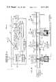
- FIG. 1is a block diagram of an implantable fluid dispensing device incorporating a fluid flow monitoring means provided by the invention
- FIG. 2is a cross-sectional diagram of the fluid dispensing conduit showing the pump, first and second valves and various electrodes;
- FIG. 3is a block diagram showing the interface between the various electrodes and the telemetry subsystem
- FIG. 4is a block diagram of one of the flow detectors shown in FIG. 3;
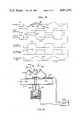
- FIG. 5is a waveform diagram showing the relationship between the first valve, pump, and second valve positions and the voltage drops measured by their corresponding second electrode pairs;
- FIG. 6is a cross-sectional diagram of the fluid dispensing conduit showing the first valve and a further embodiment of a monitoring means for determining the electrical resistance of the fluid.
- a device useful for the measurement of fluid flowfor a fluid dispensing device having a conduit for carrying fluid from a reservoir contained therein to a user's body. Positioned along the conduit is a first valve which is located proximal to the reservoir for blocking the flow of fluid through the conduit, a second valve located distal to the reservoir for blocking the flow of fluid through the conduit, and a pump located between the first and second valves which alternately increases and decreases the volume of a conduit portion between the first and second valves.
- a pumpis commonly known as a peristaltic pump.
- the pumpcan be utilized to push fluid through the conduit when the second valve is open and the first valve is closed, and then to draw fluid from the reservoir when the first valve is open and the second valve is closed.
- the device disclosedcontinuously generates signals related to the electrical resistance of the fluid across the first valve, across the conduit portion whose volume is altered by the pump, and across the second valve. The position of each valve and the pump can be accurately determined from these signals, thereby providing information necessary to calculate the flow rate through the conduit.
- a first valve 22 and a second valve 24are located in series with the conduit 18, positioned on each side of the pump 20, and controlled in synchronism with the pump 20, thereby defining a peristaltic pump.
- This synchronized operationis effected by a control electronics unit 26 so that when the pump 20 is drawing fluid from the reservoir 14 by increasing the volume of the conduit portion, the first valve 22 will by open and the second valve 24 will be closed, and when the pump is forcing fluid through the conduit to the user's body by decreasing the volume of the conduit portion, the first valve 22 will be closed and the second valve 24 will be open.
- the drug reservoir 14is filled with the appropriate fluid by the hypodermic 16.
- the pump 20is of the type which alternately reduces and increases the volume of a portion of the conduit 18.
- the control electronics unit 26When the volume of the conduit portion is being increased, the control electronics unit 26 generates the appropriate signals to close the second valve 24 and open the first valve 22.
- An increase in conduit volume caused by the pump 20draws fluid from the reservoir 14 and through the first valve 22 which is open.
- the control electronics unit 26provides the appropriate signals for causing the first valve 22 to close and the second valve 24 to open. The decrease in conduit volume then forces the fluid through the second valve 24 and the dispensing aperture 34 to the user's body.
- the drug injector 10can also operate utilizing only the first valve 22 or the second valve 24 in conjunction with the pump 20.
- the first valve 22 and the pump 20are provided, then they are synchronized so that the valve 22 is open when the pump 20 is increasing the volume of a portion of the conduit 18, and the valve is closed when the pump 20 is decreasing the volume of a portion of the conduit 18.
- the second valve 24 and the pump 20are provided, they are synchronized so that the valve 24 is closed when the pump 20 is increasing the volume of a portion of the conduit 18, and the valve 24 is open when the pump 20 is decreasing the volume of a portion of the conduit 18.
- Rthe resistivity
- the resistance of the conductoris inversely proportional to its cross-sectional area.
- This principleis utilized by the present invention to determine the flow rate through the conduit 18 by generating signals related to the fluid's resistance across the first valve 22, across the pump 20 and across the second valve 24.
- a signal related to the electrical resistance across the valve 22is a direct indication of the position of the valve 22 with respect to the conduit 18.
- volume changes in the conduit portion affected by movement of the pump piston 66can be determined by generating a signal related to the resistance of the fluid across the portion of the conduit whose cross-section is affected by the position of the piston 66, this resistance being related to the piston 66 position with respect to the conduit.
- voltage related to the electrical resistance of the fluid across the first valve 22is developed by a first set of electrodes 40, across conduit portion affected by the pump piston 66 by a second set of electrodes 42, and across the second valve 24 by a third set of electrodes 44.
- a fourth set of electrodes 46is provided in a portion of the conduit 18 which has a constant cross-sectional area.
- the fourth set of electrodescan be utilized to calculate resistivity ⁇ because the length over which fluid resistance is determined and the cross-sectional area of the conduit remain constant.
- This resistivity valuecan then be utilized for calibrating signals related to resistance from the first, second and third sets of electrodes 40, 42, and 44, respectively. This calibration is important if the fluid tends to experience resistivity changes as it is stored.
- the first valve 22includes a piston 50 located in a sleeve 52.
- the piston 50has a blade 54 connected to its top, the blade 54 being positioned in a holding structure 56 which secures both ends of the conduit 18.
- the blade 54 and holding structure 56form a gate in the conduit 18, the gate being closed when the blade 54 is in the position shown for the first valve 22.
- the bladeis held in the closed position by a spring 58.
- the lower portion of the sleeve 52'includes a solenoid switch 60' which, when activated, draws the piston 50' downwardly through the sleeve 52' into the position shown.
- the solenoid 60 of the first valveis activated to withdraw the blade 54, and the solenoid 60' of the second valve is deactivated so that the spring 58' will cause the blade 54' to move upwardly and block fluid flow through the conduit 18.
- the additional volume of the conduit portion 18 resulting from the downward movement of the piston 66will draw fluid from the reservoir 14 into the conduit 18.
- the first set of electrodes 40comprises four electrodes E1, E2, E3, and E4 that are placed across the first valve 22 for generating a signal related to the resistance of the fluid between electrodes E3 and E4 as will be explained below.
- Each of the other sets of electrodes 42, 44 and 46also comprises four electrodes.
- the first flow detector 72can be seen in FIG. 4, the other three flow detectors 74, 76 and 78 being identical to the first one 72.
- a constant current source 84is powered by the battery 36, and is chosen to provide a constant current flow through the first two electrodes E1 and E2 which are located across the first valve 22 as shown in FIG. 2. As the fluid resistance between the first electrode E1 and the second electrode E2 increases, the voltage drop across these two electrodes must also increase to maintain a constant current flow.
- the third and fourth electrodes, E3 and E4are positioned across the first valve 22 and within the conduit portion bracketed by the first and second electrodes E1 and E2.
- the third and fourth electrodes E3 and E4sense the voltage drop in the fluid between them, this voltage drop being directly related to its resistance as previously explained.
- the voltage dropis amplified by an amplifier 86.
- Four electrodesare perferred for the measurement in order to eliminate measurement uncertainties created by voltage drops between each of the current-providing electrodes E1 and E2 and the fluid in the conduit.
- the third and fourth electrodes E3 and E4are only used to sense a voltage differential and do not draw current from the fluid.
- Operation of the fluid flow monitoring devicecan be visualized in conjunction with the waveforms of FIG. 5 and the diagram of FIG. 2.
- the position of the pump piston 66 with respect to timecan be seen in waveform 90.
- the first valve 22is fully closed as shown at 94 and the second valve 24 is fully open as shown at 96.
- the piston 66is moving upwardly and decreasing the volume of the conduit 18, fluid contained in the conduit is forced outwardly through the second valve 24.
- the piston 66is moving from an up position to a down position as shown at 98
- the first valve 22is fully open as shown at 100 and the second valve 24 is fully closed as shown at 102.
- An externally located receiving meansprovides this information to a relatively simple calculation device which can precisely calculate flow rate and present that information to the user or his physician. Alternatively, th calculation could be made and the results stored in the fluid dispensing device itself, and an alarm means incorporated to alert the user when reservoir fluid is getting low.
- FIG. 6a conduit 120 having a valve 122 positioned so as to cut off fluid flow trhough the conduit is shown.
- the valve 122is identical to the valves 22 and 24 shown in FIG. 2.
- a valve 122 13is shown in FIG. 6, the monitoring device to be described could also be utilized if the valve 122 were replaced by the pump 20 shown in FIG. 2, or another type of pump such as a piezoelectric pump.
- a spirally-configured tube 124is provided, the tube 124 having a diameter that is small with respect to the diameter of the conduit 120.
- the tube 124 endsare in fluid communication with the conduit 120 at first and second apertures 126 and 128, respectively.
- the apertures 126 and 128are located on opposite sides of the conduit volume through which resistance is to be measured.
- the valve 122is located between the two apertures 126 and 128.
- An alternating voltage source 132is connected to an energizing coil 134 which is an electromagnetic coupling relationship to the tube 124 so that energy from the voltage source 132 is coupled to fluid contained within the tube 124.
- a sensing device 136includes a readout meter 138 and sensing coil 140. The sensing coil 140 is wrapped around the tube 124 and detects any alternating current flowing therethrough.
- This detected currentcan then be read on the readout meter 138 or provided to any other suitable monitoring device (not shown).
- the current flowing through the conduit 120is directly related to the cross-sectional area of the conduit 120, this cross-sectional area being a function of the position of the blade 142 with respect to the conduit.
- currentwill be at a maximum; when the blade is in the configuration shown for valve 22 in FIG. 2, current will be at a minimum.
- monitoring of the readout meter 138provides a signal that is related to the cross-sectional area of the conduit 120 amd the position of the blade 142 with respect to the conduit 120.
- an auxilliary valve 146is provided, the valve 146 configuration with respect to the tube 124 being synchronized with movement of the blade 142 by a control unit 148 so that when the blade 142 is in a blocking position with respect to the conduit 120, the valve 146 will also block fluid flow through the tube 124.
Landscapes
- Health & Medical Sciences (AREA)
- Biomedical Technology (AREA)
- Hematology (AREA)
- Vascular Medicine (AREA)
- Engineering & Computer Science (AREA)
- Anesthesiology (AREA)
- Veterinary Medicine (AREA)
- Heart & Thoracic Surgery (AREA)
- Public Health (AREA)
- Life Sciences & Earth Sciences (AREA)
- Animal Behavior & Ethology (AREA)
- General Health & Medical Sciences (AREA)
- Fluid Mechanics (AREA)
- Physics & Mathematics (AREA)
- Infusion, Injection, And Reservoir Apparatuses (AREA)
Abstract
Description
Claims (25)
Priority Applications (1)
| Application Number | Priority Date | Filing Date | Title |
|---|---|---|---|
| US06/266,835US4411651A (en) | 1981-05-26 | 1981-05-26 | Device and method useful in monitoring fluid flow in a drug injector |
Applications Claiming Priority (1)
| Application Number | Priority Date | Filing Date | Title |
|---|---|---|---|
| US06/266,835US4411651A (en) | 1981-05-26 | 1981-05-26 | Device and method useful in monitoring fluid flow in a drug injector |
Publications (1)
| Publication Number | Publication Date |
|---|---|
| US4411651Atrue US4411651A (en) | 1983-10-25 |
Family
ID=23016183
Family Applications (1)
| Application Number | Title | Priority Date | Filing Date |
|---|---|---|---|
| US06/266,835Expired - LifetimeUS4411651A (en) | 1981-05-26 | 1981-05-26 | Device and method useful in monitoring fluid flow in a drug injector |
Country Status (1)
| Country | Link |
|---|---|
| US (1) | US4411651A (en) |
Cited By (59)
| Publication number | Priority date | Publication date | Assignee | Title |
|---|---|---|---|---|
| WO1984001719A1 (en)* | 1982-11-04 | 1984-05-10 | Univ Johns Hopkins | Apparatus for detecting at least one predetermined condition and providing an informational signal in response thereto in a medication infusion system |
| US4559038A (en)* | 1984-10-19 | 1985-12-17 | Deltec Systems, Inc. | Drug delivery system |
| US4596575A (en)* | 1983-08-04 | 1986-06-24 | Omikron Scientific Ltd. | Liquid delivery system particularly useful as an implantable micropump for delivering insulin or other drugs |
| US4747832A (en)* | 1983-09-02 | 1988-05-31 | Jacques Buffet | Device for the injection of fluid, suitable for implantation |
| US4821769A (en)* | 1986-11-12 | 1989-04-18 | Cd Medical Inc. | Valve monitor and method |
| US4894342A (en)* | 1986-05-12 | 1990-01-16 | C. D. Medical, Inc. | Bioreactor system |
| US4900305A (en)* | 1988-06-27 | 1990-02-13 | Queen's University At Kingston | Ambulatory infusion pump |
| US4938742A (en)* | 1988-02-04 | 1990-07-03 | Smits Johannes G | Piezoelectric micropump with microvalves |
| US5059175A (en)* | 1990-10-09 | 1991-10-22 | University Of Utah Research Foundation | Implantable drug delivery system with piston actuation |
| US5100380A (en)* | 1984-02-08 | 1992-03-31 | Abbott Laboratories | Remotely programmable infusion system |
| US5320503A (en) | 1988-05-17 | 1994-06-14 | Patient Solutions Inc. | Infusion device with disposable elements |
| US5389078A (en)* | 1993-10-06 | 1995-02-14 | Sims Deltec, Inc. | Programmable infusion pump for administering medication to patients |
| US5584667A (en) | 1988-05-17 | 1996-12-17 | Davis; David L. | Method of providing uniform flow from an infusion device |
| US5803712A (en) | 1988-05-17 | 1998-09-08 | Patient Solutions, Inc. | Method of measuring an occlusion in an infusion device with disposable elements |
| US5810779A (en)* | 1995-12-14 | 1998-09-22 | Smiths Industries Plc | Fluid administration |
| USRE36871E (en)* | 1984-02-08 | 2000-09-12 | Abbott Laboratories | Remotely programmable infusion system |
| US6497680B1 (en) | 1999-12-17 | 2002-12-24 | Abbott Laboratories | Method for compensating for pressure differences across valves in cassette type IV pump |
| US20020198494A1 (en)* | 2001-02-23 | 2002-12-26 | Diaz Luis A. | Port assembly for an integrated medication delivery system |
| US6511473B2 (en)* | 2001-01-30 | 2003-01-28 | Biodepo, Inc. | Implantable bioartificial active secretion system |
| US6589205B1 (en)* | 1999-12-17 | 2003-07-08 | Advanced Bionica Corporation | Externally-controllable constant-flow medication delivery system |
| US20040034331A1 (en)* | 2001-02-23 | 2004-02-19 | Jason Toman | Integrated medication delivery system |
| US20050214129A1 (en)* | 2004-03-26 | 2005-09-29 | Greene Howard L | Medical infusion pump with closed loop stroke feedback system and method |
| US20060259016A1 (en)* | 2005-05-10 | 2006-11-16 | Palion Medical Corporation | Reduced size implantable pump |
| US20060259015A1 (en)* | 2005-05-10 | 2006-11-16 | Palion Medical Corporation | Implantable pump with infinitely variable resistor |
| US20070058412A1 (en)* | 2004-03-26 | 2007-03-15 | Wang David T | System and method for improved low flow medical pump delivery |
| US20070112328A1 (en)* | 2005-05-10 | 2007-05-17 | Palyon Medical Corporation | Variable flow infusion pump system |
| US20070255199A1 (en)* | 2006-05-01 | 2007-11-01 | Cardinal Health 303, Inc. | System and method for controlling administration of medical fluid |
| US20090157005A1 (en)* | 2003-04-23 | 2009-06-18 | Gonnelli Robert R | Hydraulically actuated pump for long duration medicament administration |
| US20090240232A1 (en)* | 2006-03-30 | 2009-09-24 | Vakerutas,Llc | Multi-cartridge fluid delivery device |
| US20100318025A1 (en)* | 2003-07-16 | 2010-12-16 | Michael Sasha John | Programmable medical drug delivery systems and methods for delivery of multiple fluids and concentrations |
| US8287495B2 (en) | 2009-07-30 | 2012-10-16 | Tandem Diabetes Care, Inc. | Infusion pump system with disposable cartridge having pressure venting and pressure feedback |
| US8568360B2 (en) | 2011-12-28 | 2013-10-29 | Palyon Medical (Bvi) Limited | Programmable implantable pump design |
| US8915893B2 (en) | 2005-05-10 | 2014-12-23 | Palyon Medical (Bvi) Limited | Variable flow infusion pump system |
| US9089636B2 (en) | 2004-07-02 | 2015-07-28 | Valeritas, Inc. | Methods and devices for delivering GLP-1 and uses thereof |
| US9180242B2 (en) | 2012-05-17 | 2015-11-10 | Tandem Diabetes Care, Inc. | Methods and devices for multiple fluid transfer |
| DE102016005467A1 (en)* | 2016-05-06 | 2017-11-09 | Fresenius Medical Care Deutschland Gmbh | Medical treatment device and tubing set for a medical treatment device and method for monitoring a peristaltic peristaltic pump |
| US9962486B2 (en) | 2013-03-14 | 2018-05-08 | Tandem Diabetes Care, Inc. | System and method for detecting occlusions in an infusion pump |
| US9995611B2 (en) | 2012-03-30 | 2018-06-12 | Icu Medical, Inc. | Air detection system and method for detecting air in a pump of an infusion system |
| US10022498B2 (en) | 2011-12-16 | 2018-07-17 | Icu Medical, Inc. | System for monitoring and delivering medication to a patient and method of using the same to minimize the risks associated with automated therapy |
| US10046112B2 (en) | 2013-05-24 | 2018-08-14 | Icu Medical, Inc. | Multi-sensor infusion system for detecting air or an occlusion in the infusion system |
| US10166328B2 (en) | 2013-05-29 | 2019-01-01 | Icu Medical, Inc. | Infusion system which utilizes one or more sensors and additional information to make an air determination regarding the infusion system |
| US10342917B2 (en) | 2014-02-28 | 2019-07-09 | Icu Medical, Inc. | Infusion system and method which utilizes dual wavelength optical air-in-line detection |
| US10430761B2 (en) | 2011-08-19 | 2019-10-01 | Icu Medical, Inc. | Systems and methods for a graphical interface including a graphical representation of medical data |
| US10463788B2 (en) | 2012-07-31 | 2019-11-05 | Icu Medical, Inc. | Patient care system for critical medications |
| US10578098B2 (en) | 2005-07-13 | 2020-03-03 | Baxter International Inc. | Medical fluid delivery device actuated via motive fluid |
| US10596316B2 (en) | 2013-05-29 | 2020-03-24 | Icu Medical, Inc. | Infusion system and method of use which prevents over-saturation of an analog-to-digital converter |
| US10635784B2 (en) | 2007-12-18 | 2020-04-28 | Icu Medical, Inc. | User interface improvements for medical devices |
| US10656894B2 (en) | 2017-12-27 | 2020-05-19 | Icu Medical, Inc. | Synchronized display of screen content on networked devices |
| US10850024B2 (en) | 2015-03-02 | 2020-12-01 | Icu Medical, Inc. | Infusion system, device, and method having advanced infusion features |
| US11135360B1 (en) | 2020-12-07 | 2021-10-05 | Icu Medical, Inc. | Concurrent infusion with common line auto flush |
| US11246985B2 (en) | 2016-05-13 | 2022-02-15 | Icu Medical, Inc. | Infusion pump system and method with common line auto flush |
| US11278671B2 (en) | 2019-12-04 | 2022-03-22 | Icu Medical, Inc. | Infusion pump with safety sequence keypad |
| US11324888B2 (en) | 2016-06-10 | 2022-05-10 | Icu Medical, Inc. | Acoustic flow sensor for continuous medication flow measurements and feedback control of infusion |
| US11344668B2 (en) | 2014-12-19 | 2022-05-31 | Icu Medical, Inc. | Infusion system with concurrent TPN/insulin infusion |
| US11344673B2 (en) | 2014-05-29 | 2022-05-31 | Icu Medical, Inc. | Infusion system and pump with configurable closed loop delivery rate catch-up |
| US11478578B2 (en) | 2012-06-08 | 2022-10-25 | Fresenius Medical Care Holdings, Inc. | Medical fluid cassettes and related systems and methods |
| US11883361B2 (en) | 2020-07-21 | 2024-01-30 | Icu Medical, Inc. | Fluid transfer devices and methods of use |
| US12350233B2 (en) | 2021-12-10 | 2025-07-08 | Icu Medical, Inc. | Medical fluid compounding systems with coordinated flow control |
| USD1091564S1 (en) | 2021-10-13 | 2025-09-02 | Icu Medical, Inc. | Display screen or portion thereof with graphical user interface for a medical device |
Citations (3)
| Publication number | Priority date | Publication date | Assignee | Title |
|---|---|---|---|---|
| US4137913A (en)* | 1975-02-28 | 1979-02-06 | Ivac Corporation | Fluid flow control system |
| US4207871A (en)* | 1978-06-07 | 1980-06-17 | Imed Corporation | System for controlling the flow of intravenous fluids to a patient |
| US4303376A (en)* | 1979-07-09 | 1981-12-01 | Baxter Travenol Laboratories, Inc. | Flow metering cassette and controller |
- 1981
- 1981-05-26USUS06/266,835patent/US4411651A/ennot_activeExpired - Lifetime
Patent Citations (3)
| Publication number | Priority date | Publication date | Assignee | Title |
|---|---|---|---|---|
| US4137913A (en)* | 1975-02-28 | 1979-02-06 | Ivac Corporation | Fluid flow control system |
| US4207871A (en)* | 1978-06-07 | 1980-06-17 | Imed Corporation | System for controlling the flow of intravenous fluids to a patient |
| US4303376A (en)* | 1979-07-09 | 1981-12-01 | Baxter Travenol Laboratories, Inc. | Flow metering cassette and controller |
Non-Patent Citations (1)
| Title |
|---|
| Spencer et al, IEEE Transactions of Sonic and Ultrasonics, vol. su-25, No. 3 (May, 1978).* |
Cited By (153)
| Publication number | Priority date | Publication date | Assignee | Title |
|---|---|---|---|---|
| US4619653A (en)* | 1979-04-27 | 1986-10-28 | The Johns Hopkins University | Apparatus for detecting at least one predetermined condition and providing an informational signal in response thereto in a medication infusion system |
| WO1984001719A1 (en)* | 1982-11-04 | 1984-05-10 | Univ Johns Hopkins | Apparatus for detecting at least one predetermined condition and providing an informational signal in response thereto in a medication infusion system |
| US4596575A (en)* | 1983-08-04 | 1986-06-24 | Omikron Scientific Ltd. | Liquid delivery system particularly useful as an implantable micropump for delivering insulin or other drugs |
| US4747832A (en)* | 1983-09-02 | 1988-05-31 | Jacques Buffet | Device for the injection of fluid, suitable for implantation |
| US5304126A (en)* | 1984-02-08 | 1994-04-19 | Abbott Laboratories | Infusion system having plural fluid flow lines |
| USRE36871E (en)* | 1984-02-08 | 2000-09-12 | Abbott Laboratories | Remotely programmable infusion system |
| US5464392A (en)* | 1984-02-08 | 1995-11-07 | Abbott Laboratories | Infusion system having plural fluid input ports and at least one patient output port |
| US5100380A (en)* | 1984-02-08 | 1992-03-31 | Abbott Laboratories | Remotely programmable infusion system |
| US4559038A (en)* | 1984-10-19 | 1985-12-17 | Deltec Systems, Inc. | Drug delivery system |
| US4894342A (en)* | 1986-05-12 | 1990-01-16 | C. D. Medical, Inc. | Bioreactor system |
| US4821769A (en)* | 1986-11-12 | 1989-04-18 | Cd Medical Inc. | Valve monitor and method |
| US4938742A (en)* | 1988-02-04 | 1990-07-03 | Smits Johannes G | Piezoelectric micropump with microvalves |
| US5584667A (en) | 1988-05-17 | 1996-12-17 | Davis; David L. | Method of providing uniform flow from an infusion device |
| US6312227B1 (en) | 1988-05-17 | 2001-11-06 | I-Flow Corp. | Infusion device with disposable elements |
| US6742992B2 (en) | 1988-05-17 | 2004-06-01 | I-Flow Corporation | Infusion device with disposable elements |
| US5320503A (en) | 1988-05-17 | 1994-06-14 | Patient Solutions Inc. | Infusion device with disposable elements |
| US6146109A (en) | 1988-05-17 | 2000-11-14 | Alaris Medical Systems, Inc. | Infusion device with disposable elements |
| US5803712A (en) | 1988-05-17 | 1998-09-08 | Patient Solutions, Inc. | Method of measuring an occlusion in an infusion device with disposable elements |
| AU614384B2 (en)* | 1988-06-27 | 1991-08-29 | Queen's University At Kingston | Ambulatory infusion pump |
| US4900305A (en)* | 1988-06-27 | 1990-02-13 | Queen's University At Kingston | Ambulatory infusion pump |
| US5059175A (en)* | 1990-10-09 | 1991-10-22 | University Of Utah Research Foundation | Implantable drug delivery system with piston actuation |
| US5389078A (en)* | 1993-10-06 | 1995-02-14 | Sims Deltec, Inc. | Programmable infusion pump for administering medication to patients |
| US5810779A (en)* | 1995-12-14 | 1998-09-22 | Smiths Industries Plc | Fluid administration |
| US7402154B2 (en) | 1999-12-17 | 2008-07-22 | Hospira, Inc. | Method for compensating for pressure differences across valves in cassette type IV pump |
| US20030055375A1 (en)* | 1999-12-17 | 2003-03-20 | Holst Peter A. | Method for compensating for pressure differences across valves in cassette type IV pump |
| US6589205B1 (en)* | 1999-12-17 | 2003-07-08 | Advanced Bionica Corporation | Externally-controllable constant-flow medication delivery system |
| US7407489B2 (en) | 1999-12-17 | 2008-08-05 | Hospira, Inc. | Methods for compensating for pressure differences across valves in IV pumps |
| US6497680B1 (en) | 1999-12-17 | 2002-12-24 | Abbott Laboratories | Method for compensating for pressure differences across valves in cassette type IV pump |
| US6942636B2 (en) | 1999-12-17 | 2005-09-13 | Hospira, Inc. | Method for compensating for pressure differences across valves in cassette type IV pump |
| US20050238497A1 (en)* | 1999-12-17 | 2005-10-27 | Holst Peter A | Methods for compensating for pressure differences across valves in IV pumps |
| US20050235733A1 (en)* | 1999-12-17 | 2005-10-27 | Holst Peter A | Method for compensating for pressure differences across valves in cassette type IV pump |
| US6511473B2 (en)* | 2001-01-30 | 2003-01-28 | Biodepo, Inc. | Implantable bioartificial active secretion system |
| US7048715B2 (en) | 2001-02-23 | 2006-05-23 | Stryker Instruments | Pump assembly for an integrated medication delivery system |
| US6679862B2 (en) | 2001-02-23 | 2004-01-20 | Stryker Instruments | Integrated medication delivery system |
| US6908452B2 (en) | 2001-02-23 | 2005-06-21 | Stryker Instruments | Port assembly for an integrated medication delivery system |
| US20040106902A1 (en)* | 2001-02-23 | 2004-06-03 | Diaz Luis A. | Integrated medication delivery system |
| US20040034331A1 (en)* | 2001-02-23 | 2004-02-19 | Jason Toman | Integrated medication delivery system |
| US8328786B2 (en) | 2001-02-23 | 2012-12-11 | Stryker Corporation | Method of controlling a medication delivery system with a removable label containing instructions for setting medication delivery rate overlying a second label with patient instructions |
| US7722574B2 (en) | 2001-02-23 | 2010-05-25 | Stryker Corporation | Infusion assembly that simultaneously delivers therapeutic fluid to plural body sites |
| US20060282040A1 (en)* | 2001-02-23 | 2006-12-14 | Stryker Corporation | Infusion assembly that simultaneously delivers therapeutic fluid to plural body sites |
| US7497842B2 (en) | 2001-02-23 | 2009-03-03 | Stryker Corporation | Medication delivery system comprising a combined medication reservoir, pump assembly and an actuator allowing continuous fluid communication through the pump assembly |
| US20080275425A1 (en)* | 2001-02-23 | 2008-11-06 | Stryker Corporation | Method of controlling a medication delivery system with a removable label containing instructions for setting medication delivery rate overlying a second label with patient instructions |
| US20020198494A1 (en)* | 2001-02-23 | 2002-12-26 | Diaz Luis A. | Port assembly for an integrated medication delivery system |
| US11642456B2 (en) | 2003-04-23 | 2023-05-09 | Mannkind Corporation | Hydraulically actuated pump for fluid administration |
| US20100217191A1 (en)* | 2003-04-23 | 2010-08-26 | Valeritas, Inc. | Hydraulically actuated pump for fluid administration |
| US9072828B2 (en) | 2003-04-23 | 2015-07-07 | Valeritas, Inc. | Hydraulically actuated pump for long duration medicament administration |
| US8070726B2 (en) | 2003-04-23 | 2011-12-06 | Valeritas, Inc. | Hydraulically actuated pump for long duration medicament administration |
| US20090157005A1 (en)* | 2003-04-23 | 2009-06-18 | Gonnelli Robert R | Hydraulically actuated pump for long duration medicament administration |
| US20090198185A1 (en)* | 2003-04-23 | 2009-08-06 | Gonnelli Robert R | Hydraulically actuated pump for long duration medicament administration |
| US10525194B2 (en) | 2003-04-23 | 2020-01-07 | Valeritas, Inc. | Hydraulically actuated pump for fluid administration |
| US9511187B2 (en) | 2003-04-23 | 2016-12-06 | Valeritas, Inc. | Hydraulically actuated pump for fluid administration |
| US9125983B2 (en) | 2003-04-23 | 2015-09-08 | Valeritas, Inc. | Hydraulically actuated pump for fluid administration |
| US8591498B2 (en)* | 2003-07-16 | 2013-11-26 | Michael Sasha John | Programmable medical drug delivery systems and methods for delivery of multiple fluids and concentrations |
| US20100318025A1 (en)* | 2003-07-16 | 2010-12-16 | Michael Sasha John | Programmable medical drug delivery systems and methods for delivery of multiple fluids and concentrations |
| US20070058412A1 (en)* | 2004-03-26 | 2007-03-15 | Wang David T | System and method for improved low flow medical pump delivery |
| US7905710B2 (en) | 2004-03-26 | 2011-03-15 | Hospira, Inc. | System and method for improved low flow medical pump delivery |
| US20050214129A1 (en)* | 2004-03-26 | 2005-09-29 | Greene Howard L | Medical infusion pump with closed loop stroke feedback system and method |
| US8313308B2 (en) | 2004-03-26 | 2012-11-20 | Hospira, Inc. | Medical infusion pump with closed loop stroke feedback system and method |
| US9089636B2 (en) | 2004-07-02 | 2015-07-28 | Valeritas, Inc. | Methods and devices for delivering GLP-1 and uses thereof |
| US7637892B2 (en) | 2005-05-10 | 2009-12-29 | Palyon Medical (Bvi) Limited | Variable flow infusion pump system |
| US20060259015A1 (en)* | 2005-05-10 | 2006-11-16 | Palion Medical Corporation | Implantable pump with infinitely variable resistor |
| US8591478B2 (en) | 2005-05-10 | 2013-11-26 | Palyon Medical (Bvi) Limited | Reduced size implantable pump |
| US8114055B2 (en) | 2005-05-10 | 2012-02-14 | Palyon Medical (Bvi) Limited | Implantable pump with infinitely variable resistor |
| US8177750B2 (en) | 2005-05-10 | 2012-05-15 | Palyon Medical (Bvi) Limited | Variable flow infusion pump system |
| US8211060B2 (en) | 2005-05-10 | 2012-07-03 | Palyon Medical (Bvi) Limited | Reduced size implantable pump |
| US8915893B2 (en) | 2005-05-10 | 2014-12-23 | Palyon Medical (Bvi) Limited | Variable flow infusion pump system |
| US20070112328A1 (en)* | 2005-05-10 | 2007-05-17 | Palyon Medical Corporation | Variable flow infusion pump system |
| US20100069892A1 (en)* | 2005-05-10 | 2010-03-18 | Palyon Medical (Bvi) Limited | Variable flow infusion pump system |
| US20060259016A1 (en)* | 2005-05-10 | 2006-11-16 | Palion Medical Corporation | Reduced size implantable pump |
| US11384748B2 (en) | 2005-07-13 | 2022-07-12 | Baxter International Inc. | Blood treatment system having pulsatile blood intake |
| US10578098B2 (en) | 2005-07-13 | 2020-03-03 | Baxter International Inc. | Medical fluid delivery device actuated via motive fluid |
| US10670005B2 (en) | 2005-07-13 | 2020-06-02 | Baxter International Inc. | Diaphragm pumps and pumping systems |
| US12392335B2 (en) | 2005-07-13 | 2025-08-19 | Baxter International Inc. | Medical fluid pumping system having backflow prevention |
| US10590924B2 (en) | 2005-07-13 | 2020-03-17 | Baxter International Inc. | Medical fluid pumping system including pump and machine chassis mounting regime |
| US8821443B2 (en) | 2006-03-30 | 2014-09-02 | Valeritas, Inc. | Multi-cartridge fluid delivery device |
| US12246159B2 (en) | 2006-03-30 | 2025-03-11 | Mannkind Corporation | Multi-cartridge fluid delivery device |
| US20090240232A1 (en)* | 2006-03-30 | 2009-09-24 | Vakerutas,Llc | Multi-cartridge fluid delivery device |
| US20110137287A1 (en)* | 2006-03-30 | 2011-06-09 | Valeritas, Inc. | Multi-cartridge fluid delivery device |
| US10493199B2 (en) | 2006-03-30 | 2019-12-03 | Valeritas, Inc. | Multi-cartridge fluid delivery device |
| US8361053B2 (en) | 2006-03-30 | 2013-01-29 | Valeritas, Inc. | Multi-cartridge fluid delivery device |
| US7914499B2 (en) | 2006-03-30 | 2011-03-29 | Valeritas, Inc. | Multi-cartridge fluid delivery device |
| US9687599B2 (en) | 2006-03-30 | 2017-06-27 | Valeritas, Inc. | Multi-cartridge fluid delivery device |
| US10463785B2 (en) | 2006-05-01 | 2019-11-05 | Carefusion 303, Inc. | System and method for controlling administration of medical fluid |
| CN101437558B (en)* | 2006-05-01 | 2012-02-08 | 康尔福盛303有限公司 | Systems and methods for controlling medical fluid management |
| US8211054B2 (en) | 2006-05-01 | 2012-07-03 | Carefusion 303, Inc. | System and method for controlling administration of medical fluid |
| US9095652B2 (en) | 2006-05-01 | 2015-08-04 | Carefusion 303, Inc. | System and method for controlling administration of medical fluid |
| WO2007130868A1 (en)* | 2006-05-01 | 2007-11-15 | Cardinal Health 303, Inc. | System and method for controlling administration of medical fluid |
| RU2432188C2 (en)* | 2006-05-01 | 2011-10-27 | Кардинал Хелт 303, Инк. | Drug solution introduction control system and method |
| US11577021B2 (en) | 2006-05-01 | 2023-02-14 | Carefusion 303, Inc. | System and method for controlling administration of medical fluid |
| US20070255199A1 (en)* | 2006-05-01 | 2007-11-01 | Cardinal Health 303, Inc. | System and method for controlling administration of medical fluid |
| US10635784B2 (en) | 2007-12-18 | 2020-04-28 | Icu Medical, Inc. | User interface improvements for medical devices |
| US8287495B2 (en) | 2009-07-30 | 2012-10-16 | Tandem Diabetes Care, Inc. | Infusion pump system with disposable cartridge having pressure venting and pressure feedback |
| US12144964B2 (en) | 2009-07-30 | 2024-11-19 | Tandem Diabetes Care, Inc | Infusion pump system with disposable cartridge having pressure venting and pressure feedback |
| US12042627B2 (en) | 2009-07-30 | 2024-07-23 | Tandem Diabetes Care, Inc. | Infusion pump systems and methods |
| US11135362B2 (en) | 2009-07-30 | 2021-10-05 | Tandem Diabetes Care, Inc. | Infusion pump systems and methods |
| US8758323B2 (en) | 2009-07-30 | 2014-06-24 | Tandem Diabetes Care, Inc. | Infusion pump system with disposable cartridge having pressure venting and pressure feedback |
| US8926561B2 (en) | 2009-07-30 | 2015-01-06 | Tandem Diabetes Care, Inc. | Infusion pump system with disposable cartridge having pressure venting and pressure feedback |
| US8298184B2 (en) | 2009-07-30 | 2012-10-30 | Tandem Diabetes Care, Inc. | Infusion pump system with disposable cartridge having pressure venting and pressure feedback |
| US11285263B2 (en) | 2009-07-30 | 2022-03-29 | Tandem Diabetes Care, Inc. | Infusion pump systems and methods |
| US9211377B2 (en) | 2009-07-30 | 2015-12-15 | Tandem Diabetes Care, Inc. | Infusion pump system with disposable cartridge having pressure venting and pressure feedback |
| US11599854B2 (en) | 2011-08-19 | 2023-03-07 | Icu Medical, Inc. | Systems and methods for a graphical interface including a graphical representation of medical data |
| US11004035B2 (en) | 2011-08-19 | 2021-05-11 | Icu Medical, Inc. | Systems and methods for a graphical interface including a graphical representation of medical data |
| US11972395B2 (en) | 2011-08-19 | 2024-04-30 | Icu Medical, Inc. | Systems and methods for a graphical interface including a graphical representation of medical data |
| US10430761B2 (en) | 2011-08-19 | 2019-10-01 | Icu Medical, Inc. | Systems and methods for a graphical interface including a graphical representation of medical data |
| US12346879B2 (en) | 2011-08-19 | 2025-07-01 | Icu Medical, Inc. | Systems and methods for a graphical interface including a graphical representation of medical data |
| US11376361B2 (en) | 2011-12-16 | 2022-07-05 | Icu Medical, Inc. | System for monitoring and delivering medication to a patient and method of using the same to minimize the risks associated with automated therapy |
| US10022498B2 (en) | 2011-12-16 | 2018-07-17 | Icu Medical, Inc. | System for monitoring and delivering medication to a patient and method of using the same to minimize the risks associated with automated therapy |
| US8568360B2 (en) | 2011-12-28 | 2013-10-29 | Palyon Medical (Bvi) Limited | Programmable implantable pump design |
| US8961466B2 (en) | 2011-12-28 | 2015-02-24 | Palyon Medical (Bvi) Limited | Programmable implantable pump design |
| US10578474B2 (en) | 2012-03-30 | 2020-03-03 | Icu Medical, Inc. | Air detection system and method for detecting air in a pump of an infusion system |
| US11933650B2 (en) | 2012-03-30 | 2024-03-19 | Icu Medical, Inc. | Air detection system and method for detecting air in a pump of an infusion system |
| US9995611B2 (en) | 2012-03-30 | 2018-06-12 | Icu Medical, Inc. | Air detection system and method for detecting air in a pump of an infusion system |
| US9750871B2 (en) | 2012-05-17 | 2017-09-05 | Tandem Diabetes Care, Inc. | Pump device with multiple medicament reservoirs |
| US9180242B2 (en) | 2012-05-17 | 2015-11-10 | Tandem Diabetes Care, Inc. | Methods and devices for multiple fluid transfer |
| US10258736B2 (en) | 2012-05-17 | 2019-04-16 | Tandem Diabetes Care, Inc. | Systems including vial adapter for fluid transfer |
| US11478578B2 (en) | 2012-06-08 | 2022-10-25 | Fresenius Medical Care Holdings, Inc. | Medical fluid cassettes and related systems and methods |
| US10463788B2 (en) | 2012-07-31 | 2019-11-05 | Icu Medical, Inc. | Patient care system for critical medications |
| US12280239B2 (en) | 2012-07-31 | 2025-04-22 | Icu Medical, Inc. | Patient care system for critical medications |
| US11623042B2 (en) | 2012-07-31 | 2023-04-11 | Icu Medical, Inc. | Patient care system for critical medications |
| US9962486B2 (en) | 2013-03-14 | 2018-05-08 | Tandem Diabetes Care, Inc. | System and method for detecting occlusions in an infusion pump |
| US10874793B2 (en) | 2013-05-24 | 2020-12-29 | Icu Medical, Inc. | Multi-sensor infusion system for detecting air or an occlusion in the infusion system |
| US12048831B2 (en) | 2013-05-24 | 2024-07-30 | Icu Medical, Inc. | Multi-sensor infusion system for detecting air or an occlusion in the infusion system |
| US10046112B2 (en) | 2013-05-24 | 2018-08-14 | Icu Medical, Inc. | Multi-sensor infusion system for detecting air or an occlusion in the infusion system |
| US11596737B2 (en) | 2013-05-29 | 2023-03-07 | Icu Medical, Inc. | Infusion system and method of use which prevents over-saturation of an analog-to-digital converter |
| US11433177B2 (en) | 2013-05-29 | 2022-09-06 | Icu Medical, Inc. | Infusion system which utilizes one or more sensors and additional information to make an air determination regarding the infusion system |
| US12059551B2 (en) | 2013-05-29 | 2024-08-13 | Icu Medical, Inc. | Infusion system and method of use which prevents over-saturation of an analog-to-digital converter |
| US10596316B2 (en) | 2013-05-29 | 2020-03-24 | Icu Medical, Inc. | Infusion system and method of use which prevents over-saturation of an analog-to-digital converter |
| US10166328B2 (en) | 2013-05-29 | 2019-01-01 | Icu Medical, Inc. | Infusion system which utilizes one or more sensors and additional information to make an air determination regarding the infusion system |
| US10342917B2 (en) | 2014-02-28 | 2019-07-09 | Icu Medical, Inc. | Infusion system and method which utilizes dual wavelength optical air-in-line detection |
| US12083310B2 (en) | 2014-02-28 | 2024-09-10 | Icu Medical, Inc. | Infusion system and method which utilizes dual wavelength optical air-in-line detection |
| US11344673B2 (en) | 2014-05-29 | 2022-05-31 | Icu Medical, Inc. | Infusion system and pump with configurable closed loop delivery rate catch-up |
| US11344668B2 (en) | 2014-12-19 | 2022-05-31 | Icu Medical, Inc. | Infusion system with concurrent TPN/insulin infusion |
| US10850024B2 (en) | 2015-03-02 | 2020-12-01 | Icu Medical, Inc. | Infusion system, device, and method having advanced infusion features |
| US12115337B2 (en) | 2015-03-02 | 2024-10-15 | Icu Medical, Inc. | Infusion system, device, and method having advanced infusion features |
| DE102016005467A1 (en)* | 2016-05-06 | 2017-11-09 | Fresenius Medical Care Deutschland Gmbh | Medical treatment device and tubing set for a medical treatment device and method for monitoring a peristaltic peristaltic pump |
| EP3452135B1 (en)* | 2016-05-06 | 2020-12-23 | Fresenius Medical Care Deutschland GmbH | Medical treatment device and hose set for a medical treatment device |
| US11364375B2 (en) | 2016-05-06 | 2022-06-21 | Fresenius Medical Care Deutschland Gmbh | Medical treatment device and hose set for a medical treatment device and method for monitoring a peristaltic hose pump |
| US12201811B2 (en) | 2016-05-13 | 2025-01-21 | Icu Medical, Inc. | Infusion pump system and method with common line auto flush |
| US11246985B2 (en) | 2016-05-13 | 2022-02-15 | Icu Medical, Inc. | Infusion pump system and method with common line auto flush |
| US12076531B2 (en) | 2016-06-10 | 2024-09-03 | Icu Medical, Inc. | Acoustic flow sensor for continuous medication flow measurements and feedback control of infusion |
| US11324888B2 (en) | 2016-06-10 | 2022-05-10 | Icu Medical, Inc. | Acoustic flow sensor for continuous medication flow measurements and feedback control of infusion |
| US11029911B2 (en) | 2017-12-27 | 2021-06-08 | Icu Medical, Inc. | Synchronized display of screen content on networked devices |
| US11868161B2 (en) | 2017-12-27 | 2024-01-09 | Icu Medical, Inc. | Synchronized display of screen content on networked devices |
| US12333201B2 (en) | 2017-12-27 | 2025-06-17 | Icu Medical, Inc. | Synchronized display of screen content on networked devices |
| US10656894B2 (en) | 2017-12-27 | 2020-05-19 | Icu Medical, Inc. | Synchronized display of screen content on networked devices |
| US12268843B2 (en) | 2019-12-04 | 2025-04-08 | Icu Medical, Inc. | Infusion pump with safety sequence keypad |
| US11278671B2 (en) | 2019-12-04 | 2022-03-22 | Icu Medical, Inc. | Infusion pump with safety sequence keypad |
| US11883361B2 (en) | 2020-07-21 | 2024-01-30 | Icu Medical, Inc. | Fluid transfer devices and methods of use |
| US12310921B2 (en) | 2020-07-21 | 2025-05-27 | Icu Medical, Inc. | Fluid transfer devices and methods of use |
| US11135360B1 (en) | 2020-12-07 | 2021-10-05 | Icu Medical, Inc. | Concurrent infusion with common line auto flush |
| US12390586B2 (en) | 2020-12-07 | 2025-08-19 | Icu Medical, Inc. | Concurrent infusion with common line auto flush |
| USD1091564S1 (en) | 2021-10-13 | 2025-09-02 | Icu Medical, Inc. | Display screen or portion thereof with graphical user interface for a medical device |
| US12350233B2 (en) | 2021-12-10 | 2025-07-08 | Icu Medical, Inc. | Medical fluid compounding systems with coordinated flow control |
Similar Documents
| Publication | Publication Date | Title |
|---|---|---|
| US4411651A (en) | Device and method useful in monitoring fluid flow in a drug injector | |
| CA1192464A (en) | Variable flow implantable infusion apparatus | |
| US4384578A (en) | Bio-medical flow sensor | |
| US6203523B1 (en) | Implantable drug infusion device having a flow regulator | |
| US4443218A (en) | Programmable implantable infusate pump | |
| US4105028A (en) | Positive control intravenous fluid administration | |
| KR100655524B1 (en) | Volumetric flow measuring device for intravenous set | |
| US6582393B2 (en) | Compensating drug delivery system | |
| EP1237595B1 (en) | Device for compensating for pressure differences across valves in cassette type iv pump | |
| US4820281A (en) | Drop volume measurement system | |
| US4778451A (en) | Flow control system using boyle's law | |
| US20080154187A1 (en) | Malfunction detection in infusion pumps | |
| EP1839693B1 (en) | Methods and devices for monitoring fluid of an implantable infusion pump | |
| US10391237B2 (en) | Actuator and actuation method | |
| EP0112699A2 (en) | Flow rate monitor with optical sensing chamber | |
| US4576182A (en) | Method and apparatus for measuring liquid flow | |
| US20020042596A1 (en) | Method and apparatus to sense temperature in an implantable pump | |
| CA1262848A (en) | Procedure and device for the administering of insulin or similar long-term medicaments | |
| JPH03202072A (en) | Device and method for detecting abnormality in intravascular injection | |
| EP1779881A1 (en) | Implantable pump with reservoir level detector | |
| CN101228353A (en) | Device for driving electromagnetic pumps and associated electromagnetic metering pumps | |
| EP1135179A2 (en) | Flow regulator | |
| US10300195B2 (en) | Ambulatory infusion devices and associated methods | |
| US20240017022A1 (en) | Connection of a stopper and piston in a fluid delivery device | |
| US20080077079A1 (en) | Liquid Dosing Arrangement |
Legal Events
| Date | Code | Title | Description |
|---|---|---|---|
| AS | Assignment | Owner name:PACESETTER SYSTEMS, INC., 12884 BRADLEY AVENUE, SY Free format text:ASSIGNMENT OF ASSIGNORS INTEREST.;ASSIGNOR:SCHULMAN, JOSEPH H.;REEL/FRAME:003891/0188 Effective date:19810508 | |
| STCF | Information on status: patent grant | Free format text:PATENTED CASE | |
| AS | Assignment | Owner name:PACESETTER INFUSION, LTD., 12744 SAN FERNANDO ROAD Free format text:ASSIGNMENT OF ASSIGNORS INTEREST.;ASSIGNOR:PSI INFUSION INC. (FORMERLY PACESETTER SYSTEMS, INC.);REEL/FRAME:004623/0164 Effective date:19860507 | |
| MAFP | Maintenance fee payment | Free format text:PAYMENT OF MAINTENANCE FEE, 4TH YEAR, PL 96-517 (ORIGINAL EVENT CODE: M170); ENTITY STATUS OF PATENT OWNER: LARGE ENTITY Year of fee payment:4 | |
| FEPP | Fee payment procedure | Free format text:PAYOR NUMBER ASSIGNED (ORIGINAL EVENT CODE: ASPN); ENTITY STATUS OF PATENT OWNER: LARGE ENTITY | |
| MAFP | Maintenance fee payment | Free format text:PAYMENT OF MAINTENANCE FEE, 8TH YEAR, PL 96-517 (ORIGINAL EVENT CODE: M171); ENTITY STATUS OF PATENT OWNER: LARGE ENTITY Year of fee payment:8 | |
| FEPP | Fee payment procedure | Free format text:PAYOR NUMBER ASSIGNED (ORIGINAL EVENT CODE: ASPN); ENTITY STATUS OF PATENT OWNER: LARGE ENTITY Free format text:PAYER NUMBER DE-ASSIGNED (ORIGINAL EVENT CODE: RMPN); ENTITY STATUS OF PATENT OWNER: LARGE ENTITY Free format text:PAT HLDR NO LONGER CLAIMS SMALL ENT STAT AS SMALL BUSINESS (ORIGINAL EVENT CODE: LSM2); ENTITY STATUS OF PATENT OWNER: LARGE ENTITY | |
| AS | Assignment | Owner name:MINIMED TECHNOLOGIES LIMITED Free format text:ASSIGNMENT OF ASSIGNORS INTEREST.;ASSIGNOR:PACESETTER INFUSION, LTD. DBA MINIMED TECHNOLOGIES;REEL/FRAME:006163/0118 Effective date:19920611 Owner name:SIEMENS CORPORATION, NEW YORK Free format text:MORTGAGE;ASSIGNOR:MINIMED TECHNOLOGIES LIMITED;REEL/FRAME:006163/0130 Effective date:19920611 | |
| MAFP | Maintenance fee payment | Free format text:PAYMENT OF MAINTENANCE FEE, 12TH YEAR, LARGE ENTITY (ORIGINAL EVENT CODE: M185); ENTITY STATUS OF PATENT OWNER: LARGE ENTITY Year of fee payment:12 | |
| AS | Assignment | Owner name:MINIMED INC. A DELAWARE CORP., CALIFORNIA Free format text:ASSIGNMENT-CONFIRMATORY;ASSIGNOR:MINIMED TECHNOLOGIES LIMITED A CALIFORNIA LIMITED PARTNERSHIP;REEL/FRAME:007482/0463 Effective date:19950515 | |
| AS | Assignment | Owner name:SIEMENS CORPORATION, NEW YORK Free format text:AGREEMENT;ASSIGNOR:MINIMED, INC.;REEL/FRAME:007526/0469 Effective date:19950519 Owner name:SIEMENS CORPORATION, NEW YORK Free format text:GENERAL MORTGAGE AND SECURITY AGREEMENT;ASSIGNOR:MINIMED, INC.;REEL/FRAME:007489/0137 Effective date:19930318 | |
| AS | Assignment | Owner name:ING (U.S.) CAPITAL LLC, AS COLLATERAL, NEW YORK Free format text:SECURITY INTEREST;ASSIGNOR:MINIMED INC.;REEL/FRAME:009893/0841 Effective date:19990518 | |
| AS | Assignment | Owner name:MEDTRONIC MINIMED, INC., CALIFORNIA Free format text:CHANGE OF NAME;ASSIGNOR:MINIMED INC.;REEL/FRAME:012463/0589 Effective date:20010828 |