US4411627A - Articulated light guide - Google Patents
Articulated light guideDownload PDFInfo
- Publication number
- US4411627A US4411627AUS06/343,682US34368282AUS4411627AUS 4411627 AUS4411627 AUS 4411627AUS 34368282 AUS34368282 AUS 34368282AUS 4411627 AUS4411627 AUS 4411627A
- Authority
- US
- United States
- Prior art keywords
- light guide
- light
- orientation
- screen
- guide system
- Prior art date
- Legal status (The legal status is an assumption and is not a legal conclusion. Google has not performed a legal analysis and makes no representation as to the accuracy of the status listed.)
- Expired - Fee Related
Links
- 238000006073displacement reactionMethods0.000claimsdescription2
- 230000003287optical effectEffects0.000claimsdescription2
- 230000005540biological transmissionEffects0.000abstractdescription3
- 238000004088simulationMethods0.000abstract1
- 230000000007visual effectEffects0.000description6
- 238000004891communicationMethods0.000description1
- 230000001419dependent effectEffects0.000description1
- 238000010586diagramMethods0.000description1
- 238000003384imaging methodMethods0.000description1
- 239000003562lightweight materialSubstances0.000description1
- 238000012986modificationMethods0.000description1
- 230000004048modificationEffects0.000description1
- 238000006467substitution reactionMethods0.000description1
Images


Classifications
- G—PHYSICS
- G09—EDUCATION; CRYPTOGRAPHY; DISPLAY; ADVERTISING; SEALS
- G09B—EDUCATIONAL OR DEMONSTRATION APPLIANCES; APPLIANCES FOR TEACHING, OR COMMUNICATING WITH, THE BLIND, DEAF OR MUTE; MODELS; PLANETARIA; GLOBES; MAPS; DIAGRAMS
- G09B9/00—Simulators for teaching or training purposes
- G09B9/02—Simulators for teaching or training purposes for teaching control of vehicles or other craft
- G09B9/08—Simulators for teaching or training purposes for teaching control of vehicles or other craft for teaching control of aircraft, e.g. Link trainer
- G09B9/30—Simulation of view from aircraft
- G09B9/307—Simulation of view from aircraft by helmet-mounted projector or display
Definitions
- the present inventionrelates to visual display apparatus and particularly to head coupled apparatus for providing a visual display to an observer such as seen from a moving perspective point. More particularly, the present device relates to apparatus for sensing the orientation of the images generated by such a visual display apparatus, when they are projected on a screen, and then orienting the images with respect to a known reference.
- the present inventionrepresents an improvement in the field of visual display apparatus, in that it provides a means for sensing the orientation of the image directly on the image screen and then orienting the image in accordance with a predetermined reference, such as the horizon.
- the inventionis to be used in conjunction with a computer image generating means which utilizes a plurality of scan lines to form the image at the image screen.
- the computer generated imageis communicated to a helmet mounted projector which positions the image on an image screen.
- Imbedded in the screenis an array of photodiodes which sense the orientation of the scan lines and output electrical signals which are used to determine the degree of correction or compensation required to align the scan lines with the chosen reference.
- An image rotating meansis utilized to accomplish the desired correction.
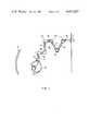
- FIG. 1shows an articulated light guide for communication with a helmet mounted projector in conjunction with an imaging screen
- FIG. 2is an interior view of the joint elements
- FIG. 3is a block diagram of the system components.
- FIG. 1discloses the present invention in an embodiment wherein a computer image generator serves as light source 11 which generates an image utilizing a plurality of scan lines.
- An articulated light guide 12is employed as a communicating means for conveying said image to a projector apparatus 13 mounted atop a helmet 15 to be worn by an observer 16.
- Projector apparatus 13is a wide angle lens suitably selected to project said light data across the desired field of view onto a retroreflective screen 21.
- Articulated light guide 12employs a plurality of link elements 25 through 31, which are constructed of a light weight material such as plastic, each link element being connected to an adjacent element by a joint element 33.
- Each joint element 33forms a fixed predetermined angle, the light data being deflected through this angle by an internal mirror 39.
- mirror 39will be set at a 45° angle to the incident light data.
- Mirror 39can be adjusted by three screws 42, 43, and 44.
- Link element 28is fixedly coupled to joint element 33, while link element 29 is rotatably coupled to joint element 33.
- a bearing element 41is attached to link element 29 so as to allow the rotation of link element 29 within joint element 33.
- Transmission of light data through communicating means 12distorts the data such that a visual image appearing on screen 21 will not be properly oriented.
- each scan line output by light source 11is monitored by a sensor apparatus 50 utilizing a plurality of photodetectors 52 embedded in screen 21.
- Sensor apparatus 50determines the orientation of each scan line relevant to the horizontal plane.
- UDT 131A non-contact optical displacement systemmanufactured by United Detector Technology, Inc.
- the orientation information thus providedis utilized as an input to a servo control electronics circuit 54 which directs a servo motor 56 to rotate a dove prism 47 located at the output of light source 11. Prism 47 is rotated to orient the scan lines provided by light source 11 in the horizontal direction at image surface 21.
- This novel combinationprovides a closed loop feedback system dependent on the actual orientation of the scan lines as output by the light guide, rather than on positional estimates as heretofore used.
- lightweight articulated light guide 12provides a minimally restrictive transmission path for light data from light source 11 through prism 47 to projector apparatus 13, which broadcasts the light data onto retroreflective screen 21 where sensor apparatus 50 determines the orientation of said data with respect to the horizon. This orientation information is used to rotate prism 47 to align the light data in the preferred direction.
Landscapes
- Engineering & Computer Science (AREA)
- Theoretical Computer Science (AREA)
- Aviation & Aerospace Engineering (AREA)
- Business, Economics & Management (AREA)
- Physics & Mathematics (AREA)
- Educational Administration (AREA)
- Educational Technology (AREA)
- General Physics & Mathematics (AREA)
- Length Measuring Devices By Optical Means (AREA)
Abstract
Description
Claims (6)
Priority Applications (1)
| Application Number | Priority Date | Filing Date | Title |
|---|---|---|---|
| US06/343,682US4411627A (en) | 1982-01-28 | 1982-01-28 | Articulated light guide |
Applications Claiming Priority (1)
| Application Number | Priority Date | Filing Date | Title |
|---|---|---|---|
| US06/343,682US4411627A (en) | 1982-01-28 | 1982-01-28 | Articulated light guide |
Publications (1)
| Publication Number | Publication Date |
|---|---|
| US4411627Atrue US4411627A (en) | 1983-10-25 |
Family
ID=23347156
Family Applications (1)
| Application Number | Title | Priority Date | Filing Date |
|---|---|---|---|
| US06/343,682Expired - Fee RelatedUS4411627A (en) | 1982-01-28 | 1982-01-28 | Articulated light guide |
Country Status (1)
| Country | Link |
|---|---|
| US (1) | US4411627A (en) |
Cited By (4)
| Publication number | Priority date | Publication date | Assignee | Title |
|---|---|---|---|---|
| US6057810A (en)* | 1996-06-20 | 2000-05-02 | Immersive Technologies, Inc. | Method and apparatus for orientation sensing |
| US20040114221A1 (en)* | 2002-12-17 | 2004-06-17 | Piontkowski Paul K. | Stereo microscope |
| US20040113029A1 (en)* | 2002-12-17 | 2004-06-17 | Piontkowski Paul K. | Head manipulable binocular microscope support |
| WO2006013356A1 (en)* | 2004-08-03 | 2006-02-09 | Iain Chapman | Articulated image guide apparatus |
Citations (9)
| Publication number | Priority date | Publication date | Assignee | Title |
|---|---|---|---|---|
| US3205303A (en)* | 1961-03-27 | 1965-09-07 | Philco Corp | Remotely controlled remote viewing system |
| US3283418A (en)* | 1964-03-23 | 1966-11-08 | Miles Electronics Ltd | Vehicle trainers |
| US3367046A (en)* | 1965-12-22 | 1968-02-06 | Gen Precision Inc | Visual simulator |
| US3459465A (en)* | 1967-07-03 | 1969-08-05 | Bell Aerospace Corp | Optical system for visual flight simulation |
| US3811204A (en)* | 1973-03-22 | 1974-05-21 | Us Navy | Programmable laser marksmanship trainer |
| US3892051A (en)* | 1973-10-31 | 1975-07-01 | Gen Electric | Simulated collimation of computer generated images |
| US4048653A (en)* | 1974-10-16 | 1977-09-13 | Redifon Limited | Visual display apparatus |
| US4100571A (en)* | 1977-02-03 | 1978-07-11 | The United States Of America As Represented By The Secretary Of The Navy | 360° Non-programmed visual system |
| US4103435A (en)* | 1976-10-08 | 1978-08-01 | The United States Of America As Represented By The Secretary Of The Navy | Head trackable wide angle visual system |
- 1982
- 1982-01-28USUS06/343,682patent/US4411627A/ennot_activeExpired - Fee Related
Patent Citations (9)
| Publication number | Priority date | Publication date | Assignee | Title |
|---|---|---|---|---|
| US3205303A (en)* | 1961-03-27 | 1965-09-07 | Philco Corp | Remotely controlled remote viewing system |
| US3283418A (en)* | 1964-03-23 | 1966-11-08 | Miles Electronics Ltd | Vehicle trainers |
| US3367046A (en)* | 1965-12-22 | 1968-02-06 | Gen Precision Inc | Visual simulator |
| US3459465A (en)* | 1967-07-03 | 1969-08-05 | Bell Aerospace Corp | Optical system for visual flight simulation |
| US3811204A (en)* | 1973-03-22 | 1974-05-21 | Us Navy | Programmable laser marksmanship trainer |
| US3892051A (en)* | 1973-10-31 | 1975-07-01 | Gen Electric | Simulated collimation of computer generated images |
| US4048653A (en)* | 1974-10-16 | 1977-09-13 | Redifon Limited | Visual display apparatus |
| US4103435A (en)* | 1976-10-08 | 1978-08-01 | The United States Of America As Represented By The Secretary Of The Navy | Head trackable wide angle visual system |
| US4100571A (en)* | 1977-02-03 | 1978-07-11 | The United States Of America As Represented By The Secretary Of The Navy | 360° Non-programmed visual system |
Cited By (6)
| Publication number | Priority date | Publication date | Assignee | Title |
|---|---|---|---|---|
| US6057810A (en)* | 1996-06-20 | 2000-05-02 | Immersive Technologies, Inc. | Method and apparatus for orientation sensing |
| US20040114221A1 (en)* | 2002-12-17 | 2004-06-17 | Piontkowski Paul K. | Stereo microscope |
| US20040113029A1 (en)* | 2002-12-17 | 2004-06-17 | Piontkowski Paul K. | Head manipulable binocular microscope support |
| US7207531B2 (en)* | 2002-12-17 | 2007-04-24 | Piontkowski Paul K | Head manipulable binocular microscope support |
| US7253949B2 (en) | 2002-12-17 | 2007-08-07 | Piontkowski Paul K | Stereo microscope |
| WO2006013356A1 (en)* | 2004-08-03 | 2006-02-09 | Iain Chapman | Articulated image guide apparatus |
Similar Documents
| Publication | Publication Date | Title |
|---|---|---|
| EP0874218B1 (en) | Surveying instrument | |
| US5668629A (en) | Remote tracking system particulary for moving picture cameras and method | |
| US4527055A (en) | Apparatus for selectively viewing either of two scenes of interest | |
| US4488173A (en) | Method of sensing the position and orientation of elements in space | |
| US4304487A (en) | Range finder for still or moving picture cameras | |
| US4647761A (en) | Airborne system for the electrooptical detection, location and omnidirectional tracking of a target | |
| US20010017651A1 (en) | Moving imager camera for track and range capture | |
| AU679599B2 (en) | Integrated photographing apparatus mounted on aircraft | |
| US3989947A (en) | Telescope cluster | |
| CA2084201A1 (en) | Remote tracking system particularly for moving picture cameras and method | |
| JPH08190161A (en) | Satellite focal plane array imager | |
| US2945414A (en) | Optical scanning device | |
| US3622797A (en) | Radiation sensitive automatic focus system | |
| US3952151A (en) | Method and apparatus for stabilized reproduction of remotely-sensed images | |
| US4588382A (en) | Wide angle area-of-interest visual image projection system | |
| GB1591947A (en) | Apparatus for viewing a target and directing a guide beam thereat | |
| US3591250A (en) | Mechanical image motion stabilizer with rotation rate comparison system | |
| US4411627A (en) | Articulated light guide | |
| EP0235944B1 (en) | Optical aiming device | |
| US3057953A (en) | Target tracking system | |
| US5986810A (en) | Imaging system | |
| US4183640A (en) | Automatic focus adjusting device | |
| US7146105B1 (en) | MEMS-based optical wireless communication system | |
| US5220456A (en) | Mirror positioning assembly for stabilizing the line-of-sight in a two-axis line-of-sight pointing system | |
| US5221985A (en) | Optical communication system |
Legal Events
| Date | Code | Title | Description |
|---|---|---|---|
| AS | Assignment | Owner name:UNITED STATES OF AMERICA, AS REPRESENTED BY THE SE Free format text:ASSIGNMENT OF ASSIGNORS INTEREST.;ASSIGNORS:BREGLIA, DENIS R.;OHAREK, FRANK J.;GRIMMER, PAUL D.;REEL/FRAME:003983/0786 Effective date:19820125 | |
| FEPP | Fee payment procedure | Free format text:MAINTENANCE FEE REMINDER MAILED (ORIGINAL EVENT CODE: REM.); ENTITY STATUS OF PATENT OWNER: LARGE ENTITY | |
| FEPP | Fee payment procedure | Free format text:MAINTENANCE FEE REMINDER MAILED (ORIGINAL EVENT CODE: REM.); ENTITY STATUS OF PATENT OWNER: LARGE ENTITY | |
| FEPP | Fee payment procedure | Free format text:SURCHARGE FOR LATE PAYMENT, PL 96-517 (ORIGINAL EVENT CODE: M176); ENTITY STATUS OF PATENT OWNER: LARGE ENTITY | |
| MAFP | Maintenance fee payment | Free format text:PAYMENT OF MAINTENANCE FEE, 4TH YEAR, PL 96-517 (ORIGINAL EVENT CODE: M170); ENTITY STATUS OF PATENT OWNER: LARGE ENTITY Year of fee payment:4 | |
| FEPP | Fee payment procedure | Free format text:MAINTENANCE FEE REMINDER MAILED (ORIGINAL EVENT CODE: REM.); ENTITY STATUS OF PATENT OWNER: LARGE ENTITY | |
| LAPS | Lapse for failure to pay maintenance fees | ||
| FP | Lapsed due to failure to pay maintenance fee | Effective date:19911027 | |
| STCH | Information on status: patent discontinuation | Free format text:PATENT EXPIRED DUE TO NONPAYMENT OF MAINTENANCE FEES UNDER 37 CFR 1.362 |