US4411624A - Dental implant - Google Patents
Dental implantDownload PDFInfo
- Publication number
- US4411624A US4411624AUS06/309,513US30951381AUS4411624AUS 4411624 AUS4411624 AUS 4411624AUS 30951381 AUS30951381 AUS 30951381AUS 4411624 AUS4411624 AUS 4411624A
- Authority
- US
- United States
- Prior art keywords
- dental
- root
- biologically active
- implant
- jaw bone
- Prior art date
- Legal status (The legal status is an assumption and is not a legal conclusion. Google has not performed a legal analysis and makes no representation as to the accuracy of the status listed.)
- Expired - Fee Related
Links
- 239000004053dental implantSubstances0.000titleclaimsabstractdescription50
- 210000004746tooth rootAnatomy0.000claimsabstractdescription73
- 230000003247decreasing effectEffects0.000claimsabstractdescription6
- 239000011521glassSubstances0.000claimsdescription15
- 239000006112glass ceramic compositionSubstances0.000claims1
- 239000011149active materialSubstances0.000abstractdescription22
- 239000007943implantSubstances0.000description12
- 210000000988bone and boneAnatomy0.000description10
- 239000002241glass-ceramicSubstances0.000description10
- 229910052751metalInorganic materials0.000description9
- 239000002184metalSubstances0.000description9
- 238000002513implantationMethods0.000description7
- 238000010008shearingMethods0.000description7
- 238000004364calculation methodMethods0.000description5
- 210000000981epitheliumAnatomy0.000description4
- 239000000463materialSubstances0.000description4
- BASFCYQUMIYNBI-UHFFFAOYSA-NplatinumChemical compound[Pt]BASFCYQUMIYNBI-UHFFFAOYSA-N0.000description4
- 239000000126substanceSubstances0.000description4
- 230000007423decreaseEffects0.000description3
- 230000000694effectsEffects0.000description3
- 238000000034methodMethods0.000description3
- 229910045601alloyInorganic materials0.000description2
- 239000000956alloySubstances0.000description2
- 238000010276constructionMethods0.000description2
- 238000005553drillingMethods0.000description2
- 238000012986modificationMethods0.000description2
- 230000004048modificationEffects0.000description2
- 229910052697platinumInorganic materials0.000description2
- 239000011347resinSubstances0.000description2
- 229920005989resinPolymers0.000description2
- RTAQQCXQSZGOHL-UHFFFAOYSA-NTitaniumChemical compound[Ti]RTAQQCXQSZGOHL-UHFFFAOYSA-N0.000description1
- WAIPAZQMEIHHTJ-UHFFFAOYSA-N[Cr].[Co]Chemical class[Cr].[Co]WAIPAZQMEIHHTJ-UHFFFAOYSA-N0.000description1
- PNEYBMLMFCGWSK-UHFFFAOYSA-Naluminium oxideInorganic materials[O-2].[O-2].[O-2].[Al+3].[Al+3]PNEYBMLMFCGWSK-UHFFFAOYSA-N0.000description1
- 230000015572biosynthetic processEffects0.000description1
- 239000007767bonding agentSubstances0.000description1
- 239000000919ceramicSubstances0.000description1
- PRQRQKBNBXPISG-UHFFFAOYSA-Nchromium cobalt molybdenum nickelChemical compound[Cr].[Co].[Ni].[Mo]PRQRQKBNBXPISG-UHFFFAOYSA-N0.000description1
- 238000004519manufacturing processMethods0.000description1
- 229910001092metal group alloyInorganic materials0.000description1
- 150000002739metalsChemical class0.000description1
- 239000000203mixtureSubstances0.000description1
- -1platinumChemical class0.000description1
- 229910052703rhodiumInorganic materials0.000description1
- 239000010948rhodiumSubstances0.000description1
- 239000010935stainless steelSubstances0.000description1
- 229910001220stainless steelInorganic materials0.000description1
- 239000010936titaniumSubstances0.000description1
- 229910052719titaniumInorganic materials0.000description1
Images

Classifications
- A—HUMAN NECESSITIES
- A61—MEDICAL OR VETERINARY SCIENCE; HYGIENE
- A61C—DENTISTRY; APPARATUS OR METHODS FOR ORAL OR DENTAL HYGIENE
- A61C8/00—Means to be fixed to the jaw-bone for consolidating natural teeth or for fixing dental prostheses thereon; Dental implants; Implanting tools
- A61C8/0018—Means to be fixed to the jaw-bone for consolidating natural teeth or for fixing dental prostheses thereon; Dental implants; Implanting tools characterised by the shape
- A—HUMAN NECESSITIES
- A61—MEDICAL OR VETERINARY SCIENCE; HYGIENE
- A61C—DENTISTRY; APPARATUS OR METHODS FOR ORAL OR DENTAL HYGIENE
- A61C8/00—Means to be fixed to the jaw-bone for consolidating natural teeth or for fixing dental prostheses thereon; Dental implants; Implanting tools
- A61C8/0012—Means to be fixed to the jaw-bone for consolidating natural teeth or for fixing dental prostheses thereon; Dental implants; Implanting tools characterised by the material or composition, e.g. ceramics, surface layer, metal alloy
- A61C8/0013—Means to be fixed to the jaw-bone for consolidating natural teeth or for fixing dental prostheses thereon; Dental implants; Implanting tools characterised by the material or composition, e.g. ceramics, surface layer, metal alloy with a surface layer, coating
Definitions
- the present inventionrelates to a dental implant, and more particularly to an implant of the type which comprises a dental root to be embedded in a jaw bone alone or in combination with a dental crown or a dental crown support.
- the basic material used for making the dental implantis metal or ceramics which is inactive in a living body. They are so designed as to be mechanically supported by the jaw bone. In other words, almost all of the known dental implants rely on a mechanical bonding force between the implant and the jaw bone. For this reason, the known dental implants are complicated in shape and are difficult to manufacture. In addition, they are apt to slip out due to the resorption of the jaw bone caused by the partial concentration of stress on a part thereof.
- a very useful dental implantcan be obtained by forming its dental root part with a biologically active material such as biologically active glass or glass-ceramics (cf. U.S. Pat. Nos. 4,159,358 and 4,234,972).
- biologically active materialis able chemically to combine with bone. Therefore, if a dental implant is made of such biologically active material, then it is possible rigidly to fix the implant to the jaw bone without the need for mechanical bonding, and it enables simplification of the shape of the implant to a great extent.
- the bonding strength between biologically active material and bonehas a certain limit.
- the dental implant using a biologically active materialcan be designed to have a very simple form, there remains the possibility that the chemical bond between the implant and the bone may be broken and the implant may come out when a large stress is applied thereto by biting, for example, and the stress is concentrated on a limited portion of the dental implant.
- One aspect of our inventionresides in the fact that such dental implant has a dental root so designed as to bond with the jaw bone with a possible maximum stability in view of dynamics.
- the dental implant according to the inventionis, therefore, characterized in its improved form of the dental root to be embedded in the jaw bone.
- the dental implantis composed of the dental root alone or a combination of the dental root and a dental crown or a dental crown support part.
- the dental rootis made of a biologically active material at least at a major portion if its surface to be positioned in contact with the jaw bone.
- the external appearance of the dental rootis rotationally symmetrical and the diameter thereof is constant or decreased monotonously from the collum dentis, that is, one end of the dental root to the root end portion, that is, the other end of the dental root. At the root end portion, the dental root is smoothly closed.
- FIG. 1is a schematic sectional view of a denture as a computation model
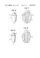
- FIG. 2is a schematic perspective view of a dental root
- FIGS. 3 and 4are side elevations of dental roots having different shapes
- FIG. 5is a graph showing the relation between the form of dental root and the maximum value of shearing stress
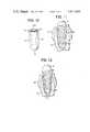
- FIG. 6is a perspective view of a first embodiment of the invention.
- FIG. 7is a cross-sectional view thereof with the dental implant embedded in the jaw bones
- FIG. 8shows a second embodiment
- FIG. 9is a view similar to FIG. 7 but showing the second embodiment
- FIG. 10shows a third embodiment
- FIG. 11is a view of the third embodiment similar to FIG. 7;
- FIG. 12is a cross-sectional view of a fourth embodiment of the invention.
- the dynamic stability of a dental implantis determined by the resistance to the level of stress between the bonding surface of the bone and the biologically active material. Therefore, it is essential that the magnitude and distribution of the stress which may be applied onto the interface between the biologically active material and bone be thoroughly considered and that the shape of the dental implant be designed in such manner that no great stress may be applied to the area in the vicinity of the interface.
- the denturecomprises a root core 11 covered with a layer of biologically active glass 12, a metal post core 13 inserted into a recessed portion of the root core 11 and a dental crown 14 mounted on the metal post core 13.
- the biologically active glass layer 12covers the surface area of the core 11 extending from its lower root end portion 1a to its collum dentis 1b.
- the dental rootis implanted in a jaw bone 2.
- the metal post core 13is fitted into the root core 11 in the manner shown in FIG. 1.
- the dental crown 14 mounted on the metal core 13is made of resin.
- the dental rootshould have a form of a rotationally symmetrical body basically composed of a truncated cone and a semi-sphere jointed together;
- the dental rootshould have a diameter decreasing monotonously from one end thereof, namely the collum dentis 1b to the other end, namely the root end 1a;
- the root end portion 1ashould be closed smoothly, for example, forming a semi-sphere.
- the form of the side surface of the preferred dental root, excepting the root end portion,is never limited only to a cone as shown in FIG. 2. It may be, for example, cylindrical. Also, it may be in a form as shown in FIG. 3 where the changing rate of diameter increases gradually toward the root end 1a. Further, it may be a form as shown in FIG. 4 wherein the changing rate of diameter is larger at the area near the collum dentis 1b and decreases toward the root end 1a.
- the concentration of stressmay be minimized and therefore the stability of the dental root can be improved.
- the root end 1ashould be closed smoothly.
- the forms of dental root shown in FIGS. 3 and 4may be considered to be slight modifications of the basic form shown in FIG. 2. Therefore, it should be understood that the form shown in FIG. 2 represents the basic form of the dental root according to the invention.
- the internal structure of the dental rootis of no critical importance.
- the bonding strength between a root core made of metal or other material and a biologically active materialis larger than that between the biologically active material and a bone. Therefore, the thing to be considered is only the bonding strength between the bone and the biologically active material.
- the internal structure of the dental roothas no substantial effect on the dynamic stability of the implant after implantation. Even when the whole body of a dental root is composed of only biologically active material, the stability of the dental implant can be improved by designing it to have a form as described above.
- FIG. 5is a graphic illustration of the result wherein (r 1 /r 0 ) 2 is plotted on the abscissa and the maximum shearing stress, Tm on the ordinate.
- the maximum shearing stressmay be considered to be proportional to the surface area of the root end portion, that is, to (r 1 /r 0 ) 2 . Therefore, the correlation between the form of dental root and the maximum shearing force can be found by binding two points on the graph with a straight line. From the graph shown in FIG. 5 is it clearly seen that the maximum shearing stress, Tm decreases with increasing the radius of the root end portion, r 1 relative to r 0 .
- the use of such dental root having a cylindrical forminvolves some drawback.
- the dental root fitted in the boreis apt to move in the axial direction of the cylinder. Therefore, the fitting accuracy is not as precise as compared with the case of a dental root whose diameter is decreased monotonously from the collum dentis to the root end portion. For this reason, it is preferable that the value of r 1 /r 0 be less than 1.
- FIG. 6is a perspective view of a dental implant showing a first embodiment of the invention.
- a dental root part1b is the collum dentis portion of the dental root and 1a is the root end portion.
- 1cis a support part for supporting a dental crown (not shown).
- the dental root part and the support partare integrally formed as a unit entirely made of a biologically active glass or glass-ceramics.
- Biologically active glass or glass-ceramics used in the inventionis known per se. for example, there may be used those glass compositions as disclosed in U.S. Pat. Nos. 4,234,972; 3,981,736 and 4,120,730.
- Other preferred biologically active glass and glass-ceramicsare those which have been proposed by our prior invention.
- the biologically active glass and glass-ceramics previously invented by usessentially comprise:
- the dental root part 1is so designed as to decrease the radius continuously from the collum dentis portion 1b to the root end portion 1a which is smoothly closed forming a semi-sphere.
- the dental implantis implanted ina jaw bone 21 with which the dental implant is to be bonded.
- FIG. 7shows the dental implant after completing a sufficient bond between the dental implant and the jaw bone.
- the dental root part 1is implanted with its collum dentis portion 1b being embedded in the jaw bone 21 as shown in FIG. 7. In this position, the collum dentis portion 1b corresponds to the collum dentis of a natural tooth.
- the biologically active glass or glass-ceramics of the dental root part 1 at the surface area in contact with the jaw bonebegins chemically to bond with the jaw bone. Within four to eight weeks there is obtained a sufficiently large bonding strength for practical purpose.
- a dental crown 4 made of resinis mounted on the crown support part 1c and the dental crown 4 is firmly fixed to the dental root part 1 by means of a bonding agent.
- the epithelial tissue 22 on the jaw bone 21developes up to the collum dentis portion 1b so as completely to isolate the dental root part 1 from the exterior and also the closing of the epithelial tissue 22 is completed.
- FIGS. 8 and 9show a second embodiment of the invention.
- the dental root part 1is composed of a root core 11 and a layer of biologically active glass or glass-ceramics 12 applied on the core 11.
- the biologically active layer 12covers the area extending from the root end portion 1a to the collum dentis portion 1b.
- the dental root part 1has a projection 11a formed on the top of the core 11.
- the projection 11aserves also as a support member for supporting a dental crown 4.
- this structure of the second embodimenthas a further improved mechanical strength on the whole of the dental implant including the dental root part.
- the root core 11may be formed of any suitable material having an adequately high mechanical strength.
- Such materialexamples include: stainless steel, cobalt-chromium alloy, titanium and its alloys, nobel metals such as platinum, nobel metal alloys such as platinum(90%)-rhodium(10%), molybdenum-nickel-cobalt-chromium alloy and alumina.
- FIG. 9shows the second embodiment implant after implantation has been completed.
- Like reference numerals of the first embodimentrepresent the same or corresponding parts and elements.
- the second embodimenteliminates the concentration of stress on the interface between the jaw bone and the biologically active material.
- the epithelial tissue 22is finally closed completely to provide practically sufficient stability for the dental implant.
- FIGS. 10 and 11show a third embodiment of the invention wherein FIG. 10 illustrates the structure before implantation and FIG. 11 shows it after implantation.
- the root core 15has a center bore 15a for receiving a metal post-core 16.
- the center core 15ais in the form of a truncated cone.
- the root core 15is coated with a layer of biologically active glass or glass-ceramics 12 excepting the upper end surface of the core.
- the biologically active layer 12has a substantially constant thickness (about 0.2-1.0 mm).
- the annular upper end surface of the root core 15is coplanar with the annular end surface of the biologically active layer 12 so that the upper end portion constitutes the collum dentis portion of the dental root.
- the post-core 16 mentioned aboveis fitted into the center bore 15a of the root core 15 and cemented to the latter in the manner shown in FIG. 11.
- a dental crown 4is mounted on and cemented to the dental root using the post-core 16 serving as a connection member.
- the diameter of the dental rootis decreased uniformly from the collum dentis portion 1b to the root end portion 1a which is closed smoothly forming a semi-sphere. Owing to this form of the dental root, the partial concentration of stress on the dental implant can be minimized and therefore the dynamic stability thereof can be improved remarkably.
- FIG. 12shows a fourth embodiment of the invention.
- the structure of this fourth embodimentis essentially the same as those of the above three embodiments.
- This structure of the fourth embodimentalso minimizes the stress concentration on the interface area between the biologically active glass or glass-ceramics thereby providing a dental implant of higher dynamic stability.
- the difference between the fourth embodiment and the above three embodimentsis found only in the shape of the collum dentis portion of the dental root to be embedded in the jaw bone 21. As shown in FIG. 12, it often occurs that the tip end of the jaw bone in which a dental implant is to be implanted is not flat but tapered.
- the fourth embodimentis designed to accomodate the collum dentis portion to the shape of such jaw bone.
- the annular end surfaces of the root core 15' and of the biologically active layer 12'are together cut out to form an inclined roof-like end surface.
- the roof-like end portionbecomes contiguous with the tapered end portion of the jaw bone 21 as seen in FIG. 12.
- the end surface of dental crown 4'is also shaped into an internally inclined or roof-like form to match it with the end surface of the dental root.
- the dental crown 4'is connected with the dental root through a post-core 16 to complete an artificial tooth having a smooth contour as a whole.
- the end surface of the dental root and the side surface of the same dental rootform an obtuse angle ⁇ at the collum dentis portion of the biologically active layer. This obtuse angle ⁇ has the effect to lessen the danger of the epithelial tissue being damaged by the edge of the dental root. Therefore, in view of safety, this embodiment has an advantage over the above embodiments.
- the dental implant according to the inventionhas many advantages over the prior art implants.
- the most dynamically stable dental implantcan be obtained when biologically active material is used.
- the dental root partis in the form of a rotationally symmetrical body which is easy to machine with existing apparatus and tools. Therefore, the present invention makes it possible to obtain dental implants of high precision.
- the rotationally symmetrical form of the dental roothas another advantage in that a bore necessary for implantation can be drilled in the jaw bone very easily and precisely with a dental bone drilling bar perfectly matched to the form of the dental root. Therefore, very good fitting is assured at the implanting operation.
- the dental implantIn the case of a dental implant employing a biologically active material, it is required that the dental implant should be kept motionless in the implanted position at the first stage after the implanting operation. If it moves even a little at an early stage after the operation, then no strong bonding may be obtained between the biologically active material and the jaw bone.
- the dental implantsince the dental implant has a very precise form and the implanting operation can be carried out with a very precise dental drilling bar proper to the dental implant, such undesirable motion at an early stage after the operation can be prevented completely. Accurate operation and good fitting are assured by using the dental implant according to the invention. This accelerates the formation of a good and strong bond between the dental implant and jaw bone.
- the dental implant shown in FIGS. 10 and 11 as the third embodiment of the inventiondoes not have any such portion which will project over the jaw bone after the implanting operation. As there is no projecting portion, the implant can not be moved by foreign matter which otherwise strike against the dental implant. Accuracy of operation is also improved accordingly.
- the third embodimentis an example of the dental root a form in which the effect of the present invention becomes particularly remarkable.
- all or a part of the surface of the dental root part to be in contact with a jaw bonemay be roughed or made porous to increase the coefficient of friction. By doing so, the initial fixing of the implant may be further accelerated.
Landscapes
- Health & Medical Sciences (AREA)
- Epidemiology (AREA)
- Oral & Maxillofacial Surgery (AREA)
- Orthopedic Medicine & Surgery (AREA)
- Dentistry (AREA)
- Life Sciences & Earth Sciences (AREA)
- Animal Behavior & Ethology (AREA)
- General Health & Medical Sciences (AREA)
- Public Health (AREA)
- Veterinary Medicine (AREA)
- Ceramic Engineering (AREA)
- Engineering & Computer Science (AREA)
- Dental Prosthetics (AREA)
- Materials For Medical Uses (AREA)
Abstract
Description
______________________________________ r.sub.0 r.sub.1 Tm (r.sub.1 /r.sub.0).sup.2 ______________________________________ l 0.26 1.85 kg/mm.sup.2 0.07 k 0.7 0.6 kg/mm.sup.2 0.49 ______________________________________
______________________________________ SiO.sub.2 35-60 mol % B.sub.2 O.sub.3 5-15 Na.sub.2 O 10-30 CaO 5-40 TiO.sub.2 0.5-10 P.sub.2 O.sub.5 0-15 K.sub.2 O 0-20 Li.sub.2 O 0-10 MgO 0-5 Al.sub.2 O.sub.3 + ZrO.sub.2 + Nb.sub.2 O.sub.5 0-8 La.sub.2 O.sub.3 = Ta.sub.2 O.sub.5 + Y.sub.2 O.sub.3 0-8 F.sub.2 0-15 ______________________________________
Claims (1)
0.42<r/r.sub.0 <1.0;
Applications Claiming Priority (2)
| Application Number | Priority Date | Filing Date | Title |
|---|---|---|---|
| JP55-151964 | 1980-10-29 | ||
| JP55151964AJPS5775646A (en) | 1980-10-29 | 1980-10-29 | Dental implant |
Publications (1)
| Publication Number | Publication Date |
|---|---|
| US4411624Atrue US4411624A (en) | 1983-10-25 |
Family
ID=15530056
Family Applications (1)
| Application Number | Title | Priority Date | Filing Date |
|---|---|---|---|
| US06/309,513Expired - Fee RelatedUS4411624A (en) | 1980-10-29 | 1981-10-07 | Dental implant |
Country Status (4)
| Country | Link |
|---|---|
| US (1) | US4411624A (en) |
| JP (1) | JPS5775646A (en) |
| DE (1) | DE3142393A1 (en) |
| GB (1) | GB2088722B (en) |
Cited By (22)
| Publication number | Priority date | Publication date | Assignee | Title |
|---|---|---|---|---|
| US4497629A (en)* | 1982-01-07 | 1985-02-05 | Nippon Kogaku K.K. | Dental implant and method of making same |
| US4615678A (en)* | 1984-03-06 | 1986-10-07 | Moermann Werner H | Blank from which a dental implant can be machined, and a method of making the blank |
| US4713006A (en)* | 1985-04-04 | 1987-12-15 | Olympus Optical Co., Ltd. | Artificial tooth root |
| US5427526A (en)* | 1993-12-13 | 1995-06-27 | Fernandes; Americo | Dental implant and dentistry implant method |
| WO2001034056A1 (en)* | 1999-11-09 | 2001-05-17 | Beekmans Johannes Cornelis Sta | One-part dental implant |
| US6343931B1 (en)* | 1999-09-09 | 2002-02-05 | Gerald J. Regni, Jr. | Bone augmentation method and apparatus |
| US20030036036A1 (en)* | 2001-08-17 | 2003-02-20 | Porter Stephan S. | Immediate load dental implant system and method of use |
| US6733292B2 (en) | 2002-04-15 | 2004-05-11 | Park Avenue Periodontal Associates, P.C. | Universal implant |
| US8075312B2 (en) | 2005-08-30 | 2011-12-13 | Zimmer Dental, Inc. | Dental implant with improved osseointegration features |
| US8231387B2 (en) | 2008-07-02 | 2012-07-31 | Zimmer, Inc. | Porous implant with non-porous threads |
| US20120225407A1 (en)* | 2010-07-13 | 2012-09-06 | Chun-Leon Chen | Restorable zirconium dioxide-based one piece dental implant |
| US8353702B1 (en) | 2012-01-12 | 2013-01-15 | Adaptall Manufacturing Inc. | Dental implant system |
| US8562346B2 (en) | 2005-08-30 | 2013-10-22 | Zimmer Dental, Inc. | Dental implant for a jaw with reduced bone volume and improved osseointegration features |
| US8562348B2 (en) | 2008-07-02 | 2013-10-22 | Zimmer Dental, Inc. | Modular implant with secured porous portion |
| US8602782B2 (en) | 2009-11-24 | 2013-12-10 | Zimmer Dental, Inc. | Porous implant device with improved core |
| US8814567B2 (en) | 2005-05-26 | 2014-08-26 | Zimmer Dental, Inc. | Dental implant prosthetic device with improved osseointegration and esthetic features |
| US8851891B2 (en) | 2008-11-06 | 2014-10-07 | Zimmer Dental, Inc. | Expandable bone implant |
| US8899982B2 (en) | 2008-07-02 | 2014-12-02 | Zimmer Dental, Inc. | Implant with structure for securing a porous portion |
| US9095396B2 (en) | 2008-07-02 | 2015-08-04 | Zimmer Dental, Inc. | Porous implant with non-porous threads |
| US9149345B2 (en) | 2007-08-30 | 2015-10-06 | Zimmer Dental, Inc. | Multiple root implant |
| US9707058B2 (en) | 2009-07-10 | 2017-07-18 | Zimmer Dental, Inc. | Patient-specific implants with improved osseointegration |
| US10188489B2 (en) | 2014-04-17 | 2019-01-29 | Star Generation Limited Taiwan Branch | Sinus implant |
Families Citing this family (10)
| Publication number | Priority date | Publication date | Assignee | Title |
|---|---|---|---|---|
| DE3434309A1 (en)* | 1984-09-19 | 1986-03-27 | S + G Implants GmbH, 2400 Lübeck | IMPLANT AS REPLACEMENT FOR AN EXTRACTED TOOTH |
| JPS6188024U (en)* | 1984-11-01 | 1986-06-09 | ||
| JPS62106761A (en)* | 1985-11-01 | 1987-05-18 | 旭光学工業株式会社 | dental treatment stand |
| JPH01198542A (en)* | 1988-02-01 | 1989-08-10 | Takeshi Yukimori | Instrument for forming spike and drilled hole for denture |
| JPH0235159U (en)* | 1988-08-31 | 1990-03-07 | ||
| WO1991003213A1 (en)* | 1989-08-30 | 1991-03-21 | Tdk Corporation | Artificial dental root |
| JPH03105864U (en)* | 1990-02-16 | 1991-11-01 | ||
| JP2605165B2 (en)* | 1990-06-13 | 1997-04-30 | 分吉 東 | Artificial root |
| US7850452B2 (en) | 2005-04-27 | 2010-12-14 | Biomet 3I, Llc | Pre-stressed implant component and assembly |
| DE102006036039A1 (en)* | 2006-08-02 | 2008-02-07 | Forschungszentrum Jülich GmbH | Porous outer layer implants and methods of making same |
Citations (6)
| Publication number | Priority date | Publication date | Assignee | Title |
|---|---|---|---|---|
| US3922155A (en)* | 1973-05-23 | 1975-11-25 | Leitz Ernst Gmbh | Process of making biocompatible glass ceramic |
| DE2824214A1 (en)* | 1978-06-02 | 1979-12-06 | Riess Guido Dr | Plastics moulding for connecting dental crown with tooth root - is made of polysulphone, polycarbonate, PMMA or polyester, for low water absorption |
| US4195409A (en)* | 1978-02-13 | 1980-04-01 | Child Laboratories Inc. | Dental implant |
| US4199864A (en)* | 1975-12-22 | 1980-04-29 | Arthur Ashman | Endosseous plastic implant method |
| DE2928007A1 (en)* | 1979-07-11 | 1981-01-15 | Riess Guido Dr | BONE IMPLANT BODY FOR PROSTHESES AND BONE CONNECTORS AND METHOD FOR THE PRODUCTION THEREOF |
| US4259072A (en)* | 1977-04-04 | 1981-03-31 | Kyoto Ceramic Co., Ltd. | Ceramic endosseous implant |
Family Cites Families (4)
| Publication number | Priority date | Publication date | Assignee | Title |
|---|---|---|---|---|
| DE583421C (en)* | 1933-09-02 | Eugen Brill Dr | Tooth root prosthesis made of fired ceramic material in the shape of a natural tooth root | |
| DE2111325C3 (en)* | 1970-03-19 | 1974-05-02 | Vitredent Corp | Dental implant |
| US4159358A (en)* | 1977-05-19 | 1979-06-26 | Board Of Regents, State Of Florida | Method of bonding a bioglass to metal |
| US4234972A (en)* | 1978-06-21 | 1980-11-25 | Board Of Regents, State Of Florida | Bioglass coated metal substrate |
- 1980
- 1980-10-29JPJP55151964Apatent/JPS5775646A/enactiveGranted
- 1981
- 1981-10-07USUS06/309,513patent/US4411624A/ennot_activeExpired - Fee Related
- 1981-10-26DEDE19813142393patent/DE3142393A1/ennot_activeCeased
- 1981-10-27GBGB8132347Apatent/GB2088722B/ennot_activeExpired
Patent Citations (6)
| Publication number | Priority date | Publication date | Assignee | Title |
|---|---|---|---|---|
| US3922155A (en)* | 1973-05-23 | 1975-11-25 | Leitz Ernst Gmbh | Process of making biocompatible glass ceramic |
| US4199864A (en)* | 1975-12-22 | 1980-04-29 | Arthur Ashman | Endosseous plastic implant method |
| US4259072A (en)* | 1977-04-04 | 1981-03-31 | Kyoto Ceramic Co., Ltd. | Ceramic endosseous implant |
| US4195409A (en)* | 1978-02-13 | 1980-04-01 | Child Laboratories Inc. | Dental implant |
| DE2824214A1 (en)* | 1978-06-02 | 1979-12-06 | Riess Guido Dr | Plastics moulding for connecting dental crown with tooth root - is made of polysulphone, polycarbonate, PMMA or polyester, for low water absorption |
| DE2928007A1 (en)* | 1979-07-11 | 1981-01-15 | Riess Guido Dr | BONE IMPLANT BODY FOR PROSTHESES AND BONE CONNECTORS AND METHOD FOR THE PRODUCTION THEREOF |
Cited By (31)
| Publication number | Priority date | Publication date | Assignee | Title |
|---|---|---|---|---|
| US4497629A (en)* | 1982-01-07 | 1985-02-05 | Nippon Kogaku K.K. | Dental implant and method of making same |
| US4615678A (en)* | 1984-03-06 | 1986-10-07 | Moermann Werner H | Blank from which a dental implant can be machined, and a method of making the blank |
| US4713006A (en)* | 1985-04-04 | 1987-12-15 | Olympus Optical Co., Ltd. | Artificial tooth root |
| US5427526A (en)* | 1993-12-13 | 1995-06-27 | Fernandes; Americo | Dental implant and dentistry implant method |
| US6343931B1 (en)* | 1999-09-09 | 2002-02-05 | Gerald J. Regni, Jr. | Bone augmentation method and apparatus |
| WO2001034056A1 (en)* | 1999-11-09 | 2001-05-17 | Beekmans Johannes Cornelis Sta | One-part dental implant |
| US20030036036A1 (en)* | 2001-08-17 | 2003-02-20 | Porter Stephan S. | Immediate load dental implant system and method of use |
| US6887077B2 (en) | 2001-08-17 | 2005-05-03 | Implant Innovations, Inc. | Immediate load dental implant system and method of use |
| US6733292B2 (en) | 2002-04-15 | 2004-05-11 | Park Avenue Periodontal Associates, P.C. | Universal implant |
| US8814567B2 (en) | 2005-05-26 | 2014-08-26 | Zimmer Dental, Inc. | Dental implant prosthetic device with improved osseointegration and esthetic features |
| US8075312B2 (en) | 2005-08-30 | 2011-12-13 | Zimmer Dental, Inc. | Dental implant with improved osseointegration features |
| US10070945B2 (en) | 2005-08-30 | 2018-09-11 | Zimmer Dental, Inc. | Dental implant for a jaw with reduced bone volume and improved osseointegration features |
| US8899981B2 (en) | 2005-08-30 | 2014-12-02 | Zimmer Dental, Inc. | Dental implant for a jaw with reduced bone volume and improved osseointegration features |
| US8562346B2 (en) | 2005-08-30 | 2013-10-22 | Zimmer Dental, Inc. | Dental implant for a jaw with reduced bone volume and improved osseointegration features |
| US9149345B2 (en) | 2007-08-30 | 2015-10-06 | Zimmer Dental, Inc. | Multiple root implant |
| US8562348B2 (en) | 2008-07-02 | 2013-10-22 | Zimmer Dental, Inc. | Modular implant with secured porous portion |
| US9095396B2 (en) | 2008-07-02 | 2015-08-04 | Zimmer Dental, Inc. | Porous implant with non-porous threads |
| US8231387B2 (en) | 2008-07-02 | 2012-07-31 | Zimmer, Inc. | Porous implant with non-porous threads |
| US9066771B2 (en) | 2008-07-02 | 2015-06-30 | Zimmer Dental, Inc. | Modular implant with secured porous portion |
| US8899982B2 (en) | 2008-07-02 | 2014-12-02 | Zimmer Dental, Inc. | Implant with structure for securing a porous portion |
| US9744007B2 (en) | 2008-11-06 | 2017-08-29 | Zimmer Dental, Inc. | Expandable bone implant |
| US8851891B2 (en) | 2008-11-06 | 2014-10-07 | Zimmer Dental, Inc. | Expandable bone implant |
| US9707058B2 (en) | 2009-07-10 | 2017-07-18 | Zimmer Dental, Inc. | Patient-specific implants with improved osseointegration |
| US8602782B2 (en) | 2009-11-24 | 2013-12-10 | Zimmer Dental, Inc. | Porous implant device with improved core |
| US9439738B2 (en) | 2009-11-24 | 2016-09-13 | Zimmer Dental, Inc. | Porous implant device with improved core |
| US9901424B2 (en) | 2009-11-24 | 2018-02-27 | Zimmer Dental, Inc. | Porous implant device with improved core |
| US10687919B2 (en) | 2009-11-24 | 2020-06-23 | Zimmer Dental, Inc. | Porous implant device with improved core |
| US8986007B2 (en)* | 2010-07-13 | 2015-03-24 | Star Generation Limited | Restorable zirconium dioxide-based one piece dental implant |
| US20120225407A1 (en)* | 2010-07-13 | 2012-09-06 | Chun-Leon Chen | Restorable zirconium dioxide-based one piece dental implant |
| US8353702B1 (en) | 2012-01-12 | 2013-01-15 | Adaptall Manufacturing Inc. | Dental implant system |
| US10188489B2 (en) | 2014-04-17 | 2019-01-29 | Star Generation Limited Taiwan Branch | Sinus implant |
Also Published As
| Publication number | Publication date |
|---|---|
| GB2088722A (en) | 1982-06-16 |
| DE3142393A1 (en) | 1982-08-19 |
| JPS6339257B2 (en) | 1988-08-04 |
| JPS5775646A (en) | 1982-05-12 |
| GB2088722B (en) | 1984-09-05 |
Similar Documents
| Publication | Publication Date | Title |
|---|---|---|
| US4411624A (en) | Dental implant | |
| US4185383A (en) | Dental implant having a biocompatible surface | |
| JP5469341B2 (en) | Two-part dental implant made from biocompatible ceramic | |
| US4474556A (en) | Dental implant | |
| EP0506636B1 (en) | Temporary cylinder | |
| KR101069542B1 (en) | Immediate-load dental implants | |
| US6379153B1 (en) | Dental implant having a dual-textured exterior surface | |
| EP1006927B1 (en) | Improved dental and orthopedic implant system | |
| US20050136378A1 (en) | Implant system and method of installation thereof | |
| SE512050C2 (en) | Rotationally symmetrical leg anchoring element | |
| HU204689B (en) | Implant for substituting tooth or a part of other bone-tissue and granulate filler and block serving for bone-substituting | |
| US5263996A (en) | Dental pin | |
| GB2252501A (en) | Root section for a dental implant | |
| WO2006084346A1 (en) | Implant system and method of installation thereof, and kit comprising the same | |
| JPH0323856A (en) | artificial tooth root | |
| US5645600A (en) | High performance stem for arthroplasty | |
| CN104159538B (en) | dental implant | |
| JP3287952B2 (en) | Artificial root | |
| US4832602A (en) | Stomatological implant | |
| JPH06189977A (en) | Intraosseous implant | |
| JPH0194847A (en) | Dental implanting member | |
| EP0625030B1 (en) | Dental implant | |
| JPH07275276A (en) | Intraosseous implant | |
| JPH02121654A (en) | dental implant parts | |
| JPH06189978A (en) | Intraosseous implant |
Legal Events
| Date | Code | Title | Description |
|---|---|---|---|
| AS | Assignment | Owner name:NIPPON KOGAKU K.K., 2-3, MARUNOUCHI 3-CHOME, CHIYO Free format text:ASSIGNMENT OF ASSIGNORS INTEREST.;ASSIGNORS:OGINO, MAKOTO;FUJIU, TAKAMITSU;KARIYA, MICHIO;AND OTHERS;REEL/FRAME:003937/0377 Effective date:19811005 | |
| FEPP | Fee payment procedure | Free format text:PAYOR NUMBER ASSIGNED (ORIGINAL EVENT CODE: ASPN); ENTITY STATUS OF PATENT OWNER: LARGE ENTITY | |
| MAFP | Maintenance fee payment | Free format text:PAYMENT OF MAINTENANCE FEE, 4TH YEAR, PL 96-517 (ORIGINAL EVENT CODE: M170); ENTITY STATUS OF PATENT OWNER: LARGE ENTITY Year of fee payment:4 | |
| AS | Assignment | Owner name:NIKON CORPORATION, 2-3, MARUNOUCHI 3-CHOME, CHIYOD Free format text:CHANGE OF NAME;ASSIGNOR:NIPPON KOGAKU, K.K.;REEL/FRAME:004935/0584 | |
| MAFP | Maintenance fee payment | Free format text:PAYMENT OF MAINTENANCE FEE, 8TH YEAR, PL 96-517 (ORIGINAL EVENT CODE: M171); ENTITY STATUS OF PATENT OWNER: LARGE ENTITY Year of fee payment:8 | |
| FEPP | Fee payment procedure | Free format text:MAINTENANCE FEE REMINDER MAILED (ORIGINAL EVENT CODE: REM.); ENTITY STATUS OF PATENT OWNER: LARGE ENTITY | |
| LAPS | Lapse for failure to pay maintenance fees | ||
| FP | Lapsed due to failure to pay maintenance fee | Effective date:19951025 | |
| STCH | Information on status: patent discontinuation | Free format text:PATENT EXPIRED DUE TO NONPAYMENT OF MAINTENANCE FEES UNDER 37 CFR 1.362 |