US4411603A - Diaphragm type blood pump for medical use - Google Patents
Diaphragm type blood pump for medical useDownload PDFInfo
- Publication number
- US4411603A US4411603AUS06/276,752US27675281AUS4411603AUS 4411603 AUS4411603 AUS 4411603AUS 27675281 AUS27675281 AUS 27675281AUS 4411603 AUS4411603 AUS 4411603A
- Authority
- US
- United States
- Prior art keywords
- diaphragm
- inlet
- chamber
- blood
- opening
- Prior art date
- Legal status (The legal status is an assumption and is not a legal conclusion. Google has not performed a legal analysis and makes no representation as to the accuracy of the status listed.)
- Expired - Lifetime
Links
- 239000008280bloodSubstances0.000titleclaimsabstractdescription90
- 210000004369bloodAnatomy0.000titleclaimsabstractdescription90
- 239000000463materialSubstances0.000claimsdescription16
- 238000007789sealingMethods0.000claimsdescription12
- 238000005086pumpingMethods0.000claimsdescription10
- 239000012530fluidSubstances0.000claimsdescription8
- 230000013011matingEffects0.000claimsdescription8
- 238000004891communicationMethods0.000claimsdescription7
- 230000004044responseEffects0.000claimsdescription4
- 230000008719thickeningEffects0.000claims12
- 230000000694effectsEffects0.000claims3
- 210000003734kidneyAnatomy0.000abstractdescription10
- 238000011282treatmentMethods0.000abstractdescription7
- 230000035515penetrationEffects0.000abstractdescription5
- 238000001631haemodialysisMethods0.000abstractdescription4
- 230000000322hemodialysisEffects0.000abstractdescription4
- 238000000746purificationMethods0.000abstractdescription3
- 238000006073displacement reactionMethods0.000abstractdescription2
- 230000017531blood circulationEffects0.000description8
- 238000002347injectionMethods0.000description5
- 239000007924injectionSubstances0.000description5
- 206010018910HaemolysisDiseases0.000description4
- 238000010276constructionMethods0.000description4
- 239000000446fuelSubstances0.000description4
- 230000008588hemolysisEffects0.000description4
- 239000007788liquidSubstances0.000description4
- 238000000465mouldingMethods0.000description4
- 229920002379silicone rubberPolymers0.000description4
- 239000004945silicone rubberSubstances0.000description4
- 239000000306componentSubstances0.000description3
- 206010053567CoagulopathiesDiseases0.000description2
- PPBRXRYQALVLMV-UHFFFAOYSA-NStyreneChemical compoundC=CC1=CC=CC=C1PPBRXRYQALVLMV-UHFFFAOYSA-N0.000description2
- 230000035602clottingEffects0.000description2
- 229920001971elastomerPolymers0.000description2
- 239000012510hollow fiberSubstances0.000description2
- 230000002093peripheral effectEffects0.000description2
- 230000002572peristaltic effectEffects0.000description2
- 239000004033plasticSubstances0.000description2
- 229920003023plasticPolymers0.000description2
- 230000003252repetitive effectEffects0.000description2
- 239000005060rubberSubstances0.000description2
- GDOPTJXRTPNYNR-UHFFFAOYSA-NCC1CCCC1Chemical compoundCC1CCCC1GDOPTJXRTPNYNR-UHFFFAOYSA-N0.000description1
- 229920000181Ethylene propylene rubberPolymers0.000description1
- HTTJABKRGRZYRN-UHFFFAOYSA-NHeparinChemical compoundOC1C(NC(=O)C)C(O)OC(COS(O)(=O)=O)C1OC1C(OS(O)(=O)=O)C(O)C(OC2C(C(OS(O)(=O)=O)C(OC3C(C(O)C(O)C(O3)C(O)=O)OS(O)(=O)=O)C(CO)O2)NS(O)(=O)=O)C(C(O)=O)O1HTTJABKRGRZYRN-UHFFFAOYSA-N0.000description1
- 239000004793PolystyreneSubstances0.000description1
- 229920006397acrylic thermoplasticPolymers0.000description1
- 230000006978adaptationEffects0.000description1
- 210000001367arteryAnatomy0.000description1
- 230000000712assemblyEffects0.000description1
- 238000000429assemblyMethods0.000description1
- 230000004888barrier functionEffects0.000description1
- 230000008901benefitEffects0.000description1
- 239000012503blood componentSubstances0.000description1
- 230000036772blood pressureEffects0.000description1
- 230000036770blood supplyEffects0.000description1
- 230000015556catabolic processEffects0.000description1
- 230000008859changeEffects0.000description1
- 230000003247decreasing effectEffects0.000description1
- 238000006731degradation reactionMethods0.000description1
- 230000009977dual effectEffects0.000description1
- 230000005484gravityEffects0.000description1
- 229960002897heparinDrugs0.000description1
- 229920000669heparinPolymers0.000description1
- 238000010348incorporationMethods0.000description1
- 238000001990intravenous administrationMethods0.000description1
- 238000000034methodMethods0.000description1
- 229920003229poly(methyl methacrylate)Polymers0.000description1
- 229920000642polymerPolymers0.000description1
- 229920002223polystyrenePolymers0.000description1
- 230000036316preloadEffects0.000description1
- SCUZVMOVTVSBLE-UHFFFAOYSA-Nprop-2-enenitrile;styreneChemical compoundC=CC#N.C=CC1=CC=CC=C1SCUZVMOVTVSBLE-UHFFFAOYSA-N0.000description1
- 230000001681protective effectEffects0.000description1
- 230000010076replicationEffects0.000description1
- 239000012858resilient materialSubstances0.000description1
- 230000007480spreadingEffects0.000description1
- 229920000638styrene acrylonitrilePolymers0.000description1
- ISXSCDLOGDJUNJ-UHFFFAOYSA-Ntert-butyl prop-2-enoateChemical compoundCC(C)(C)OC(=O)C=CISXSCDLOGDJUNJ-UHFFFAOYSA-N0.000description1
- 229920001169thermoplasticPolymers0.000description1
- 239000012815thermoplastic materialSubstances0.000description1
- 210000003462veinAnatomy0.000description1
- 238000003466weldingMethods0.000description1
Images


Classifications
- F—MECHANICAL ENGINEERING; LIGHTING; HEATING; WEAPONS; BLASTING
- F04—POSITIVE - DISPLACEMENT MACHINES FOR LIQUIDS; PUMPS FOR LIQUIDS OR ELASTIC FLUIDS
- F04B—POSITIVE-DISPLACEMENT MACHINES FOR LIQUIDS; PUMPS
- F04B43/00—Machines, pumps, or pumping installations having flexible working members
- F04B43/02—Machines, pumps, or pumping installations having flexible working members having plate-like flexible members, e.g. diaphragms
- A—HUMAN NECESSITIES
- A61—MEDICAL OR VETERINARY SCIENCE; HYGIENE
- A61M—DEVICES FOR INTRODUCING MEDIA INTO, OR ONTO, THE BODY; DEVICES FOR TRANSDUCING BODY MEDIA OR FOR TAKING MEDIA FROM THE BODY; DEVICES FOR PRODUCING OR ENDING SLEEP OR STUPOR
- A61M60/00—Blood pumps; Devices for mechanical circulatory actuation; Balloon pumps for circulatory assistance
- A61M60/10—Location thereof with respect to the patient's body
- A61M60/104—Extracorporeal pumps, i.e. the blood being pumped outside the patient's body
- A61M60/109—Extracorporeal pumps, i.e. the blood being pumped outside the patient's body incorporated within extracorporeal blood circuits or systems
- A61M60/113—Extracorporeal pumps, i.e. the blood being pumped outside the patient's body incorporated within extracorporeal blood circuits or systems in other functional devices, e.g. dialysers or heart-lung machines
- A—HUMAN NECESSITIES
- A61—MEDICAL OR VETERINARY SCIENCE; HYGIENE
- A61M—DEVICES FOR INTRODUCING MEDIA INTO, OR ONTO, THE BODY; DEVICES FOR TRANSDUCING BODY MEDIA OR FOR TAKING MEDIA FROM THE BODY; DEVICES FOR PRODUCING OR ENDING SLEEP OR STUPOR
- A61M60/00—Blood pumps; Devices for mechanical circulatory actuation; Balloon pumps for circulatory assistance
- A61M60/30—Medical purposes thereof other than the enhancement of the cardiac output
- A61M60/36—Medical purposes thereof other than the enhancement of the cardiac output for specific blood treatment; for specific therapy
- A61M60/37—Haemodialysis, haemofiltration or diafiltration
- A—HUMAN NECESSITIES
- A61—MEDICAL OR VETERINARY SCIENCE; HYGIENE
- A61M—DEVICES FOR INTRODUCING MEDIA INTO, OR ONTO, THE BODY; DEVICES FOR TRANSDUCING BODY MEDIA OR FOR TAKING MEDIA FROM THE BODY; DEVICES FOR PRODUCING OR ENDING SLEEP OR STUPOR
- A61M60/00—Blood pumps; Devices for mechanical circulatory actuation; Balloon pumps for circulatory assistance
- A61M60/40—Details relating to driving
- A61M60/424—Details relating to driving for positive displacement blood pumps
- A61M60/438—Details relating to driving for positive displacement blood pumps the force acting on the blood contacting member being mechanical
- A—HUMAN NECESSITIES
- A61—MEDICAL OR VETERINARY SCIENCE; HYGIENE
- A61M—DEVICES FOR INTRODUCING MEDIA INTO, OR ONTO, THE BODY; DEVICES FOR TRANSDUCING BODY MEDIA OR FOR TAKING MEDIA FROM THE BODY; DEVICES FOR PRODUCING OR ENDING SLEEP OR STUPOR
- A61M60/00—Blood pumps; Devices for mechanical circulatory actuation; Balloon pumps for circulatory assistance
- A61M60/80—Constructional details other than related to driving
- A61M60/835—Constructional details other than related to driving of positive displacement blood pumps
- A61M60/837—Aspects of flexible displacement members, e.g. shapes or materials
- A—HUMAN NECESSITIES
- A61—MEDICAL OR VETERINARY SCIENCE; HYGIENE
- A61M—DEVICES FOR INTRODUCING MEDIA INTO, OR ONTO, THE BODY; DEVICES FOR TRANSDUCING BODY MEDIA OR FOR TAKING MEDIA FROM THE BODY; DEVICES FOR PRODUCING OR ENDING SLEEP OR STUPOR
- A61M60/00—Blood pumps; Devices for mechanical circulatory actuation; Balloon pumps for circulatory assistance
- A61M60/80—Constructional details other than related to driving
- A61M60/845—Constructional details other than related to driving of extracorporeal blood pumps
- A61M60/851—Valves
- A—HUMAN NECESSITIES
- A61—MEDICAL OR VETERINARY SCIENCE; HYGIENE
- A61M—DEVICES FOR INTRODUCING MEDIA INTO, OR ONTO, THE BODY; DEVICES FOR TRANSDUCING BODY MEDIA OR FOR TAKING MEDIA FROM THE BODY; DEVICES FOR PRODUCING OR ENDING SLEEP OR STUPOR
- A61M60/00—Blood pumps; Devices for mechanical circulatory actuation; Balloon pumps for circulatory assistance
- A61M60/80—Constructional details other than related to driving
- A61M60/855—Constructional details other than related to driving of implantable pumps or pumping devices
- A61M60/89—Valves
- A61M60/894—Passive valves, i.e. valves actuated by the blood
- A61M60/896—Passive valves, i.e. valves actuated by the blood having flexible or resilient parts, e.g. flap valves
- A—HUMAN NECESSITIES
- A61—MEDICAL OR VETERINARY SCIENCE; HYGIENE
- A61M—DEVICES FOR INTRODUCING MEDIA INTO, OR ONTO, THE BODY; DEVICES FOR TRANSDUCING BODY MEDIA OR FOR TAKING MEDIA FROM THE BODY; DEVICES FOR PRODUCING OR ENDING SLEEP OR STUPOR
- A61M60/00—Blood pumps; Devices for mechanical circulatory actuation; Balloon pumps for circulatory assistance
- A61M60/80—Constructional details other than related to driving
- A61M60/855—Constructional details other than related to driving of implantable pumps or pumping devices
- A61M60/89—Valves
- A61M60/892—Active valves, i.e. actuated by an external force
- A—HUMAN NECESSITIES
- A61—MEDICAL OR VETERINARY SCIENCE; HYGIENE
- A61M—DEVICES FOR INTRODUCING MEDIA INTO, OR ONTO, THE BODY; DEVICES FOR TRANSDUCING BODY MEDIA OR FOR TAKING MEDIA FROM THE BODY; DEVICES FOR PRODUCING OR ENDING SLEEP OR STUPOR
- A61M60/00—Blood pumps; Devices for mechanical circulatory actuation; Balloon pumps for circulatory assistance
- A61M60/80—Constructional details other than related to driving
- A61M60/855—Constructional details other than related to driving of implantable pumps or pumping devices
- A61M60/89—Valves
- A61M60/894—Passive valves, i.e. valves actuated by the blood
- Y—GENERAL TAGGING OF NEW TECHNOLOGICAL DEVELOPMENTS; GENERAL TAGGING OF CROSS-SECTIONAL TECHNOLOGIES SPANNING OVER SEVERAL SECTIONS OF THE IPC; TECHNICAL SUBJECTS COVERED BY FORMER USPC CROSS-REFERENCE ART COLLECTIONS [XRACs] AND DIGESTS
- Y10—TECHNICAL SUBJECTS COVERED BY FORMER USPC
- Y10S—TECHNICAL SUBJECTS COVERED BY FORMER USPC CROSS-REFERENCE ART COLLECTIONS [XRACs] AND DIGESTS
- Y10S128/00—Surgery
- Y10S128/12—Pressure infusion
- Y—GENERAL TAGGING OF NEW TECHNOLOGICAL DEVELOPMENTS; GENERAL TAGGING OF CROSS-SECTIONAL TECHNOLOGIES SPANNING OVER SEVERAL SECTIONS OF THE IPC; TECHNICAL SUBJECTS COVERED BY FORMER USPC CROSS-REFERENCE ART COLLECTIONS [XRACs] AND DIGESTS
- Y10—TECHNICAL SUBJECTS COVERED BY FORMER USPC
- Y10T—TECHNICAL SUBJECTS COVERED BY FORMER US CLASSIFICATION
- Y10T137/00—Fluid handling
- Y10T137/7722—Line condition change responsive valves
- Y10T137/7837—Direct response valves [i.e., check valve type]
- Y10T137/7879—Resilient material valve
- Y10T137/7888—With valve member flexing about securement
- Y10T137/7891—Flap or reed
Definitions
- This inventionrelates to a blood pump which employs diaphragm reciprocation into and from a blood chamber to propel blood through an extracorporeal circuit.
- roller pumpshave been used predominantly to assist blood flow in blood purification treatments outside the body.
- Such roller pumpsusually comprise a length of blood tubing arranged in a generally circular arc and propel blood forward in slowly repetitive pulses as the roller compresses the tubing during rotation.
- peristaltic type pumpsare satisfactory but do not readily lend themselves to adaptation and use with improved one-piece integral hollow fiber artificial kidneys of the type shown in U.S. Pat. No. 4,231,871.
- the blood pump of this inventionfills this need and provides a blood pump particularly suited for incorporation as an integral element into a hollow fiber artificial kidney of the type shown in U.S. Pat. No. 4,231,871.
- the pump of this inventionis a small, lightweight single blood chamber equipped with a flexible diaphragm and inlet and outlet low resistance valves which alternately connect the blood chamber with either an inlet or outlet blood conduit.
- diaphragm pumpsare old in the carburetor and fuel pump arts.
- Flexible diaphragmshave been used in fuel pumps having two or more chambers for feeding fuel to carburetors and certain constructions have employed flapper valves integral with a flexible diaphragm for controlling the flow of gasoline to the carburetor.
- This type of pumpemploys changes in crankcase pressure as the source of power for actuating the diaphragm and relies on high speed revolutions of the engine, between about two thousand and nine thousand revolutions per minute, to actuate the diaphragm at the same rate.
- Apparatus of this typeis shown in U.S. Pat. Nos. 2,769,838, 3,045,605 and 3,250,224.
- a single chamber fuel pump using a flexible diaphram which employs flap valves that are restrained by a web finger which restrains the flap from separating substantially or freely from the plane of the diaphragm and causes the fluid to pass through a small annular passagewayis shown in U.S. Pat. No. 2,980,032.
- This constructionis also unsuitable for pumping blood due to hemolysis that would result from the sharp directional changes and tortuous path flow that would result from its use.
- This type of flowis to be contrasted with the smooth, substantially unidirectional flow that occurs through the freely openable, low inertia, unrestrained flapper valves in the diaphragm of the blood pump of this invention.
- the blood pump of this inventionis a small, single blood chamber device provided with a flexible diaphragm which forms one side of a blood chamber and seals the upper and lower body members into a liquid tight blood chamber having integral, spaced apart inlet and outlet blood conduits. Portions of the diaphragm sealingly isolate the conduit portions from side portions of the centrally located diaphragm-covered opening in the lower body member.
- the diaphragmalso provides integral flapper valves which overlie the upper end openings in the inlet and outlet conduits and these flapper valves are attached to the diaphragm by a single thin web which is located in line with the longitudinal axis and direction of flow of blood from the inlet conduit into the blood chamber and from the blood chamber into the outlet conduit.
- the inner walls of the blood conduits and the inner wall surfaces of the blood chamberare smooth, gently curving surfaces that are free of sharp edges, or projections extending into the path of blood flow through the pump.
- the low inertia flapper valvesare associated with smoothly rounded flapper stops located so as to prevent overtravel of the free end of the flapper and to insure quick, easy, positive closure of the flapper portion over the conduit openings with each penetration of the diaphragm into, and withdrawal of the diaphragm from, the cavity within the blood chamber.
- the pumpis small and typically provides a generally circular blood chamber of about 1-2 inches in diameter and is fabricated from moldable, blood-compatible plastic and flexible diaphragm components that are inexpensive and easily formed into the pump assembly of this invention.
- the diaphragmis flexed by a positively driven reciprocating piston means, preferably fixedly attached to the diaphragm, at a slow rate in the range of 50-200 reciprocations per minute to provide a low pulsation-sinusoidal pattern of flow of blood at a substantially constant rate from a patient's artery to an artificial kidney and back to the patient's vein.
- the pumpgently propels blood without causing hemolysis, clotting, or degradation to an unsatisfactory, or clinically unacceptable, degree and in general is at least as protective to blood components as the long-used and clinically acceptable peristaltic type pumps.
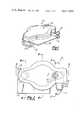
- FIG. 1is a perspective view of the pump assembly of the present invention.
- FIG. 2is a top plan view of a preferred embodiment of the pump shown in FIG. 1.
- FIG. 3is a cross-sectional view of the assembly of FIG. 2 taken along the lines of 3--3 of FIG. 2 and showing the upper and lower body members sealed into an assembly by the diaphragm interfitted therebetween.
- FIG. 4is a sectional view of the diaphragm-covered central portion of the pump of FIG. 2 and taken along the lines 4--4 thereof.
- FIG. 5is a sectional view of the outlet conduit showing the outlet flapper valve in closed position against the lower closure portion of the upper body member, and taken along the line 5--5 of FIG. 2.
- FIG. 6is a sectional view of the inlet conduit showing the inlet flapper valve in closed position against the closure portion of the upper surface of the lower body member and taken along the line 6--6 of FIG. 2.
- FIG. 7is a sectional view of the injection site located in the upper wall of the upper body member of FIG. 3 and taken along the line 7--7 of FIG. 2.
- FIG. 8is an exploded cross-sectional view of the cross-sectional assembly of FIG. 3 modified to include the preferred molded components and preformed diaphragm prior to assembly and including, from top to bottom, the injection site, upper body member, diaphragm securing ring, diaphragm shown with a preferred form of integral means for fixed attachment of a diaphragm reciprocator, and the lower body member.
- FIG. 9is a view looking up at the inner surfaces in the upper body member seen in cross section in FIG. 8.
- FIG. 10is a view looking down at the top surfaces of the lower body member seen in cross section in FIG. 8 and modified for easy attachment to an artificial kidney.
- FIG. 11is a bottom end view of the assembled pump of FIG. 2 oriented as in normal use position with the inlet blood conduit at the bottom and the outlet conduit at the top.
- FIG. 12is a top view of the diaphragm securing ring of FIG. 8.
- FIG. 13is a bottom view of the diaphragm securing ring of FIG. 8.
- FIG. 14is a cross-sectional view of the ring of FIG. 12 and taken along the line 14--14 thereof.
- FIG. 15is a cross-sectional view of the ring of FIG. 12 and taken along the line 15--15 thereof.
- FIG. 16is an enlargement of the attachment groove in the ring of FIG. 12 which joins the ring and upper body member into a single element upon sealing during assembly, taken along the line 16--16 thereof.
- FIG. 17is an enlargement of one of the grooves in the lower surface of the ring of FIG. 13 which mates with protrusions on the diaphragm of FIG. 8 to seal the upper and lower body members into a unit and to sealingly isolate the inlet and outlet conduits from the distensible central portion of the diaphragm.
- FIG. 18is a top view of the diaphragm seal and flapper valve member of FIG. 3.
- FIG. 19is a cutaway enlargement of a section of the upper body member in the area of the inlet conduit at the left hand side of FIG. 3 and showing in dotted lines the flapper valve in open position against the stop located on the lower wall of the upper body member and in the central portion of the flapper valve opposite the single web attaching the flapper to the diaphragm.
- FIG. 20is a cutaway enlargement of a section of the lower body member as seen in FIG. 5 and showing in dotted lines the flapper valve in open position against the stop in the center of the outlet conduit and attached to the diaphragm by a single web in line with the longitudinal axis of the outlet conduit.
- the assembly generally designated 10 as shown in the drawingscomprises a concave upper body housing 12, a lower body generally designated 14 and a flexible diaphragm and sealing member generally designated 16 that is interfitted and secured between the mating surfaces of the upper and lower body members as best seen in FIG. 3.
- the upper bodyis fabricated as two separate moldings, as shown in FIG. 8, and results from sealing the diaphragm support generally designated 18 to upper housing 12 along all mating edge surfaces to form an integral one-piece upper body as seen in FIG. 3.
- the lower body 14comprises a single molding including an integral blood inlet conduit 28 and an outlet conduit 30 located on opposite sides of the diaphragm plunger opening 32, an administration site 33 for heparin injection or the like, and an attachment wing 35, or flange, for securing the assembly to an artificial kidney.
- blood cavity 20is defined by the inner wall 17 of upper housing 12, the upper surfaces of diaphragm support 18 and the exposed upper surface 19 of diaphragm 16.
- Blood cavity 20includes a centrally located hemispherical portion 22 having on one side an inlet portion 24 and on the other side an outlet portion 26, which side portions are adjacent to inlet conduit 28 and outlet conduit 30, respectively.
- Diaphragm 16is supported on and secured between the mating upper surface contact portions of lower body 14 and the lower surface contact surface portions of diaphragm support 18. As assembled, diaphragm 16 serves the dual functions of a diaphragm and sealing gasket to isolate inlet and outlet conduits 28, 30 from blood cavity 20 and from the central, distensible portion 19 of diaphragm 16 which overlies plunger opening 32 in lower body 14 and penetrates into blood cavity 20 from the solid line to the dotted line positions shown in FIG. 4.
- lower body 14is priovided on its upper surface with circular vee-shaped groove 34 which surrounds opening 36 at the upper end of inlet conduit 28, and with a similar vee-shaped groove 38 which surrounds opening 40 at the upper end of outlet conduit 30.
- the pairs of grooves 34, 42 and 38, 44are sized to receive and form an interference, sealing fit with slightly larger vee-shaped protrusions 46, 48 on each surface of diaphragm 16.
- the upper surface of lower body 14is also provided with an arcuate groove 50 which is slightly larger in diameter than opening 32.
- Groove 50together with opposing arcuate groove 52 in the lower surface of diaphragm support 18, upon assembly as shown in FIG. 3, sealingly engages and supports the slightly larger spherical protrusion 54A on diaphragm 16.
- the side portions of protrusion 54Aextend outwardly from each surface of diaphragm 16 and have the cross-sectional shape of a truncated hemisphere.
- groove 52 in diaphragm support 18is spaced slightly outwardly from the inner opening 57 defined by inwardly extending wall portion 55 of diaphragm support 18. Opening 57 is somewhat larger in diameter than opening 32 in lower body member 14 and wall 55 terminates on its lower surface in an abrupt radiused corner portion 56, preferably in the range of about 15° to 35° of the tangent to the radius from a vertical plane.
- corner portion 56supportingly engages the upper contacting surface 19 and permits the diaphragm to distend in a smooth arc into cavity 20, as indicated by the dotted line portion illustrated in FIG. 4.
- Flapper valves 37, 41as best seen in FIG. 18, comprise circular flapper portions 54, 56, respectively, each of which is attached to diaphragm 16 by a web 58, 60, respectively.
- Webs 58, 60are thin relative to the diaphragm thickness and small relative to the size of the flapper portions 54, 56 and secure them to the diaphragm through a highly flexible pivot having low resistance to pivoting motion to open and close conduit openings 36, 40.
- flapper valves 37, 41open and close in response to small forces due to blood flow, or minor pressure changes, at the instant of direction change in the reciprocation of diaphragm 16.
- Each web 58, 60is located in line with, and on the center line of, the longitudinal axis of its associated blood conduit 28, 30, FIGS. 3, 5.
- This location of web 60allows flapper portion 56 of flapper valve 41 to freely pivot and move from its closed position in contact with the lower peripheral closure surface 62 of upper body 12 surrounding outlet opening 40 of outlet conduit 30, FIG. 5, to its open position in contact with stop 66 as seen in FIG. 20.
- the in-line location of web 58allows flapper portion 54 to freely pivot and move, at the same instant, from its open position in contact with stop 68, FIG. 19, to its closed position in contact with upper peripheral closure surface 64 of lower body 14, FIG. 6.
- Diaphragm 16should be flexible, resistant to extension set, compatible with blood and have high fatigue resistance to repeated flexing. Silicone rubber is a preferred material from which to form a diaphragm, but other flexible polymeric materials such as ethylene-propylene rubbers are also satisfactory. The flexibility of the diaphragm will vary with thickness and diameter of opening 32 and, as an example, for silicone rubber may have a thickness of about 0.020 to 0.080 inches for a diameter of opening 32 of about 1 to 2 inches.
- a typical flapper 54, 56may have a diameter of 3/16 to 5/16 inch and for a preferred diaphragm thickness of 0.040 inches the web is advantageously thinned to about 0.008 to 0.015 inch, preferably about 0.010 inch, with a web length of about three to six times its thickness, preferably about 0.05 inch.
- Flapper valve stops 66, 68prevent excessive pivoting of flappers 41 and 37, to attain their open positions because of the relatively close location that leaves only a small space from the adjacent surface of the flapper when it is in its closed position. Such location nevertheless permits free, unrestrained blood flood through openings 40, 36 but concurrently insures easy, positive closure with only a slight degree of reversal of blood flow direction toward or from the flapper valve 37, 41.
- Stops 66, 68are formed with smooth surfaces and present a gently curving projection from inner wall 17 and from the inner surface of outlet conduit 30, FIGS. 3, 5 and 6. Each stop 66, 68 is located so that when each of the flapper valves 41 and 37 is in its open position, the stops support flapper portions 56, 54 along the diametral plane which is in line with, and bisects, webs 60 and 58, respectively.
- the blood pump of this inventionis surprisingly small, light in weight, and relatively easily fabricated from three plastic molded parts and a resilient diaphragm.
- the pump sizeis surprising when it is considered that it pumps blood at the rate of 150 to 350 cubic centimeters per minute for four to six hour periods per hemodialysis treatment and is capable of use for more than one treatment.
- a number of moldable thermoplastic materialsare suitable for use in making the pump. The most important requirements are blood compatibility, ease of molding and sealing, and low cost. It is desirable to employ a transparent or translucent material so that blood flow can be easily monitored and observed during use.
- Polystyreneis a preferred material.
- Other thermoplastic polymerssuch as acrylics or styreneacrylonitrile polymers are also satisfactory.
- FIG. 8The preferred embodiments of styrene molded component elements which form the unitary assembly of this invention are shown in FIG. 8.
- injection site cap 70 and rubber insert 72are first positioned into injection site opening 74, which is provided with a smaller diameter central needle opening 76, and joined together, preferably by ultrasonic welding of cap 70 to upper body housing 12.
- Diaphragm support ring 18is then positioned in contact with housing 12 and ultrasonically welded along the mating surfaces to form the integral upper body shown in FIG. 3.
- Diaphragm 16is then positioned on lower body 14 and pressed into contact with the upper body assembly and ultrasonically sealed along all mating surface edges to form the pump assembly 10.
- Diaphragm 16, illustrated in FIGS. 3 and 4is desirably made from a selected rubber having sufficient resistance to extension set, or permanent stretching, to repetitively retract from its dotted line position to the solid line position shown in FIG. 4 due to its inherent resilience.
- Such diaphragmsmay be advanced into the blood cavity 20 by any suitable plunger or reciprocating piston, and preferably by a plunger having a diameter only slightly smaller than opening 32.
- FIG. 8A preferred form of diaphragm 16 is illustrated in FIG. 8.
- the diaphragm shown thereis modified to include integral attachment means 78 for disconnectably receiving a diaphragm plunger 80 to fixedly attach the reciprocating plunger to the diaphragm.
- integral attachment means 78for disconnectably receiving a diaphragm plunger 80 to fixedly attach the reciprocating plunger to the diaphragm.
- This constructionpermits exact replication of length of stroke and resultant degree of penetration of the diaphragm into blood cavity 20 for each reciprocation and thus assures constant, steady expulsion of identical volumes of blood on each cycle. Accurate, steady, uniform rates of blood flow are thus attained merely by altering the length, or rate of reciprocation, of the plunger.
- This preferred positive attachment of the plungerhas the advantage of producing a wider, more uniform arc of penetration into blood cavity 20 which increases volume displacement of blood at lesser inward flexure distance at the center point of the plunger, thereby decreasing fatigue or localized stretching adjacent the end of the plunger.
- the modified diaphragm shown in FIG. 8is a one-piece molding of silicone rubber.
- the distensible portion 19is increased in thickness relative to the outer flap supporting portion and on its lower side is provided with a molded extension 78 which includes a dart-shaped cavity 82 that is adapted to disconnectably receive a plunger of similar shape.
- Plunger 80as shown in FIG. 8, is provided with a dart-shaped head portion 81, and annular shaped ring 83, which are attached to the diaphragm by forcibly inserting head portion 81 into cavity 82 by spreading wing portions 84, 86 apart as the forward curved edges of plunger head 81 is snapped into locking engagement under the inwardly extending flange portion 88 of cavity 82.
- Pump 10is approximately 2 to 3 inches long, from bottom inlet conduit 28 to top outlet conduit 30.
- Inlet conduit 28is substantially wider at its mouth portion 29 than at the upper end opening 36 into blood cavity 20, and gradually tapers inwardly and upwardly as shown in FIG. 2 and FIG. 3, to thereby serve as connecting means for attaching blood supply means or integral blood pressure measuring means, if desired.
- Outlet conduit 30tapers smoothly from opening 40 to blood tube connector opening 31 and the inner walls of both tapering conduits are free from sharp projections in the path of blood flow to prevent swirling or dead spots that could cause hemolysis or clotting of the blood being pumped.
Landscapes
- Health & Medical Sciences (AREA)
- Engineering & Computer Science (AREA)
- Heart & Thoracic Surgery (AREA)
- Cardiology (AREA)
- Mechanical Engineering (AREA)
- Life Sciences & Earth Sciences (AREA)
- Biomedical Technology (AREA)
- Hematology (AREA)
- Anesthesiology (AREA)
- Animal Behavior & Ethology (AREA)
- General Health & Medical Sciences (AREA)
- Public Health (AREA)
- Veterinary Medicine (AREA)
- Urology & Nephrology (AREA)
- Pulmonology (AREA)
- General Engineering & Computer Science (AREA)
- External Artificial Organs (AREA)
- Reciprocating Pumps (AREA)
Abstract
Description
Claims (9)
Priority Applications (9)
| Application Number | Priority Date | Filing Date | Title |
|---|---|---|---|
| US06/276,752US4411603A (en) | 1981-06-24 | 1981-06-24 | Diaphragm type blood pump for medical use |
| JP57095582AJPS5849152A (en) | 1981-06-24 | 1982-06-03 | Blood pump |
| NL8202264ANL191927C (en) | 1981-06-24 | 1982-06-04 | Diaphragm pump for blood. |
| DE19823221725DE3221725C2 (en) | 1981-06-24 | 1982-06-09 | Blood pump |
| IT4868082AIT1157213B (en) | 1981-06-24 | 1982-06-21 | IMPROVEMENT IN PUMPS FOR THE EXTRACORPOREAL BLOOD CIRCULATION |
| GB08218138AGB2101232B (en) | 1981-06-24 | 1982-06-23 | Blood pump |
| CA000405794ACA1176933A (en) | 1981-06-24 | 1982-06-23 | Diaphragm type blood pump for medical use |
| FR8210947AFR2508320B1 (en) | 1981-06-24 | 1982-06-23 | BLOOD PUMP |
| BE0/208440ABE893639A (en) | 1981-06-24 | 1982-06-24 | BLOOD PUMP |
Applications Claiming Priority (1)
| Application Number | Priority Date | Filing Date | Title |
|---|---|---|---|
| US06/276,752US4411603A (en) | 1981-06-24 | 1981-06-24 | Diaphragm type blood pump for medical use |
Publications (1)
| Publication Number | Publication Date |
|---|---|
| US4411603Atrue US4411603A (en) | 1983-10-25 |
Family
ID=23057944
Family Applications (1)
| Application Number | Title | Priority Date | Filing Date |
|---|---|---|---|
| US06/276,752Expired - LifetimeUS4411603A (en) | 1981-06-24 | 1981-06-24 | Diaphragm type blood pump for medical use |
Country Status (9)
| Country | Link |
|---|---|
| US (1) | US4411603A (en) |
| JP (1) | JPS5849152A (en) |
| BE (1) | BE893639A (en) |
| CA (1) | CA1176933A (en) |
| DE (1) | DE3221725C2 (en) |
| FR (1) | FR2508320B1 (en) |
| GB (1) | GB2101232B (en) |
| IT (1) | IT1157213B (en) |
| NL (1) | NL191927C (en) |
Cited By (39)
| Publication number | Priority date | Publication date | Assignee | Title |
|---|---|---|---|---|
| US4574797A (en)* | 1983-05-09 | 1986-03-11 | Tony Christianson | Diaphragm and exhaust valve for second stage regulator |
| US4633845A (en)* | 1984-08-31 | 1987-01-06 | Schmelzer Corporation | Vacuum control device |
| US4636149A (en)* | 1985-05-13 | 1987-01-13 | Cordis Corporation | Differential thermal expansion driven pump |
| US4646781A (en)* | 1985-05-07 | 1987-03-03 | Pacesetter Infusion, Ltd. | Diaphragm valve for medication infusion pump |
| EP0288145A1 (en)* | 1987-03-17 | 1988-10-26 | Kenneth Arthur Logan | Disposable pump element for dialysis pump |
| US4842498A (en)* | 1987-01-20 | 1989-06-27 | Thomas Industries, Inc. | Diaphragm compressor |
| US4968301A (en)* | 1989-02-02 | 1990-11-06 | Imed Corporation | Disposable infusion device |
| US5098262A (en)* | 1990-12-28 | 1992-03-24 | Abbott Laboratories | Solution pumping system with compressible pump cassette |
| US5108373A (en)* | 1989-09-25 | 1992-04-28 | Baxter International Inc. | Intravenous metering device |
| US5129794A (en)* | 1990-10-30 | 1992-07-14 | Hewlett-Packard Company | Pump apparatus |
| US5190527A (en)* | 1989-09-25 | 1993-03-02 | Baxter International Inc. | Intravenous metering device |
| US5266016A (en)* | 1989-09-18 | 1993-11-30 | Tecumseh Products Company | Positive stop for a suction leaf valve of a compressor |
| US5267964A (en)* | 1992-03-23 | 1993-12-07 | Clintec Nutrition Co. | Fluid control device including automatic valve |
| WO1994016226A1 (en)* | 1992-12-30 | 1994-07-21 | Abbott Laboratories | Diaphragm for solution pumping system |
| US5344292A (en)* | 1992-08-20 | 1994-09-06 | Ryder International Corporation | Fluid pumping system and apparatus |
| US5368570A (en)* | 1991-11-12 | 1994-11-29 | Imed Corporation | Apparatus for infusing medical solutions |
| US5431634A (en)* | 1992-03-06 | 1995-07-11 | Baxter International Inc. | Ambulatory pump |
| US5462256A (en)* | 1994-05-13 | 1995-10-31 | Abbott Laboratories | Push button flow stop useable with a disposable infusion pumping chamber cassette |
| USD364210S (en) | 1994-07-19 | 1995-11-14 | Drummond Industries | Transparent sump pump check valve |
| US5585011A (en)* | 1993-10-04 | 1996-12-17 | Research International, Inc. | Methods for manufacturing a filter |
| US5586868A (en)* | 1994-05-13 | 1996-12-24 | Abbott Laboratories | Method of delivering liquid to a patient via a disposable pumping cassette having a flow control & pressure monitoring member |
| US6173959B1 (en)* | 1996-02-14 | 2001-01-16 | Mikuni Adec Corporation | Diaphragm-holding synthetic resin assembly |
| WO2002004046A3 (en)* | 2000-07-07 | 2002-06-13 | Fluidsense Corp | Infusion pump cassette |
| US6460539B1 (en) | 2000-09-21 | 2002-10-08 | 3M Innovative Properties Company | Respirator that includes an integral filter element, an exhalation valve, and impactor element |
| US20020170563A1 (en)* | 1992-05-29 | 2002-11-21 | Japuntich Daniel A. | Filtering face mask that has a new exhalation valve |
| US20030209475A1 (en)* | 1991-04-19 | 2003-11-13 | Connell Mark E. | Methods for providing kidney dialysis equipment and services |
| US20040001766A1 (en)* | 2002-05-14 | 2004-01-01 | Maianti Edgardo Costa | Unit for pumping fluid, particularly blood |
| US7117868B1 (en)* | 1992-05-29 | 2006-10-10 | 3M Innovative Properties Company | Fibrous filtration face mask having a new unidirectional fluid valve |
| US20070119459A1 (en)* | 1992-05-29 | 2007-05-31 | 3M Innovative Properties Company | Method Of Making A Filtering Face Mask Having New Exhalation Valve |
| US20070191763A1 (en)* | 2006-02-13 | 2007-08-16 | Trimed Ag | Milk pump |
| US20080171970A1 (en)* | 2006-11-01 | 2008-07-17 | Luzbetak Mark A | Self returning contamination barrier |
| US20090270799A1 (en)* | 2008-04-24 | 2009-10-29 | Seiko Epson Corporation | Fluid injection device |
| US20100086419A1 (en)* | 2007-03-13 | 2010-04-08 | Medela Holding Ag | Membrane Suction Pump Unit |
| US8323492B2 (en) | 2007-10-24 | 2012-12-04 | Baxter International Inc. | Hemodialysis system having clamping mechanism for peristaltic pumping |
| GB2502342A (en)* | 2012-05-25 | 2013-11-27 | Richard Weatherley | Disposable diaphragm pump |
| CN104707196A (en)* | 2015-03-25 | 2015-06-17 | 上海工程技术大学 | Peritoneum dialysis apparatus |
| US9072843B2 (en) | 2003-11-05 | 2015-07-07 | Baxter International Inc. | Renal therapy system having pump reversing fluid control |
| US10578098B2 (en) | 2005-07-13 | 2020-03-03 | Baxter International Inc. | Medical fluid delivery device actuated via motive fluid |
| US11478578B2 (en) | 2012-06-08 | 2022-10-25 | Fresenius Medical Care Holdings, Inc. | Medical fluid cassettes and related systems and methods |
Families Citing this family (17)
| Publication number | Priority date | Publication date | Assignee | Title |
|---|---|---|---|---|
| JPS61216661A (en)* | 1985-03-23 | 1986-09-26 | Fujiya Shokuhin:Kk | Marine algae-containing tamagodofu (food of egg and tofu (bean curd)) and production thereof |
| US4759264A (en)* | 1985-11-18 | 1988-07-26 | Critikon, Inc. | Parenteral solution diaphragm pump |
| IT1275135B (en)* | 1995-02-06 | 1997-07-30 | Dideco Spa | PULSATILE PUMPING EQUIPMENT FOR LIQUIDS, IN PARTICULAR BLOOD. |
| GB2301151B (en)* | 1995-05-15 | 1999-02-03 | Pirelli Tyres Ltd | Diaphragm pump |
| DE10224750A1 (en) | 2002-06-04 | 2003-12-24 | Fresenius Medical Care De Gmbh | Device for the treatment of a medical fluid |
| JP2005006709A (en)* | 2003-06-16 | 2005-01-13 | Naigai Kasei Kk | Medical cap |
| WO2011008858A1 (en) | 2009-07-15 | 2011-01-20 | Fresenius Medical Care Holdings, Inc. | Medical fluid cassettes and related systems and methods |
| DE102010019057A1 (en)* | 2010-05-03 | 2011-11-03 | Wmf Württembergische Metallwarenfabrik Ag | fluid pump |
| WO2012087798A2 (en) | 2010-12-20 | 2012-06-28 | Fresenius Medical Care Holdings, Inc. | Medical fluid cassettes and related systems and methods |
| US9624915B2 (en) | 2011-03-09 | 2017-04-18 | Fresenius Medical Care Holdings, Inc. | Medical fluid delivery sets and related systems and methods |
| MX341315B (en) | 2011-04-21 | 2016-08-12 | Fresenius Medical Care Holdings Inc | Medical fluid pumping systems and related devices and methods. |
| US9500188B2 (en) | 2012-06-11 | 2016-11-22 | Fresenius Medical Care Holdings, Inc. | Medical fluid cassettes and related systems and methods |
| US9561323B2 (en) | 2013-03-14 | 2017-02-07 | Fresenius Medical Care Holdings, Inc. | Medical fluid cassette leak detection methods and devices |
| US10117985B2 (en) | 2013-08-21 | 2018-11-06 | Fresenius Medical Care Holdings, Inc. | Determining a volume of medical fluid pumped into or out of a medical fluid cassette |
| DE102014103459A1 (en)* | 2014-03-13 | 2015-09-17 | Pfeiffer Vacuum Gmbh | diaphragm pump |
| JPWO2019208016A1 (en)* | 2018-04-24 | 2021-02-25 | 株式会社村田製作所 | Valves and fluid controls with valves |
| US10837435B1 (en)* | 2020-03-10 | 2020-11-17 | Douglas D. Myers | High-volume diaphragm with geometrically enhanced reinforcement |
Citations (8)
| Publication number | Priority date | Publication date | Assignee | Title |
|---|---|---|---|---|
| US2378613A (en)* | 1941-12-01 | 1945-06-19 | Arrowhead Rubber Company | Fuel tank flapper valve |
| US3058140A (en)* | 1960-06-10 | 1962-10-16 | Vdo Schindling | Manually operated collapsible wall pump for window-washers in automotive vehicles |
| US3145659A (en)* | 1962-08-31 | 1964-08-25 | Briggs & Stratton Corp | Suction actuated fuel pump |
| US3514231A (en)* | 1967-12-01 | 1970-05-26 | Perry Belden | Reciprocating pump for marine toilets |
| US3610698A (en)* | 1968-05-15 | 1971-10-05 | Jean Gachot | Compressed air brake systems for vehicles |
| US3802807A (en)* | 1972-06-02 | 1974-04-09 | Precision Control Prod Corp | Pump |
| US4051852A (en)* | 1975-06-26 | 1977-10-04 | The Kendall Company | Aspirating device |
| DE2639992A1 (en)* | 1976-09-04 | 1978-03-09 | Sigdell Jan Erik Dr | Infusion pump and flow meter - has single diaphragm for pump and inlet and outlet valves |
Family Cites Families (13)
| Publication number | Priority date | Publication date | Assignee | Title |
|---|---|---|---|---|
| US2769838A (en)* | 1953-11-20 | 1956-11-06 | Ciba Pharm Prod Inc | Polyglycol ether acid anilides |
| US3045605A (en)* | 1958-09-15 | 1962-07-24 | Tillotson Mfg Co | Fuel feeding means |
| US2980032A (en)* | 1959-02-27 | 1961-04-18 | Brown Engine Products Inc | Fuel pump |
| US3250224A (en)* | 1962-08-20 | 1966-05-10 | Tillotson Mfg Co | Pumping means for a charge forming apparatus |
| FR2149464B1 (en)* | 1971-08-16 | 1976-01-23 | Bentley Lab Inc Us | |
| JPS515666B2 (en)* | 1972-05-08 | 1976-02-21 | ||
| US4165208A (en)* | 1973-02-05 | 1979-08-21 | Valleylab | Intravenous delivery pump |
| US3976402A (en)* | 1974-07-15 | 1976-08-24 | Origo, Inc. | Intravenous delivery pump |
| CA1110137A (en)* | 1976-05-24 | 1981-10-06 | Ingemar H. Lundquist | Intravenous liquid pumping system and method |
| JPS5816901B2 (en)* | 1976-11-09 | 1983-04-02 | 日機装株式会社 | pulsatile blood pump |
| US4231871A (en)* | 1977-06-10 | 1980-11-04 | Cordis Dow Corp. | Artificial kidney and method for making same |
| JPS5413714A (en)* | 1977-07-01 | 1979-02-01 | Nec Corp | Multi-frequency signal reception system |
| IT1117080B (en)* | 1977-09-21 | 1986-02-10 | Bosio Roberto | PUMP SUITABLE TO CREATE AN ARTIFICIAL BLOOD CIRCULATION |
- 1981
- 1981-06-24USUS06/276,752patent/US4411603A/ennot_activeExpired - Lifetime
- 1982
- 1982-06-03JPJP57095582Apatent/JPS5849152A/enactiveGranted
- 1982-06-04NLNL8202264Apatent/NL191927C/ennot_activeIP Right Cessation
- 1982-06-09DEDE19823221725patent/DE3221725C2/ennot_activeExpired - Fee Related
- 1982-06-21ITIT4868082Apatent/IT1157213B/enactive
- 1982-06-23CACA000405794Apatent/CA1176933A/ennot_activeExpired
- 1982-06-23FRFR8210947Apatent/FR2508320B1/ennot_activeExpired
- 1982-06-23GBGB08218138Apatent/GB2101232B/ennot_activeExpired
- 1982-06-24BEBE0/208440Apatent/BE893639A/ennot_activeIP Right Cessation
Patent Citations (8)
| Publication number | Priority date | Publication date | Assignee | Title |
|---|---|---|---|---|
| US2378613A (en)* | 1941-12-01 | 1945-06-19 | Arrowhead Rubber Company | Fuel tank flapper valve |
| US3058140A (en)* | 1960-06-10 | 1962-10-16 | Vdo Schindling | Manually operated collapsible wall pump for window-washers in automotive vehicles |
| US3145659A (en)* | 1962-08-31 | 1964-08-25 | Briggs & Stratton Corp | Suction actuated fuel pump |
| US3514231A (en)* | 1967-12-01 | 1970-05-26 | Perry Belden | Reciprocating pump for marine toilets |
| US3610698A (en)* | 1968-05-15 | 1971-10-05 | Jean Gachot | Compressed air brake systems for vehicles |
| US3802807A (en)* | 1972-06-02 | 1974-04-09 | Precision Control Prod Corp | Pump |
| US4051852A (en)* | 1975-06-26 | 1977-10-04 | The Kendall Company | Aspirating device |
| DE2639992A1 (en)* | 1976-09-04 | 1978-03-09 | Sigdell Jan Erik Dr | Infusion pump and flow meter - has single diaphragm for pump and inlet and outlet valves |
Cited By (73)
| Publication number | Priority date | Publication date | Assignee | Title |
|---|---|---|---|---|
| US4574797A (en)* | 1983-05-09 | 1986-03-11 | Tony Christianson | Diaphragm and exhaust valve for second stage regulator |
| US4633845A (en)* | 1984-08-31 | 1987-01-06 | Schmelzer Corporation | Vacuum control device |
| US4646781A (en)* | 1985-05-07 | 1987-03-03 | Pacesetter Infusion, Ltd. | Diaphragm valve for medication infusion pump |
| US4636149A (en)* | 1985-05-13 | 1987-01-13 | Cordis Corporation | Differential thermal expansion driven pump |
| US4842498A (en)* | 1987-01-20 | 1989-06-27 | Thomas Industries, Inc. | Diaphragm compressor |
| EP0288145A1 (en)* | 1987-03-17 | 1988-10-26 | Kenneth Arthur Logan | Disposable pump element for dialysis pump |
| US4968301A (en)* | 1989-02-02 | 1990-11-06 | Imed Corporation | Disposable infusion device |
| US5266016A (en)* | 1989-09-18 | 1993-11-30 | Tecumseh Products Company | Positive stop for a suction leaf valve of a compressor |
| US5190527A (en)* | 1989-09-25 | 1993-03-02 | Baxter International Inc. | Intravenous metering device |
| US5108373A (en)* | 1989-09-25 | 1992-04-28 | Baxter International Inc. | Intravenous metering device |
| US5129794A (en)* | 1990-10-30 | 1992-07-14 | Hewlett-Packard Company | Pump apparatus |
| WO1992012345A1 (en)* | 1990-12-28 | 1992-07-23 | Abbott Laboratories | Solution pumping system with compressible pump cassette |
| US5098262A (en)* | 1990-12-28 | 1992-03-24 | Abbott Laboratories | Solution pumping system with compressible pump cassette |
| US20030209475A1 (en)* | 1991-04-19 | 2003-11-13 | Connell Mark E. | Methods for providing kidney dialysis equipment and services |
| US7351340B2 (en) | 1991-04-19 | 2008-04-01 | Baxter International Inc. | Methods for providing kidney dialysis equipment and services |
| US7318892B2 (en) | 1991-04-19 | 2008-01-15 | Baxter International Inc. | Method and apparatus for kidney dialysis |
| US7303680B2 (en) | 1991-04-19 | 2007-12-04 | Baxter International Inc. | Method and apparatus for kidney dialysis |
| US7264730B2 (en) | 1991-04-19 | 2007-09-04 | Baxter International Inc. | Methods for kidney dialysis |
| US20050242034A1 (en)* | 1991-04-19 | 2005-11-03 | Connell Mark E | Method and apparatus for kidney dialysis |
| US20030222022A1 (en)* | 1991-04-19 | 2003-12-04 | Connell Mark E. | Methods for kidney dialysis |
| US5368570A (en)* | 1991-11-12 | 1994-11-29 | Imed Corporation | Apparatus for infusing medical solutions |
| US5431634A (en)* | 1992-03-06 | 1995-07-11 | Baxter International Inc. | Ambulatory pump |
| AU657197B2 (en)* | 1992-03-23 | 1995-03-02 | Baxter International Inc. | Fluid control device including automatic valve |
| US5267964A (en)* | 1992-03-23 | 1993-12-07 | Clintec Nutrition Co. | Fluid control device including automatic valve |
| US6843248B2 (en) | 1992-05-29 | 2005-01-18 | 3M Innovative Properties Company | Filtering face mask that has a new exhalation valve |
| US7493900B1 (en)* | 1992-05-29 | 2009-02-24 | 3M Innovative Properties Company | Fibrous filtration face mask having a new unidirectional fluid valve |
| US7428903B1 (en)* | 1992-05-29 | 2008-09-30 | 3M Innovative Properties Company | Fibrous filtration face mask having a new unidirectional fluid valve |
| US7311104B2 (en) | 1992-05-29 | 2007-12-25 | 3M Innovative Properties Company | Method of making a filtering face mask that has an exhalation valve |
| US20070119459A1 (en)* | 1992-05-29 | 2007-05-31 | 3M Innovative Properties Company | Method Of Making A Filtering Face Mask Having New Exhalation Valve |
| US7117868B1 (en)* | 1992-05-29 | 2006-10-10 | 3M Innovative Properties Company | Fibrous filtration face mask having a new unidirectional fluid valve |
| US6854463B2 (en)* | 1992-05-29 | 2005-02-15 | 3M Innovative Properties Company | Filtering face mask that has a new exhalation valve |
| US20020170563A1 (en)* | 1992-05-29 | 2002-11-21 | Japuntich Daniel A. | Filtering face mask that has a new exhalation valve |
| US5344292A (en)* | 1992-08-20 | 1994-09-06 | Ryder International Corporation | Fluid pumping system and apparatus |
| WO1994016226A1 (en)* | 1992-12-30 | 1994-07-21 | Abbott Laboratories | Diaphragm for solution pumping system |
| US5378126A (en)* | 1992-12-30 | 1995-01-03 | Abbott Laboratories | Diaphragm cassette for solution pumping system |
| US5585011A (en)* | 1993-10-04 | 1996-12-17 | Research International, Inc. | Methods for manufacturing a filter |
| US5660728A (en)* | 1993-10-04 | 1997-08-26 | Research International, Inc. | Micromachined fluid handling apparatus with filter |
| US5702618A (en)* | 1993-10-04 | 1997-12-30 | Research International, Inc. | Methods for manufacturing a flow switch |
| US5705070A (en)* | 1993-10-04 | 1998-01-06 | Research International, Inc. | Micromachined filters |
| US5839467A (en)* | 1993-10-04 | 1998-11-24 | Research International, Inc. | Micromachined fluid handling devices |
| US5697153A (en)* | 1993-10-04 | 1997-12-16 | Research International, Inc. | Method for manufacturing a fluid flow regulator |
| US5617632A (en)* | 1993-10-04 | 1997-04-08 | Research International, Inc. | Methods for forming a contoured regulator seat |
| US5462256A (en)* | 1994-05-13 | 1995-10-31 | Abbott Laboratories | Push button flow stop useable with a disposable infusion pumping chamber cassette |
| EP0751794B1 (en)* | 1994-05-13 | 2003-07-16 | Abbott Laboratories | Disposable fluid infusion pumping chamber cassette having a push button flow stop thereon |
| US5816779A (en)* | 1994-05-13 | 1998-10-06 | Abbott Laboratories | Disposable fluid infusion pumping cassette having an interrelated flow control and pressure monitoring arrangement |
| US5586868A (en)* | 1994-05-13 | 1996-12-24 | Abbott Laboratories | Method of delivering liquid to a patient via a disposable pumping cassette having a flow control & pressure monitoring member |
| USD364210S (en) | 1994-07-19 | 1995-11-14 | Drummond Industries | Transparent sump pump check valve |
| US6173959B1 (en)* | 1996-02-14 | 2001-01-16 | Mikuni Adec Corporation | Diaphragm-holding synthetic resin assembly |
| WO2002004046A3 (en)* | 2000-07-07 | 2002-06-13 | Fluidsense Corp | Infusion pump cassette |
| US6460539B1 (en) | 2000-09-21 | 2002-10-08 | 3M Innovative Properties Company | Respirator that includes an integral filter element, an exhalation valve, and impactor element |
| US7029245B2 (en)* | 2002-05-14 | 2006-04-18 | Sorin Group Italia S.R.L. | Blood pumping unit, with a coplanar disk inlet valve and an annular outlet valve |
| US20040001766A1 (en)* | 2002-05-14 | 2004-01-01 | Maianti Edgardo Costa | Unit for pumping fluid, particularly blood |
| US9072843B2 (en) | 2003-11-05 | 2015-07-07 | Baxter International Inc. | Renal therapy system having pump reversing fluid control |
| US9872950B2 (en) | 2003-11-05 | 2018-01-23 | Baxter International Inc. | Renal therapy system having pump reversing fluid control |
| US12392335B2 (en) | 2005-07-13 | 2025-08-19 | Baxter International Inc. | Medical fluid pumping system having backflow prevention |
| US11384748B2 (en) | 2005-07-13 | 2022-07-12 | Baxter International Inc. | Blood treatment system having pulsatile blood intake |
| US10670005B2 (en) | 2005-07-13 | 2020-06-02 | Baxter International Inc. | Diaphragm pumps and pumping systems |
| US10590924B2 (en) | 2005-07-13 | 2020-03-17 | Baxter International Inc. | Medical fluid pumping system including pump and machine chassis mounting regime |
| US10578098B2 (en) | 2005-07-13 | 2020-03-03 | Baxter International Inc. | Medical fluid delivery device actuated via motive fluid |
| US20070191763A1 (en)* | 2006-02-13 | 2007-08-16 | Trimed Ag | Milk pump |
| US8142392B2 (en) | 2006-02-13 | 2012-03-27 | Trimed Ag | Milk pump |
| USD773643S1 (en) | 2006-11-01 | 2016-12-06 | Medela Holding Ag | Self returning contamination barrier |
| US9814809B2 (en) | 2006-11-01 | 2017-11-14 | Medela Holding Ag | Self returning contamination barrier |
| US8187227B2 (en) | 2006-11-01 | 2012-05-29 | Medela Holding Ag | Self returning contamination barrier |
| US11642441B2 (en) | 2006-11-01 | 2023-05-09 | Medela Holding Ag | Self returning contamination barrier |
| US20080171970A1 (en)* | 2006-11-01 | 2008-07-17 | Luzbetak Mark A | Self returning contamination barrier |
| US20100086419A1 (en)* | 2007-03-13 | 2010-04-08 | Medela Holding Ag | Membrane Suction Pump Unit |
| US8323492B2 (en) | 2007-10-24 | 2012-12-04 | Baxter International Inc. | Hemodialysis system having clamping mechanism for peristaltic pumping |
| US20090270799A1 (en)* | 2008-04-24 | 2009-10-29 | Seiko Epson Corporation | Fluid injection device |
| US20140161644A1 (en)* | 2012-05-25 | 2014-06-12 | Richard Weatherley | Diaphragm Pump |
| GB2502342A (en)* | 2012-05-25 | 2013-11-27 | Richard Weatherley | Disposable diaphragm pump |
| US11478578B2 (en) | 2012-06-08 | 2022-10-25 | Fresenius Medical Care Holdings, Inc. | Medical fluid cassettes and related systems and methods |
| CN104707196A (en)* | 2015-03-25 | 2015-06-17 | 上海工程技术大学 | Peritoneum dialysis apparatus |
Also Published As
| Publication number | Publication date |
|---|---|
| GB2101232A (en) | 1983-01-12 |
| NL191927B (en) | 1996-07-01 |
| JPS5849152A (en) | 1983-03-23 |
| BE893639A (en) | 1982-10-18 |
| CA1176933A (en) | 1984-10-30 |
| JPH0255051B2 (en) | 1990-11-26 |
| FR2508320B1 (en) | 1986-11-21 |
| IT8248680A0 (en) | 1982-06-21 |
| DE3221725C2 (en) | 1994-11-03 |
| DE3221725A1 (en) | 1983-01-13 |
| IT1157213B (en) | 1987-02-11 |
| NL8202264A (en) | 1983-01-17 |
| NL191927C (en) | 1996-11-04 |
| GB2101232B (en) | 1985-04-11 |
| FR2508320A1 (en) | 1982-12-31 |
Similar Documents
| Publication | Publication Date | Title |
|---|---|---|
| US4411603A (en) | Diaphragm type blood pump for medical use | |
| US4381005A (en) | Intravenous pump chamber | |
| CA1272921A (en) | Parenteral solution diaphragm pump | |
| US4222407A (en) | One-way flex valve | |
| US4290346A (en) | Intravenous pump chamber | |
| US4712583A (en) | Precision passive flat-top valve for medication infusion system | |
| JP3628700B2 (en) | Push button flow stopper for use with disposable infusion pumping chamber cassette | |
| US4915017A (en) | Diaphragm and a diaphragm-actuated fluid-transfer control device | |
| US5254086A (en) | Medical lavage apparatus and methods | |
| JP3628699B2 (en) | Disposable infusion pumping chamber cassette with push button flow stopper thereon | |
| US4181245A (en) | Casette for use with an I.V. infusion controller | |
| US5647575A (en) | Volumetric shaft/valve | |
| US4515591A (en) | Disposable syringe cartridge for fluid delivery apparatus | |
| US10172992B2 (en) | System for performing peritoneal dialysis | |
| RU2456497C1 (en) | Non-return valve, diaphragm pump and sphygmomanometre | |
| EP0452045B1 (en) | Normally closed duckbill valve assembly | |
| US5568912A (en) | Sliding flow controller having channel with variable size groove | |
| US4725207A (en) | Automated peritoneovenous shunt | |
| JPS59111765A (en) | Injection pump apparatus | |
| GB2085732A (en) | Administration set | |
| WO1996008666A9 (en) | Sliding flow controller having channel with variable size groove | |
| JPS63315060A (en) | Disposable pump element for pump apparatus | |
| CA1148823A (en) | One-way valve for parenteral apparatus | |
| CN222798236U (en) | An integrated one-way valve and its micro diaphragm pump | |
| JPS6022945B2 (en) | blood pump |
Legal Events
| Date | Code | Title | Description |
|---|---|---|---|
| AS | Assignment | Owner name:CONTINENTAL ILLINOIS NATIONAL BANK AND TRUST COMPA Free format text:SECURITY INTEREST;ASSIGNOR:CORDIS DOW CORP.;REEL/FRAME:004075/0624 Effective date:19821221 | |
| AS | Assignment | Owner name:CORDIS DOW CORP., 999 BRICKELL AVE, MIAMI, FL 331 Free format text:ASSIGNMENT OF ASSIGNORS INTEREST.;ASSIGNOR:KELL, MICHAEL J.;REEL/FRAME:004138/0624 Effective date:19810615 | |
| STCF | Information on status: patent grant | Free format text:PATENTED CASE | |
| AS | Assignment | Owner name:CORDIS DOW CORP. A DE CORP. Free format text:RELEASED BY SECURED PARTY;ASSIGNOR:CONTINENTAL ILLINOIS NATIONAL BANK AND TRUST COMPANY;REEL/FRAME:004196/0444 Effective date:19830902 | |
| MAFP | Maintenance fee payment | Free format text:PAYMENT OF MAINTENANCE FEE, 4TH YEAR, PL 96-517 (ORIGINAL EVENT CODE: M170); ENTITY STATUS OF PATENT OWNER: LARGE ENTITY Year of fee payment:4 | |
| FEPP | Fee payment procedure | Free format text:MAINTENANCE FEE REMINDER MAILED (ORIGINAL EVENT CODE: REM.); ENTITY STATUS OF PATENT OWNER: LARGE ENTITY | |
| FEPP | Fee payment procedure | Free format text:SURCHARGE FOR LATE PAYMENT, PL 96-517 (ORIGINAL EVENT CODE: M176); ENTITY STATUS OF PATENT OWNER: LARGE ENTITY | |
| MAFP | Maintenance fee payment | Free format text:PAYMENT OF MAINTENANCE FEE, 8TH YEAR, PL 96-517 (ORIGINAL EVENT CODE: M171); ENTITY STATUS OF PATENT OWNER: LARGE ENTITY Year of fee payment:8 | |
| MAFP | Maintenance fee payment | Free format text:PAYMENT OF MAINTENANCE FEE, 12TH YEAR, LARGE ENTITY (ORIGINAL EVENT CODE: M185); ENTITY STATUS OF PATENT OWNER: LARGE ENTITY Year of fee payment:12 | |
| AS | Assignment | Owner name:BAXTER INTERNATIONAL INC., ILLINOIS Free format text:ASSIGNMENT OF ASSIGNORS INTEREST;ASSIGNOR:ALTHIN MEDICAL, INC.;REEL/FRAME:011369/0689 Effective date:20001219 |