US4411055A - Vascular guiding catheter assembly and vascular dilating catheter assembly and a combination thereof and methods for making the same - Google Patents
Vascular guiding catheter assembly and vascular dilating catheter assembly and a combination thereof and methods for making the sameDownload PDFInfo
- Publication number
- US4411055A US4411055AUS06/291,233US29123381AUS4411055AUS 4411055 AUS4411055 AUS 4411055AUS 29123381 AUS29123381 AUS 29123381AUS 4411055 AUS4411055 AUS 4411055A
- Authority
- US
- United States
- Prior art keywords
- tubular member
- catheter assembly
- tubular
- annular portion
- inflatable annular
- Prior art date
- Legal status (The legal status is an assumption and is not a legal conclusion. Google has not performed a legal analysis and makes no representation as to the accuracy of the status listed.)
- Expired - Lifetime
Links
- 230000000916dilatatory effectEffects0.000titleclaimsabstractdescription67
- 238000000034methodMethods0.000titleclaimsabstractdescription35
- 230000002792vascularEffects0.000titleabstractdescription5
- 239000000463materialSubstances0.000claimsabstractdescription24
- 239000012530fluidSubstances0.000claimsabstractdescription14
- 239000002654heat shrinkable materialSubstances0.000claimsabstractdescription5
- 239000007788liquidSubstances0.000claimsdescription18
- 238000004891communicationMethods0.000claimsdescription13
- 238000010438heat treatmentMethods0.000claimsdescription12
- 239000004033plasticSubstances0.000claimsdescription6
- 238000002844meltingMethods0.000claimsdescription4
- 230000008018meltingEffects0.000claimsdescription4
- 230000015572biosynthetic processEffects0.000claimsdescription3
- 238000013022ventingMethods0.000claimsdescription2
- 238000001816coolingMethods0.000claims4
- 229920000098polyolefinPolymers0.000abstractdescription8
- 238000009530blood pressure measurementMethods0.000abstractdescription2
- 238000001802infusionMethods0.000abstractdescription2
- 239000004809TeflonSubstances0.000description10
- 229920006362Teflon®Polymers0.000description10
- 210000004351coronary vesselAnatomy0.000description8
- 230000010339dilationEffects0.000description8
- 210000001105femoral arteryAnatomy0.000description6
- 238000011010flushing procedureMethods0.000description6
- 210000000709aortaAnatomy0.000description5
- 229910052751metalInorganic materials0.000description5
- 239000002184metalSubstances0.000description5
- 208000031481Pathologic ConstrictionDiseases0.000description4
- 239000002872contrast mediaSubstances0.000description4
- 238000004519manufacturing processMethods0.000description4
- 230000036262stenosisEffects0.000description4
- 208000037804stenosisDiseases0.000description4
- 238000002399angioplastyMethods0.000description3
- 210000004204blood vesselAnatomy0.000description3
- 238000010276constructionMethods0.000description3
- 238000002347injectionMethods0.000description3
- 239000007924injectionSubstances0.000description3
- 230000003902lesionEffects0.000description3
- 238000007789sealingMethods0.000description3
- 229910052782aluminiumInorganic materials0.000description2
- XAGFODPZIPBFFR-UHFFFAOYSA-NaluminiumChemical compound[Al]XAGFODPZIPBFFR-UHFFFAOYSA-N0.000description2
- 230000003143atherosclerotic effectEffects0.000description2
- 239000008280bloodSubstances0.000description2
- 210000004369bloodAnatomy0.000description2
- 230000035602clottingEffects0.000description2
- PCHJSUWPFVWCPO-UHFFFAOYSA-NgoldChemical compound[Au]PCHJSUWPFVWCPO-UHFFFAOYSA-N0.000description2
- 239000010931goldSubstances0.000description2
- 229910052737goldInorganic materials0.000description2
- 210000004013groinAnatomy0.000description2
- 210000004165myocardiumAnatomy0.000description2
- 229920000642polymerPolymers0.000description2
- 229910001220stainless steelInorganic materials0.000description2
- 239000010935stainless steelSubstances0.000description2
- 206010002383Angina PectorisDiseases0.000description1
- 206010003210ArteriosclerosisDiseases0.000description1
- 208000037260Atherosclerotic PlaqueDiseases0.000description1
- 206010053567CoagulopathiesDiseases0.000description1
- HTTJABKRGRZYRN-UHFFFAOYSA-NHeparinChemical compoundOC1C(NC(=O)C)C(O)OC(COS(O)(=O)=O)C1OC1C(OS(O)(=O)=O)C(O)C(OC2C(C(OS(O)(=O)=O)C(OC3C(C(O)C(O)C(O3)C(O)=O)OS(O)(=O)=O)C(CO)O2)NS(O)(=O)=O)C(C(O)=O)O1HTTJABKRGRZYRN-UHFFFAOYSA-N0.000description1
- 241000282414Homo sapiensSpecies0.000description1
- FAPWRFPIFSIZLT-UHFFFAOYSA-MSodium chlorideChemical compound[Na+].[Cl-]FAPWRFPIFSIZLT-UHFFFAOYSA-M0.000description1
- 208000007536ThrombosisDiseases0.000description1
- 230000002159abnormal effectEffects0.000description1
- 239000003146anticoagulant agentSubstances0.000description1
- 229940127219anticoagulant drugDrugs0.000description1
- 210000002376aorta thoracicAnatomy0.000description1
- 210000001367arteryAnatomy0.000description1
- 230000001174ascending effectEffects0.000description1
- 230000000712assemblyEffects0.000description1
- 238000000429assemblyMethods0.000description1
- QVGXLLKOCUKJST-UHFFFAOYSA-Natomic oxygenChemical compound[O]QVGXLLKOCUKJST-UHFFFAOYSA-N0.000description1
- 230000000740bleeding effectEffects0.000description1
- 230000017531blood circulationEffects0.000description1
- 238000002586coronary angiographyMethods0.000description1
- 238000004132cross linkingMethods0.000description1
- 230000000694effectsEffects0.000description1
- 150000002148estersChemical class0.000description1
- 239000011888foilSubstances0.000description1
- 229960002897heparinDrugs0.000description1
- 229920000669heparinPolymers0.000description1
- 238000001990intravenous administrationMethods0.000description1
- 230000005865ionizing radiationEffects0.000description1
- 238000002690local anesthesiaMethods0.000description1
- 239000003550markerSubstances0.000description1
- 230000000877morphologic effectEffects0.000description1
- 229910052760oxygenInorganic materials0.000description1
- 239000001301oxygenSubstances0.000description1
- 238000004806packaging method and processMethods0.000description1
- 230000002093peripheral effectEffects0.000description1
- 238000002360preparation methodMethods0.000description1
- 230000000750progressive effectEffects0.000description1
- 230000003014reinforcing effectEffects0.000description1
- 238000004513sizingMethods0.000description1
- 238000005476solderingMethods0.000description1
- 230000002966stenotic effectEffects0.000description1
- 230000001954sterilising effectEffects0.000description1
- BFKJFAAPBSQJPD-UHFFFAOYSA-NtetrafluoroetheneChemical groupFC(F)=C(F)FBFKJFAAPBSQJPD-UHFFFAOYSA-N0.000description1
Images


Classifications
- A—HUMAN NECESSITIES
- A61—MEDICAL OR VETERINARY SCIENCE; HYGIENE
- A61M—DEVICES FOR INTRODUCING MEDIA INTO, OR ONTO, THE BODY; DEVICES FOR TRANSDUCING BODY MEDIA OR FOR TAKING MEDIA FROM THE BODY; DEVICES FOR PRODUCING OR ENDING SLEEP OR STUPOR
- A61M25/00—Catheters; Hollow probes
- A61M25/10—Balloon catheters
- A61M25/1027—Making of balloon catheters
- A61M25/1036—Making parts for balloon catheter systems, e.g. shafts or distal ends
- A—HUMAN NECESSITIES
- A61—MEDICAL OR VETERINARY SCIENCE; HYGIENE
- A61M—DEVICES FOR INTRODUCING MEDIA INTO, OR ONTO, THE BODY; DEVICES FOR TRANSDUCING BODY MEDIA OR FOR TAKING MEDIA FROM THE BODY; DEVICES FOR PRODUCING OR ENDING SLEEP OR STUPOR
- A61M25/00—Catheters; Hollow probes
- A61M25/01—Introducing, guiding, advancing, emplacing or holding catheters
- A61M25/0105—Steering means as part of the catheter or advancing means; Markers for positioning
- A61M25/0108—Steering means as part of the catheter or advancing means; Markers for positioning using radio-opaque or ultrasound markers
- A—HUMAN NECESSITIES
- A61—MEDICAL OR VETERINARY SCIENCE; HYGIENE
- A61M—DEVICES FOR INTRODUCING MEDIA INTO, OR ONTO, THE BODY; DEVICES FOR TRANSDUCING BODY MEDIA OR FOR TAKING MEDIA FROM THE BODY; DEVICES FOR PRODUCING OR ENDING SLEEP OR STUPOR
- A61M25/00—Catheters; Hollow probes
- A61M25/10—Balloon catheters
- A61M25/1018—Balloon inflating or inflation-control devices
- A61M25/10181—Means for forcing inflation fluid into the balloon
- A61M25/10182—Injector syringes
- A—HUMAN NECESSITIES
- A61—MEDICAL OR VETERINARY SCIENCE; HYGIENE
- A61M—DEVICES FOR INTRODUCING MEDIA INTO, OR ONTO, THE BODY; DEVICES FOR TRANSDUCING BODY MEDIA OR FOR TAKING MEDIA FROM THE BODY; DEVICES FOR PRODUCING OR ENDING SLEEP OR STUPOR
- A61M25/00—Catheters; Hollow probes
- A61M25/10—Balloon catheters
- A61M25/1025—Connections between catheter tubes and inflation tubes
- A—HUMAN NECESSITIES
- A61—MEDICAL OR VETERINARY SCIENCE; HYGIENE
- A61M—DEVICES FOR INTRODUCING MEDIA INTO, OR ONTO, THE BODY; DEVICES FOR TRANSDUCING BODY MEDIA OR FOR TAKING MEDIA FROM THE BODY; DEVICES FOR PRODUCING OR ENDING SLEEP OR STUPOR
- A61M25/00—Catheters; Hollow probes
- A61M25/10—Balloon catheters
- A61M25/1027—Making of balloon catheters
- A61M25/1029—Production methods of the balloon members, e.g. blow-moulding, extruding, deposition or by wrapping a plurality of layers of balloon material around a mandril
- A—HUMAN NECESSITIES
- A61—MEDICAL OR VETERINARY SCIENCE; HYGIENE
- A61M—DEVICES FOR INTRODUCING MEDIA INTO, OR ONTO, THE BODY; DEVICES FOR TRANSDUCING BODY MEDIA OR FOR TAKING MEDIA FROM THE BODY; DEVICES FOR PRODUCING OR ENDING SLEEP OR STUPOR
- A61M25/00—Catheters; Hollow probes
- A61M25/10—Balloon catheters
- A61M25/1027—Making of balloon catheters
- A61M25/1034—Joining of shaft and balloon
- A—HUMAN NECESSITIES
- A61—MEDICAL OR VETERINARY SCIENCE; HYGIENE
- A61M—DEVICES FOR INTRODUCING MEDIA INTO, OR ONTO, THE BODY; DEVICES FOR TRANSDUCING BODY MEDIA OR FOR TAKING MEDIA FROM THE BODY; DEVICES FOR PRODUCING OR ENDING SLEEP OR STUPOR
- A61M25/00—Catheters; Hollow probes
- A61M25/10—Balloon catheters
- A61M25/104—Balloon catheters used for angioplasty
- A—HUMAN NECESSITIES
- A61—MEDICAL OR VETERINARY SCIENCE; HYGIENE
- A61M—DEVICES FOR INTRODUCING MEDIA INTO, OR ONTO, THE BODY; DEVICES FOR TRANSDUCING BODY MEDIA OR FOR TAKING MEDIA FROM THE BODY; DEVICES FOR PRODUCING OR ENDING SLEEP OR STUPOR
- A61M29/00—Dilators with or without means for introducing media, e.g. remedies
- A61M29/02—Dilators made of swellable material
- B—PERFORMING OPERATIONS; TRANSPORTING
- B23—MACHINE TOOLS; METAL-WORKING NOT OTHERWISE PROVIDED FOR
- B23P—METAL-WORKING NOT OTHERWISE PROVIDED FOR; COMBINED OPERATIONS; UNIVERSAL MACHINE TOOLS
- B23P11/00—Connecting or disconnecting metal parts or objects by metal-working techniques not otherwise provided for
- B23P11/02—Connecting or disconnecting metal parts or objects by metal-working techniques not otherwise provided for by first expanding and then shrinking or vice versa, e.g. by using pressure fluids; by making force fits
- A—HUMAN NECESSITIES
- A61—MEDICAL OR VETERINARY SCIENCE; HYGIENE
- A61B—DIAGNOSIS; SURGERY; IDENTIFICATION
- A61B17/00—Surgical instruments, devices or methods
- A61B17/22—Implements for squeezing-off ulcers or the like on inner organs of the body; Implements for scraping-out cavities of body organs, e.g. bones; for invasive removal or destruction of calculus using mechanical vibrations; for removing obstructions in blood vessels, not otherwise provided for
- A61B2017/22001—Angioplasty, e.g. PCTA
- A—HUMAN NECESSITIES
- A61—MEDICAL OR VETERINARY SCIENCE; HYGIENE
- A61M—DEVICES FOR INTRODUCING MEDIA INTO, OR ONTO, THE BODY; DEVICES FOR TRANSDUCING BODY MEDIA OR FOR TAKING MEDIA FROM THE BODY; DEVICES FOR PRODUCING OR ENDING SLEEP OR STUPOR
- A61M25/00—Catheters; Hollow probes
- A61M25/0043—Catheters; Hollow probes characterised by structural features
- A61M25/0045—Catheters; Hollow probes characterised by structural features multi-layered, e.g. coated
- A61M2025/0046—Coatings for improving slidability
- A61M2025/0047—Coatings for improving slidability the inner layer having a higher lubricity
- A61M2025/0048—Coatings for improving slidability the inner layer having a higher lubricity with an outer layer made from silicon
- A—HUMAN NECESSITIES
- A61—MEDICAL OR VETERINARY SCIENCE; HYGIENE
- A61M—DEVICES FOR INTRODUCING MEDIA INTO, OR ONTO, THE BODY; DEVICES FOR TRANSDUCING BODY MEDIA OR FOR TAKING MEDIA FROM THE BODY; DEVICES FOR PRODUCING OR ENDING SLEEP OR STUPOR
- A61M25/00—Catheters; Hollow probes
- A61M25/10—Balloon catheters
- A61M2025/1043—Balloon catheters with special features or adapted for special applications
- A61M2025/1079—Balloon catheters with special features or adapted for special applications having radio-opaque markers in the region of the balloon
- A—HUMAN NECESSITIES
- A61—MEDICAL OR VETERINARY SCIENCE; HYGIENE
- A61M—DEVICES FOR INTRODUCING MEDIA INTO, OR ONTO, THE BODY; DEVICES FOR TRANSDUCING BODY MEDIA OR FOR TAKING MEDIA FROM THE BODY; DEVICES FOR PRODUCING OR ENDING SLEEP OR STUPOR
- A61M25/00—Catheters; Hollow probes
- A61M25/0043—Catheters; Hollow probes characterised by structural features
- A61M25/0045—Catheters; Hollow probes characterised by structural features multi-layered, e.g. coated
- Y—GENERAL TAGGING OF NEW TECHNOLOGICAL DEVELOPMENTS; GENERAL TAGGING OF CROSS-SECTIONAL TECHNOLOGIES SPANNING OVER SEVERAL SECTIONS OF THE IPC; TECHNICAL SUBJECTS COVERED BY FORMER USPC CROSS-REFERENCE ART COLLECTIONS [XRACs] AND DIGESTS
- Y10—TECHNICAL SUBJECTS COVERED BY FORMER USPC
- Y10T—TECHNICAL SUBJECTS COVERED BY FORMER US CLASSIFICATION
- Y10T29/00—Metal working
- Y10T29/49—Method of mechanical manufacture
- Y10T29/49826—Assembling or joining
- Y10T29/49863—Assembling or joining with prestressing of part
- Y10T29/49865—Assembling or joining with prestressing of part by temperature differential [e.g., shrink fit]
Definitions
- This techniqueconsists of a catheter system introduced via the femoral artery under local anesthesia.
- a preshaped guiding catheteris positiond into the orifice of the coronary artery and through this catheter a second dilation catheter is advanced into the branches of the coronary artery.
- the dilation catheterhas an elliptical-shaped distensible balloon portion near the tip which can be inflated and deflated.
- the distensible portionis inflated with fluid which compresses the atherosclerotic material in a direction generally perpendicular to the wall of the vessel thereby dilating the lumen of the vessel.
- Peripheral arterial lesions treated by this techniquehave demonstrated by morphological studies that the atheroma can be compressed leaving a smooth luminal surface noted at the time of restudy.
- the patency rate two years following dilation of iliac and femoropopliteal atherosclerotic lesionswas greater than 70%.
- the continued success of this techniquecould greatly widen the horizons for coronary angiography and provide another treatment for patients with angina pectoris.
- the present inventionis directed to a guiding catheter assembly and dilating catheter assembly and methods for making the same so that they have the desired characteristics and so that they can be made uniformly and without undue expense with volume production being possible.
- Another object of the inventionis to provide a guiding catheter assembly of the above character which has sufficient rigidity so that it can be readily manuevered.
- Another object of the inventionis to provide a method for making the guiding catheter assembly which utilizes heat-shrinkable tubing in the form of an irradiated modified polyolefin for providing the additional rigidity required.
- Another object of the inventionis to provide a dilating catheter assembly which can be readily inserted through the guiding catheter assembly.
- Another object of the inventionis to provide a dilating catheter assembly of the above character in which an inflatable or distensible balloon-like portion is formed integral with one of the tubular members forming the dilating catheter assembly.
- Another object of the inventionis to provide a dilating catheter assembly of the above character in which the balloon-like portion can be readily and reliably formed.
- Another object of the inventionis to provide a dilating catheter assembly of the above character in which the balloon can be readily inflated with a radiographic contrast liquid and can be rapidly deflated.
- Another object of the inventionis to provide a dilating catheter assembly of the above character which can be readily inflated with a radiographic contrast liquid being flushed out of the balloon as it is being filled.
- Another object of the inventionis to provide a method for forming the dilating catheter assembly which utilizes heat-shrinkable tubing for the formation of the balloon-like portion and for forming the passage leading to the balloon.
- Another object of the inventionis to provide a dilating catheter assembly of the above character in which the catheter is formed of an irradiated modified polyolefin tubing.
- Another object of the inventionis to provide a dilating catheter assembly of the above character in which inner and outer coaxial tubular members are provided and in which a distal pressure seal is formed between the inner and outer tubular members solely by heating the outer heat shrinkable tubular member.
- Another object of the inventionis to provide a method for making a dilating catheter assembly in which the balloon-like portion can be readily and easily formed.
- Another object of the inventionis to provide a method for making a dilating catheter assembly which is reliable and which lends itself to quantity production.
- Another object of the inventionis to provide a method for inflating the balloon of the dilating catheter assembly with a radiographic contrast liquid and venting any air in the balloon out of the balloon by utilizing a separate flow passage for the escape of air.
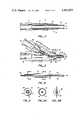
- FIG. 1is a perspective view of a dilator, a guiding catheter assembly, a dilating catheter assembly and a balloon flushing tube and showing the manner in which they are used with respect to each other and incorporated into assemblies for performing coronary percutaneous transluminal angioplasty.
- FIG. 2is a cross-sectional view taken along the line 2--2 of the guiding catheter assembly.
- FIG. 3is a cross-sectional view taken along the line 3--3 of the dilating catheter assembly.
- FIG. 4is a cross-sectional view taken along the line 4--4 of the dilating catheter assembly.
- FIG. 5is a cross-sectional view taken along the line 5--5 of FIG. 4.
- FIGS. 6A and 6Bare taken along the line 6--6 of FIG. 5 and show the balloon in inflated end deflated conditions respectively.
- FIGS. 7A, 7B, 7C and 7Dillustrate the steps utilized in one method for forming the balloon from the irradiated modified polyolefin tubing utilized for the dilating catheter assembly.
- FIGS. 8A and 8Billustrate the steps in another method utilized for forming the balloon on the outer catheter of the dilating catheter assembly.
- FIGS. 9A and 9Bshow the steps utilized in the method for forming the inner catheter of the dilating catheter assembly.
- FIGS. 10A and 10Bshow the steps in the method of inserting the inner tubular member into the outer tubular member having a balloon formed therein and shrinking the distal end of the outer tubular member onto the distal end of the inner tubular member to provide an air-tight adhesive-free seal and providing a flow passage through which fluid can be introduced into the balloon for inflating the same and withdrawing it from the balloon for deflating the same.
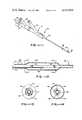
- FIG. 11is an isometric view of another embodiment of our dilating catheter assembly incorporating the present invention.
- FIG. 12is a cross-sectional view taken along the line 12--12 of FIG. 11.
- FIG. 13is a cross-sectional view taken from the line 13--13 of FIG. 12.
- FIG. 14is a cross-sectional view taken along the line 14--14 of FIG. 12.
- the guiding catheter assembly 21 shown in FIG. 1consists of first and second coaxial tubular members 22 and 23.
- the first tubular memberis formed of a material which has an extremely low coefficient of friction as for example TFE Teflon (a tetrafluoroethylene polymer) having a coefficient of friction of approximately 0.02.
- TFE Teflona tetrafluoroethylene polymer
- the coefficient of frictioncan range from as low a value as possible to 0.05. It is also desirable that the material utilized for the first tubular member have a certain amount of flexibility.
- the first tubular memberhas a guiding passageway 24 having an internal diameter of approximately 0.075 of an inch. It also can have a suitable wall thickness preferably in the vicinity of 0.004 of an inch. However, these dimensions can vary within the range of approximately ⁇ 15% and still be satisfactory.
- TFE Teflon utilized for the first tubular memberwas very desirable because it had a very low coefficient of friction, it was found, however, that it was too flexible with thin walls to serve as a guiding catheter because it could not be properly manipulated in the body of the patient. It is for this reason that the second tubular member 23 is provided.
- This second tubular memberis formed of a heat-shrinkable irradiated modified polyolefin supplied by Raychem Corporation of Menlo Park, Calif.
- the heat shrinkable tubing selectedhad an internal diameter of 0.120 of an inch which was of a sufficient size so that the first tubular member could be readily inserted into the same.
- the second tubular member of the assembled first and second tubular members 22 and 23was then progressively heated along its length in a suitable manner such as by a hot air tool to a suitable temperature as for example 120° C. to cause the second or outer tubular member 23 to shrink in a manner well known to those skilled in the art so that it forms a tight seal with respect to the first tubular member 22.
- a suitable temperatureas for example 120° C.
- thiscan be accomplished by passing the assembled first and second tubular members through a cylindrical heating unit to cause progressive heating of the second tubular member.
- the assemblyis provided with proximal and distal ends 25 and 26.
- the distal endis provided with bends to form a shape identical to the standard coronary catheter.
- a left coronary guiding catheteris formed by providing two bends 27 and 28 of approximately 120°-150° (proximal) and 60°-90° (distal) each in the same direction to provide the bends which are shown in FIG. 1 for a left coronary artery.
- the distal endcan be cut off to the desired length and thereafter, the distal end can be sanded or smoothed in a suitable manner.
- An annular recess 30is formed on the extreme distal end of the tubular member 23.
- For a right coronary guiding cathetera single bend 29 as shown by the broken lines in FIG. 1 can be provided.
- An attachment or fitting 31is secured to the proximal end of the first and second tubular member in a suitable manner.
- the attachment or fitting 31is in the form of a female Luer fitting or attachment having a metal cylindrical extension 32 on which there is crimped a metal band 33.
- the first or inner tubular member 22is inserted into the cylindrical extension 32 and the second or outer tubular member 23 is slipped over the cylindrical extension 32 and the band 33.
- a sleeve 34 also formed of a similar heat-shrinkable tubingis thereafter slid over the outer or second tubular member 23 and the fitting 31.
- the sleeve 34is then heated to a suitable temperature as for example 120° C. to cause it to shrink over the fitting 31 and also over the proximal end of the first and second tubular members 22 and 23 to form an excellent leakproof adhesive-free connection between the parts.
- the material which is utilized for the second tubular member 23has a substantially higher coefficient of friction than the material utilized for the first tubular member 22.
- thisis not objectionable since the second tubular member will be inserted into the blood vessel over a wire in a standard percutaneous technique and thus will be lubricated by the blood in the vessel.
- the use of the guiding catheter assemblywill be described in conjunction with the dilating catheter assembly hereinafter described.
- the guiding catheter assembly 21has a suitable length which is tailored to the purpose for which it is used. As for example, when utilizing the same for doing coronary percutaneous transluminal angioplasty on adults, a length of 95-110 cm. is utilized.
- the dilating catheter assembly 36 as shown in FIG. 1,consists of first and second tubular members 37 and 38.
- the first and second tubular members 37 and 38are formed of heat-shrinkable tubing of the type hereinbefore described manufactured by Raychem Corporation of Menlo Park, Calif.
- the first tubular member 37is provided with a flow passage 39 extending the length of the same.
- the first tubular member 37is coaxially disposed within the second tubular member in such a manner so that the second tubular member surrounds the first tubular member.
- the combined first and second tubular members 37 and 38have a proximal end 41 and a distal end 42.
- the second tubular member 38has formed therein a balloon-like or inflatable annular portion 43 near the distal end 42 of the first and second tubular members 37 and 38.
- An annular flow passage 44is formed between the second tubular member 38 and extends from the proximal end into the balloon-like or inflatable annular portion 43 to permit the introduction of fluid into the balloon-like portion 43 for inflating the balloon-like portion and for withdrawing fluid from the same for deflating the balloon-like portion.
- the method by which the assembly consisting of the first and second tubular members 37 and 38 with the balloon-like portion 43 and the passages 39 and 44 formed therein ismanufacturedcan be seen by reference to FIGS. 7A through 7D.
- the second tubular member 38has an initial inside diameter of 0.065 inches and an initial outside diameter of 0.085 inches.
- the manufacture of heat-shrinkable tubingis accomplished by extruding a modified polyolefin to a predetermined size and utilizing high energy ionizing radiation to cause cross-linking of the polymer chains to occur. Thereafter, the tubing is expanded to a suitable ratio such as 2:1.
- a mandrel 46 in the form of a Teflon tubeis inserted into the tubular member 38 as shown in FIG. 7A.
- the member 38is then progressively heated as shown in FIG. 7B to shrink the member 38 down onto the mandrel 46 so that it has an inside diameter of approximately 0.058 inches and an outside diameter of 0.072 inches with a wall thickness of 0.007 inches.
- the steps shown in FIGS. 7A and 7Bare only carried out to provide a tubular member 38 of the desired size. Alternatively this can be accomplished by producing initially a heat-shrinkable tubing of the desired size.
- the mandrel 46is withdrawn to the position shown in FIG.
- the mandrel 46extends substantially the entire length of the second tubular member 38 which can have a suitable length ranging from 105 to 120 cm.
- the mandrel 47is spaced from mandrel 46 to provide a space 49 through which the balloon-like portion 43 is to be formed.
- the other mandrel 47serves as a support for supporting the distal end of the second tubular member 38.
- the second tubular member 38is then heated to a suitable temperature as for example 120° C.
- the balloon-like portion 43is formed by expanding that portion of the tubing 38 surrounding the space 49 to its elastic limit which generally corresponds to a ratio of 4 or 5 to 1 from the original extruded irradiated tubing size prior to the initial expansion.
- the balloon-like portion 43 thus formedpreferably has dimensions ranging in length from approximately 1 to 2 centimeters and an outside diameter ranging from 0.120 to 0.140 inches and a wall thickness ranging from 0.002 to 0.004 inches.
- the balloon-like portion 43can be formed as shown in FIGS. 8A and 8B.
- the mandrel 46can be removed and another mandrel 53 having holes 54 inserted into the distal end. Heat is then applied to the tubular member on opposite ends of the holes 54 to shrink the tubular member 38 so that it forms air-tight seals with the mandrel 38.
- the proximal end of the member 38is clamped and air is introduced into the distal end after the member 38 has been heated in the vicinity of the holes to a temperature beyond the crystalline melting point and a balloon-like portion 43 is formed in the manner hereinbefore described. Thereafter, the mandrel 53 can be removed.
- the balloon-like portionis permitted to cool to room temperature while the pressure is maintained in the balloon so that the temperature of the material falls below its crystalline melting point to thereby retain a semi-permanent distensible balloon-like portion 43 within the second tubular member adjacent the distal end thereof.
- the Teflon mandrels 46 and 47are removed to provide a second or outer sheath.
- the first or inner tubular member 37is formed by taking a tube of heat-shrinkable tubing of the type hereinbefore described having an outside diameter of 0.05 and having an inside diameter 0.030 having a suitable length as for example approximately 110 cm. and placing within the same a Teflon coated guide wire (or a Teflon mandrel) 56 having an outside diameter of 0.021 inches as shown in FIG. 9A.
- the first tubular member 37 with the guide wire 56 therein which serves as a mandrelis heated to a suitable temperature as for example 125° C. and stretched to cause the first tubular member 37 to shrink down onto the guide wire 56 as shown in FIG. 9B.
- the assembly which is shown in FIG. 9Bis then taken and inserted into the outer sheath or tubular member 38 which is shown in FIG. 10A. It extends beyond both ends of the outer sheath and passes through the balloon portion 43.
- the balloon-like portion 43is then covered with a cover 59 of a suitable type such as aluminum foil for protecting the balloon-like portion 43 from heat.
- the portion of the second tubular member 38 from the balloon-like portion 43 to the distal endis heated to a suitable temperature as for example 125° C. to cause the outer tubular member 38 to shrink tightly onto the first tubular member 37 with the Teflon guide wire or mandrel 56 therein to provide a fluid tight adhesive-free seal between the first and second tubular members 37 and 38.
- the mandrel 56is removed to provide the construction hereinbefore described that is, a first tubular member 37 with a flow passage 39 therein and a second tubular member 38 coaxial with tubular member 37 with an annular flow passage 44 therein extending from the proximal end into the balloon portion 43.
- the proximal ends of the first and second tubular members 37 and 38 as shown in FIG. 3are inserted into an adapter body 66.
- the body 66is formed of a suitable material such as metal or plastic and is provided with a centrally disposed bore 67 which opens through a female Luer type fitting 68.
- the adapter body 66is also provided with a threaded cylindrical projection 69 and a generally conical portion 72 which projects beyond the threaded projection 69.
- the adapter body 66is provided with a side arm 76 which is provided with a cylindrical bore 77 that extends into the bore 67 at a suitable angle as for example an angle of approximately 30°.
- a well 78is formed in the side arm 76 and is provided with an internally threaded portion 79 and a conical-shaped recess 81.
- the first or inner tubular member 37is placed in contact with a fitting 86.
- the fitting 86is provided with a cylindrical bore 87.
- the fitting 86is in the form of a conventional female-type Luer fitting.
- the fitting 86is provided with a threaded projection 88 which engages the internal threads 79. It is also provided with a conical projection 89 which is adapted to seat against the conical recess 81.
- the inner tubular member 37is brought into engagement with the inner end of a conical bore 91 provided in the threaded portion 88 and the conical portion 89 of the fitting 86 and is thus in communication with the cylindrical bore 87.
- Suitable meansis provided with maintaining the flow passage 39 in the first tubular member 37 in communication with the conical bore 91 and consists of a heat-shrinkable tubular member 92 which is secured to the proximal end of the first tubular member 37.
- Member 92is provided for the purpose of reinforcing the proximal end of the tubular member 37.
- Another heat-shrinkable tubular member 93which has a flared outer end is shrunk onto the tubular member 92 and is fitted onto the conical projection 89 and is firmly held in place by threading of the fitting 86 into the side arm 76.
- a heat shrinkable tubular member 96 having a flared outer endis secured to the proximal end of the second tubular member 38.
- the flared outer end of the tubular member 96is then positioned over the conical portion 72 of the adapter body 66 and is held in place by a collar 97 which is provided with a well 98 having an internally threaded portion 99 and a conical recess 101 against which the conical projection 72 is adapted to seat to firmly grip the flared portion of the tubular member 96.
- First and second syringes 106 and 107are adapted to be placed in the fittings 86 and 68 as shown particularly in FIG. 1.
- the syringes 106 and 107are of a conventional type and therefore will not be described in detail.
- the distal endcan be cut to the proper length and then ground to provide a smooth tapered distal end.
- the balloon flushing tube 111which is also shown in FIG. 1 consists of a long tubular member 112 formed of a suitable material such as stainless steel and having a length ranging from 36 to 40 inches. By way of an example, it can have an outside diameter of 0.020 inch and an internal diameter of 0.10 inch.
- the tubing 112has its proximal end connected to a conventional female Luer-type fitting 113 formed of a suitable material such as aluminum.
- the tubular member 112can be secured to the fitting 113 by soldering or by a crimp fit.
- a dilator 116which is shown in FIG. 1 is of a conventional type and consists of a flexible tube 117 formed of plastic and having a tapered distal end 118 having an outside diameter of 0.080 inches and an inside diameter of 0.040 inches.
- a female Luer-type fitting 119is secured to the proximal end of the tube 117.
- a flexible Teflon coated guide wire 121 of a conventional type with an outside diameter of 0.038 inchesis adapted to be inserted through the dilator 116 as shown.
- the patientis brought into a sterile environment and is prepared by sterilizing one of the groins.
- the dilating catheter assembly 36is checked. Normally, the dilating catheter assembly 36 would be supplied with the balloon flushing tube 111 in place. However if this is not the case, the balloon flushing tube 111 can be inserted through the passage 44 until it enters into the balloon 43.
- a syringe (not shown) filled with a radiographic contrast liquidinserted into the fitting 113 and the fluid is introduced into the balloon 43 to fill the balloon at the same time to flush out any air bubbles which may exist in the balloon or in the passage or lumen 44 leading to and from the balloon.
- the balloon flushing tube 111can then be removed and as soon as it is removed, a syringe 107 is placed in the fitting 68 and is filled with a radiographic contrast liquid.
- the operations thus far describedhave taken place outside the body of the patient.
- the inflation and deflation of the balloon 43can be readily checked merely by operating the syringe 107.
- a conventional pressure gauge and pressure regulator 115are provided associated with the syringe 107 so that one can ascertain and limit the pressure being applied to the balloon 43 to approximately 45 to 80 psi.
- the guiding catheter 21can be inserted into the patient in a standard percutaneous technique.
- the guiding catheter 21has been designed so that it can enter into one of either the right or left femoral arteries.
- a needleis inserted into the femoral artery and the Teflon covered guide wire 121 is inserted through the needle and through the femoral artery into the aorta.
- the movement of the guide wire and positioning thereofis observed with conventional fluoroscopic techniques. It is positioned so that its tip is generally at the level of the diaphragm of the patient which is essentially half way up the aorta.
- the dilator 116is positioned in the guiding catheter assembly 21 so that the flexible tapered tip 118 projects from the distal end of the guiding catheter assembly 21.
- the distal end of the guiding catheter assembly 21is then straightened out and the dilator and the guiding catheter 21 are passed over the guide wire which is already in place and is then introduced into the femoral artery.
- the guiding catheteris then passed up along the guide wire using the guide wire as a guide to the descending aorta or arch of the aorta.
- the operationis under continuous fluoroscopic control.
- the dilator carried by the end of the guiding catheter assemblyis radiopaque and therefore can be easily visualized radiographically.
- the guiding catheteris inserted until the distal end of the catheter is at the desired point which will generally be in the ascending portion of the aorta several centimeters from the coronary artery ostium.
- the guide wire and the dilatorcan be removed from the guiding catheter and the guiding catheter will be aspirated to remove any debris then flushed with radiopaque contrast medium. Thereafter, the catheter can be flushed with a saline solution or contrast medium.
- the patientcan be given intravenous heparin in a standard dose to act as a anticoagulant and to prevent any abnormal thrombosis or blood clot formation on the catheter or in the areas of catheter entry.
- the guiding catheter assembly 21can then be filled with a radiographic contrast material such as Renographin 76 and the catheter can be advanced until it engages into the left main coronary ostium which is the artery to be utilized.
- the positioning of the guiding cathetercan be confirmed by one or more injections of the contrasting liquid into the coronary vessel in which fluoroscopic observations are taking place.
- the dilating catheter assembly 36can be inserted.
- the balloon 43is completely deflated as shown in FIG. 6B. When it is deflated, it may assume the position shown by broken lines in FIG. 6B so that the dilating catheter assembly 36 can be readily inserted into the guiding catheter assembly 21.
- the guiding catheter assembly 21is formed of a first tubular member which is formed of a material having a low coefficient of friction, it is possible to push the dilating catheter assembly 36 through the entire length of the guiding catheter assembly 21 so that it will protrude out of the distal tip of the guiding catheter assembly by suitable distance such as 5 or 6 cm. and protrude into the left main coronary orifice.
- the balloon 43is positioned in one of the closest portions of the vessel the aorta and then gradually under fluoroscopic control is advanced to the point where the narrowing has been previously documented to exist. The balloon is then appropriately positioned in the narrowed portion.
- a small guide wirecan be utilized if desired. If such is the case, a small guide wire can be inserted through the sidearm 76 and through the first tubular member 37 so it extends just to the distal portion of the dilating catheter assembly 36 or slightly beyond it.
- the small guide wirecan be removed and the syringe 106 having a radiographic contrast liquid therein can be mounted on the side arm 76 and small injections of the contrasting liquid can be introduced into the first inner tubular member 37 through the passage 39 to document the position of the distal end of the dilating catheter assembly 36.
- the guide wirecan be reinserted at any time to be used as an aid in guiding the dilating catheter into the vessel that has previously demonstrated that it is subject to a stenosis or narrowing.
- pressurecan be applied by the use of the hand syringe 107 to inflate the balloon to a suitable pressure as for example from 3 to 5 atmospheres.
- the inflation of the ballooncan be visualized radiographically because the balloon is filled with a radiographic contrast liquid.
- the balloonwould be inflated for a period ranging from 2 to 5 seconds and then deflated rapidly and removed from the stenosis at which time a second coronary contrast injection can be made either through the guiding catheter itself or through the passage 39 of the inner catheter 37.
- the inflation of the ballooncauses dilation of the material deposited in the wall of the vessel by causing elongation of the material along the wall and compressing of the material against the wall so that the end result is an increased blood vessel lumen size with increased blood flow to provide an improved oxygen delivery to the jeopardized portion of the heart muscle or myocardium.
- the procedurecan be repeated as many times as deemed necessary either on the same site or at a stenosis or narrowing in a second vessel.
- the dilating catheter assembly 36can be removed.
- the guiding catheter assembly 21can be removed merely by pulling it out of the femoral artery.
- the groinis held firmly to prevent any bleeding until clotting has been accomplished.
- the patientcan then be returned to his room and instructed to remain at bed rest with the legs straight and flat for approximately six hours after which normal routine activity can be undertaken by the patient.
- a dilating catheter assembly 36can be provided which only utilizes a single tubular member with a balloon near its distal end.
- the first tubular member 37can be omitted, and the tubular member which is utilized can be shrunk down to the final desired size onto mandrels prior to formation of the balloon portion.
- the dilating catheter assembly 141consists of first and second tubular members 142 and 143.
- the first and second tubular members 142 and 143are formed of heat shrinkable material of the type hereinbefore described manufactured by Raychem Corporation of Menlo Park, Calif.
- the first tubular member 142is provided with a flow passage 144 extending the length of the same.
- the first tubular member 137is coaxially disposed within the second tubular member 143 in such a manner so that the second tubular member surrounds the first tubular member.
- the sizing of the members 142 and 143is such that an annular flow passage 146 is provided between the outer surface of the first tubular member 142 and the inner surface of the second tubular member.
- the combined first and second tubular members 142 and 143have a proximal end 147 and a distal end 148.
- the second tubular memberis provided with a distensible or inflatable annular portion or segment 149 which is adjacent the distal end 148.
- the dilating catheter assembly 141is manufactured in a manner very similar to that described for the dilating catheter assembly 36.
- the outer extremities of the members 142 and 143are fused or bonded together as shown in FIGS. 11 and 12 to provide a fluid tight seal between the outer extremities of the first and second members 142 and 143.
- the annular flow passage 146 between the inner surface of the member 143 and the outer surface of the member 142provides a flow passage which is in communication with the interior of the inflatable annular portion 149 and the proximal end 147.
- the proximal end 147 of the combined first and second tubular members 142 and 143is inserted into an adapter body 151 similar to the adapter body 66 with the principal difference being that the adapter body 66 is formed of metal and the adapter body 151 is formed of plastic.
- the adapter body 151is provided with a side arm 152.
- Another adapter body 153is mounted on the adapter body 151 and is also provided with a side arm 154.
- the side arms 152 and 154are provided with conventional Luer-type fittings.
- a flexible tubular member 156which can be called a flush tube into the flow passage 146 between the first and second tubular members 142 and 143 so that it is in communication with the interior of the distensible annular portion 149 and also extends out of the proximal end 147 of the combined first and second tubular members 142 and 143 and preferably so that it extends out of the adapter bodies of 151 and 153 as shown in FIG. 11.
- the tubular member or flush wire 156is provided with a flow passage 157 through which air can readily pass when radiographic contrast medium is introduced into the flow passage 146 through port 154.
- the flush wire or tubecan be constructed of a suitable material such as stainless steel and have an inside diameter of 0.004 inches and outside diameter of 0.008 inches.
- the combined first and second tubular members 142 and 143are fused and have an outside diameter of 0.035 inches and an inside diameter of 0.023 inches and a wall thickness of 0.006 inches.
- the outer memberhas an outside diameter of 0.055 inches and an inside diameter 0.043 inches with a wall thickness of 0.006 inches.
- the inner or first tubular member throughouthas an outside diameter of 0.034 inches and an inside diameter of 0.023 inches and a wall thickness of 0.0055 inches.
- the markers 161 and 162are formed of a metal ribbon which can be gold that is helically wrapped onto the first or inner tubular member 142 in two positions soaced 1.5 cm. apart, and fixed with a small amount of cyanoacylate ester. The two positions correspond generally to the two extremities of the balloon-like portion 149 as shown in FIG. 12.
- the gold ribboncan have a suitable dimension such as 0.002 inches and width of 0.010 of an inch with five wraps of the same being utilized to provide a marker.
- the adapter bodyis provided with a fitting 158 which is threaded thereon.
- the fitting 158carries a resilient siding member (not shown) disposed within the same and having a small hole therein through which the flush wire 166 extends, when the fitting 158 is threaded onto the adapter 153, the resilient sealing member is compressed against the flush wire 156 to form a liquid-tight seal between the flush wire 156 and the fitting 158.
- the fitting 158is then threaded onto the adapter 153 with the sealing member therein being compressed to form a liquid-tight seal between the flush wire 156 and the fitting 158.
- the dilating catheter assemblyis ready for packaging and is ready for use in this condition with the flush wire 156 in place.
- the radiographic contrast liquidenters the passage 146 and the annular portion 149
- air within the passage 146 and the annular portion 149is flushed out and is permitted to escape through the flush wire 156 to be vented to the atmosphere.
- This procedurecontinues until the annular portion 149 has been completely filled and is free of air. Since the annular portion 149 is outside of the body, the annular portion 149 can be readily examined visually to ascertain whether or not there are any air bubbles remaining.
- the use of the flush wire 156ensures that all air within the balloon portion 149 can escape and be vented readily.
- the flush wire 156facilitates rapid filling of the distensible annular portion 149.
- the radiographic contrast liquidmay be withdrawn from the distensible annular portion to deflate or collapse of the same. Thereafter, the adapter 143 is removed along with the flush wire 156.
- the dilating catheter assemblycan be placed in a guiding catheter assembly of the type hereinbefore described where a seal is formed around the dilating catheter assembly while it is in the guiding catheter assembly to prevent leakage of blood out around the guiding catheter assembly and also to permit the pressure of radiographic contrast liquids to be measured in the guiding catheter during the dilation procedure.
- the remainder of the procedureis the same as hereinbefore described with the previous embodiment.
- a vascular dilating catheter and an assembly thereof and method for making the samewhich makes it possible to fabricate the same utilizing quantity production techniques.
- the construction of the guiding catheter assembly and the dilating catheter assemblyis such that the methods utilized take advantage of heat-shrinkable tubing.
- the guiding catheter assemblyhas an interior surface which has a very low coefficient of friction so that the dilating catheter assembly can be readily inserted therethrough.
- the guiding catheter assemblyhas sufficient rigidity so that it can be readily manuevered.
- the dilating catheter assemblyis provided with an inflatable annular portion which is formed integral therewith which can be readily inflated and deflated through an annular passage independently from fluid infusion or pressure measurements through the inner catheter.
Landscapes
- Health & Medical Sciences (AREA)
- Life Sciences & Earth Sciences (AREA)
- Heart & Thoracic Surgery (AREA)
- Engineering & Computer Science (AREA)
- Public Health (AREA)
- General Health & Medical Sciences (AREA)
- Veterinary Medicine (AREA)
- Anesthesiology (AREA)
- Biomedical Technology (AREA)
- Hematology (AREA)
- Animal Behavior & Ethology (AREA)
- Pulmonology (AREA)
- Biophysics (AREA)
- Child & Adolescent Psychology (AREA)
- Vascular Medicine (AREA)
- Manufacturing & Machinery (AREA)
- Mechanical Engineering (AREA)
- Media Introduction/Drainage Providing Device (AREA)
Abstract
Description
Claims (6)
Priority Applications (1)
| Application Number | Priority Date | Filing Date | Title |
|---|---|---|---|
| US06/291,233US4411055A (en) | 1980-05-19 | 1981-08-10 | Vascular guiding catheter assembly and vascular dilating catheter assembly and a combination thereof and methods for making the same |
Applications Claiming Priority (2)
| Application Number | Priority Date | Filing Date | Title |
|---|---|---|---|
| US06/151,175US4323071A (en) | 1978-04-24 | 1980-05-19 | Vascular guiding catheter assembly and vascular dilating catheter assembly and a combination thereof and methods of making the same |
| US06/291,233US4411055A (en) | 1980-05-19 | 1981-08-10 | Vascular guiding catheter assembly and vascular dilating catheter assembly and a combination thereof and methods for making the same |
Related Parent Applications (1)
| Application Number | Title | Priority Date | Filing Date |
|---|---|---|---|
| US06/151,175DivisionUS4323071A (en) | 1978-04-24 | 1980-05-19 | Vascular guiding catheter assembly and vascular dilating catheter assembly and a combination thereof and methods of making the same |
Publications (1)
| Publication Number | Publication Date |
|---|---|
| US4411055Atrue US4411055A (en) | 1983-10-25 |
Family
ID=26848398
Family Applications (1)
| Application Number | Title | Priority Date | Filing Date |
|---|---|---|---|
| US06/291,233Expired - LifetimeUS4411055A (en) | 1980-05-19 | 1981-08-10 | Vascular guiding catheter assembly and vascular dilating catheter assembly and a combination thereof and methods for making the same |
Country Status (1)
| Country | Link |
|---|---|
| US (1) | US4411055A (en) |
Cited By (91)
| Publication number | Priority date | Publication date | Assignee | Title |
|---|---|---|---|---|
| US4490421A (en)* | 1983-07-05 | 1984-12-25 | E. I. Du Pont De Nemours And Company | Balloon and manufacture thereof |
| EP0213749A1 (en)* | 1985-07-30 | 1987-03-11 | Advanced Cardiovascular Systems, Inc. | Balloon dilatation catheter with advanceable non-removable guide wire |
| US4794928A (en)* | 1987-06-10 | 1989-01-03 | Kletschka Harold D | Angioplasty device and method of using the same |
| US4808164A (en)* | 1987-08-24 | 1989-02-28 | Progressive Angioplasty Systems, Inc. | Catheter for balloon angioplasty |
| WO1989003701A1 (en)* | 1987-10-27 | 1989-05-05 | Dietrich Harmjanz | Guide catheter in the form of a flexible or rigid tube |
| USRE32983E (en)* | 1983-07-05 | 1989-07-11 | E. I. Du Pont De Nemours And Company | Balloon and manufacture thereof |
| US4884573A (en)* | 1988-03-07 | 1989-12-05 | Leocor, Inc. | Very low profile angioplasty balloon catheter with capacity to use steerable, removable guidewire |
| EP0311458A3 (en)* | 1987-10-08 | 1989-12-20 | The Beth Israel Hospital Association | Laser balloon catheter |
| US4906244A (en)* | 1988-10-04 | 1990-03-06 | Cordis Corporation | Balloons for medical devices and fabrication thereof |
| US4915340A (en)* | 1987-07-24 | 1990-04-10 | Asin Seiki Kabushiki Kaisha | Power seat apparatus having a low friction transmission cable |
| US4921483A (en)* | 1985-12-19 | 1990-05-01 | Leocor, Inc. | Angioplasty catheter |
| US4927413A (en)* | 1987-08-24 | 1990-05-22 | Progressive Angioplasty Systems, Inc. | Catheter for balloon angioplasty |
| EP0172542A3 (en)* | 1984-08-22 | 1990-06-13 | Sarcem Sa | Remotely controlled catheter |
| EP0379794A1 (en)* | 1989-01-27 | 1990-08-01 | C.R. Bard, Inc. | Fast purge balloon dilatation catheter |
| US4958634A (en)* | 1987-05-06 | 1990-09-25 | Jang G David | Limacon geometry balloon angioplasty catheter systems and method of making same |
| US4963313A (en)* | 1987-11-30 | 1990-10-16 | Boston Scientific Corporation | Balloon catheter |
| US4964853A (en)* | 1987-02-27 | 1990-10-23 | Terumo Kabushiki Kaisha | Catheter equipped with expansible member |
| US4994067A (en)* | 1989-02-17 | 1991-02-19 | American Biomed, Inc. | Distal atherectomy catheter |
| USRE33561E (en)* | 1983-07-05 | 1991-03-26 | E. I. Du Pont De Nemours And Company | Balloon and manufacture thereof |
| US5033998A (en)* | 1984-01-20 | 1991-07-23 | Eliot Corday | Retrograde delivery of pharmacologic and diagnostic agents via venous circulation |
| US5071425A (en)* | 1988-09-12 | 1991-12-10 | Devices For Vascular Intervention, Inc. | Atherectomy catheter and method of forming the same |
| US5071406A (en)* | 1987-05-06 | 1991-12-10 | Jang G David | Limacon geometry balloon angioplasty catheter systems |
| US5087265A (en)* | 1989-02-17 | 1992-02-11 | American Biomed, Inc. | Distal atherectomy catheter |
| US5100385A (en)* | 1989-01-27 | 1992-03-31 | C. R. Bard, Inc. | Fast purge balloon dilatation catheter |
| US5108415A (en)* | 1988-10-04 | 1992-04-28 | Cordis Corporation | Balloons for medical devices and fabrication thereof |
| US5156612A (en)* | 1988-10-04 | 1992-10-20 | Cordis Corporation | Balloons for medical devices and fabrication thereof |
| US5163989A (en)* | 1990-08-27 | 1992-11-17 | Advanced Cardiovascular Systems, Inc. | Method for forming a balloon mold and the use of such mold |
| US5195969A (en)* | 1991-04-26 | 1993-03-23 | Boston Scientific Corporation | Co-extruded medical balloons and catheter using such balloons |
| US5236659A (en)* | 1988-10-04 | 1993-08-17 | Cordis Corporation | Tailoring expansion properties of balloons for medical devices |
| US5263932A (en)* | 1992-04-09 | 1993-11-23 | Jang G David | Bailout catheter for fixed wire angioplasty |
| US5287857A (en)* | 1992-06-22 | 1994-02-22 | David Mann | Apparatus and method for obtaining an arterial biopsy |
| EP0586717A1 (en)* | 1992-08-13 | 1994-03-16 | Terumo Kabushiki Kaisha | Endotracheal tube and the method of manufacturing it |
| US5304197A (en)* | 1988-10-04 | 1994-04-19 | Cordis Corporation | Balloons for medical devices and fabrication thereof |
| US5306246A (en)* | 1990-11-09 | 1994-04-26 | Boston Scientific Corporation | Balloon for medical catheter |
| US5315747A (en)* | 1992-10-30 | 1994-05-31 | Pameda N.V. | Method of preparing a balloon dilatation catheter |
| US5327891A (en)* | 1992-07-30 | 1994-07-12 | Rammler David H | Catheter track and catheter for diagnosis and treatment |
| US5330428A (en)* | 1991-05-14 | 1994-07-19 | Scimed Life Systems, Inc. | Dilatation catheter having a random copolymer balloon |
| US5342386A (en)* | 1992-10-26 | 1994-08-30 | Cordis Corporation | Catheter with multiple flexibilities along the shaft |
| US5342297A (en)* | 1992-07-10 | 1994-08-30 | Jang G David | Bailout receptacle for angioplasty catheter |
| US5348538A (en)* | 1992-09-29 | 1994-09-20 | Scimed Life Systems, Inc. | Shrinking balloon catheter having nonlinear or hybrid compliance curve |
| US5350358A (en)* | 1992-12-22 | 1994-09-27 | Med-Pro Design, Inc. | Bent co-axial catheter |
| US5354518A (en)* | 1993-02-11 | 1994-10-11 | Sherwood Medical Company | Method for manufacturing a fiberscopic catheter |
| US5356591A (en)* | 1988-10-04 | 1994-10-18 | Cordis Corporation | Tailoring expansion properties of balloons for medical devices |
| US5358498A (en)* | 1990-02-01 | 1994-10-25 | Deknatel Technology Corporation, Inc. | Needled suture |
| US5371934A (en)* | 1993-02-08 | 1994-12-13 | Markel Corporation | Process for making reinforced, thin-walled tubing |
| US5395335A (en)* | 1991-05-24 | 1995-03-07 | Jang; G. David | Universal mode vascular catheter system |
| US5411477A (en)* | 1990-05-11 | 1995-05-02 | Saab; Mark A. | High-strength, thin-walled single piece catheters |
| US5460787A (en)* | 1992-02-13 | 1995-10-24 | Colon; Amber M. | Apparatus and method for providing a scent |
| US5554118A (en)* | 1991-05-24 | 1996-09-10 | Jang; G. David | Universal mode vascular catheter system |
| WO1997035633A1 (en)* | 1996-03-27 | 1997-10-02 | Medtronic, Inc. | Method and apparatus for connecting tubing to barbed connectors for medical equipment |
| AU686518B2 (en)* | 1995-08-31 | 1998-02-05 | Target Therapeutics, Inc. | Bi-directional catheter |
| US5728129A (en)* | 1989-02-17 | 1998-03-17 | American Biomed, Inc. | Distal atherectomy catheter |
| US5738652A (en)* | 1991-07-16 | 1998-04-14 | Heartport, Inc. | Retrograde delivery catheter and method for inducing cardioplegic arrest |
| US5746968A (en)* | 1994-10-20 | 1998-05-05 | Interventional Technologies, Inc. | Method for manufacturing a high strength angioplasty balloon |
| US5755687A (en)* | 1997-04-01 | 1998-05-26 | Heartport, Inc. | Methods and devices for occluding a patient's ascending aorta |
| US5765568A (en)* | 1994-05-27 | 1998-06-16 | Heartport, Inc. | Catheter system and method for venting the left ventricle |
| US5769812A (en)* | 1991-07-16 | 1998-06-23 | Heartport, Inc. | System for cardiac procedures |
| US5788627A (en)* | 1994-12-08 | 1998-08-04 | Subrini; Louis | Cavernosal extension implants |
| US5792094A (en)* | 1991-07-16 | 1998-08-11 | Heartport, Inc. | Method of delivering cardioplegic fluid to a patient's heart |
| US5797877A (en)* | 1993-10-01 | 1998-08-25 | Boston Scientific Corporation | Medical device balloons containing thermoplastic elastomers |
| US5830183A (en)* | 1997-06-30 | 1998-11-03 | Schneider (Usa) Inc | Clip device for vascular catheter |
| US5976103A (en)* | 1991-09-26 | 1999-11-02 | Vas-Cath Incorporated | Dual lumen coaxial catheter |
| US6036697A (en)* | 1998-07-09 | 2000-03-14 | Scimed Life Systems, Inc. | Balloon catheter with balloon inflation at distal end of balloon |
| US6132824A (en)* | 1989-09-25 | 2000-10-17 | Schneider (Usa) Inc. | Multilayer catheter balloon |
| US6159178A (en)* | 1998-01-23 | 2000-12-12 | Heartport, Inc. | Methods and devices for occluding the ascending aorta and maintaining circulation of oxygenated blood in the patient when the patient's heart is arrested |
| US6203534B1 (en) | 1999-08-10 | 2001-03-20 | Biosense Webster, Inc. | Catheter with protective covering |
| WO2001058383A2 (en) | 2000-02-11 | 2001-08-16 | Novo Rps Ulc | Stent delivery system and method of use |
| US6299595B1 (en) | 1999-12-17 | 2001-10-09 | Advanced Cardiovascular Systems, Inc. | Catheters having rapid-exchange and over-the-wire operating modes |
| US6383173B1 (en)* | 1999-10-22 | 2002-05-07 | Roy H. Hunt | Syringe drench adapter for livestock |
| US6482172B1 (en) | 2000-02-09 | 2002-11-19 | Jeffrey J. Thramann | Flow-by channel catheter and method of use |
| US6482171B1 (en) | 1991-07-16 | 2002-11-19 | Heartport, Inc. | Multi-lumen catheter |
| US6500146B1 (en) | 1988-10-04 | 2002-12-31 | Cordis Corporation | Balloons for medical devices and fabrication thereof |
| US20030078537A1 (en)* | 1991-06-13 | 2003-04-24 | Jang G. David | Convertible mode vascular catheter system |
| US6599462B1 (en)* | 1997-06-11 | 2003-07-29 | Advanced Cardiovascular Systems, Inc. | Balloon catheter having non-bonded integral balloon and methods for its manufacture |
| US6648854B1 (en) | 1999-05-14 | 2003-11-18 | Scimed Life Systems, Inc. | Single lumen balloon-tipped micro catheter with reinforced shaft |
| US20040015151A1 (en)* | 2002-07-22 | 2004-01-22 | Chambers Technologies, Llc | Catheter with flexible tip and shape retention |
| US6685721B1 (en) | 1991-06-11 | 2004-02-03 | Advanced Cardiovascular Systems, Inc. | Catheter system with catheter and guidewire exchange |
| US6786887B2 (en) | 2001-01-26 | 2004-09-07 | Scimed Life Systems, Inc. | Intravascular occlusion balloon catheter |
| US6821287B1 (en) | 1991-05-24 | 2004-11-23 | Advanced Cardiovascular Systems, Inc. | Multi-mode vascular catheter system |
| US20050033343A1 (en)* | 2002-11-25 | 2005-02-10 | F.D. Cardio Ltd. | Catheter drive |
| US6896842B1 (en) | 1993-10-01 | 2005-05-24 | Boston Scientific Corporation | Medical device balloons containing thermoplastic elastomers |
| US7033325B1 (en)* | 1989-12-19 | 2006-04-25 | Scimed Life Systems, Inc. | Guidewire with multiple radiopaque marker sections |
| US7163715B1 (en) | 2001-06-12 | 2007-01-16 | Advanced Cardiovascular Systems, Inc. | Spray processing of porous medical devices |
| US20070282302A1 (en)* | 2003-11-25 | 2007-12-06 | F.D. Cardio Ltd | Stent Positioning Using Inflation Tube |
| US7468051B2 (en) | 2004-03-02 | 2008-12-23 | Boston Scientific Scimed, Inc. | Occlusion balloon catheter with external inflation lumen |
| US20100192956A1 (en)* | 2009-02-05 | 2010-08-05 | Covidien Ag | Method for manufacturing a cuff on plastic tube provided with an external sheath |
| CN102551842A (en)* | 2010-12-24 | 2012-07-11 | 刘衍民 | Hard lens calculus removing device |
| US20120209329A1 (en)* | 2011-02-11 | 2012-08-16 | Terumo Kabushiki Kaisha | Method for dilating between spinous processes |
| CN105081768A (en)* | 2015-08-20 | 2015-11-25 | 玉环县东美塑机有限公司 | Automatic dropping bottle assembling machine |
| US9232948B2 (en) | 2003-12-23 | 2016-01-12 | Stryker Corporation | Catheter with distal occlusion apparatus |
| WO2022192770A1 (en)* | 2021-03-12 | 2022-09-15 | Hope Medical | Balloon catheter methods of use |
Citations (5)
| Publication number | Priority date | Publication date | Assignee | Title |
|---|---|---|---|---|
| US2936491A (en)* | 1956-12-19 | 1960-05-17 | Amp Inc | Method for increasing the diameter of thermoplastic tubing |
| US3833003A (en)* | 1972-07-05 | 1974-09-03 | A Taricco | Intravascular occluding catheter |
| US3861942A (en)* | 1971-10-13 | 1975-01-21 | Eastman Kodak Co | Process for making flat photographic film product |
| US4104394A (en)* | 1975-12-15 | 1978-08-01 | Sumitomo Electric Industries, Ltd. | Method for diametrically expanding thermally contractive ptfe resin tube |
| US4195637A (en)* | 1977-10-21 | 1980-04-01 | Schneider Medintag Ag | Catheter arrangement, method of catheterization, and method of manufacturing a dilatation element |
- 1981
- 1981-08-10USUS06/291,233patent/US4411055A/ennot_activeExpired - Lifetime
Patent Citations (5)
| Publication number | Priority date | Publication date | Assignee | Title |
|---|---|---|---|---|
| US2936491A (en)* | 1956-12-19 | 1960-05-17 | Amp Inc | Method for increasing the diameter of thermoplastic tubing |
| US3861942A (en)* | 1971-10-13 | 1975-01-21 | Eastman Kodak Co | Process for making flat photographic film product |
| US3833003A (en)* | 1972-07-05 | 1974-09-03 | A Taricco | Intravascular occluding catheter |
| US4104394A (en)* | 1975-12-15 | 1978-08-01 | Sumitomo Electric Industries, Ltd. | Method for diametrically expanding thermally contractive ptfe resin tube |
| US4195637A (en)* | 1977-10-21 | 1980-04-01 | Schneider Medintag Ag | Catheter arrangement, method of catheterization, and method of manufacturing a dilatation element |
Cited By (145)
| Publication number | Priority date | Publication date | Assignee | Title |
|---|---|---|---|---|
| USRE33561E (en)* | 1983-07-05 | 1991-03-26 | E. I. Du Pont De Nemours And Company | Balloon and manufacture thereof |
| US4490421A (en)* | 1983-07-05 | 1984-12-25 | E. I. Du Pont De Nemours And Company | Balloon and manufacture thereof |
| USRE32983E (en)* | 1983-07-05 | 1989-07-11 | E. I. Du Pont De Nemours And Company | Balloon and manufacture thereof |
| US5033998A (en)* | 1984-01-20 | 1991-07-23 | Eliot Corday | Retrograde delivery of pharmacologic and diagnostic agents via venous circulation |
| EP0172542A3 (en)* | 1984-08-22 | 1990-06-13 | Sarcem Sa | Remotely controlled catheter |
| EP0213749A1 (en)* | 1985-07-30 | 1987-03-11 | Advanced Cardiovascular Systems, Inc. | Balloon dilatation catheter with advanceable non-removable guide wire |
| US4921483A (en)* | 1985-12-19 | 1990-05-01 | Leocor, Inc. | Angioplasty catheter |
| US4964853A (en)* | 1987-02-27 | 1990-10-23 | Terumo Kabushiki Kaisha | Catheter equipped with expansible member |
| US5304132A (en)* | 1987-05-06 | 1994-04-19 | Jang G David | Limacon geometry balloon angioplasty catheter systems and method of making same |
| US4958634A (en)* | 1987-05-06 | 1990-09-25 | Jang G David | Limacon geometry balloon angioplasty catheter systems and method of making same |
| US5071406A (en)* | 1987-05-06 | 1991-12-10 | Jang G David | Limacon geometry balloon angioplasty catheter systems |
| US4794928A (en)* | 1987-06-10 | 1989-01-03 | Kletschka Harold D | Angioplasty device and method of using the same |
| US4915340A (en)* | 1987-07-24 | 1990-04-10 | Asin Seiki Kabushiki Kaisha | Power seat apparatus having a low friction transmission cable |
| US4927413A (en)* | 1987-08-24 | 1990-05-22 | Progressive Angioplasty Systems, Inc. | Catheter for balloon angioplasty |
| US4808164A (en)* | 1987-08-24 | 1989-02-28 | Progressive Angioplasty Systems, Inc. | Catheter for balloon angioplasty |
| EP0311458A3 (en)* | 1987-10-08 | 1989-12-20 | The Beth Israel Hospital Association | Laser balloon catheter |
| WO1989003701A1 (en)* | 1987-10-27 | 1989-05-05 | Dietrich Harmjanz | Guide catheter in the form of a flexible or rigid tube |
| US4963313A (en)* | 1987-11-30 | 1990-10-16 | Boston Scientific Corporation | Balloon catheter |
| US4884573A (en)* | 1988-03-07 | 1989-12-05 | Leocor, Inc. | Very low profile angioplasty balloon catheter with capacity to use steerable, removable guidewire |
| US5071425A (en)* | 1988-09-12 | 1991-12-10 | Devices For Vascular Intervention, Inc. | Atherectomy catheter and method of forming the same |
| US6110142A (en)* | 1988-10-04 | 2000-08-29 | Cordis Corporation | Balloons for medical devices and fabrication thereof |
| US5449371A (en)* | 1988-10-04 | 1995-09-12 | Cordis Corporation | Balloons for medical devices |
| US5738653A (en)* | 1988-10-04 | 1998-04-14 | Cordis Corporation | Balloons for medical devices and fabrication thereof |
| US6500148B1 (en) | 1988-10-04 | 2002-12-31 | Cordis Corporation | Balloons for medical devices and fabrication thereof |
| US5108415A (en)* | 1988-10-04 | 1992-04-28 | Cordis Corporation | Balloons for medical devices and fabrication thereof |
| US5356591A (en)* | 1988-10-04 | 1994-10-18 | Cordis Corporation | Tailoring expansion properties of balloons for medical devices |
| US5156612A (en)* | 1988-10-04 | 1992-10-20 | Cordis Corporation | Balloons for medical devices and fabrication thereof |
| US4906244A (en)* | 1988-10-04 | 1990-03-06 | Cordis Corporation | Balloons for medical devices and fabrication thereof |
| US6500146B1 (en) | 1988-10-04 | 2002-12-31 | Cordis Corporation | Balloons for medical devices and fabrication thereof |
| US5236659A (en)* | 1988-10-04 | 1993-08-17 | Cordis Corporation | Tailoring expansion properties of balloons for medical devices |
| US5304197A (en)* | 1988-10-04 | 1994-04-19 | Cordis Corporation | Balloons for medical devices and fabrication thereof |
| AU628444B2 (en)* | 1989-01-27 | 1992-09-17 | C.R. Bard Inc. | Fast purge balloon dilatation catheter |
| EP0379794A1 (en)* | 1989-01-27 | 1990-08-01 | C.R. Bard, Inc. | Fast purge balloon dilatation catheter |
| US5100385A (en)* | 1989-01-27 | 1992-03-31 | C. R. Bard, Inc. | Fast purge balloon dilatation catheter |
| US5087265A (en)* | 1989-02-17 | 1992-02-11 | American Biomed, Inc. | Distal atherectomy catheter |
| US5728129A (en)* | 1989-02-17 | 1998-03-17 | American Biomed, Inc. | Distal atherectomy catheter |
| US4994067A (en)* | 1989-02-17 | 1991-02-19 | American Biomed, Inc. | Distal atherectomy catheter |
| US6132824A (en)* | 1989-09-25 | 2000-10-17 | Schneider (Usa) Inc. | Multilayer catheter balloon |
| US7033325B1 (en)* | 1989-12-19 | 2006-04-25 | Scimed Life Systems, Inc. | Guidewire with multiple radiopaque marker sections |
| US5358498A (en)* | 1990-02-01 | 1994-10-25 | Deknatel Technology Corporation, Inc. | Needled suture |
| US5411477A (en)* | 1990-05-11 | 1995-05-02 | Saab; Mark A. | High-strength, thin-walled single piece catheters |
| US5163989A (en)* | 1990-08-27 | 1992-11-17 | Advanced Cardiovascular Systems, Inc. | Method for forming a balloon mold and the use of such mold |
| US5306246A (en)* | 1990-11-09 | 1994-04-26 | Boston Scientific Corporation | Balloon for medical catheter |
| US7585289B2 (en) | 1991-04-26 | 2009-09-08 | Boston Scientific Scimed, Inc. | Co-extruded medical balloon |
| US6482348B1 (en) | 1991-04-26 | 2002-11-19 | Boston Scientific Corporation | Method of forming a co-extruded balloon for medical purposes |
| US5195969A (en)* | 1991-04-26 | 1993-03-23 | Boston Scientific Corporation | Co-extruded medical balloons and catheter using such balloons |
| US6136258A (en)* | 1991-04-26 | 2000-10-24 | Boston Scientific Corporation | Method of forming a co-extruded balloon for medical purposes |
| EP0581873A4 (en)* | 1991-04-26 | 1994-03-23 | Boston Scientific Corporation | |
| EP0953364A3 (en)* | 1991-04-26 | 2001-10-17 | Boston Scientific Corporation | Co-extruded medical balloons and catheter using such balloons |
| EP0742030A3 (en)* | 1991-04-26 | 1997-02-05 | Boston Scient Corp | Co-extruded medical balloons and catheter using such balloons |
| US5330428A (en)* | 1991-05-14 | 1994-07-19 | Scimed Life Systems, Inc. | Dilatation catheter having a random copolymer balloon |
| US6821287B1 (en) | 1991-05-24 | 2004-11-23 | Advanced Cardiovascular Systems, Inc. | Multi-mode vascular catheter system |
| US5395335A (en)* | 1991-05-24 | 1995-03-07 | Jang; G. David | Universal mode vascular catheter system |
| US6824554B1 (en) | 1991-05-24 | 2004-11-30 | Advanced Cardiovascular Systems, Inc. | Convertible mode vascular catheter system |
| US5554118A (en)* | 1991-05-24 | 1996-09-10 | Jang; G. David | Universal mode vascular catheter system |
| US6685721B1 (en) | 1991-06-11 | 2004-02-03 | Advanced Cardiovascular Systems, Inc. | Catheter system with catheter and guidewire exchange |
| US20040176793A1 (en)* | 1991-06-11 | 2004-09-09 | Advanced Cardiovascular Systems, Inc. | Catheter system with catheter and guidewire exchange |
| US7229460B2 (en) | 1991-06-11 | 2007-06-12 | Advanced Cardiovascular Systems, Inc. | Catheter system with catheter and guidewire exchange |
| US6692465B2 (en) | 1991-06-11 | 2004-02-17 | Advanced Cardiovascular Systems, Inc. | Catheter system with catheter and guidewire exchange |
| US7074231B2 (en) | 1991-06-13 | 2006-07-11 | Advanced Cardiovascular Systems, Inc. | Convertible mode vascular catheter system |
| US20030078537A1 (en)* | 1991-06-13 | 2003-04-24 | Jang G. David | Convertible mode vascular catheter system |
| US6482171B1 (en) | 1991-07-16 | 2002-11-19 | Heartport, Inc. | Multi-lumen catheter |
| US5738652A (en)* | 1991-07-16 | 1998-04-14 | Heartport, Inc. | Retrograde delivery catheter and method for inducing cardioplegic arrest |
| US5913842A (en)* | 1991-07-16 | 1999-06-22 | Heartport, Inc. | Retrograde delivery catheter and method for inducing cardioplegic arrest |
| US5769812A (en)* | 1991-07-16 | 1998-06-23 | Heartport, Inc. | System for cardiac procedures |
| US5885238A (en)* | 1991-07-16 | 1999-03-23 | Heartport, Inc. | System for cardiac procedures |
| US5792094A (en)* | 1991-07-16 | 1998-08-11 | Heartport, Inc. | Method of delivering cardioplegic fluid to a patient's heart |
| US5976103A (en)* | 1991-09-26 | 1999-11-02 | Vas-Cath Incorporated | Dual lumen coaxial catheter |
| US5460787A (en)* | 1992-02-13 | 1995-10-24 | Colon; Amber M. | Apparatus and method for providing a scent |
| US5263932A (en)* | 1992-04-09 | 1993-11-23 | Jang G David | Bailout catheter for fixed wire angioplasty |
| US5462530A (en)* | 1992-04-09 | 1995-10-31 | Jang; G. David | Intravascular catheter with bailout feature |
| US5287857A (en)* | 1992-06-22 | 1994-02-22 | David Mann | Apparatus and method for obtaining an arterial biopsy |
| US5342297A (en)* | 1992-07-10 | 1994-08-30 | Jang G David | Bailout receptacle for angioplasty catheter |
| US5327891A (en)* | 1992-07-30 | 1994-07-12 | Rammler David H | Catheter track and catheter for diagnosis and treatment |
| EP0586717A1 (en)* | 1992-08-13 | 1994-03-16 | Terumo Kabushiki Kaisha | Endotracheal tube and the method of manufacturing it |
| US5447152A (en)* | 1992-08-13 | 1995-09-05 | Terumo Kabushiki Kaisha | Endotracheal tube and the method of manufacturing it |
| US5348538A (en)* | 1992-09-29 | 1994-09-20 | Scimed Life Systems, Inc. | Shrinking balloon catheter having nonlinear or hybrid compliance curve |
| US5403340A (en)* | 1992-09-29 | 1995-04-04 | Scimed Lifesystems Inc. | Shrinking balloon catheter having nonlinear compliance curve |
| US5500181A (en)* | 1992-09-29 | 1996-03-19 | Scimed Life Systems, Inc. | Shrinking balloon catheter having nonlinear compliance curve |
| US5342386A (en)* | 1992-10-26 | 1994-08-30 | Cordis Corporation | Catheter with multiple flexibilities along the shaft |
| US5315747A (en)* | 1992-10-30 | 1994-05-31 | Pameda N.V. | Method of preparing a balloon dilatation catheter |
| USRE41462E1 (en) | 1992-12-22 | 2010-07-27 | Vas-Cath Incorporated | Bent co-axial catheter |
| US5350358A (en)* | 1992-12-22 | 1994-09-27 | Med-Pro Design, Inc. | Bent co-axial catheter |
| US5371934A (en)* | 1993-02-08 | 1994-12-13 | Markel Corporation | Process for making reinforced, thin-walled tubing |
| US5354518A (en)* | 1993-02-11 | 1994-10-11 | Sherwood Medical Company | Method for manufacturing a fiberscopic catheter |
| US7781038B2 (en) | 1993-10-01 | 2010-08-24 | Boston Scientific Scimed, Inc. | Medical device balloons containing thermoplastic elastomers |
| US5797877A (en)* | 1993-10-01 | 1998-08-25 | Boston Scientific Corporation | Medical device balloons containing thermoplastic elastomers |
| US6086556A (en) | 1993-10-01 | 2000-07-11 | Boston Scientific Corporation | Medical device balloons containing thermoplastic elastomers |
| US6896842B1 (en) | 1993-10-01 | 2005-05-24 | Boston Scientific Corporation | Medical device balloons containing thermoplastic elastomers |
| US5765568A (en)* | 1994-05-27 | 1998-06-16 | Heartport, Inc. | Catheter system and method for venting the left ventricle |
| US6248086B1 (en) | 1994-05-27 | 2001-06-19 | Heartport, Inc. | Method for cannulating a patient's aortic arch and occluding the patient's ascending aortic arch |
| US5800375A (en)* | 1994-05-27 | 1998-09-01 | Heartport, Inc. | Catheter system and method for providing cardiopulmonary bypass pump support during heart surgery |
| US6293920B1 (en) | 1994-05-27 | 2001-09-25 | Heartport, Inc. | Catheter system and method for providing cardiopulmonary bypass pump support during heart surgery |
| US5810757A (en)* | 1994-05-27 | 1998-09-22 | Heartport, Inc. | Catheter system and method for total isolation of the heart |
| US6398752B1 (en) | 1994-05-27 | 2002-06-04 | William P. Sweezer, Jr. | Method of occluding a patient's ascending aorta and delivery cardioplegic fluid |
| US5746968A (en)* | 1994-10-20 | 1998-05-05 | Interventional Technologies, Inc. | Method for manufacturing a high strength angioplasty balloon |
| US5788627A (en)* | 1994-12-08 | 1998-08-04 | Subrini; Louis | Cavernosal extension implants |
| US6096022A (en)* | 1995-08-31 | 2000-08-01 | Target Therapeutics Inc. | Bi-directional catheter |
| AU686518B2 (en)* | 1995-08-31 | 1998-02-05 | Target Therapeutics, Inc. | Bi-directional catheter |
| AU700538B2 (en)* | 1996-03-27 | 1999-01-07 | Medtronic, Inc. | Method and apparatus for connecting tubing to barbed connectors for medical equipment |
| WO1997035633A1 (en)* | 1996-03-27 | 1997-10-02 | Medtronic, Inc. | Method and apparatus for connecting tubing to barbed connectors for medical equipment |
| US6423031B1 (en) | 1997-04-01 | 2002-07-23 | Brian S. Donlon | Methods and devices for occluding a patient's ascending aorta |
| US6056723A (en)* | 1997-04-01 | 2000-05-02 | Heartport, Inc. | Methods and devices for occluding a patient's ascending aorta |
| US5755687A (en)* | 1997-04-01 | 1998-05-26 | Heartport, Inc. | Methods and devices for occluding a patient's ascending aorta |
| US6599462B1 (en)* | 1997-06-11 | 2003-07-29 | Advanced Cardiovascular Systems, Inc. | Balloon catheter having non-bonded integral balloon and methods for its manufacture |
| US6290691B1 (en) | 1997-06-30 | 2001-09-18 | Scimed Life Systems, Inc. | Clip device for vascular catheter |
| US5830183A (en)* | 1997-06-30 | 1998-11-03 | Schneider (Usa) Inc | Clip device for vascular catheter |
| US6589206B1 (en) | 1998-01-23 | 2003-07-08 | Heartport, Inc. | Methods and devices for occluding the ascending aorta and maintaining circulation of oxygenated blood in the patient when the patient's heart is arrested |
| US6159178A (en)* | 1998-01-23 | 2000-12-12 | Heartport, Inc. | Methods and devices for occluding the ascending aorta and maintaining circulation of oxygenated blood in the patient when the patient's heart is arrested |
| US6902556B2 (en) | 1998-01-23 | 2005-06-07 | Heartport, Inc. | Methods and devices for occluding the ascending aorta and maintaining circulation oxygenated blood in the patient when the patient's heart is arrested |
| US6036697A (en)* | 1998-07-09 | 2000-03-14 | Scimed Life Systems, Inc. | Balloon catheter with balloon inflation at distal end of balloon |
| US6648854B1 (en) | 1999-05-14 | 2003-11-18 | Scimed Life Systems, Inc. | Single lumen balloon-tipped micro catheter with reinforced shaft |
| US6203534B1 (en) | 1999-08-10 | 2001-03-20 | Biosense Webster, Inc. | Catheter with protective covering |
| US6383173B1 (en)* | 1999-10-22 | 2002-05-07 | Roy H. Hunt | Syringe drench adapter for livestock |
| US6299595B1 (en) | 1999-12-17 | 2001-10-09 | Advanced Cardiovascular Systems, Inc. | Catheters having rapid-exchange and over-the-wire operating modes |
| US6458099B2 (en) | 1999-12-17 | 2002-10-01 | Advanced Cardiovascular Systems, Inc. | Catheters having rapid-exchange and over-the-wire operating modes |
| US6482172B1 (en) | 2000-02-09 | 2002-11-19 | Jeffrey J. Thramann | Flow-by channel catheter and method of use |
| US6689097B2 (en) | 2000-02-09 | 2004-02-10 | Jeffrey J. Thramann | Flow-by channel catheter and method of use |
| WO2001058383A2 (en) | 2000-02-11 | 2001-08-16 | Novo Rps Ulc | Stent delivery system and method of use |
| US20040181189A1 (en)* | 2001-01-26 | 2004-09-16 | Scimed Life Systems, Inc. | Intravascular occlusion balloon catheter |
| US7641669B2 (en) | 2001-01-26 | 2010-01-05 | Boston Scientific Scimed, Inc. | Intravascular occlusion balloon catheter |
| US6786887B2 (en) | 2001-01-26 | 2004-09-07 | Scimed Life Systems, Inc. | Intravascular occlusion balloon catheter |
| US7163715B1 (en) | 2001-06-12 | 2007-01-16 | Advanced Cardiovascular Systems, Inc. | Spray processing of porous medical devices |
| US7514122B2 (en) | 2001-06-12 | 2009-04-07 | Advanced Cardiovascular Systems, Inc. | Method and apparatus for spray processing of porous medical devices |
| US7201940B1 (en) | 2001-06-12 | 2007-04-10 | Advanced Cardiovascular Systems, Inc. | Method and apparatus for thermal spray processing of medical devices |
| US20040015151A1 (en)* | 2002-07-22 | 2004-01-22 | Chambers Technologies, Llc | Catheter with flexible tip and shape retention |
| US7115134B2 (en) | 2002-07-22 | 2006-10-03 | Chambers Technology, Llc. | Catheter with flexible tip and shape retention |
| US9168353B2 (en) | 2002-07-22 | 2015-10-27 | Jeffrey W. Chambers | Catheter with flexible tip and shape retention |
| US20050288700A1 (en)* | 2002-11-25 | 2005-12-29 | F.D.Cardio Ltd | Catheter drive |
| US20050261719A1 (en)* | 2002-11-25 | 2005-11-24 | Israel Chermoni | Catheter and method of its use |
| US20050033343A1 (en)* | 2002-11-25 | 2005-02-10 | F.D. Cardio Ltd. | Catheter drive |
| US20070282302A1 (en)* | 2003-11-25 | 2007-12-06 | F.D. Cardio Ltd | Stent Positioning Using Inflation Tube |
| US9232948B2 (en) | 2003-12-23 | 2016-01-12 | Stryker Corporation | Catheter with distal occlusion apparatus |
| US7468051B2 (en) | 2004-03-02 | 2008-12-23 | Boston Scientific Scimed, Inc. | Occlusion balloon catheter with external inflation lumen |
| US20090105643A1 (en)* | 2004-03-02 | 2009-04-23 | Boston Scientific Scimed, Inc. | Occlusion balloon catheter with external inflation lumen |
| ITBO20090055A1 (en)* | 2009-02-05 | 2010-08-06 | Covidien Ag | METHOD OF REALIZING A HEADSET ON A PLASTIC TUBE PROVIDED WITH EXTERNAL SHEATH |
| US8187523B2 (en)* | 2009-02-05 | 2012-05-29 | Covidien Ag | Method for manufacturing a cuff on plastic tube provided with an external sheath |
| EP2216065A1 (en)* | 2009-02-05 | 2010-08-11 | Covidien AG | Method for manufacturing a cuff on a plastic tube provided with an external sheath |
| US20100192956A1 (en)* | 2009-02-05 | 2010-08-05 | Covidien Ag | Method for manufacturing a cuff on plastic tube provided with an external sheath |
| CN102551842A (en)* | 2010-12-24 | 2012-07-11 | 刘衍民 | Hard lens calculus removing device |
| CN102551842B (en)* | 2010-12-24 | 2016-03-02 | 刘衍民 | Hard mirror stone taking device |
| US20120209329A1 (en)* | 2011-02-11 | 2012-08-16 | Terumo Kabushiki Kaisha | Method for dilating between spinous processes |
| CN105081768A (en)* | 2015-08-20 | 2015-11-25 | 玉环县东美塑机有限公司 | Automatic dropping bottle assembling machine |
| CN105081768B (en)* | 2015-08-20 | 2018-01-19 | 玉环县东美塑机有限公司 | A kind of drop bottle automatic assembling |
| WO2022192770A1 (en)* | 2021-03-12 | 2022-09-15 | Hope Medical | Balloon catheter methods of use |
Similar Documents
| Publication | Publication Date | Title |
|---|---|---|
| US4411055A (en) | Vascular guiding catheter assembly and vascular dilating catheter assembly and a combination thereof and methods for making the same | |
| US4323071A (en) | Vascular guiding catheter assembly and vascular dilating catheter assembly and a combination thereof and methods of making the same | |
| CA1142835A (en) | Vascular guiding catheter assembly and vascular dilating catheter assembly and a combination thereof and methods | |
| US7942849B2 (en) | Catheter with multilayer tube | |
| US5531690A (en) | Rapid exchange catheter | |
| US5843032A (en) | Catheter with multilayer tube | |
| US5718683A (en) | Dilation balloon for a single operator exchange intravascular catheter or similar device | |
| US5315747A (en) | Method of preparing a balloon dilatation catheter | |
| US4820349A (en) | Dilatation catheter with collapsible outer diameter | |
| US5728067A (en) | Rapidly exchangeable coronary catheter | |
| US5295962A (en) | Drug delivery and dilatation catheter | |
| JP2716584B2 (en) | Single lumen small cross-section catheter with valve and balloon | |
| US5980486A (en) | Rapidly exchangeable coronary catheter | |
| US5395332A (en) | Intravascualr catheter with distal tip guide wire lumen | |
| US5571087A (en) | Intravascular catheter with distal tip guide wire lumen | |
| US6045734A (en) | Process of making a catheter | |
| US4307722A (en) | Dilators for arterial dilation | |
| US5569184A (en) | Delivery and balloon dilatation catheter and method of using | |
| US6299628B1 (en) | Method and apparatus for catheter exchange | |
| EP0606165A1 (en) | Stent | |
| EP0456663A1 (en) | An angioplasty catheter and a method of making the same. | |
| WO1984001903A1 (en) | Double lumen dilatation catheter | |
| WO1992011894A1 (en) | Vented dilatation catheter and method for venting | |
| JPH0511996B2 (en) | ||
| EP0595308B1 (en) | Rapid exchange catheter |
Legal Events
| Date | Code | Title | Description |
|---|---|---|---|
| AS | Assignment | Owner name:ADVANCED CARDIOVASCULAR SYSTEMS, INC., Free format text:CHANGE OF NAME;ASSIGNOR:ADVANCED CATHETER SYSTEMS, INC.;REEL/FRAME:004144/0912 Effective date:19820216 Owner name:ADVANCED CARDIOVASCULAR SYSTEMS, INC.,, JAPAN Free format text:CHANGE OF NAME;ASSIGNOR:ADVANCED CATHETER SYSTEMS, INC.;REEL/FRAME:004144/0912 Effective date:19820216 | |
| STCF | Information on status: patent grant | Free format text:PATENTED CASE | |
| MAFP | Maintenance fee payment | Free format text:PAYMENT OF MAINTENANCE FEE, 4TH YEAR, PL 96-517 (ORIGINAL EVENT CODE: M170); ENTITY STATUS OF PATENT OWNER: LARGE ENTITY Year of fee payment:4 | |
| MAFP | Maintenance fee payment | Free format text:PAYMENT OF MAINTENANCE FEE, 8TH YEAR, PL 96-517 (ORIGINAL EVENT CODE: M171); ENTITY STATUS OF PATENT OWNER: LARGE ENTITY Year of fee payment:8 | |
| MAFP | Maintenance fee payment | Free format text:PAYMENT OF MAINTENANCE FEE, 12TH YEAR, LARGE ENTITY (ORIGINAL EVENT CODE: M185); ENTITY STATUS OF PATENT OWNER: LARGE ENTITY Year of fee payment:12 | |
| FEPP | Fee payment procedure | Free format text:PAT HLDR NO LONGER CLAIMS SMALL ENT STAT AS SMALL BUSINESS (ORIGINAL EVENT CODE: LSM2); ENTITY STATUS OF PATENT OWNER: LARGE ENTITY | |
| FEPP | Fee payment procedure | Free format text:MAINTENANCE FEE REMINDER MAILED (ORIGINAL EVENT CODE: REM.); ENTITY STATUS OF PATENT OWNER: LARGE ENTITY |