US4410926A - Arrangement for generating DC magnetic fields of alternating polarity for the magnetic-inductive flow measurement - Google Patents
Arrangement for generating DC magnetic fields of alternating polarity for the magnetic-inductive flow measurementDownload PDFInfo
- Publication number
- US4410926A US4410926AUS06/406,061US40606182AUS4410926AUS 4410926 AUS4410926 AUS 4410926AUS 40606182 AUS40606182 AUS 40606182AUS 4410926 AUS4410926 AUS 4410926A
- Authority
- US
- United States
- Prior art keywords
- arrangement
- capacitor
- field coil
- diode
- output
- Prior art date
- Legal status (The legal status is an assumption and is not a legal conclusion. Google has not performed a legal analysis and makes no representation as to the accuracy of the status listed.)
- Expired - Lifetime
Links
- 238000005259measurementMethods0.000titleclaimsabstractdescription6
- 239000003990capacitorSubstances0.000claimsabstractdescription48
- 230000000903blocking effectEffects0.000claimsdescription5
- 239000000758substrateSubstances0.000claimsdescription4
- 230000001105regulatory effectEffects0.000description31
- 238000010586diagramMethods0.000description6
- 230000000875corresponding effectEffects0.000description4
- 230000000977initiatory effectEffects0.000description3
- 230000001276controlling effectEffects0.000description2
- 238000004904shorteningMethods0.000description2
- 238000010420art techniqueMethods0.000description1
- 230000033228biological regulationEffects0.000description1
- 239000004020conductorSubstances0.000description1
- 230000007423decreaseEffects0.000description1
- 238000011161developmentMethods0.000description1
- 230000018109developmental processEffects0.000description1
- 230000000694effectsEffects0.000description1
- 238000001914filtrationMethods0.000description1
- 230000033764rhythmic processEffects0.000description1
- 239000004065semiconductorSubstances0.000description1
- 230000001960triggered effectEffects0.000description1
Images


Classifications
- H—ELECTRICITY
- H03—ELECTRONIC CIRCUITRY
- H03K—PULSE TECHNIQUE
- H03K17/00—Electronic switching or gating, i.e. not by contact-making and –breaking
- H03K17/51—Electronic switching or gating, i.e. not by contact-making and –breaking characterised by the components used
- H03K17/56—Electronic switching or gating, i.e. not by contact-making and –breaking characterised by the components used by the use, as active elements, of semiconductor devices
- H03K17/60—Electronic switching or gating, i.e. not by contact-making and –breaking characterised by the components used by the use, as active elements, of semiconductor devices the devices being bipolar transistors
- H03K17/66—Switching arrangements for passing the current in either direction at will; Switching arrangements for reversing the current at will
- H03K17/661—Switching arrangements for passing the current in either direction at will; Switching arrangements for reversing the current at will connected to both load terminals
- H03K17/662—Switching arrangements for passing the current in either direction at will; Switching arrangements for reversing the current at will connected to both load terminals each output circuit comprising more than one controlled bipolar transistor
- G—PHYSICS
- G01—MEASURING; TESTING
- G01F—MEASURING VOLUME, VOLUME FLOW, MASS FLOW OR LIQUID LEVEL; METERING BY VOLUME
- G01F1/00—Measuring the volume flow or mass flow of fluid or fluent solid material wherein the fluid passes through a meter in a continuous flow
- G01F1/56—Measuring the volume flow or mass flow of fluid or fluent solid material wherein the fluid passes through a meter in a continuous flow by using electric or magnetic effects
- G01F1/58—Measuring the volume flow or mass flow of fluid or fluent solid material wherein the fluid passes through a meter in a continuous flow by using electric or magnetic effects by electromagnetic flowmeters
- G01F1/60—Circuits therefor
- H—ELECTRICITY
- H03—ELECTRONIC CIRCUITRY
- H03K—PULSE TECHNIQUE
- H03K17/00—Electronic switching or gating, i.e. not by contact-making and –breaking
- H03K17/04—Modifications for accelerating switching
- H03K17/041—Modifications for accelerating switching without feedback from the output circuit to the control circuit
- H03K17/0416—Modifications for accelerating switching without feedback from the output circuit to the control circuit by measures taken in the output circuit
- H03K17/04166—Modifications for accelerating switching without feedback from the output circuit to the control circuit by measures taken in the output circuit in bipolar transistor switches
- H—ELECTRICITY
- H03—ELECTRONIC CIRCUITRY
- H03K—PULSE TECHNIQUE
- H03K17/00—Electronic switching or gating, i.e. not by contact-making and –breaking
- H03K17/51—Electronic switching or gating, i.e. not by contact-making and –breaking characterised by the components used
- H03K17/56—Electronic switching or gating, i.e. not by contact-making and –breaking characterised by the components used by the use, as active elements, of semiconductor devices
- H03K17/60—Electronic switching or gating, i.e. not by contact-making and –breaking characterised by the components used by the use, as active elements, of semiconductor devices the devices being bipolar transistors
- H03K17/64—Electronic switching or gating, i.e. not by contact-making and –breaking characterised by the components used by the use, as active elements, of semiconductor devices the devices being bipolar transistors having inductive loads
Definitions
- the present inventionrelates to an arrangement for generating DC magnetic fields of alternating polarity for the magnetic-inductive flow measurement by means of a field coil which is connected via alternately controlled switching members to a DC voltage source.
- the problem underlying the inventionis the provision of an arrangement of the type mentioned at the beginning which with small additional expenditure permits the setting of a desired substantially shorter reversal time.
- FIG. 1shows the circuit diagram of a first embodiment of the arrangement according to the invention in a first operating state
- FIG. 2shows the arrangement of FIG. 1 in a second operating state
- FIG. 3shows the circuit diagram of a second embodiment of the invention
- FIG. 4shows the circuit diagram of a third embodiment of the invention
- FIG. 5shows the circuit diagram of the control and regulating circuit in FIG. 1;
- FIGS. 6a-6eshow the timing diagrams of various points in FIG. 1.
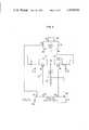
- the field coil 1lies in the one diagonal of a bridge circuit 2 comprising four switching members 3,4, 5, 6 which for simplification are illustrated as mechanical switches.
- the switching membersmay be relay contacts or also electronic switching members as will be explained hereinafter with reference to the examples of embodiment illustrated in FIGS. 3 and 4.
- a supply DC voltagewhich is furnished by a DC voltage source 7.
- the DC voltage source 7is a mains network, the input terminals 7a, 7b of which receive an AC voltage and which furnishes at its output terminals 7c, 7d a rectified voltage.
- the mains network 7also comprises a voltage control input 7e; by a control signal applied to said input the magnitude of the DC voltage delivered at the output 7c, 7d is defined.
- the output terminal 7d of the mains network 7 carrying the negative output potentialis connected to ground.
- the output terminal 7c carrying the positive potentialis connected via a current regulating transistor 8 and a diode 9 to the corner point 2a of the bridge circuit 2.
- the opposite bridge corner point 2bis connected via a current measuring resistance 10 to ground.
- the field coil 1is connected between the two other bridge corner points 2c, 2d.
- the operation outlinedis controlled by a control and regulating circuit 11.
- the lattercomprises a clock input 11a at which it receives a clock signal which is formed for example by a rectangular or square voltage which assumes alternately the values 0 and 1.
- the control and regulating circuit 11receives the voltage across the current measuring resistance 10 which is a measurement of the current flowing through the field coil 1.
- An output 11cfurnishes a control signal for simultaneous actuation of the switches 3 and 5 and a further output 11d furnishes a control signal for simultaneously actuating the switches 4 and 6.
- the control and regulating circuit 11furnishes a regulating signal for adjusting the current regulating transistor 8.
- a further output 11f of the control and regulating circuit 11is connected to the voltage control input 7e of the mains network 7.
- the control and regulating circuitis so constructed that for the one value of the clock signal applied to its clock input 11a it furnishes at the output 11c a signal which closes the connected switches 3 and 5 whilst simultaneously furnishing at the output 11d a signal which opens the connected switches 4 and 6; for the other value of the clock signal these control signals are reversed.
- a push-pull actuation of the switch pairs 3, 5 and 4, 6takes place with the rhythm defined by the clock signal.
- the signal received at the input 11bindicates to the control and regulating circuit 11 the magnitude of the current flowing through the field coil 1. It furnishes at the output 11c a control signal by which the value of said current is held in the stationary condition by the current regulating transistor 8 at a predetermined desired value.
- a capacitor 12 dimensioned in particular manneris connected between the bridge corner point 2a and ground.
- FIG. 2shows the arrangement of FIG. 1 immediately after initiation of the reversal operation, i.e. after opening of the switches 3, 5 and closing of the switches 4, 6.
- the capacitor 12Prior to the opening of the switches 3, 5 (FIG. 1) the capacitor 12 was charged to a voltage which was equal to the output voltage of the mains network 7 less the voltage drops across the current regulating transistor 8 and the diode 9.
- the field coil 1Immediately after opening of the switches 3, 5 and closing of the switches 4, 6 (FIG. 2) the field coil 1 produces a current which initially has the same direction as the current I F in the previous switch condition (FIG. 1). This current is indicated in FIG. 2 by the arrows drawn in full lines. However, it now flows from ground via the current measuring resistance 10 to the bridge corner point 2b and from the latter via the closed switch 4, the field coil 1 and the closed switch 6 to the bridge corner point 2a. The diode 9 prevents this current from being able to flow back to the mains network 7. This current must therefore be taken up by the capacitor 12 whose charge is increased so that its terminal voltage rises.
- the reversal timeis longer and on the other hand an energy loss occurs.
- the mains networkIn order to reach a current value of the same magnitude in the field coil after reversal the mains network must enter the operation.
- the resonant circuit parametersmust fulfil the following conditions:
- FIG. 3an embodiment is illustrated which differs from the embodiment of FIGS. 1 and 2 only in that the switching members 3, 4, 5, 6 which in FIGS. 1 and 2 are represented as mechanical switches (e.g. relay contacts) are formed by transistors 13, 14, 15, 16.
- the collector of the transistor 13is connected to the bridge corner point 2a and its emitter to the bridge corner point 2c.
- the collect-emitter circuits of the transistor 14are connected between the bridge corner points 2c, 2b, those of the transistor 15 between the bridge corner points 2d, 2b and those of the transistor 16 between the bridge corner points 2a, 2d.
- the bases of the transistors 13 and 15jointly receive via base resistors 13a and 15a respectively a control signal from the output 11c of the control and regulating circuit 11 and the bases of the transistors 14 and 16 receive jointly via base resistors 14a and 16a respectively a control signal from the output 11d of the control and regulating circuit 11. Since transistors, in contrast to the mechanical switches illustrated in FIGS. 1 and 2, can transmit a current only in one direction a diode 17, 18, 19, 20 of opposite forward direction is connected in parallel with the collector-emitter path of each transistor.
- the remaining components of the arrangement of FIG. 3have the same structure and the same mode of operation as the corresponding components of the arrangement of FIGS. 1 and 2 and are designated with the same reference numerals as in the latter Figures.
- the capacitance of the capacitor 12is so dimensioned in the manner previously outlined that the desired reversal time ⁇ t is achieved.
- FIG. 3has the operating condition illustrated in FIG. 1.
- a currentthen flows from the terminal 7c of the mains network 7 via the current regulating transistor 8 and the diode 9 to the bridge corner point 2a and from the latter via the conductive transistor 13 through the field coil 1 and the conductive transistor 15 to the bridge corner point 2b and from there finally via the current measuring resistance 10 to ground.
- the arrows indicated in FIG. 3correspond to the operating condition of FIG. 2, i.e. the conditions on changing from the previously outlined switch condition to the opposite switch condition, i.e. immediately after blocking of the transistors 13, 15 and opening of the transistors 14, 16.
- the field coil 1maintains a current in the same direction as before; this current is indicated in FIG. 3 by arrows drawn in full lines.
- This currentnow flows from ground via the current measuring resistance 10 to the bridge corner point 2b and from the latter via the diode 18, the field coil 1 and the diode 20 to the bridge corner point 2a. Since due to the blocking action of the diode 9 this current cannot flow back to the mains network 7 it is taken up by the capacitor 12 whose terminal voltage rises in the manner outlined previously.
- each of the transistors 13, 14, 15, 16 of FIG. 3 with the oppositely poled parallel-connected diode 17, 18, 19, 20fulfils the same function as the corresponding mechanical switch of FIGS. 1 and 2.
- the field coil 1is connected to the capacitor 12 during the reversal operation to form a resonant circuit which is separated by the diode 9 from the mains network 7.
- the field coil 21does not lie in the diagonal of a bridge circuit but in series with the current measuring resistance 22 in the cross branch of a T circuit 23 between the circuit point 24 and ground.
- the switching membersare again formed as in the case of FIG. 3 by transistors 25, 26, a diode 27 and 28 respectively being connected in parallel oppositely poled with the collector-emitter circuit of each transistor.
- This circuitrequires that the mains network 30, which again receives at the input terminals 30a, 30b an AC voltage, furnishes at its output terminals 30c and 30d two DC voltages symmetrical with respect to ground.
- the output terminal 30cwhich furnishes the voltage positive with respect to ground, is connected via a diode 31 to the collector of the transistor 25 whose emitter is connected to the circuit point 24.
- the output termnal 30d furnishing the negative voltageis connected via a diode 32 to the emitter of the transistor 26 whose collector is connected to the circuit point 24.
- each of these two capacitorshas a capacitance C which is dimensioned in the manner previously described in dependence upon the inductance L and the resistance R of the field coil 21 and the desired reversal time ⁇ t.
- the operating cycle of the circuitis controlled by a control and regulating circuit 35 which receives at its input 35a a clock signal defining the reversal rate.
- the input 35breceives the voltage drop at the current measuring resistance 22 which is a measure of the current flowing through the field coil 21.
- the base of the transistor 25is connected to an output 35c and the base of the transistor 26 to an output 35d of the control and regulating circuit 35.
- an output 35e of the control and regulating circuit 35furnishes a control signal to the voltage control input 30e of the mains network 30.
- control and regulating circuit 35is thus so constructed that it furnishes at its outputs 35c, 35d control signals which in dependence upon the signal applied to the input 35b adjust the current flowing through the respective opened transistor 25 or 26 to the desired constant value.
- This circuitoperates in the following manner:
- the control and regulating circuit 35bfurnishes at the output 35c a signal which renders the transistor 25 conductive whilst simultaneously furnishing at the output 35d a signal which renders the transistor 26 non-conductive. Accordingly, a direct current flows from the output terminal 30c of the mains network 30 via the diode 31 and the opened transistor 25 to the circuit point 24 and from there via the field coil 21 and the current measuring resistance 22 to ground. The capacitor 33 is thereby charged substantially to the positive voltage of the terminal 30c apart from the voltage drop across the diode 31.
- the transistor 25is blocked and the transistor 26 opened so that now a current flows from ground via the current measuring resistance 22 and the field coil 21 to the circuit point 24 from whence it passes via the opened transistor 26 and the diode 32 to the terminal 30d of the mains network 30.
- the capacitor 34is thereby substantially charged to the negative voltage of the terminal 30d apart from the voltage drop across the diode 32.
- the current in the field coil 21Prior to initiation of the reversal operation the current in the field coil 21 has the direction indicated by the arrow drawn in full line, i.e. from the circuit point 24 to ground. After blockage of the transistor 25 the field coil 21 at first maintains the current direction but this current must now be supplied by the capacitor 34. A current thus flows from the capacitor 34 via the diode 28 to the circuit point 24 as indicated by the arrows drawn in full lines. The negative terminal voltage of the capacitor 34 therefore increases in magnitude biasing the diode 32 in the reverse direction.
- the switching membersmay be formed by mechanical switches (e.g. relay contacts); however, in this case in each longitudinal branch of the T circuit an additional current regulating transistor must be provided.
- a further shortening of the reversal timecan be achieved in that the output voltage of the mains network is temporarily increased during the reversal operation. It is done by the control signal supplied by the output 35e of the control and regulating circuit 35 to the control input 30e of the mains network 30.
- circuit 11The structure in circuit 11 is known.
- a box 16 labelled "Main Control Circuit”performs the identical function in controlling transistors 13A and 13B, as circuit 11 of the present application does in controlling transistors 13 to 16 (FIG. 3).
- FIG. 5shows the structure in circuit 11 and FIGS. 6a-6e show the time diagrams of the signals appearing at various terminals of the circuit arrangement shown in FIGS. 1, 2 and 3.
- the arrangement for the control of the switches 3 to 6is extremely simple: terminal 11c is directly connected to input terminal 11a, so that it carries a signal which is identical with the rectangular clock signal supplied to the input 11a; if necessary, an amplifier A may be inserted in this connection.
- Terminal 11dis connected to the output of an inverter stage I, the input of which receives the clock signal, so that the output signal at terminal 11d is 180° phase shifted with respect to the output signal at terminal 11c.
- this portion of circuit 11could be readily determined by one of ordinary skill in this art without undue experimentation.
- a conventional current regulating circuitis connected between terminals 11b and 11c.
- This circuitmay comprise a differential amplifier D receiving at one input the voltage supplied to input 11b with suitable filtering and at the other input a reference voltage V REF .
- the output of differential amplifier Dcontrols the current regulating transistor 8.
- This arrangementis very similar to the current control circuit 20 shown in FIG. 4 of U.S. Pat. No. 3,733,538 and corresponds to the prior art technique mentioned in the section "Background of the Invention" in column 1, lines 10 to 21, of this patent.
- Terminal 11fis connected to the output of a monostable multivibrator M which is triggered by each positive and negative going edge of the rectangular clock signal supplied to input 11a, so that it supplies a pulse at each switching operation.
- a monostable multivibrator Mwhich is triggered by each positive and negative going edge of the rectangular clock signal supplied to input 11a, so that it supplies a pulse at each switching operation.
- Each of these pulses supplied to the control input 7e of the power supply 7temporarily increases the output voltage at terminal 7c. The duration of this voltage increase is determined by the output pulse width of the monostable multivibrator which is adjustable.
- transistorsinstead of transistors other semiconductor circuit components may be used as switching members. If they are circuit members which can only transmit the current in one direction a diode of opposite polarity must be connected in parallel with each of them. These diodes may be separate circuit elements; in the case of transistors or thyristors which are formed with substrate diodes said substrate diodes can take on this function.
- a field-free phasemay be inserted between the phases of oppositely poled magnetic field in that after the closure of the previously opened adjusting members the other adjusting members are opened only after a delay by the control and regulating circuit.
Landscapes
- Physics & Mathematics (AREA)
- Electromagnetism (AREA)
- Fluid Mechanics (AREA)
- General Physics & Mathematics (AREA)
- Electronic Switches (AREA)
- Measuring Magnetic Variables (AREA)
- Other Investigation Or Analysis Of Materials By Electrical Means (AREA)
- Magnetic Resonance Imaging Apparatus (AREA)
- Measuring Volume Flow (AREA)
- Relay Circuits (AREA)
- Rectifiers (AREA)
Abstract
Description
L/R>R·C (5)
Claims (18)
Applications Claiming Priority (2)
| Application Number | Priority Date | Filing Date | Title |
|---|---|---|---|
| DE3037305 | 1980-10-02 | ||
| DE3037305ADE3037305C2 (en) | 1980-10-02 | 1980-10-02 | Arrangement for generating constant magnetic fields of alternating polarity for magnetic-inductive flow measurement |
Related Parent Applications (1)
| Application Number | Title | Priority Date | Filing Date |
|---|---|---|---|
| US06254606Continuation-In-Part | 1981-04-16 |
Publications (1)
| Publication Number | Publication Date |
|---|---|
| US4410926Atrue US4410926A (en) | 1983-10-18 |
Family
ID=6113475
Family Applications (1)
| Application Number | Title | Priority Date | Filing Date |
|---|---|---|---|
| US06/406,061Expired - LifetimeUS4410926A (en) | 1980-10-02 | 1982-08-06 | Arrangement for generating DC magnetic fields of alternating polarity for the magnetic-inductive flow measurement |
Country Status (11)
| Country | Link |
|---|---|
| US (1) | US4410926A (en) |
| JP (1) | JPS5764910A (en) |
| BE (1) | BE890573A (en) |
| CH (1) | CH655795A5 (en) |
| DD (1) | DD201727A5 (en) |
| DE (1) | DE3037305C2 (en) |
| FR (1) | FR2491620B1 (en) |
| GB (1) | GB2084827B (en) |
| IT (1) | IT1138649B (en) |
| NL (1) | NL8104462A (en) |
| SE (1) | SE458311B (en) |
Cited By (80)
| Publication number | Priority date | Publication date | Assignee | Title |
|---|---|---|---|---|
| US4725762A (en)* | 1985-02-04 | 1988-02-16 | Zumtobel Aktiengesellschaft | Circuit supplied with direct voltage for generating voltages and/or currents with different curve form and/or different frequency and/or different polarity with at least one load |
| US4733342A (en)* | 1986-06-30 | 1988-03-22 | Siemens Aktiengesellschaft | Power supply for an inductive user, particularly a gradient coil |
| US4777576A (en)* | 1986-07-10 | 1988-10-11 | Hollandse Signaalapparaten B.V. | Energy converter with series resonant bridge and switching circuit |
| US4868504A (en)* | 1987-02-09 | 1989-09-19 | Flr, Inc. | Apparatus and method for locating metal objects and minerals in the ground with return of energy from transmitter coil to power supply |
| US4879641A (en)* | 1987-11-02 | 1989-11-07 | Sgs-Thomson Microelectronics S.R.L. | Analog multiplex for sensing the magnitude and sense of the current through a h-bridge stage utilizing a single sensing resistance |
| US4890181A (en)* | 1988-03-18 | 1989-12-26 | Siemens Aktiengesellschaft | Short-circuit protection device for an electrical machine fed by a pulse-controlled A.C. converter |
| US4920470A (en)* | 1989-05-17 | 1990-04-24 | Zirco, Inc. | Voltage inverter |
| JPH02122221A (en)* | 1988-10-31 | 1990-05-09 | Shimadzu Corp | electromagnetic flow meter |
| US5012111A (en)* | 1988-06-21 | 1991-04-30 | Mitsubishi Denki Kabushiki Kaisha | Ion beam irradiation apparatus |
| US5220467A (en)* | 1989-03-04 | 1993-06-15 | Deutsche Thomson-Brandt Gmbh | Circuit arrangement for reversing a magnetic field |
| US5222012A (en)* | 1991-01-17 | 1993-06-22 | International Business Machines Corporation | Power management circuit for a magnetic repulsion punch |
| US5350992A (en)* | 1991-09-17 | 1994-09-27 | Micro-Trak Systems, Inc. | Motor control circuit |
| US5351554A (en)* | 1991-06-08 | 1994-10-04 | Endress + Hauser Flowtec Ag | Magnetoinductive flowmeter |
| US5646353A (en)* | 1995-10-20 | 1997-07-08 | Endress + Hauser Flowtec Ag | Electromagnetic flowmeter for measuring non-newtonian fluids |
| US5994929A (en)* | 1997-04-25 | 1999-11-30 | Nec Corporation | Driver for display panel |
| EP0969268A1 (en)* | 1998-07-03 | 2000-01-05 | Endress + Hauser Flowtec AG | Method of regulating the coil current of electromagnetic flow sensors |
| US6028760A (en)* | 1996-11-07 | 2000-02-22 | Anglo American Corporation Of South Africa Limited | Resonant power converter for energizing a coil |
| US6031740A (en)* | 1998-07-03 | 2000-02-29 | Endress + Hauser Flowtec Ag | Method of regulating the coil current of electromagnetic flow sensors |
| JP3043757B2 (en) | 1998-07-03 | 2000-05-22 | エンドレス ウント ハウザー フローテック アクチエンゲゼルシャフト | Adjustment method of coil current flowing through coil assembly |
| WO2000070361A1 (en)* | 1999-05-19 | 2000-11-23 | Arthur D. Little, Inc. | Low power fluxgate circuit with current balance |
| US6252440B1 (en)* | 1997-09-22 | 2001-06-26 | Matsushita Electric Industrial Co., Ltd. | Write-driver circuit |
| EP1158279A1 (en)* | 2000-05-22 | 2001-11-28 | Endress + Hauser Flowtec AG | Current regulating circuit of a magnetic inductive flowmeter for generating a feed current for an exciter circuit |
| EP1026816A3 (en)* | 1999-02-08 | 2002-03-13 | Wagner K.G. | Polarity inversion control device |
| US6646448B2 (en) | 2000-09-27 | 2003-11-11 | Seagate Technology Llc | Data head writer coil testing |
| US6686742B2 (en)* | 2000-10-17 | 2004-02-03 | Bhc Consulting Pty Ltd | Ground mineralization rejecting metal detector (power saving) |
| DE10356009A1 (en)* | 2003-11-27 | 2005-06-30 | Krohne Meßtechnik GmbH & Co KG | Magnetically inductive volumetric flow meter operating method, involves supplying current of opposite polarities to magnetic coils so that inhomogeneous magnetic field is created between electrodes, and measuring voltage between electrodes |
| WO2006032612A1 (en) | 2004-09-22 | 2006-03-30 | Endress+Hauser Flowtec Ag | Method for testing a magnetic inductive flow meter |
| US20060227490A1 (en)* | 2005-04-12 | 2006-10-12 | Trw Automotive Gmbh | Electronic drive circuit for an impulse-controlled actor |
| US20070044570A1 (en)* | 2005-08-26 | 2007-03-01 | Helmut Brockhaus | Magnetoinductive flowmeter and method for operating a magnetoinductive flowmeter |
| DE102007015368A1 (en) | 2007-03-28 | 2008-10-02 | Endress + Hauser Flowtec Ag | Method for operating a magnetic-inductive flowmeter |
| RU2437065C2 (en)* | 2009-06-08 | 2011-12-20 | Закрытое акционерное общество "Тепловизор Пром" | Method and apparatus for cleaning measuring parts of fluid medium flow metres |
| CN102680934A (en)* | 2012-05-31 | 2012-09-19 | 株洲南车时代电气股份有限公司 | Current reversing device for current sensor tests |
| US9250348B2 (en) | 2011-12-19 | 2016-02-02 | Minelab Electronics Pty Limited | Transmit signal of a metal detector controlled by feedback loops |
| US20160038009A1 (en)* | 2013-03-14 | 2016-02-11 | Given Imaging Ltd. | Method and circuit for muting electromagnetic interference during maneuvering of a device |
| US9720055B1 (en) | 2016-01-21 | 2017-08-01 | Lockheed Martin Corporation | Magnetometer with light pipe |
| US9823381B2 (en) | 2014-03-20 | 2017-11-21 | Lockheed Martin Corporation | Mapping and monitoring of hydraulic fractures using vector magnetometers |
| US9823314B2 (en) | 2016-01-21 | 2017-11-21 | Lockheed Martin Corporation | Magnetometer with a light emitting diode |
| US9824597B2 (en) | 2015-01-28 | 2017-11-21 | Lockheed Martin Corporation | Magnetic navigation methods and systems utilizing power grid and communication network |
| US9823313B2 (en) | 2016-01-21 | 2017-11-21 | Lockheed Martin Corporation | Diamond nitrogen vacancy sensor with circuitry on diamond |
| US9829545B2 (en) | 2015-11-20 | 2017-11-28 | Lockheed Martin Corporation | Apparatus and method for hypersensitivity detection of magnetic field |
| US9835693B2 (en) | 2016-01-21 | 2017-12-05 | Lockheed Martin Corporation | Higher magnetic sensitivity through fluorescence manipulation by phonon spectrum control |
| US9845153B2 (en) | 2015-01-28 | 2017-12-19 | Lockheed Martin Corporation | In-situ power charging |
| US9853837B2 (en) | 2014-04-07 | 2017-12-26 | Lockheed Martin Corporation | High bit-rate magnetic communication |
| US9910104B2 (en) | 2015-01-23 | 2018-03-06 | Lockheed Martin Corporation | DNV magnetic field detector |
| US9910105B2 (en) | 2014-03-20 | 2018-03-06 | Lockheed Martin Corporation | DNV magnetic field detector |
| GB2540308B (en)* | 2014-04-07 | 2018-05-16 | Lockheed Corp | Energy efficient controlled magnetic field generator circuit |
| US10006973B2 (en) | 2016-01-21 | 2018-06-26 | Lockheed Martin Corporation | Magnetometer with a light emitting diode |
| US10012704B2 (en) | 2015-11-04 | 2018-07-03 | Lockheed Martin Corporation | Magnetic low-pass filter |
| US10088452B2 (en) | 2016-01-12 | 2018-10-02 | Lockheed Martin Corporation | Method for detecting defects in conductive materials based on differences in magnetic field characteristics measured along the conductive materials |
| US10088336B2 (en) | 2016-01-21 | 2018-10-02 | Lockheed Martin Corporation | Diamond nitrogen vacancy sensed ferro-fluid hydrophone |
| DE102017107417A1 (en) | 2017-04-06 | 2018-10-11 | Endress+Hauser Flowtec Ag | A method of controlling a coil current flowing in a coil arrangement and a circuit arrangement |
| US10120039B2 (en) | 2015-11-20 | 2018-11-06 | Lockheed Martin Corporation | Apparatus and method for closed loop processing for a magnetic detection system |
| US10126377B2 (en) | 2016-05-31 | 2018-11-13 | Lockheed Martin Corporation | Magneto-optical defect center magnetometer |
| US10145910B2 (en) | 2017-03-24 | 2018-12-04 | Lockheed Martin Corporation | Photodetector circuit saturation mitigation for magneto-optical high intensity pulses |
| US10168393B2 (en) | 2014-09-25 | 2019-01-01 | Lockheed Martin Corporation | Micro-vacancy center device |
| US10228429B2 (en) | 2017-03-24 | 2019-03-12 | Lockheed Martin Corporation | Apparatus and method for resonance magneto-optical defect center material pulsed mode referencing |
| US10241158B2 (en) | 2015-02-04 | 2019-03-26 | Lockheed Martin Corporation | Apparatus and method for estimating absolute axes' orientations for a magnetic detection system |
| US10274550B2 (en) | 2017-03-24 | 2019-04-30 | Lockheed Martin Corporation | High speed sequential cancellation for pulsed mode |
| US10281550B2 (en) | 2016-11-14 | 2019-05-07 | Lockheed Martin Corporation | Spin relaxometry based molecular sequencing |
| US10317279B2 (en) | 2016-05-31 | 2019-06-11 | Lockheed Martin Corporation | Optical filtration system for diamond material with nitrogen vacancy centers |
| US10333588B2 (en) | 2015-12-01 | 2019-06-25 | Lockheed Martin Corporation | Communication via a magnio |
| US10330744B2 (en) | 2017-03-24 | 2019-06-25 | Lockheed Martin Corporation | Magnetometer with a waveguide |
| US10338163B2 (en) | 2016-07-11 | 2019-07-02 | Lockheed Martin Corporation | Multi-frequency excitation schemes for high sensitivity magnetometry measurement with drift error compensation |
| US10338164B2 (en) | 2017-03-24 | 2019-07-02 | Lockheed Martin Corporation | Vacancy center material with highly efficient RF excitation |
| US10338162B2 (en) | 2016-01-21 | 2019-07-02 | Lockheed Martin Corporation | AC vector magnetic anomaly detection with diamond nitrogen vacancies |
| US10345396B2 (en) | 2016-05-31 | 2019-07-09 | Lockheed Martin Corporation | Selected volume continuous illumination magnetometer |
| US10345395B2 (en) | 2016-12-12 | 2019-07-09 | Lockheed Martin Corporation | Vector magnetometry localization of subsurface liquids |
| US10359479B2 (en) | 2017-02-20 | 2019-07-23 | Lockheed Martin Corporation | Efficient thermal drift compensation in DNV vector magnetometry |
| US10371765B2 (en) | 2016-07-11 | 2019-08-06 | Lockheed Martin Corporation | Geolocation of magnetic sources using vector magnetometer sensors |
| US10371760B2 (en) | 2017-03-24 | 2019-08-06 | Lockheed Martin Corporation | Standing-wave radio frequency exciter |
| US10379174B2 (en) | 2017-03-24 | 2019-08-13 | Lockheed Martin Corporation | Bias magnet array for magnetometer |
| US10408889B2 (en) | 2015-02-04 | 2019-09-10 | Lockheed Martin Corporation | Apparatus and method for recovery of three dimensional magnetic field from a magnetic detection system |
| US10408890B2 (en) | 2017-03-24 | 2019-09-10 | Lockheed Martin Corporation | Pulsed RF methods for optimization of CW measurements |
| US10459041B2 (en) | 2017-03-24 | 2019-10-29 | Lockheed Martin Corporation | Magnetic detection system with highly integrated diamond nitrogen vacancy sensor |
| US10466312B2 (en) | 2015-01-23 | 2019-11-05 | Lockheed Martin Corporation | Methods for detecting a magnetic field acting on a magneto-optical detect center having pulsed excitation |
| US10520558B2 (en) | 2016-01-21 | 2019-12-31 | Lockheed Martin Corporation | Diamond nitrogen vacancy sensor with nitrogen-vacancy center diamond located between dual RF sources |
| US10527746B2 (en) | 2016-05-31 | 2020-01-07 | Lockheed Martin Corporation | Array of UAVS with magnetometers |
| US10571530B2 (en) | 2016-05-31 | 2020-02-25 | Lockheed Martin Corporation | Buoy array of magnetometers |
| US10677953B2 (en) | 2016-05-31 | 2020-06-09 | Lockheed Martin Corporation | Magneto-optical detecting apparatus and methods |
| WO2024133392A1 (en)* | 2022-12-21 | 2024-06-27 | Endress+Hauser Flowtec Ag | Device for providing an excitation current at a magnetic-inductive flowmeter, and magnetic-inductive flowmeter |
Families Citing this family (19)
| Publication number | Priority date | Publication date | Assignee | Title |
|---|---|---|---|---|
| DE3334152A1 (en)* | 1983-09-21 | 1985-04-04 | Fischer & Porter GmbH, 3400 Göttingen | MAGNETICALLY INDUCTIVE FLOW METER |
| DE3442272A1 (en)* | 1984-11-20 | 1986-05-22 | Turbo-Werk Messtechnik GmbH, 5000 Köln | Inductive flowmeter |
| DE3512921A1 (en)* | 1985-04-11 | 1986-10-16 | Turbo-Werk Messtechnik GmbH, 5000 Köln | Circuit arrangement for producing a pulsating magnetic field in the exciter coil of an inductive flowmeter |
| GB8530930D0 (en)* | 1985-12-16 | 1986-01-29 | Mansfield P | Inductive circuit arrangements |
| DE3616407A1 (en)* | 1986-05-15 | 1987-11-19 | Bopp & Reuther Gmbh | Inductive flowmeter |
| NL8601331A (en)* | 1986-05-26 | 1987-12-16 | At & T & Philips Telecomm | TRANSMITTER FOR ISDN S-BUS COUPLING CIRCUIT. |
| US4916381A (en)* | 1988-05-12 | 1990-04-10 | Rosemount Inc. | Current source for a variable load with an inductive component |
| GB0200027D0 (en) | 2002-01-02 | 2002-02-13 | Bae Systems Plc | Improvements relating to operation of a current controller |
| GB0200024D0 (en) | 2002-01-02 | 2002-02-13 | Bae Systems Plc | A switching circuit and a method of operation thereof |
| GB0200030D0 (en) | 2002-01-02 | 2002-02-13 | Bae Systems Plc | A switching circuit and a method of operation thereof |
| JP4761219B2 (en)* | 2007-03-27 | 2011-08-31 | 独立行政法人情報通信研究機構 | Horizontal plane beam scanning antenna |
| DE102011087827A1 (en)* | 2011-12-06 | 2013-06-06 | Endress + Hauser Flowtec Ag | Method and circuit for network synchronization of a magnetic-inductive flowmeter |
| JP5843670B2 (en)* | 2012-03-15 | 2016-01-13 | アズビル株式会社 | Excitation circuit of electromagnetic flow meter |
| JP2014128175A (en)* | 2012-12-27 | 2014-07-07 | Nidec Sankyo Corp | Magnetic field generation device, and magnetic recording medium processing device |
| DE102016110024A1 (en) | 2016-05-31 | 2017-11-30 | Endress + Hauser Flowtec Ag | Method for operating an electromagnetic flowmeter for measuring the flow rate or the volume flow of a medium in a measuring tube |
| JP6999300B2 (en)* | 2017-06-30 | 2022-01-18 | 日本電産サンキョー株式会社 | Magnetic recording medium processing device and interference magnetic field generation method |
| US20200309578A1 (en)* | 2017-07-07 | 2020-10-01 | Apator Miitors Aps | Electromagnetic flow meter |
| EP3460419B1 (en)* | 2017-09-22 | 2020-04-01 | VEGA Grieshaber KG | Measurement assembly, measuring device with a measurement assembly and method for operating the measurement device |
| CN112327225B (en)* | 2020-11-05 | 2024-08-09 | 郑州轻工业大学 | Method for detecting magnetic field based on magneto-dielectric effect, test device and working method thereof |
Citations (4)
| Publication number | Priority date | Publication date | Assignee | Title |
|---|---|---|---|---|
| US3284692A (en)* | 1963-06-05 | 1966-11-08 | Lambda Electronics Corp | Compensated regulated power supply |
| US3733538A (en)* | 1972-03-28 | 1973-05-15 | Westinghouse Electric Corp | Apparatus for limiting instantaneous inverter current |
| US3893006A (en)* | 1974-01-14 | 1975-07-01 | Nordson Corp | High voltage power supply with overcurrent protection |
| DE2744845A1 (en)* | 1977-10-05 | 1979-04-19 | Flowtec Ag | METHOD AND DEVICE FOR INDUCTIVE FLOW MEASUREMENT |
Family Cites Families (4)
| Publication number | Priority date | Publication date | Assignee | Title |
|---|---|---|---|---|
| US3684983A (en)* | 1970-06-19 | 1972-08-15 | E & M Lab | High speed circulator switch |
| US3896346A (en)* | 1972-11-21 | 1975-07-22 | Electronic Camshaft Corp | High speed electromagnet control circuit |
| US3955413A (en)* | 1974-03-27 | 1976-05-11 | Steele James R | Electrical system for electromagnetically measuring flow of fluid |
| DE2934990C2 (en)* | 1979-08-30 | 1985-04-18 | Eckardt Ag, 7000 Stuttgart | Arrangement for magnetic flow measurement |
- 1980
- 1980-10-02DEDE3037305Apatent/DE3037305C2/ennot_activeExpired
- 1981
- 1981-04-15JPJP56055732Apatent/JPS5764910A/enactiveGranted
- 1981-08-26GBGB8126061Apatent/GB2084827B/ennot_activeExpired
- 1981-09-28ITIT24179/81Apatent/IT1138649B/enactive
- 1981-09-30DDDD81233719Apatent/DD201727A5/enunknown
- 1981-09-30FRFR8118394Apatent/FR2491620B1/ennot_activeExpired
- 1981-09-30NLNL8104462Apatent/NL8104462A/ennot_activeApplication Discontinuation
- 1981-10-01CHCH6316/81Apatent/CH655795A5/ennot_activeIP Right Cessation
- 1981-10-01BEBE2/59391Apatent/BE890573A/ennot_activeIP Right Cessation
- 1981-10-01SESE8105807Apatent/SE458311B/ennot_activeIP Right Cessation
- 1982
- 1982-08-06USUS06/406,061patent/US4410926A/ennot_activeExpired - Lifetime
Patent Citations (4)
| Publication number | Priority date | Publication date | Assignee | Title |
|---|---|---|---|---|
| US3284692A (en)* | 1963-06-05 | 1966-11-08 | Lambda Electronics Corp | Compensated regulated power supply |
| US3733538A (en)* | 1972-03-28 | 1973-05-15 | Westinghouse Electric Corp | Apparatus for limiting instantaneous inverter current |
| US3893006A (en)* | 1974-01-14 | 1975-07-01 | Nordson Corp | High voltage power supply with overcurrent protection |
| DE2744845A1 (en)* | 1977-10-05 | 1979-04-19 | Flowtec Ag | METHOD AND DEVICE FOR INDUCTIVE FLOW MEASUREMENT |
Cited By (91)
| Publication number | Priority date | Publication date | Assignee | Title |
|---|---|---|---|---|
| US4725762A (en)* | 1985-02-04 | 1988-02-16 | Zumtobel Aktiengesellschaft | Circuit supplied with direct voltage for generating voltages and/or currents with different curve form and/or different frequency and/or different polarity with at least one load |
| US4733342A (en)* | 1986-06-30 | 1988-03-22 | Siemens Aktiengesellschaft | Power supply for an inductive user, particularly a gradient coil |
| US4777576A (en)* | 1986-07-10 | 1988-10-11 | Hollandse Signaalapparaten B.V. | Energy converter with series resonant bridge and switching circuit |
| US4868504A (en)* | 1987-02-09 | 1989-09-19 | Flr, Inc. | Apparatus and method for locating metal objects and minerals in the ground with return of energy from transmitter coil to power supply |
| US4879641A (en)* | 1987-11-02 | 1989-11-07 | Sgs-Thomson Microelectronics S.R.L. | Analog multiplex for sensing the magnitude and sense of the current through a h-bridge stage utilizing a single sensing resistance |
| US4890181A (en)* | 1988-03-18 | 1989-12-26 | Siemens Aktiengesellschaft | Short-circuit protection device for an electrical machine fed by a pulse-controlled A.C. converter |
| US5012111A (en)* | 1988-06-21 | 1991-04-30 | Mitsubishi Denki Kabushiki Kaisha | Ion beam irradiation apparatus |
| JPH02122221A (en)* | 1988-10-31 | 1990-05-09 | Shimadzu Corp | electromagnetic flow meter |
| US5220467A (en)* | 1989-03-04 | 1993-06-15 | Deutsche Thomson-Brandt Gmbh | Circuit arrangement for reversing a magnetic field |
| US4920470A (en)* | 1989-05-17 | 1990-04-24 | Zirco, Inc. | Voltage inverter |
| US5222012A (en)* | 1991-01-17 | 1993-06-22 | International Business Machines Corporation | Power management circuit for a magnetic repulsion punch |
| US5351554A (en)* | 1991-06-08 | 1994-10-04 | Endress + Hauser Flowtec Ag | Magnetoinductive flowmeter |
| US5350992A (en)* | 1991-09-17 | 1994-09-27 | Micro-Trak Systems, Inc. | Motor control circuit |
| US5646353A (en)* | 1995-10-20 | 1997-07-08 | Endress + Hauser Flowtec Ag | Electromagnetic flowmeter for measuring non-newtonian fluids |
| US6028760A (en)* | 1996-11-07 | 2000-02-22 | Anglo American Corporation Of South Africa Limited | Resonant power converter for energizing a coil |
| RU2216094C2 (en)* | 1996-11-07 | 2003-11-10 | Англо Американ Корпорейшн Оф Саут Африка Лимитед | Resonance-tuned power converter for coil excitation |
| US5994929A (en)* | 1997-04-25 | 1999-11-30 | Nec Corporation | Driver for display panel |
| US6252440B1 (en)* | 1997-09-22 | 2001-06-26 | Matsushita Electric Industrial Co., Ltd. | Write-driver circuit |
| US6031740A (en)* | 1998-07-03 | 2000-02-29 | Endress + Hauser Flowtec Ag | Method of regulating the coil current of electromagnetic flow sensors |
| JP3043757B2 (en) | 1998-07-03 | 2000-05-22 | エンドレス ウント ハウザー フローテック アクチエンゲゼルシャフト | Adjustment method of coil current flowing through coil assembly |
| CN1096604C (en)* | 1998-07-03 | 2002-12-18 | 安德雷斯和霍瑟·弗罗泰克有限公司 | Method of regulating coil current of electromagnetic flow sensors |
| EP0969268A1 (en)* | 1998-07-03 | 2000-01-05 | Endress + Hauser Flowtec AG | Method of regulating the coil current of electromagnetic flow sensors |
| EP1026816A3 (en)* | 1999-02-08 | 2002-03-13 | Wagner K.G. | Polarity inversion control device |
| WO2000070361A1 (en)* | 1999-05-19 | 2000-11-23 | Arthur D. Little, Inc. | Low power fluxgate circuit with current balance |
| US6218831B1 (en)* | 1999-05-19 | 2001-04-17 | Arthur D. Little, Inc. | Low power fluxgate circuit with current balance |
| EP1158279A1 (en)* | 2000-05-22 | 2001-11-28 | Endress + Hauser Flowtec AG | Current regulating circuit of a magnetic inductive flowmeter for generating a feed current for an exciter circuit |
| US6477070B2 (en) | 2000-05-22 | 2002-11-05 | Endress + Hauser Flowtec Ag | Current-regulator circuit of an electromagnetic flowmeter |
| US6646448B2 (en) | 2000-09-27 | 2003-11-11 | Seagate Technology Llc | Data head writer coil testing |
| US6686742B2 (en)* | 2000-10-17 | 2004-02-03 | Bhc Consulting Pty Ltd | Ground mineralization rejecting metal detector (power saving) |
| DE10356009A1 (en)* | 2003-11-27 | 2005-06-30 | Krohne Meßtechnik GmbH & Co KG | Magnetically inductive volumetric flow meter operating method, involves supplying current of opposite polarities to magnetic coils so that inhomogeneous magnetic field is created between electrodes, and measuring voltage between electrodes |
| DE10356009B4 (en)* | 2003-11-27 | 2007-10-18 | Krohne Meßtechnik GmbH & Co KG | Magnetic-inductive flowmeter and method for operating a magnetic-inductive flowmeter |
| WO2006032612A1 (en) | 2004-09-22 | 2006-03-30 | Endress+Hauser Flowtec Ag | Method for testing a magnetic inductive flow meter |
| US20060227490A1 (en)* | 2005-04-12 | 2006-10-12 | Trw Automotive Gmbh | Electronic drive circuit for an impulse-controlled actor |
| US20070044570A1 (en)* | 2005-08-26 | 2007-03-01 | Helmut Brockhaus | Magnetoinductive flowmeter and method for operating a magnetoinductive flowmeter |
| US7194918B2 (en) | 2005-08-26 | 2007-03-27 | Krohne Messtechnik Gmbh & Co. Kg | Magnetoinductive flowmeter and method for operating a magnetoinductive flowmeter |
| DE102007015368A1 (en) | 2007-03-28 | 2008-10-02 | Endress + Hauser Flowtec Ag | Method for operating a magnetic-inductive flowmeter |
| RU2437065C2 (en)* | 2009-06-08 | 2011-12-20 | Закрытое акционерное общество "Тепловизор Пром" | Method and apparatus for cleaning measuring parts of fluid medium flow metres |
| US9250348B2 (en) | 2011-12-19 | 2016-02-02 | Minelab Electronics Pty Limited | Transmit signal of a metal detector controlled by feedback loops |
| CN102680934A (en)* | 2012-05-31 | 2012-09-19 | 株洲南车时代电气股份有限公司 | Current reversing device for current sensor tests |
| US20160038009A1 (en)* | 2013-03-14 | 2016-02-11 | Given Imaging Ltd. | Method and circuit for muting electromagnetic interference during maneuvering of a device |
| US10357144B2 (en)* | 2013-03-14 | 2019-07-23 | Given Imaging Ltd. | Method and circuit for muting electromagnetic interference during maneuvering of a device |
| US10725124B2 (en) | 2014-03-20 | 2020-07-28 | Lockheed Martin Corporation | DNV magnetic field detector |
| US9910105B2 (en) | 2014-03-20 | 2018-03-06 | Lockheed Martin Corporation | DNV magnetic field detector |
| US9823381B2 (en) | 2014-03-20 | 2017-11-21 | Lockheed Martin Corporation | Mapping and monitoring of hydraulic fractures using vector magnetometers |
| US9853837B2 (en) | 2014-04-07 | 2017-12-26 | Lockheed Martin Corporation | High bit-rate magnetic communication |
| GB2540308B (en)* | 2014-04-07 | 2018-05-16 | Lockheed Corp | Energy efficient controlled magnetic field generator circuit |
| US10277208B2 (en) | 2014-04-07 | 2019-04-30 | Lockheed Martin Corporation | Energy efficient controlled magnetic field generator circuit |
| US10168393B2 (en) | 2014-09-25 | 2019-01-01 | Lockheed Martin Corporation | Micro-vacancy center device |
| US9910104B2 (en) | 2015-01-23 | 2018-03-06 | Lockheed Martin Corporation | DNV magnetic field detector |
| US10466312B2 (en) | 2015-01-23 | 2019-11-05 | Lockheed Martin Corporation | Methods for detecting a magnetic field acting on a magneto-optical detect center having pulsed excitation |
| US9845153B2 (en) | 2015-01-28 | 2017-12-19 | Lockheed Martin Corporation | In-situ power charging |
| US9824597B2 (en) | 2015-01-28 | 2017-11-21 | Lockheed Martin Corporation | Magnetic navigation methods and systems utilizing power grid and communication network |
| US10408889B2 (en) | 2015-02-04 | 2019-09-10 | Lockheed Martin Corporation | Apparatus and method for recovery of three dimensional magnetic field from a magnetic detection system |
| US10241158B2 (en) | 2015-02-04 | 2019-03-26 | Lockheed Martin Corporation | Apparatus and method for estimating absolute axes' orientations for a magnetic detection system |
| US10012704B2 (en) | 2015-11-04 | 2018-07-03 | Lockheed Martin Corporation | Magnetic low-pass filter |
| US10120039B2 (en) | 2015-11-20 | 2018-11-06 | Lockheed Martin Corporation | Apparatus and method for closed loop processing for a magnetic detection system |
| US9829545B2 (en) | 2015-11-20 | 2017-11-28 | Lockheed Martin Corporation | Apparatus and method for hypersensitivity detection of magnetic field |
| US10333588B2 (en) | 2015-12-01 | 2019-06-25 | Lockheed Martin Corporation | Communication via a magnio |
| US10088452B2 (en) | 2016-01-12 | 2018-10-02 | Lockheed Martin Corporation | Method for detecting defects in conductive materials based on differences in magnetic field characteristics measured along the conductive materials |
| US9823314B2 (en) | 2016-01-21 | 2017-11-21 | Lockheed Martin Corporation | Magnetometer with a light emitting diode |
| US9835694B2 (en) | 2016-01-21 | 2017-12-05 | Lockheed Martin Corporation | Higher magnetic sensitivity through fluorescence manipulation by phonon spectrum control |
| US9720055B1 (en) | 2016-01-21 | 2017-08-01 | Lockheed Martin Corporation | Magnetometer with light pipe |
| US10520558B2 (en) | 2016-01-21 | 2019-12-31 | Lockheed Martin Corporation | Diamond nitrogen vacancy sensor with nitrogen-vacancy center diamond located between dual RF sources |
| US9817081B2 (en) | 2016-01-21 | 2017-11-14 | Lockheed Martin Corporation | Magnetometer with light pipe |
| US10088336B2 (en) | 2016-01-21 | 2018-10-02 | Lockheed Martin Corporation | Diamond nitrogen vacancy sensed ferro-fluid hydrophone |
| US10006973B2 (en) | 2016-01-21 | 2018-06-26 | Lockheed Martin Corporation | Magnetometer with a light emitting diode |
| US9823313B2 (en) | 2016-01-21 | 2017-11-21 | Lockheed Martin Corporation | Diamond nitrogen vacancy sensor with circuitry on diamond |
| US9835693B2 (en) | 2016-01-21 | 2017-12-05 | Lockheed Martin Corporation | Higher magnetic sensitivity through fluorescence manipulation by phonon spectrum control |
| US10338162B2 (en) | 2016-01-21 | 2019-07-02 | Lockheed Martin Corporation | AC vector magnetic anomaly detection with diamond nitrogen vacancies |
| US10345396B2 (en) | 2016-05-31 | 2019-07-09 | Lockheed Martin Corporation | Selected volume continuous illumination magnetometer |
| US10527746B2 (en) | 2016-05-31 | 2020-01-07 | Lockheed Martin Corporation | Array of UAVS with magnetometers |
| US10677953B2 (en) | 2016-05-31 | 2020-06-09 | Lockheed Martin Corporation | Magneto-optical detecting apparatus and methods |
| US10317279B2 (en) | 2016-05-31 | 2019-06-11 | Lockheed Martin Corporation | Optical filtration system for diamond material with nitrogen vacancy centers |
| US10126377B2 (en) | 2016-05-31 | 2018-11-13 | Lockheed Martin Corporation | Magneto-optical defect center magnetometer |
| US10571530B2 (en) | 2016-05-31 | 2020-02-25 | Lockheed Martin Corporation | Buoy array of magnetometers |
| US10338163B2 (en) | 2016-07-11 | 2019-07-02 | Lockheed Martin Corporation | Multi-frequency excitation schemes for high sensitivity magnetometry measurement with drift error compensation |
| US10371765B2 (en) | 2016-07-11 | 2019-08-06 | Lockheed Martin Corporation | Geolocation of magnetic sources using vector magnetometer sensors |
| US10281550B2 (en) | 2016-11-14 | 2019-05-07 | Lockheed Martin Corporation | Spin relaxometry based molecular sequencing |
| US10345395B2 (en) | 2016-12-12 | 2019-07-09 | Lockheed Martin Corporation | Vector magnetometry localization of subsurface liquids |
| US10359479B2 (en) | 2017-02-20 | 2019-07-23 | Lockheed Martin Corporation | Efficient thermal drift compensation in DNV vector magnetometry |
| US10379174B2 (en) | 2017-03-24 | 2019-08-13 | Lockheed Martin Corporation | Bias magnet array for magnetometer |
| US10274550B2 (en) | 2017-03-24 | 2019-04-30 | Lockheed Martin Corporation | High speed sequential cancellation for pulsed mode |
| US10408890B2 (en) | 2017-03-24 | 2019-09-10 | Lockheed Martin Corporation | Pulsed RF methods for optimization of CW measurements |
| US10459041B2 (en) | 2017-03-24 | 2019-10-29 | Lockheed Martin Corporation | Magnetic detection system with highly integrated diamond nitrogen vacancy sensor |
| US10228429B2 (en) | 2017-03-24 | 2019-03-12 | Lockheed Martin Corporation | Apparatus and method for resonance magneto-optical defect center material pulsed mode referencing |
| US10330744B2 (en) | 2017-03-24 | 2019-06-25 | Lockheed Martin Corporation | Magnetometer with a waveguide |
| US10371760B2 (en) | 2017-03-24 | 2019-08-06 | Lockheed Martin Corporation | Standing-wave radio frequency exciter |
| US10338164B2 (en) | 2017-03-24 | 2019-07-02 | Lockheed Martin Corporation | Vacancy center material with highly efficient RF excitation |
| US10145910B2 (en) | 2017-03-24 | 2018-12-04 | Lockheed Martin Corporation | Photodetector circuit saturation mitigation for magneto-optical high intensity pulses |
| DE102017107417A1 (en) | 2017-04-06 | 2018-10-11 | Endress+Hauser Flowtec Ag | A method of controlling a coil current flowing in a coil arrangement and a circuit arrangement |
| WO2024133392A1 (en)* | 2022-12-21 | 2024-06-27 | Endress+Hauser Flowtec Ag | Device for providing an excitation current at a magnetic-inductive flowmeter, and magnetic-inductive flowmeter |
Also Published As
| Publication number | Publication date |
|---|---|
| DE3037305A1 (en) | 1982-06-24 |
| JPS5764910A (en) | 1982-04-20 |
| SE458311B (en) | 1989-03-13 |
| SE8105807L (en) | 1982-04-03 |
| GB2084827B (en) | 1984-09-05 |
| CH655795A5 (en) | 1986-05-15 |
| IT1138649B (en) | 1986-09-17 |
| GB2084827A (en) | 1982-04-15 |
| FR2491620A1 (en) | 1982-04-09 |
| JPS6325691B2 (en) | 1988-05-26 |
| IT8124179A0 (en) | 1981-09-28 |
| FR2491620B1 (en) | 1986-05-30 |
| DD201727A5 (en) | 1983-08-03 |
| DE3037305C2 (en) | 1986-04-03 |
| BE890573A (en) | 1982-02-01 |
| NL8104462A (en) | 1982-05-03 |
Similar Documents
| Publication | Publication Date | Title |
|---|---|---|
| US4410926A (en) | Arrangement for generating DC magnetic fields of alternating polarity for the magnetic-inductive flow measurement | |
| US8441290B2 (en) | Method and apparatus for simplifying the control of a switch | |
| US4980812A (en) | Uninterrupted power supply system having improved power factor correction circuit | |
| US3432737A (en) | Regulated direct current supply circuit with energy return path | |
| EP0534013B1 (en) | Low-loss resonant circuit for capacitance driver | |
| US5977753A (en) | Buck regulator with plural outputs | |
| US3327202A (en) | Regulated d.c. power supply system | |
| US3559029A (en) | Control circuit for regulating a dc-to-dc converter | |
| US3958131A (en) | Solid state power control apparatus | |
| US4447764A (en) | Power supply for low-voltage incandescent lamp and like load | |
| US4302802A (en) | Flyback power supply regulator | |
| JPS6348207B2 (en) | ||
| US3324378A (en) | Switching type regulated output voltage power supply | |
| US3982170A (en) | Variable speed, constant frequency induction generator system | |
| US4600982A (en) | Low power consuming AC to DC converter | |
| US3210638A (en) | Inverters and converters | |
| US6400588B1 (en) | Non-isolated A.C./D.C. converter | |
| US3932800A (en) | Direct current power control circuit | |
| US3441831A (en) | Dc to ac converter | |
| SU997204A1 (en) | Converter of dc voltage to single-phase ac voltage with amplitude-pulse modulation | |
| GB2117143A (en) | Apparatus for supplying a regulated d.c. voltage | |
| SU1432684A1 (en) | Arrangement for switching rectifiers of transformer-gate converter | |
| EP1030541B1 (en) | Power supply device for a resonant load | |
| SU653699A1 (en) | Thyristorized-magnetic frequency doubler | |
| JPH0584847B2 (en) |
Legal Events
| Date | Code | Title | Description |
|---|---|---|---|
| AS | Assignment | Owner name:FLOWTEC AG; KAGENSTRASSE 4, CH-4153 REINACH BL 1/S Free format text:ASSIGNMENT OF ASSIGNORS INTEREST.;ASSIGNORS:HAFNER, PETER;FLECKEN, PETER;REEL/FRAME:004098/0021 Effective date:19830210 | |
| STCF | Information on status: patent grant | Free format text:PATENTED CASE | |
| MAFP | Maintenance fee payment | Free format text:PAYMENT OF MAINTENANCE FEE, 4TH YEAR, PL 96-517 (ORIGINAL EVENT CODE: M170); ENTITY STATUS OF PATENT OWNER: LARGE ENTITY Year of fee payment:4 | |
| MAFP | Maintenance fee payment | Free format text:PAYMENT OF MAINTENANCE FEE, 8TH YEAR, PL 96-517 (ORIGINAL EVENT CODE: M171); ENTITY STATUS OF PATENT OWNER: LARGE ENTITY Year of fee payment:8 | |
| FEPP | Fee payment procedure | Free format text:PAYOR NUMBER ASSIGNED (ORIGINAL EVENT CODE: ASPN); ENTITY STATUS OF PATENT OWNER: LARGE ENTITY | |
| AS | Assignment | Owner name:ENDRESS + HAUSER FLOWTEC AG A SWISS CORPORATION Free format text:CHANGE OF NAME;ASSIGNOR:FLOWTEC AG, A SWISS CORP.;REEL/FRAME:006236/0842 Effective date:19911122 | |
| MAFP | Maintenance fee payment | Free format text:PAYMENT OF MAINTENANCE FEE, 12TH YEAR, LARGE ENTITY (ORIGINAL EVENT CODE: M185); ENTITY STATUS OF PATENT OWNER: LARGE ENTITY Year of fee payment:12 |