US4409993A - Endoscope apparatus - Google Patents
Endoscope apparatusDownload PDFInfo
- Publication number
- US4409993A US4409993AUS06/283,520US28352081AUS4409993AUS 4409993 AUS4409993 AUS 4409993AUS 28352081 AUS28352081 AUS 28352081AUS 4409993 AUS4409993 AUS 4409993A
- Authority
- US
- United States
- Prior art keywords
- microwave
- endoscope
- irradiator
- tip member
- passage
- Prior art date
- Legal status (The legal status is an assumption and is not a legal conclusion. Google has not performed a legal analysis and makes no representation as to the accuracy of the status listed.)
- Expired - Lifetime
Links
- 238000003780insertionMethods0.000claimsdescription24
- 230000037431insertionEffects0.000claimsdescription24
- 239000002184metalSubstances0.000claimsdescription21
- 230000002093peripheral effectEffects0.000claimsdescription11
- 239000000463materialSubstances0.000claimsdescription8
- 230000001681protective effectEffects0.000claimsdescription7
- 230000005540biological transmissionEffects0.000claimsdescription4
- 239000011347resinSubstances0.000claimsdescription4
- 229920005989resinPolymers0.000claimsdescription4
- 238000010438heat treatmentMethods0.000claimsdescription3
- 229910010293ceramic materialInorganic materials0.000claims3
- 230000001678irradiating effectEffects0.000claims2
- 206010028980NeoplasmDiseases0.000abstractdescription40
- 230000005855radiationEffects0.000abstractdescription3
- XLYOFNOQVPJJNP-UHFFFAOYSA-NwaterSubstancesOXLYOFNOQVPJJNP-UHFFFAOYSA-N0.000description5
- 238000005286illuminationMethods0.000description4
- UJKPHYRXOLRVJJ-MLSVHJFASA-NCC(O)C1=C(C)/C2=C/C3=N/C(=C\C4=C(CCC(O)=O)C(C)=C(N4)/C=C4\N=C(\C=C\1/N\2)C(C)=C4C(C)O)/C(CCC(O)=O)=C3CChemical classCC(O)C1=C(C)/C2=C/C3=N/C(=C\C4=C(CCC(O)=O)C(C)=C(N4)/C=C4\N=C(\C=C\1/N\2)C(C)=C4C(C)O)/C(CCC(O)=O)=C3CUJKPHYRXOLRVJJ-MLSVHJFASA-N0.000description3
- 230000000694effectsEffects0.000description3
- 238000009413insulationMethods0.000description3
- 239000007788liquidSubstances0.000description3
- 239000012466permeateSubstances0.000description3
- 239000003795chemical substances by applicationSubstances0.000description2
- -1for exampleSubstances0.000description2
- 238000000034methodMethods0.000description2
- 230000003287optical effectEffects0.000description2
- 230000010355oscillationEffects0.000description2
- 230000008569processEffects0.000description2
- 230000002411adverseEffects0.000description1
- 230000017531blood circulationEffects0.000description1
- 239000000919ceramicSubstances0.000description1
- 230000008859changeEffects0.000description1
- 230000006835compressionEffects0.000description1
- 238000007906compressionMethods0.000description1
- 238000001816coolingMethods0.000description1
- 230000003247decreasing effectEffects0.000description1
- 238000010292electrical insulationMethods0.000description1
- 210000004051gastric juiceAnatomy0.000description1
- 229960003569hematoporphyrinDrugs0.000description1
- 239000011796hollow space materialSubstances0.000description1
- 230000004941influxEffects0.000description1
- 238000005259measurementMethods0.000description1
- 238000012986modificationMethods0.000description1
- 230000004048modificationEffects0.000description1
- 239000013307optical fiberSubstances0.000description1
- 230000035699permeabilityEffects0.000description1
- 229920000915polyvinyl chloridePolymers0.000description1
- 239000004800polyvinyl chlorideSubstances0.000description1
- 230000000717retained effectEffects0.000description1
- 229910001220stainless steelInorganic materials0.000description1
- 239000010935stainless steelSubstances0.000description1
- 238000007669thermal treatmentMethods0.000description1
Images

Classifications
- A—HUMAN NECESSITIES
- A61—MEDICAL OR VETERINARY SCIENCE; HYGIENE
- A61B—DIAGNOSIS; SURGERY; IDENTIFICATION
- A61B18/00—Surgical instruments, devices or methods for transferring non-mechanical forms of energy to or from the body
- A61B18/18—Surgical instruments, devices or methods for transferring non-mechanical forms of energy to or from the body by applying electromagnetic radiation, e.g. microwaves
- A61B18/1815—Surgical instruments, devices or methods for transferring non-mechanical forms of energy to or from the body by applying electromagnetic radiation, e.g. microwaves using microwaves
- A—HUMAN NECESSITIES
- A61—MEDICAL OR VETERINARY SCIENCE; HYGIENE
- A61B—DIAGNOSIS; SURGERY; IDENTIFICATION
- A61B1/00—Instruments for performing medical examinations of the interior of cavities or tubes of the body by visual or photographical inspection, e.g. endoscopes; Illuminating arrangements therefor
- A61B1/00163—Optical arrangements
- A61B1/00165—Optical arrangements with light-conductive means, e.g. fibre optics
- A—HUMAN NECESSITIES
- A61—MEDICAL OR VETERINARY SCIENCE; HYGIENE
- A61B—DIAGNOSIS; SURGERY; IDENTIFICATION
- A61B17/00—Surgical instruments, devices or methods
- A61B17/32—Surgical cutting instruments
- A61B17/320016—Endoscopic cutting instruments, e.g. arthroscopes, resectoscopes
- A—HUMAN NECESSITIES
- A61—MEDICAL OR VETERINARY SCIENCE; HYGIENE
- A61B—DIAGNOSIS; SURGERY; IDENTIFICATION
- A61B18/00—Surgical instruments, devices or methods for transferring non-mechanical forms of energy to or from the body
- A61B18/18—Surgical instruments, devices or methods for transferring non-mechanical forms of energy to or from the body by applying electromagnetic radiation, e.g. microwaves
Definitions
- This inventionrelates to an endoscope apparatus which is provided with a microwave irradiator to treat an affected coeliac tissue of a living body such as a cancerous tumor by emitting microwaves to the affected portion.
- a known effective medical treatment of a tumor grown in a living bodyis based on thermal extermination.
- a conventional endoscope apparatusapplying this medical treatment process, hot air or water is ejected on a tumor from an outlet port provided at the distal end portion of the endoscope.
- the tumorperishes.
- the hot air or wateris recovered into the endoscope body through an inlet also formed at the distal end portion of the endoscope.
- the conventional endoscope arranged as described aboveenables the tumor to be medically treated with good effect.
- a normal living tissueis maintained at a prescribed coeliac temperature by a self-adjusting system, that is, blood circulation through the tissue.
- a tumorhappens to be grown under the normal tissue, then the hot air or water can not reach the interior of the living tissue where the tumor is produced, resulting in the failure to effectively treat a tumor in a living tissue due to the fact that proper heating of the tumor is not possible.
- an endoscope type high frequency knife or endoscope type laser knifeto thermally excise an affected, for example, tumor-contaminated tissue.
- these devicesare originally developed to surgically excise the affected coeliac portion of a living body, and generally irradiate extremely high energy. Where, therefore, the high frequency or laser output is irradiated on a normal tissue by mistake, then the danger arises of unnecessarily damaging or exterminating a normal tissue. Consequently, the endoscope type high frequency knife or laser knife is not practically applicable for thermal medical treatment of an affected portion of a deep coeliac section.
- this inventionprovides an endoscope apparatus which comprises an endoscope provided with a control section and insertion section drawn into a coeliac cavity, microwave-transmitting means one of whose ends is coupled to a microwave-generating device and which extends through the control section and insertion section of the endoscope and transmits microwaves generated from the microwave-generating device, and microwave-irradiating means for emitting microwaves delivered from the microwave-transmitting means in a prescribed direction.
- the microwave-irradiating meansis coupled to the other end of the microwave-transmitting means, and provided in the insertion section of the endoscope.
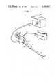
- FIG. 1is a schematic oblique view of an endoscope apparatus according to a first embodiment of this invention
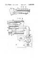
- FIG. 2is an enlarged view of the distal end portion of the endoscope apparatus of FIG. 1, also showing the arrangement of a microwave generating device attached to the endoscope apparatus;
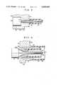
- FIG. 3is an enlarged sectional view of part of the distal end portion of an endoscope apparatus according to a second embodiment of the invention.
- FIG. 4is an enlarged sectional view of part of the distal end portion of an endoscope apparatus according to a third embodiment of the invention.
- FIG. 5indicates the sheath and microwave-irradiating device of an endoscope apparatus according to a fourth embodiment of the invention.
- FIG. 6is an enlarged sectional view of the distal end portion of an endoscope apparatus according to a fifth embodiment of the invention, also showing the arrangement of part of a light source device attached to the endoscope apparatus.
- FIGS. 1 and 2illustrate an endoscope apparatus according to a first embodiment of this invention.
- an endoscope apparatus 10includes a control section 12 and insertion section 14 insertible into a coeliac cavity of a living body.
- An eyepiece 18is fitted to an operation section 16 of the control section 12.
- a universal cord 20extends outward from the operation section 16.
- the terminal end of the universal cord 20is fitted with a connector 22.
- the connector 22is detachably fitted to a socket 24 of a light source device 26.
- the insertion section 14is formed of a flexible tube 30 fitted to one end of the control section 12, a bendable tube 32 connected to the flexible tube 30, and a distal end portion 34 provided at the outer end of the bendable tube 32.
- the outer walls of the flexible tube 30, bendable tube 32 and distal end portion 34are made flush with each other, thereby letting all these members look as if they were formed of a single tubular member.
- the bendable tube 32is connected to an angle knob 35 formed on the operation section 16 by the known means, for example, a wire.
- the angle knob 35When the angle knob 35 is rotated, the bendable tube 32 can be bent in a desired extent, thereby causing the distal end portion 34 fitted to the end of the bendable tube 32 to be freely set in any direction.
- the distal end portion 34is fitted with a microwave irradiator 56 shown in FIG. 2.
- Microwave-transmitting meansfor example, wire 66 (FIG. 2) extends through the bendable tube 32, flexible tube 30 and control section 12.
- the microwave-transmitting wire 66passes through a microwave-transmitting cable 36 extending outward from the operation section 16.
- the free end of the microwave-transmitting cable 36is provided with a connector 37.
- medical treatment microwaves emitted from the microwave generating device 38are transmitted through the cable 36 to the microwave irradiator 56 (FIG. 2) provided at the distal end portion 34.
- FIG. 2illustrates the distal end portion 34 in detail.
- a light guide 40is formed of a bundle of optical fibers.
- the light guide 40extends from the distal end portion 34 through the insertion section 14, control section 12 and universal cord 20.
- an observation light sent forth from the light source device 26is conducted through the light guide 40 to the endoscope distal end section 34.
- the observation lightis emitted outward through an illumination window 44, which is formed in the front wall 42 of the base 41 of the distal end portion 34.
- the end of an image guide 46 disposed at the endoscope distal end portion 34is fitted with, for example, two object lenses 48, 50.
- An observation window 52is formed in that part of the front wall 42 of the distal end portion 34 which faces one object lens 50.
- the image guide 46extends from the endoscope distal end portion 34 to the eyepiece 18. Therefore, an image entering the observation window 52 is transmitted to the eyepiece 18 through the object lenses 48, 50 and image guide 46. The image is observed by the operator of the endoscope apparatus at the eyepiece 18.
- a depression 54 of, for example, the cylindrical shapeis formed in the front wall 42 of the base 41 of the endoscope distal end portion 34.
- a microwave irradiator 56is securely embedded in the cylindrical depression 54.
- the microwave irradiator 56comprises a microwave-irradiating antenna, for example, a pole antenna 58 and a parabolic reflector 60 surrounding the pole antenna 58, which is positioned on the main axis of the parabolic reflector 60.
- This reflector 60focuses microwaves emitted from the pole antenna 58 in a prescribed direction.
- the reflector 60is made of metal, for example, stainless steel in order to prevent microwaves sent forth from the pole antenna 58 from scattering.
- a protective plate 62is tightly fitted to the opening of the parabolic reflector 60 in order to prevent the influx of a coeliac liquid thereinto.
- the protective plate 62is prepared from a material having a low dielectric property, for example, polyvinyl chloride.
- an insulation member 64is provided in a space defined between the outer wall of the parabolic reflector 60 and the inner wall of the cylindrical depression 54 in order to suppress the propagation of the radiation heat of microwaves and effect electrical insulation between the microwave irradiator 56 and the endoscope distal end portion 34.
- the pole antenna 58is directly connected to the distal end of the microwave-transmitting wire 66.
- This wire 66is formed of the so-called coaxial cable, and comprises a metal core 68, a surrounding insulation layer 69 and a shield 70 for covering the outer peripheral wall of the insulation layer.
- the microwave generating device 38comprises a microwave oscillator 72 for emitting microwaves having a prescribed frequency of, for example, 1.6 GHz.
- the microwave oscillator 72Received in the microwave oscillator 72 are the known microwave-oscillating tube and oscillation tube output-controlling device (neither indicated). The energy of microwaves emitted from the microwave-oscillating tube is freely controlled by the oscillation tube output-controlling device.
- the known cooler 74Disposed near the microwave oscillator 72 is the known cooler 74 for cooling the microwave-oscillating tube by eliminating heat released during the actuation of the microwave-oscillating tube.
- the microwave generating device 38contains the known power supply circuit 76 which is connected to the microwave oscillator 72 and cooler 74 to supply them with required power. Medical treatment microwaves emitted from the oscillator 72 are transmitted through the core 68 extending through the transmission wire 66 to the pole antenna 58 provided in the microwave irradiator 56. Part of microwaves emitted from the pole antenna 58 permeates the protective plate 62 in the axial direction of the antenna 58 and goes straight outward. The remainder of the microwaves is scattered around the antenna 58 substantially in a parabolic form. Thereafter, the scattered microwaves are reflected by the reflector 60 and proceed substantially in parallel with the axis of the antenna 58, and permeate the protective plate 62 and are carried straight outward.
- the connector 22 of the universal cord 20is first connected to the light source device 26, and then the connector 37 of the microwave-transmitting cable 36 is coupled to the microwave generating device 38.
- the main switch of the light source device 26is rendered conducting, then an illumination or observation light is transmitted to the endoscope distal end portion 34.
- the endoscope insertion section 14is brought into the coeliac cavity of a patient suffering from a tumor.
- An operatorfor example, a physician searches for the tumor by observing the coeliac cavity through the eyepiece 18.
- an observation light sentforth from the light source device 26is transmitted to the distal end portion 34 of the insertion section 14 through the light guide 40 and irradiated on the coeliac tissue of the patient through the observation window 44.
- Reflections from the coeliac tissueare carried through the observation window 52, object lenses 50, 48 and image guide 46 to the eyepiece 18 to be observed by the operator.
- the operatoroperates the angle knob 35, while observing the image of the coeliac tissue.
- the bendable tube 32is properly bent in accordance with the extent to which the angle knob 35 is operated.
- the distal end portion 34 fitted to the bendable tube 32is directed to any part of the coeliac cavity by the operator.
- the microwave irradiator 56is directed to the tumor.
- the main switch of the microwave-generating device 38is rendered conducting, causing the microwave-generating device 38 to emit medical treatment microwaves having a prescribed radiation energy.
- the microwavesare transmitted to the pole antenna 58 through the transmission wire 66.
- Part of the microwaves emitted from the antenna 58permeates the protective plate 62 and is sent forth outward.
- the remainder of the microwavesis reflected by the reflector 60 and passes through the protective plate 62 to the outside in parallel with a prescribed direction, for example, the axis of the antenna 58.
- Microwaves emitted from the irradiator 56proceed through the patient's coeliac cavity, for example to the tumor.
- the tumor exposed to the microwavesis thermally exterminated.
- the microwaves having high permeabilityeasily and reliably destroys not only a tumor grown on the surface of the coeliac tissue but also that produced in the coeliac tissue or in the deep portion of the coeliac cavity by application of heat. Unlike the energy of high frequency or laser beams, the energy of microwaves emitted from the microwave-oscillating tube can be controlled easily and continuously.
- the energy of microwavescan be controlled by the known process, for example, by the aforesaid device for controlling an output from the microwave-irradiating tube to such extent as saves the normal coeliac tissue surrounding a tumor from extermination.
- the apparatus of this inventiontherefore, proper application of microwaves can thermally eliminate only a tumor, and reliably saves a normal coeliac tissue surrounding the tumor from damage or extermination, thereby assuring the extremely safe medical treatment of a patient's tumor.
- a depression 54 of, for example, a cylindrical shapeis formed in the front wall 42 of the base 41 of the endoscope distal end portion 34.
- the cylindrical depression 54is chosen to have a larger inner diameter than the outer diameter of the microwave irradiator 56 placed in the depression 54, producing a gap between both members 54, 56.
- a passage 80is formed through the base 41 to be connected to the substantially central part of the bottom wall of the cylindrical depression 54.
- the passage 80is chosen to have a larger inner diameter than the outer diameter of the microwave-transmitting wire 66 extending through the passage 80.
- Part of the passage 80is defined by the inner wall of a metal tube 82 embedded in the base 41 in airtightness.
- the inner wall of that portion of the passage 80 which is not defined by the inner wall of the metal tube 82is made flush with that of the metal tube 82.
- the other portion of the metal tube 82 than that thereof which is embedded in the base 41projects from the base 41.
- a hollow flexible cable 84is fitted in airtightness around the outer peripheral wall of the above-mentioned other portion of the metal tube 82.
- the hollow flexible tube 84is chosen to have an inner diameter substantially equal to the outer diameter of the metal tube 82.
- One end (the distal end) of the hollow flexible cable 84is fixed in airtightness to the rear end wall 81 to the base 41.
- the microwave irradiator 56 and microwave-transmitting wire 66 connected theretoare loosely inserted into the cylindrical depression 54 formed in the base 41, passage 80 and hollow flexible cable 84. Therefore, the push and pull of the microwave-transmitting wire 66 in the axial direction of the hollow flexible cable 84 enables the microwave irradiator 56 to freely protrude from or retract into the base 41 of the endoscope distal end section 34.
- the endoscope insertion section 14(FIG. 1) is inserted into the coeliac cavity of a patient with a tumor, the operator of the endoscope, for example, a physician pushes the microwave-transmitting wire 66 to a desired extent.
- the microwave irradiator 56projects from the endoscope distal end section 34, causing the front wall of the microwave irradiator 56 to be tightly attached to the surface of the living tissue of the coeliac cavity. Consequently, the loss of propagation of the microwave energy, through the air in the coeliac cavity, which is emitted from the irradiator 56 can be decreased.
- the endoscope operatorcan accurately recognize the intensity of microwave energy actually brought into the living tissue of the coeliac cavity from the irradiator 56, since the microwaves emitted from the irradiator 56 are directly introduced into the living tissue of the coeliac cavity without interposing the air in the coeliac cavity.
- the endoscope operatorcan correctly determine the required level of the intensity of microwave energy. This means that the normal living tissue other than that affected by the tumor can be more reliably prevented from being damaged or exterminated by microwaves having a higher energy than required, which might otherwise be emitted by mistake.
- the microwave irradiator 56which projects from the base 41 of the endoscope distal end portion 34 assures an increase in the area of the outer surface of the microwave irradiator 56 contacted by air, leading to the noticeable elevation of the heating effect of the microwave irradiator 56. In other words, the endoscope distal end portion 34 can be prevented from being adversely affected by heat generated during the actuation of the microwave irradiator 56.
- the depression 54, the passage 80 and the hollow section of the flexible cable 84 which are now left vacantcan be applied as a passage for the insertion of a medical treatment implement, for example, forceps, thereby increasing the utility of an endoscope apparatus.
- a medical treatment implementfor example, forceps
- the microwave irradiator 56projects from the base 41 and a coeliac liquid, for example, a gastric juice or water is brought into the depression 54 of the base 41, then the metal tube 82 and hollow flexible cable 84 covering the microwave-transmitting wire 66 connected to the microwave irradiator 56 prevent the above-mentioned liquids from being undesirably carried into the endoscope apparatus.
- a cylindrical cavity 88is formed in the base 41 of the endoscope distal end portion 34.
- Part of the cylindrical cavityis defined by the inner wall of a metal tube 90 securely embedded in the base 41.
- the inner wall of the cylindrical cavity 88 defined by the base 41 itself and the inner wall of the metal tube 90are made flush with each other.
- Part of the metal tube 90projects from the rear wall 92 of the base 41.
- One end of a flexible cable 94is tightly fixed to the rear wall 92 of the base 41 in airtightness.
- the inner surface of the proximity of said one end of the flexible cable 94is tightly fitted in airtightness to the outer surface of that portion of the metal tube 90 which projects from the base 41.
- the cylindrical cavity 88 formed in the base 41is chosen to have a larger inner diameter than the outer diameter of the microwave irradiator 56.
- a cylindrical flexible sheath 96extends through the cylindrical cavity 88, metal tube 90 and hollow flexible cable 94.
- the cylindrical sheath 96is chosen to have an outer diameter smaller than the inner diameter of the cylindrical cavity 88.
- a prescribed clearanceis retained between the outer wall of the cylindrical sheath 96 and the inner wall of a sheath passage 98 defined by the cylindrical cavity 88, metal tube 90 and hollow flexible cable 94. Therefore, the cylindrical sheath 96 can freely rotate and reciprocate in the passage 98.
- the terminal end of the sheath 96is fitted with a hollow round tip member 100 prepared from a wear-resistant material, for example, metal, ceramic or resin.
- the outer surface of the tip member 100is made flush with that of the sheath 96.
- At least the inner end portion of, for example, the tip member 100is smoothly rounded.
- the inner diameter of the tip member 100is chosen to progressively decrease toward the interior of the cylindrical sheath 96 and later retaining a prescribed measurement.
- the microwave-transmitting wire 66 connected to the rear end of the microwave irradiator 56extends through the hollow sheath 96.
- a plurality of, for example two, operation wires 104, 106are fitted to the symmetrical points on the periphery of the rear end wall 102 of microwave irradiator 56.
- a distance between the ends of the operation wires 104, 106 fitted to the rear end wall 102 of the microwave irradiator 56is chosen to be larger than the prescribed inner diameter of the tip member 100 mounted on the inner wall of the sheath 96.
- the operation wires 104, 106are separately pushed and pulled by the endoscope operator, for example, a physician. Since the microwave-transmitting wire 66 is flexible, the microwave irradiator 56 can swing freely when the endoscope operator pushes or pulls the operation wires 104, 106. The microwave irradiator 56 has a smaller outer diameter than that of the cylindrical cavity 88 of the base 41. When, therefore, pulled toward the endoscope operator, the microwave-transmitting wire 66 connected to the microwave irradiator 56 causes the irradiator 56 to retract into the sheath passage 98.
- the microwave irradiator 56can freely swing and be directed to any part of the patient's coeliac cavity as the endoscope operator wishes. Therefore, microwaves can be emitted from the irradiator 56 reliably and exactly on a tumor to be medically treated, no matter where said tumor is grown in the living tissue of the coeliac cavity. Therefore, it is possible to prominently reduce the possibility of a normal tissue surrounding the tissue affected by a tumor being exposed by mistake to microwaves and limit an amount of microwaves emitted from the irradiator 56 to the least possible extent. Consequently, microwave medical treatment is effected with safety and high efficiency.
- the microwave irradiator 56 and sheath 96can be rotated in an inclined state by actuating either or both of the operation wires 104, 106. At this time, microwaves can be quickly emitted from the irradiator over a broad region of the coeliac living tissue in which a tumor is produced, thereby assuring the quick and effective thermal treatment of the tumor.
- a tip member 110is fixed to that end of a sheath 96 which faces a microwave irradiator 56 having, for example, a round cylindrical shape.
- the tip member 110is shaped substantially like a cylinder.
- the outer peripheral wall of the tip member 110 and that of the sheath 96are made flush with each other.
- the tip member 110is chosen to define a substantially cylindrical hollow space interior thereof. That end of the tip member 110 which faces the rear wall of the mirowave irradiator 56 is chamfered or rounded.
- the tip member 110is chosen to have a smaller inner diameter than the outer diameter of the microwave irradiator 56.
- a microwave-transmitting wire 66 connected to the rear wall of the microwave irradiator 56extends through the tip member 110 and sheath 96.
- One end of the tip member 110is connected to one peripheral portion of the rear wall 102 of the microwave irradiator 56 by means of an elastic member, for example, a compression coil spring 112.
- a single operation wire 104is fixed to another peripheral portion of the rear wall 102 of the microwave irradiator 56.
- the operation wire 104extends through the tip member 110 and sheath 96, and is pushed or pulled by an operation knob (not shown) mounted on the endoscope body.
- the point on the peripheral wall 102 of the microwave irradiator 56 at which one end of the operation wire 104 is fixedis symmetric with the point on the peripheral wall 102 at which, for example, the spring 112 is set with respect to the end of the microwave-transmitting wire 66. Therefore, the microwave irradiator 56 can easily swing over a broad range by actuating the single operation wire 104.
- a connector 22 of a light guide 40 extending from the endoscope distal end portion 34is coupled to a light source device 26, in which a lamp 120 is placed.
- a reflector 122surrounds the lamp 120 connected to the known power supply circuit 124.
- a filter 128 permeable to electromagnetic waves having a frequency of, for example 400 nmis provided between the lamp 120 and the end face 126 of an image guide 40.
- the filter 128is coupled to a filter driver 130 comprising a motor (not shown). This filter driver 130 causes the filter 128 to freely project into a light path 132.
- the filter 128is set crosswise of the light path 132, then light beams emitted directly from the lamp 120 and reflections returning from the reflector 122 are projected on the filter 128. At this time, only the electromagnetic wave component of a light which has a frequency of about 400 nm is allowed to pass through the filter 128. The remainder of the light is obstructed by the filter 128.
- a tumoris medically treated by an endoscope apparatus and light source device 26 arranged as described above, then a derivative of hematoporphyrin (fluorescent agent) is taken into the body of a tumor patient.
- the derivative of hematoporphyrinsettles on a tumor grown in the living tissue of a patient.
- An endoscope operatorfor example, a physician actuates the filter driver 130 provided in the light source device 26, causing the filter 128 to be removed from the light path 132.
- a light beam sent forth from the lamp 120is carried directly into the light guide 40, and transmitted to the coeliac cavity of the tumor patient through the light guide 40, endoscope distal end portion 34 and illumination window 44.
- Reflections from the coeliac cavityare conducted to the eyepiece 18 (FIG. 1) through the image guide 46, and observed by the endoscope operator as an optical image.
- the operatoroperates the angle knob 35, etc., while looking at the optical image, and draws the microwave irradiator 56 near a tumor to be medically treated.
- the endoscope operatorpushes the microwave-transmitting line 66 connected to the microwave irradiator 56, then the irradiator 56 projects from the base 41 of the endoscope distal end portion 34.
- the filter driver 130 of the light source device 26then the filter 128 is brought into the light path 132.
- light beams from the lamp 120are converted into electromagnetic waves having a wave length of about 400 nm (395 to 420 nm).
- the converted electromagnetic wavesare transmitted to the interior of the patient's coeliac cavity through the light guide 40.
- the tumoremits a red fluorescent light having a wave length of about 620 to 700 nm.
- the endoscope operatorcan detect the position of a tumor to be medically treated very accurately by observing the red fluorescent light at the eyepiece 18. Therefore, it is possible to reduce the possibility of the normal living tissue around the tumor being exposed to microwaves by mistake and assure the greater safety of the patient's body in microwave medical treatment.
- the microwave irradiator 56was provided with two operation wires. However, it is possible to change the kind and number the operation wires in accordance with the application to which the endoscope apparatus is put. For instance, where a single operation wire is fitted, for example, to the periphery of the rear wall 102 of the microwave irradiator 56, then the microwave irradiator 56 can be inclined due to a simplified arrangement.
- actuation of three operation wires equidistantly arranged on the periphery of the rear wall 102 of the microwave irradiator 56enables said irradiator 56 to be directed to any part of the coeliac cavity of a patient.
- the filter 128 provided in the light source device 26 of the fifth embodiment shown in FIG. 6may be formed of the so-called sharp cut filter obstructing only incoming light components having a higher wave length than 420 nm.
Landscapes
- Health & Medical Sciences (AREA)
- Life Sciences & Earth Sciences (AREA)
- Surgery (AREA)
- Animal Behavior & Ethology (AREA)
- Public Health (AREA)
- Nuclear Medicine, Radiotherapy & Molecular Imaging (AREA)
- Veterinary Medicine (AREA)
- Engineering & Computer Science (AREA)
- Biomedical Technology (AREA)
- Heart & Thoracic Surgery (AREA)
- Medical Informatics (AREA)
- Molecular Biology (AREA)
- Physics & Mathematics (AREA)
- General Health & Medical Sciences (AREA)
- Otolaryngology (AREA)
- Electromagnetism (AREA)
- Optics & Photonics (AREA)
- Orthopedic Medicine & Surgery (AREA)
- Biophysics (AREA)
- Pathology (AREA)
- Radiology & Medical Imaging (AREA)
- Radiation-Therapy Devices (AREA)
- Endoscopes (AREA)
- Surgical Instruments (AREA)
Abstract
Description
Claims (20)
Applications Claiming Priority (2)
| Application Number | Priority Date | Filing Date | Title |
|---|---|---|---|
| JP10088480AJPS5725863A (en) | 1980-07-23 | 1980-07-23 | Endoscope with microwave heater |
| JP55-100884 | 1980-07-23 |
Publications (1)
| Publication Number | Publication Date |
|---|---|
| US4409993Atrue US4409993A (en) | 1983-10-18 |
Family
ID=14285746
Family Applications (1)
| Application Number | Title | Priority Date | Filing Date |
|---|---|---|---|
| US06/283,520Expired - LifetimeUS4409993A (en) | 1980-07-23 | 1981-07-15 | Endoscope apparatus |
Country Status (5)
| Country | Link |
|---|---|
| US (1) | US4409993A (en) |
| EP (1) | EP0044538B1 (en) |
| JP (1) | JPS5725863A (en) |
| AT (1) | ATE8579T1 (en) |
| DE (1) | DE3165055D1 (en) |
Cited By (68)
| Publication number | Priority date | Publication date | Assignee | Title |
|---|---|---|---|---|
| US4494539A (en)* | 1982-04-03 | 1985-01-22 | Toshio Zenitani | Method and apparatus for surgical operation using microwaves |
| US4557272A (en)* | 1980-03-31 | 1985-12-10 | Microwave Associates, Inc. | Microwave endoscope detection and treatment system |
| US4641649A (en)* | 1985-10-30 | 1987-02-10 | Rca Corporation | Method and apparatus for high frequency catheter ablation |
| US4643186A (en)* | 1985-10-30 | 1987-02-17 | Rca Corporation | Percutaneous transluminal microwave catheter angioplasty |
| US4718417A (en)* | 1985-03-22 | 1988-01-12 | Massachusetts Institute Of Technology | Visible fluorescence spectral diagnostic for laser angiosurgery |
| US4872458A (en)* | 1986-09-16 | 1989-10-10 | Olympus Optical Co., Ltd. | Thermotherapy apparatus |
| US4913142A (en)* | 1985-03-22 | 1990-04-03 | Massachusetts Institute Of Technology | Catheter for laser angiosurgery |
| US4920980A (en)* | 1987-09-14 | 1990-05-01 | Cordis Corporation | Catheter with controllable tip |
| US5027829A (en)* | 1986-12-15 | 1991-07-02 | Larsen Lawrence E | Apparatus for diathermy treatment and control |
| US5104392A (en)* | 1985-03-22 | 1992-04-14 | Massachusetts Institute Of Technology | Laser spectro-optic imaging for diagnosis and treatment of diseased tissue |
| US5125404A (en)* | 1985-03-22 | 1992-06-30 | Massachusetts Institute Of Technology | Apparatus and method for obtaining spectrally resolved spatial images of tissue |
| US5165093A (en)* | 1992-03-23 | 1992-11-17 | The Titan Corporation | Interstitial X-ray needle |
| US5199431A (en)* | 1985-03-22 | 1993-04-06 | Massachusetts Institute Of Technology | Optical needle for spectroscopic diagnosis |
| WO1993020767A1 (en)* | 1992-04-13 | 1993-10-28 | Ep Technologies, Inc. | Articulated unidirectional microwave antenna systems for cardiac ablation |
| US5277201A (en)* | 1992-05-01 | 1994-01-11 | Vesta Medical, Inc. | Endometrial ablation apparatus and method |
| US5290275A (en)* | 1985-03-22 | 1994-03-01 | Massachusetts Institute Of Technology | Catheter for laser angiosurgery |
| US5304173A (en)* | 1985-03-22 | 1994-04-19 | Massachusetts Institute Of Technology | Spectral diagonostic and treatment system |
| US5368592A (en)* | 1992-04-13 | 1994-11-29 | Ep Technologies, Inc. | Articulated systems for cardiac ablation |
| US5443470A (en)* | 1992-05-01 | 1995-08-22 | Vesta Medical, Inc. | Method and apparatus for endometrial ablation |
| US5507743A (en)* | 1993-11-08 | 1996-04-16 | Zomed International | Coiled RF electrode treatment apparatus |
| US5536267A (en)* | 1993-11-08 | 1996-07-16 | Zomed International | Multiple electrode ablation apparatus |
| US5562619A (en)* | 1993-08-19 | 1996-10-08 | Boston Scientific Corporation | Deflectable catheter |
| US5562720A (en)* | 1992-05-01 | 1996-10-08 | Vesta Medical, Inc. | Bipolar/monopolar endometrial ablation device and method |
| US5706823A (en)* | 1995-08-18 | 1998-01-13 | Quinton Instrument Company | Electrophysiology filtering system |
| US5728144A (en)* | 1992-04-13 | 1998-03-17 | Ep Technologies, Inc. | Steerable coaxial cable systems for cardiac ablation |
| US5741249A (en)* | 1996-10-16 | 1998-04-21 | Fidus Medical Technology Corporation | Anchoring tip assembly for microwave ablation catheter |
| WO1998035619A1 (en) | 1997-02-14 | 1998-08-20 | Rita Medical Systems, Inc. | Multiple electrode ablation apparatus |
| US5800494A (en)* | 1996-08-20 | 1998-09-01 | Fidus Medical Technology Corporation | Microwave ablation catheters having antennas with distal fire capabilities |
| US5810803A (en)* | 1996-10-16 | 1998-09-22 | Fidus Medical Technology Corporation | Conformal positioning assembly for microwave ablation catheter |
| US5913855A (en)* | 1995-08-15 | 1999-06-22 | Rita Medical Systems, Inc. | Multiple antenna ablation apparatus and method |
| US5925042A (en)* | 1995-08-15 | 1999-07-20 | Rita Medical Systems, Inc. | Multiple antenna ablation apparatus and method |
| US5928229A (en)* | 1993-11-08 | 1999-07-27 | Rita Medical Systems, Inc. | Tumor ablation apparatus |
| US5941817A (en)* | 1996-11-14 | 1999-08-24 | Vista Medical Technologies, Inc. | Endoscope wherein electrical components are electrically isolated from patient-engaging components |
| US5951547A (en)* | 1995-08-15 | 1999-09-14 | Rita Medical Systems, Inc. | Multiple antenna ablation apparatus and method |
| US5980517A (en)* | 1995-08-15 | 1999-11-09 | Rita Medical Systems, Inc. | Cell necrosis apparatus |
| US6059780A (en)* | 1995-08-15 | 2000-05-09 | Rita Medical Systems, Inc. | Multiple antenna ablation apparatus and method with cooling element |
| US6071280A (en)* | 1993-11-08 | 2000-06-06 | Rita Medical Systems, Inc. | Multiple electrode ablation apparatus |
| US6080150A (en)* | 1995-08-15 | 2000-06-27 | Rita Medical Systems, Inc. | Cell necrosis apparatus |
| US6090105A (en)* | 1995-08-15 | 2000-07-18 | Rita Medical Systems, Inc. | Multiple electrode ablation apparatus and method |
| DE19854291A1 (en)* | 1998-11-19 | 2000-08-10 | Werner Schramm | Micro-invasive probe examining biological tissue, includes optical fibers for imaging- and illumination, with hollow channel, coaxial cable and optional sideward-viewing optics for diverse tasks including e.g. tumor investigation |
| WO2000049957A1 (en)* | 1999-02-25 | 2000-08-31 | Microsulis Plc | Radiation applicator |
| US6132425A (en)* | 1995-08-15 | 2000-10-17 | Gough; Edward J. | Cell necrosis apparatus |
| EP1344497A1 (en) | 1995-08-15 | 2003-09-17 | Rita Medical Systems, Inc. | Rf apparatus for the ablation of selected mass |
| US20040256551A1 (en)* | 2002-12-13 | 2004-12-23 | Nichols Bruce W. | Method and apparatus for determining electrical contact wear |
| US6958062B1 (en) | 1993-11-08 | 2005-10-25 | Rita Medical Systems, Inc. | Multiple antenna ablation apparatus and method |
| US6976986B2 (en) | 2000-04-12 | 2005-12-20 | Afx, Inc. | Electrode arrangement for use in a medical instrument |
| US7033352B1 (en) | 2000-01-18 | 2006-04-25 | Afx, Inc. | Flexible ablation instrument |
| US7052491B2 (en) | 1998-10-23 | 2006-05-30 | Afx, Inc. | Vacuum-assisted securing apparatus for a microwave ablation instrument |
| US7099717B2 (en) | 2002-01-03 | 2006-08-29 | Afx Inc. | Catheter having improved steering |
| US7192427B2 (en) | 2002-02-19 | 2007-03-20 | Afx, Inc. | Apparatus and method for assessing transmurality of a tissue ablation |
| US20070276185A1 (en)* | 2006-05-24 | 2007-11-29 | Olympus Medical Systems Corp. | Endoscope, endoscopic apparatus, and examination method using endoscope |
| US7303560B2 (en) | 2000-12-29 | 2007-12-04 | Afx, Inc. | Method of positioning a medical instrument |
| US7346399B2 (en) | 1999-05-28 | 2008-03-18 | Afx, Inc. | Monopole tip for ablation catheter |
| US20090084581A1 (en)* | 2007-09-28 | 2009-04-02 | Vivant Medical, Inc. | Cable Stand-Off |
| US20100113877A1 (en)* | 2007-07-12 | 2010-05-06 | Akira Suzuki | Medical apparatus |
| US7799019B2 (en) | 2005-05-10 | 2010-09-21 | Vivant Medical, Inc. | Reinforced high strength microwave antenna |
| CN101912303A (en)* | 2010-07-15 | 2010-12-15 | 广州宝胆医疗器械科技有限公司 | Rigid microwave colposcopy system |
| CN101912305A (en)* | 2010-07-15 | 2010-12-15 | 广州宝胆医疗器械科技有限公司 | Hard microwave hysteroscope system |
| CN101912302A (en)* | 2010-07-15 | 2010-12-15 | 广州宝胆医疗器械科技有限公司 | Hard microwave gall bladder mirror system |
| US7862559B2 (en) | 2001-11-02 | 2011-01-04 | Vivant Medical, Inc. | High-strength microwave antenna assemblies and methods of use |
| US7998139B2 (en) | 2007-04-25 | 2011-08-16 | Vivant Medical, Inc. | Cooled helical antenna for microwave ablation |
| CN102525395A (en)* | 2010-07-15 | 2012-07-04 | 广州宝胆医疗器械科技有限公司 | Rigid laser cholecystoscope system |
| CN102579131A (en)* | 2010-07-15 | 2012-07-18 | 广州宝胆医疗器械科技有限公司 | Hard laser vaginoscope system |
| US8353901B2 (en) | 2007-05-22 | 2013-01-15 | Vivant Medical, Inc. | Energy delivery conduits for use with electrosurgical devices |
| US8734439B2 (en) | 1995-08-15 | 2014-05-27 | Angiodynamics, Inc | Ablation apparatus and method |
| US9023024B2 (en) | 2007-06-20 | 2015-05-05 | Covidien Lp | Reflective power monitoring for microwave applications |
| US9468499B2 (en) | 2003-07-18 | 2016-10-18 | Covidien Lp | Devices and methods for cooling microwave antennas |
| US9549779B2 (en) | 2001-11-02 | 2017-01-24 | Covidien Lp | High-strength microwave antenna assemblies |
Families Citing this family (6)
| Publication number | Priority date | Publication date | Assignee | Title |
|---|---|---|---|---|
| JPS5755124A (en)* | 1980-09-18 | 1982-04-01 | Olympus Optical Co | Endoscope |
| JPS60184556U (en)* | 1984-05-21 | 1985-12-07 | オリンパス光学工業株式会社 | Endoscope with microwave heater |
| GB2171309B (en)* | 1985-02-26 | 1988-11-02 | North China Res I Electro Opti | Microwave therapeutic apparatus |
| JPS63270037A (en)* | 1987-04-28 | 1988-11-08 | Olympus Optical Co Ltd | Endoscope |
| FR2693116B1 (en)* | 1992-07-06 | 1995-04-28 | Technomed Int Sa | Urethral probe and apparatus for the therapeutic treatment of prostate tissue by thermotherapy. |
| CN104027169A (en)* | 2014-06-20 | 2014-09-10 | 章建全 | Microwave ablation needle for treating thyroid tumors |
Citations (16)
| Publication number | Priority date | Publication date | Assignee | Title |
|---|---|---|---|---|
| US3294085A (en)* | 1963-09-27 | 1966-12-27 | American Cystoscope Makers Inc | Endoscope |
| GB1188490A (en)* | 1967-03-16 | 1970-04-15 | Karl Fritz | Electrodes and Microwave Therapy |
| US3610231A (en)* | 1967-07-21 | 1971-10-05 | Olympus Optical Co | Endoscope |
| US3858577A (en)* | 1974-04-05 | 1975-01-07 | Univ Southern California | Fiber optic laser light delivery system |
| US3886944A (en)* | 1973-11-19 | 1975-06-03 | Khosrow Jamshidi | Microcautery device |
| DE2417263A1 (en)* | 1974-04-09 | 1975-10-23 | Hansrichard Dipl Phys D Schulz | Microwave focussing device for tissue examination and treatment - has hollow rotational-ellipsoidal microwave reflector and dielectric transmission fluid |
| US4072147A (en)* | 1976-03-04 | 1978-02-07 | American Cystoscope Makers Inc. | Radiation endoscope |
| US4154246A (en)* | 1977-07-25 | 1979-05-15 | Leveen Harry H | Field intensification in radio frequency thermotherapy |
| US4176662A (en)* | 1977-06-17 | 1979-12-04 | The United States Of America As Represented By The Administrator Of The National Aeronautics And Space Administration | Apparatus for endoscopic examination |
| US4190053A (en)* | 1977-06-20 | 1980-02-26 | Rca Corporation | Apparatus and method for hyperthermia treatment |
| US4197860A (en)* | 1977-11-21 | 1980-04-15 | Rca Corporation | Hyperthermia applicator |
| US4204549A (en)* | 1977-12-12 | 1980-05-27 | Rca Corporation | Coaxial applicator for microwave hyperthermia |
| US4233493A (en)* | 1974-05-21 | 1980-11-11 | Nath Guenther | Apparatus for applying intense light radiation to a limited area |
| US4292960A (en)* | 1979-04-30 | 1981-10-06 | Rca Corporation | Apparatus and method for application of radioactive and microwave energy to the body |
| US4311154A (en)* | 1979-03-23 | 1982-01-19 | Rca Corporation | Nonsymmetrical bulb applicator for hyperthermic treatment of the body |
| US4312364A (en)* | 1977-04-08 | 1982-01-26 | C.G.R. Mev | Apparatus for localized heating of a living tissue, using electromagnetic waves of ultra high frequency, for medical applications |
Family Cites Families (6)
| Publication number | Priority date | Publication date | Assignee | Title |
|---|---|---|---|---|
| CH254655A (en)* | 1945-05-04 | 1948-05-15 | Grell Herm H Giodvad | Method and device for treating a body by means of electro-magnetic ultra-short waves. |
| DE2514501A1 (en)* | 1975-04-03 | 1976-10-21 | Karl Storz | Bipolar coagulation instrument for endoscopes - has two high frequency electrodes looped over central insulating piece |
| JPS6025966B2 (en)* | 1976-07-21 | 1985-06-21 | オリンパス光学工業株式会社 | Dielectric breakdown detection device for high-frequency treatment instruments for endoscopes |
| JPS55134856U (en)* | 1979-03-16 | 1980-09-25 | ||
| JPS55130640A (en)* | 1979-03-30 | 1980-10-09 | Olympus Optical Co | Endoscope |
| DE2917436A1 (en)* | 1979-04-28 | 1980-11-06 | Olympus Optical Co | Endoscope for engineering and medicine - has UV transmitting fluid core, quartz lenses and fibre=optics |
- 1980
- 1980-07-23JPJP10088480Apatent/JPS5725863A/enactiveGranted
- 1981
- 1981-07-15USUS06/283,520patent/US4409993A/ennot_activeExpired - Lifetime
- 1981-07-17EPEP81105617Apatent/EP0044538B1/ennot_activeExpired
- 1981-07-17ATAT81105617Tpatent/ATE8579T1/enactive
- 1981-07-17DEDE8181105617Tpatent/DE3165055D1/ennot_activeExpired
Patent Citations (16)
| Publication number | Priority date | Publication date | Assignee | Title |
|---|---|---|---|---|
| US3294085A (en)* | 1963-09-27 | 1966-12-27 | American Cystoscope Makers Inc | Endoscope |
| GB1188490A (en)* | 1967-03-16 | 1970-04-15 | Karl Fritz | Electrodes and Microwave Therapy |
| US3610231A (en)* | 1967-07-21 | 1971-10-05 | Olympus Optical Co | Endoscope |
| US3886944A (en)* | 1973-11-19 | 1975-06-03 | Khosrow Jamshidi | Microcautery device |
| US3858577A (en)* | 1974-04-05 | 1975-01-07 | Univ Southern California | Fiber optic laser light delivery system |
| DE2417263A1 (en)* | 1974-04-09 | 1975-10-23 | Hansrichard Dipl Phys D Schulz | Microwave focussing device for tissue examination and treatment - has hollow rotational-ellipsoidal microwave reflector and dielectric transmission fluid |
| US4233493A (en)* | 1974-05-21 | 1980-11-11 | Nath Guenther | Apparatus for applying intense light radiation to a limited area |
| US4072147A (en)* | 1976-03-04 | 1978-02-07 | American Cystoscope Makers Inc. | Radiation endoscope |
| US4312364A (en)* | 1977-04-08 | 1982-01-26 | C.G.R. Mev | Apparatus for localized heating of a living tissue, using electromagnetic waves of ultra high frequency, for medical applications |
| US4176662A (en)* | 1977-06-17 | 1979-12-04 | The United States Of America As Represented By The Administrator Of The National Aeronautics And Space Administration | Apparatus for endoscopic examination |
| US4190053A (en)* | 1977-06-20 | 1980-02-26 | Rca Corporation | Apparatus and method for hyperthermia treatment |
| US4154246A (en)* | 1977-07-25 | 1979-05-15 | Leveen Harry H | Field intensification in radio frequency thermotherapy |
| US4197860A (en)* | 1977-11-21 | 1980-04-15 | Rca Corporation | Hyperthermia applicator |
| US4204549A (en)* | 1977-12-12 | 1980-05-27 | Rca Corporation | Coaxial applicator for microwave hyperthermia |
| US4311154A (en)* | 1979-03-23 | 1982-01-19 | Rca Corporation | Nonsymmetrical bulb applicator for hyperthermic treatment of the body |
| US4292960A (en)* | 1979-04-30 | 1981-10-06 | Rca Corporation | Apparatus and method for application of radioactive and microwave energy to the body |
Non-Patent Citations (1)
| Title |
|---|
| Mendecki et al., "Microwave-Induced Hyperthermia in Cancer Treatment," Int. J. Radiation Oncology Biol. Phys., vol. 4, No. 11-12, Nov.-Dec., 1978, pp. 1095-1103.* |
Cited By (110)
| Publication number | Priority date | Publication date | Assignee | Title |
|---|---|---|---|---|
| US4557272A (en)* | 1980-03-31 | 1985-12-10 | Microwave Associates, Inc. | Microwave endoscope detection and treatment system |
| US4494539A (en)* | 1982-04-03 | 1985-01-22 | Toshio Zenitani | Method and apparatus for surgical operation using microwaves |
| US5318024A (en)* | 1985-03-22 | 1994-06-07 | Massachusetts Institute Of Technology | Laser endoscope for spectroscopic imaging |
| US5104392A (en)* | 1985-03-22 | 1992-04-14 | Massachusetts Institute Of Technology | Laser spectro-optic imaging for diagnosis and treatment of diseased tissue |
| US4718417A (en)* | 1985-03-22 | 1988-01-12 | Massachusetts Institute Of Technology | Visible fluorescence spectral diagnostic for laser angiosurgery |
| US5496305A (en)* | 1985-03-22 | 1996-03-05 | Massachusetts Institue Of Technology | Catheter for laser angiosurgery |
| US4913142A (en)* | 1985-03-22 | 1990-04-03 | Massachusetts Institute Of Technology | Catheter for laser angiosurgery |
| US5304173A (en)* | 1985-03-22 | 1994-04-19 | Massachusetts Institute Of Technology | Spectral diagonostic and treatment system |
| US5290275A (en)* | 1985-03-22 | 1994-03-01 | Massachusetts Institute Of Technology | Catheter for laser angiosurgery |
| US5199431A (en)* | 1985-03-22 | 1993-04-06 | Massachusetts Institute Of Technology | Optical needle for spectroscopic diagnosis |
| US5125404A (en)* | 1985-03-22 | 1992-06-30 | Massachusetts Institute Of Technology | Apparatus and method for obtaining spectrally resolved spatial images of tissue |
| US4643186A (en)* | 1985-10-30 | 1987-02-17 | Rca Corporation | Percutaneous transluminal microwave catheter angioplasty |
| US4641649A (en)* | 1985-10-30 | 1987-02-10 | Rca Corporation | Method and apparatus for high frequency catheter ablation |
| US4872458A (en)* | 1986-09-16 | 1989-10-10 | Olympus Optical Co., Ltd. | Thermotherapy apparatus |
| US5027829A (en)* | 1986-12-15 | 1991-07-02 | Larsen Lawrence E | Apparatus for diathermy treatment and control |
| US4920980A (en)* | 1987-09-14 | 1990-05-01 | Cordis Corporation | Catheter with controllable tip |
| US5165093A (en)* | 1992-03-23 | 1992-11-17 | The Titan Corporation | Interstitial X-ray needle |
| USRE35383E (en)* | 1992-03-23 | 1996-11-26 | The Titan Corporation | Interstitial X-ray needle |
| US5368592A (en)* | 1992-04-13 | 1994-11-29 | Ep Technologies, Inc. | Articulated systems for cardiac ablation |
| WO1993020767A1 (en)* | 1992-04-13 | 1993-10-28 | Ep Technologies, Inc. | Articulated unidirectional microwave antenna systems for cardiac ablation |
| US5314466A (en)* | 1992-04-13 | 1994-05-24 | Ep Technologies, Inc. | Articulated unidirectional microwave antenna systems for cardiac ablation |
| US5871525A (en)* | 1992-04-13 | 1999-02-16 | Ep Technologies, Inc. | Steerable ablation catheter system |
| US5728144A (en)* | 1992-04-13 | 1998-03-17 | Ep Technologies, Inc. | Steerable coaxial cable systems for cardiac ablation |
| US5443470A (en)* | 1992-05-01 | 1995-08-22 | Vesta Medical, Inc. | Method and apparatus for endometrial ablation |
| US5562720A (en)* | 1992-05-01 | 1996-10-08 | Vesta Medical, Inc. | Bipolar/monopolar endometrial ablation device and method |
| US5277201A (en)* | 1992-05-01 | 1994-01-11 | Vesta Medical, Inc. | Endometrial ablation apparatus and method |
| US6041260A (en)* | 1992-05-01 | 2000-03-21 | Vesta Medical, Inc. | Method and apparatus for endometrial ablation |
| US5713942A (en)* | 1992-05-01 | 1998-02-03 | Vesta Medical, Inc. | Body cavity ablation apparatus and model |
| US5865800A (en)* | 1993-08-19 | 1999-02-02 | Boston Scientific Corporation | Deflectable catheter |
| US5562619A (en)* | 1993-08-19 | 1996-10-08 | Boston Scientific Corporation | Deflectable catheter |
| US5536267A (en)* | 1993-11-08 | 1996-07-16 | Zomed International | Multiple electrode ablation apparatus |
| US6071280A (en)* | 1993-11-08 | 2000-06-06 | Rita Medical Systems, Inc. | Multiple electrode ablation apparatus |
| US6958062B1 (en) | 1993-11-08 | 2005-10-25 | Rita Medical Systems, Inc. | Multiple antenna ablation apparatus and method |
| US5928229A (en)* | 1993-11-08 | 1999-07-27 | Rita Medical Systems, Inc. | Tumor ablation apparatus |
| US5507743A (en)* | 1993-11-08 | 1996-04-16 | Zomed International | Coiled RF electrode treatment apparatus |
| EP1366725A1 (en) | 1994-08-12 | 2003-12-03 | Rita Medical Systems, Inc. | Multiple electrode ablation apparatus |
| EP0908156A1 (en) | 1994-08-12 | 1999-04-14 | Rita Medical Systems, Inc. | Multiple electrode ablation apparatus |
| EP1344497A1 (en) | 1995-08-15 | 2003-09-17 | Rita Medical Systems, Inc. | Rf apparatus for the ablation of selected mass |
| US6059780A (en)* | 1995-08-15 | 2000-05-09 | Rita Medical Systems, Inc. | Multiple antenna ablation apparatus and method with cooling element |
| US5913855A (en)* | 1995-08-15 | 1999-06-22 | Rita Medical Systems, Inc. | Multiple antenna ablation apparatus and method |
| US8734439B2 (en) | 1995-08-15 | 2014-05-27 | Angiodynamics, Inc | Ablation apparatus and method |
| US5951547A (en)* | 1995-08-15 | 1999-09-14 | Rita Medical Systems, Inc. | Multiple antenna ablation apparatus and method |
| US5980517A (en)* | 1995-08-15 | 1999-11-09 | Rita Medical Systems, Inc. | Cell necrosis apparatus |
| US6132425A (en)* | 1995-08-15 | 2000-10-17 | Gough; Edward J. | Cell necrosis apparatus |
| US5925042A (en)* | 1995-08-15 | 1999-07-20 | Rita Medical Systems, Inc. | Multiple antenna ablation apparatus and method |
| US6090105A (en)* | 1995-08-15 | 2000-07-18 | Rita Medical Systems, Inc. | Multiple electrode ablation apparatus and method |
| US6080150A (en)* | 1995-08-15 | 2000-06-27 | Rita Medical Systems, Inc. | Cell necrosis apparatus |
| US5706823A (en)* | 1995-08-18 | 1998-01-13 | Quinton Instrument Company | Electrophysiology filtering system |
| US5800494A (en)* | 1996-08-20 | 1998-09-01 | Fidus Medical Technology Corporation | Microwave ablation catheters having antennas with distal fire capabilities |
| US5741249A (en)* | 1996-10-16 | 1998-04-21 | Fidus Medical Technology Corporation | Anchoring tip assembly for microwave ablation catheter |
| US5810803A (en)* | 1996-10-16 | 1998-09-22 | Fidus Medical Technology Corporation | Conformal positioning assembly for microwave ablation catheter |
| US5941817A (en)* | 1996-11-14 | 1999-08-24 | Vista Medical Technologies, Inc. | Endoscope wherein electrical components are electrically isolated from patient-engaging components |
| WO1998035619A1 (en) | 1997-02-14 | 1998-08-20 | Rita Medical Systems, Inc. | Multiple electrode ablation apparatus |
| US7052491B2 (en) | 1998-10-23 | 2006-05-30 | Afx, Inc. | Vacuum-assisted securing apparatus for a microwave ablation instrument |
| US7387627B2 (en) | 1998-10-23 | 2008-06-17 | Maquet Cardiovascular Llc | Vacuum-assisted securing apparatus for a microwave ablation instrument |
| US7115126B2 (en) | 1998-10-23 | 2006-10-03 | Afx Inc. | Directional microwave ablation instrument with off-set energy delivery portion |
| DE19854291C2 (en)* | 1998-11-19 | 2001-04-26 | Werner Schramm | Endoscopic arrangement for examining biological tissue |
| DE19854291A1 (en)* | 1998-11-19 | 2000-08-10 | Werner Schramm | Micro-invasive probe examining biological tissue, includes optical fibers for imaging- and illumination, with hollow channel, coaxial cable and optional sideward-viewing optics for diverse tasks including e.g. tumor investigation |
| US20060293651A1 (en)* | 1999-02-25 | 2006-12-28 | Nigel Cronin | Radiation applicator |
| GB2363077B (en)* | 1999-02-25 | 2003-11-26 | Microsulis Plc | Radiation applicator |
| WO2000049957A1 (en)* | 1999-02-25 | 2000-08-31 | Microsulis Plc | Radiation applicator |
| GB2363077A (en)* | 1999-02-25 | 2001-12-12 | Microsulis Plc | Radiation applicator |
| US7118590B1 (en) | 1999-02-25 | 2006-10-10 | Microsulis Limited | Radiation applicator |
| EP2080485A1 (en)* | 1999-02-25 | 2009-07-22 | UK Investments Associates LLC | Radiation applicator |
| US7346399B2 (en) | 1999-05-28 | 2008-03-18 | Afx, Inc. | Monopole tip for ablation catheter |
| US7033352B1 (en) | 2000-01-18 | 2006-04-25 | Afx, Inc. | Flexible ablation instrument |
| US7301131B2 (en) | 2000-01-18 | 2007-11-27 | Afx, Inc. | Microwave ablation instrument with flexible antenna assembly and method |
| US6976986B2 (en) | 2000-04-12 | 2005-12-20 | Afx, Inc. | Electrode arrangement for use in a medical instrument |
| US7156841B2 (en) | 2000-04-12 | 2007-01-02 | Afx, Inc. | Electrode arrangement for use in a medical instrument |
| US7303560B2 (en) | 2000-12-29 | 2007-12-04 | Afx, Inc. | Method of positioning a medical instrument |
| US10154880B2 (en) | 2001-11-02 | 2018-12-18 | Covidien Lp | High-strength microwave antenna assemblies |
| US9549779B2 (en) | 2001-11-02 | 2017-01-24 | Covidien Lp | High-strength microwave antenna assemblies |
| US9579152B2 (en) | 2001-11-02 | 2017-02-28 | Covidien Lp | High-strength microwave antenna assemblies |
| US7862559B2 (en) | 2001-11-02 | 2011-01-04 | Vivant Medical, Inc. | High-strength microwave antenna assemblies and methods of use |
| US7099717B2 (en) | 2002-01-03 | 2006-08-29 | Afx Inc. | Catheter having improved steering |
| US7192427B2 (en) | 2002-02-19 | 2007-03-20 | Afx, Inc. | Apparatus and method for assessing transmurality of a tissue ablation |
| US7368743B2 (en) | 2002-12-13 | 2008-05-06 | Nichols Applied Technology, Inc. | Device for detecting fluorescent trace material |
| US20040256551A1 (en)* | 2002-12-13 | 2004-12-23 | Nichols Bruce W. | Method and apparatus for determining electrical contact wear |
| US7038201B2 (en)* | 2002-12-13 | 2006-05-02 | Nichols Applied Technology, Llc | Method and apparatus for determining electrical contact wear |
| US20070152177A1 (en)* | 2002-12-13 | 2007-07-05 | Nichols Applied Technology, Llc | Device for detecting fluorescent trace material |
| US9468499B2 (en) | 2003-07-18 | 2016-10-18 | Covidien Lp | Devices and methods for cooling microwave antennas |
| US10405921B2 (en) | 2003-07-18 | 2019-09-10 | Covidien Lp | Devices and methods for cooling microwave antennas |
| US9820814B2 (en) | 2003-07-18 | 2017-11-21 | Covidien Lp | Devices and methods for cooling microwave antennas |
| US9480528B2 (en) | 2003-07-18 | 2016-11-01 | Covidien Lp | Devices and methods for cooling microwave antennas |
| US8012148B2 (en) | 2005-05-10 | 2011-09-06 | Vivant Medical, Inc. | Reinforced high strength microwave antenna |
| US10537386B2 (en) | 2005-05-10 | 2020-01-21 | Covidien Lp | Reinforced high strength microwave antenna |
| US8974452B2 (en) | 2005-05-10 | 2015-03-10 | Covidien Lp | Reinforced high strength microwave antenna |
| US8192423B2 (en) | 2005-05-10 | 2012-06-05 | Vivant Medical, Inc. | Reinforced high strength microwave antenna |
| US11717347B2 (en) | 2005-05-10 | 2023-08-08 | Covidien Lp | Reinforced high strength microwave antenna |
| US7799019B2 (en) | 2005-05-10 | 2010-09-21 | Vivant Medical, Inc. | Reinforced high strength microwave antenna |
| US8663213B2 (en) | 2005-05-10 | 2014-03-04 | Covidien Lp | Reinforced high strength microwave antenna |
| US9186216B2 (en) | 2005-05-10 | 2015-11-17 | Covidien Lp | Reinforced high strength microwave antenna |
| EP2022386A4 (en)* | 2006-05-24 | 2010-01-20 | Olympus Medical Systems Corp | ENDOSCOPE AND ENDOSCOPIC DEVICE |
| US20070276185A1 (en)* | 2006-05-24 | 2007-11-29 | Olympus Medical Systems Corp. | Endoscope, endoscopic apparatus, and examination method using endoscope |
| CN101448448B (en)* | 2006-05-24 | 2012-02-15 | 奥林巴斯医疗株式会社 | Endoscope and endoscopic device |
| US8998802B2 (en) | 2006-05-24 | 2015-04-07 | Olympus Medical Systems Corp. | Endoscope, endoscopic apparatus, and examination method using endoscope |
| US7998139B2 (en) | 2007-04-25 | 2011-08-16 | Vivant Medical, Inc. | Cooled helical antenna for microwave ablation |
| US8353901B2 (en) | 2007-05-22 | 2013-01-15 | Vivant Medical, Inc. | Energy delivery conduits for use with electrosurgical devices |
| US10987165B2 (en) | 2007-06-20 | 2021-04-27 | Covidien Lp | Reflective power monitoring for microwave applications |
| US9023024B2 (en) | 2007-06-20 | 2015-05-05 | Covidien Lp | Reflective power monitoring for microwave applications |
| US9827043B2 (en) | 2007-06-20 | 2017-11-28 | Covidien Lp | Reflective power monitoring for microwave applications |
| US8562514B2 (en)* | 2007-07-12 | 2013-10-22 | Olympus Medical Systems Corp. | Medical apparatus and endoscope system with memory function |
| US20100113877A1 (en)* | 2007-07-12 | 2010-05-06 | Akira Suzuki | Medical apparatus |
| US20090084581A1 (en)* | 2007-09-28 | 2009-04-02 | Vivant Medical, Inc. | Cable Stand-Off |
| US8651146B2 (en) | 2007-09-28 | 2014-02-18 | Covidien Lp | Cable stand-off |
| CN101912305A (en)* | 2010-07-15 | 2010-12-15 | 广州宝胆医疗器械科技有限公司 | Hard microwave hysteroscope system |
| CN101912303A (en)* | 2010-07-15 | 2010-12-15 | 广州宝胆医疗器械科技有限公司 | Rigid microwave colposcopy system |
| CN101912302A (en)* | 2010-07-15 | 2010-12-15 | 广州宝胆医疗器械科技有限公司 | Hard microwave gall bladder mirror system |
| CN102579131A (en)* | 2010-07-15 | 2012-07-18 | 广州宝胆医疗器械科技有限公司 | Hard laser vaginoscope system |
| CN102525395A (en)* | 2010-07-15 | 2012-07-04 | 广州宝胆医疗器械科技有限公司 | Rigid laser cholecystoscope system |
Also Published As
| Publication number | Publication date |
|---|---|
| EP0044538B1 (en) | 1984-07-25 |
| ATE8579T1 (en) | 1984-08-15 |
| JPS6233906B2 (en) | 1987-07-23 |
| DE3165055D1 (en) | 1984-08-30 |
| EP0044538A1 (en) | 1982-01-27 |
| JPS5725863A (en) | 1982-02-10 |
Similar Documents
| Publication | Publication Date | Title |
|---|---|---|
| US4409993A (en) | Endoscope apparatus | |
| JPS631064B2 (en) | ||
| US12059203B2 (en) | Electrosurgical probe for delivering microwave energy | |
| RU2250118C2 (en) | Microwave applicator | |
| US5649924A (en) | Medical device for irradiation of tissue | |
| JP4310049B2 (en) | Laser lithotripsy device using suction | |
| EP0673627B1 (en) | Catheter with optical fiber | |
| JP4532277B2 (en) | Microwave applicator | |
| JP3675482B2 (en) | Phototherapy equipment | |
| US4862886A (en) | Laser angioplasty | |
| CN113316428A (en) | High efficiency multifunctional endoscopic instrument | |
| JP2001505101A (en) | Intervening light energy emission system | |
| US20010041887A1 (en) | Mucosal ablation | |
| EP1502551A1 (en) | Ultrasonic treatment apparatus | |
| JP2020519328A (en) | Device for sterilizing instrument channels in surgical scope devices | |
| KR19990087576A (en) | Surgical laser device and method of use | |
| KR19990045498A (en) | Medical device | |
| US11944841B2 (en) | Light-irradiation-device delivery apparatus and phototherapy method | |
| EP4100723B1 (en) | Raman spectroscopy probe, raman spectroscopy apparatus including the raman spectroscopy probe and elongate assembly | |
| US20240032797A1 (en) | Raman spectroscopy probe, raman spectroscopy apparatus including the raman spectroscopy probe and elongate assembly | |
| JPS6251633B2 (en) | ||
| CN112996452B (en) | Electrosurgical ablation devices | |
| JPS631063B2 (en) | ||
| JPS631066B2 (en) | ||
| RU2777551C2 (en) | Electrosurgical instrument for ablation |
Legal Events
| Date | Code | Title | Description |
|---|---|---|---|
| AS | Assignment | Owner name:OLYMPUS OPTICAL CO., LTD., 43-2, 2-CHOME, HATAGAYA Free format text:ASSIGNMENT OF ASSIGNORS INTEREST.;ASSIGNOR:FURIHATA, HIROYUKI;REEL/FRAME:003906/0490 Effective date:19810701 | |
| STCF | Information on status: patent grant | Free format text:PATENTED CASE | |
| MAFP | Maintenance fee payment | Free format text:PAYMENT OF MAINTENANCE FEE, 4TH YEAR, PL 96-517 (ORIGINAL EVENT CODE: M170); ENTITY STATUS OF PATENT OWNER: LARGE ENTITY Year of fee payment:4 | |
| MAFP | Maintenance fee payment | Free format text:PAYMENT OF MAINTENANCE FEE, 8TH YEAR, PL 96-517 (ORIGINAL EVENT CODE: M171); ENTITY STATUS OF PATENT OWNER: LARGE ENTITY Year of fee payment:8 | |
| FEPP | Fee payment procedure | Free format text:PAYOR NUMBER ASSIGNED (ORIGINAL EVENT CODE: ASPN); ENTITY STATUS OF PATENT OWNER: LARGE ENTITY | |
| FEPP | Fee payment procedure | Free format text:PAYOR NUMBER ASSIGNED (ORIGINAL EVENT CODE: ASPN); ENTITY STATUS OF PATENT OWNER: LARGE ENTITY Free format text:PAYER NUMBER DE-ASSIGNED (ORIGINAL EVENT CODE: RMPN); ENTITY STATUS OF PATENT OWNER: LARGE ENTITY | |
| MAFP | Maintenance fee payment | Free format text:PAYMENT OF MAINTENANCE FEE, 12TH YEAR, LARGE ENTITY (ORIGINAL EVENT CODE: M185); ENTITY STATUS OF PATENT OWNER: LARGE ENTITY Year of fee payment:12 | |
| FEPP | Fee payment procedure | Free format text:MAINTENANCE FEE REMINDER MAILED (ORIGINAL EVENT CODE: REM.); ENTITY STATUS OF PATENT OWNER: LARGE ENTITY |