US4409966A - Method and apparatus for injecting a substance into the bloodstream of a subject - Google Patents
Method and apparatus for injecting a substance into the bloodstream of a subjectDownload PDFInfo
- Publication number
- US4409966A US4409966AUS06/268,423US26842381AUS4409966AUS 4409966 AUS4409966 AUS 4409966AUS 26842381 AUS26842381 AUS 26842381AUS 4409966 AUS4409966 AUS 4409966A
- Authority
- US
- United States
- Prior art keywords
- radiopharmaceutical
- subject
- concentration
- injection
- substance
- Prior art date
- Legal status (The legal status is an assumption and is not a legal conclusion. Google has not performed a legal analysis and makes no representation as to the accuracy of the status listed.)
- Expired - Fee Related
Links
Images

Classifications
- A—HUMAN NECESSITIES
- A61—MEDICAL OR VETERINARY SCIENCE; HYGIENE
- A61B—DIAGNOSIS; SURGERY; IDENTIFICATION
- A61B6/00—Apparatus or devices for radiation diagnosis; Apparatus or devices for radiation diagnosis combined with radiation therapy equipment
- A61B6/40—Arrangements for generating radiation specially adapted for radiation diagnosis
- A61B6/4057—Arrangements for generating radiation specially adapted for radiation diagnosis by using radiation sources located in the interior of the body
- A—HUMAN NECESSITIES
- A61—MEDICAL OR VETERINARY SCIENCE; HYGIENE
- A61B—DIAGNOSIS; SURGERY; IDENTIFICATION
- A61B6/00—Apparatus or devices for radiation diagnosis; Apparatus or devices for radiation diagnosis combined with radiation therapy equipment
- A61B6/42—Arrangements for detecting radiation specially adapted for radiation diagnosis
- A61B6/4208—Arrangements for detecting radiation specially adapted for radiation diagnosis characterised by using a particular type of detector
- A61B6/4258—Arrangements for detecting radiation specially adapted for radiation diagnosis characterised by using a particular type of detector for detecting non x-ray radiation, e.g. gamma radiation
Definitions
- This inventionrelates to the use of radiopharmaceuticals in the study of metabolic processes, and in particular, to a method and apparatus for the injection of substances, such as radiopharmaceuticals, into the bloodstrem of a subject.
- radiopharmaceuticalshave become an important tool in the study of physiological processes. If radiopharmaceuticals are given to a subject their progress through the body may be traced by detecting their radiation as the active elements in the radiopharmaceuticals decay.
- a particularly interesting subject of studyis the study of blood flow, and particularly, the study of regional cerebral blood flow, (i.e., the blood flow in particular regions of the brain) through the use of the technique of positron emission tomography.
- a positron emitting radiopharmaceuticalis injected into the subject's blood stream.
- a positronis emitted from the radiopharmaceutical it is almost instantaneously annihilated by an encounter with an electron, resulting in the emission of two gamma rays at an angle of 180° with respect to each other.
- a substancesuch as radiopharmaceuticals
- the present inventioncomprises a means, such as a motor driven syringe, for injecting a substance, such as a radiopharmaceutical, into the blood stream of the subject, and means for measuring the concentration of said substance in the subject's blood stream.
- a meanssuch as a motor driven syringe
- This measurementmay be made most simply by measuring the level of activity due to said substance, where said substance is a radiopharmaceutical, in a small fixed volume of the subject's blood stream, but other methods for making these measurements are within the contemplation of the present invention provided only that they may be carried out in a time that is short compared to the radioactive and biological-lives of said substance.
- Radioactive half-lifeherein is meant the amount of time required for one-half the original amount of substance to decay
- biological half-lifeherein is meant the amount of time required for biological processes to remove one-half the original amount of substance from the subject's blood stream.
- the method and apparatus of the present inventionmay also be adapted for use with non-radioactive substances.
- the present inventionfurther comprises means for generating a function of the time elapsed after the beginning of the injection of said substance, said function serving as a reference for the desired concentration of said radiopharmaceutical in the subject's blood stream, and means for comparing the concentration in the subject's blood stream with said function, and generating an error signal proportional to the variation of said concentration from said function.
- the present inventionalso comprises means for controlling the rate of injection by said injection means in response to said error signal.
- the above described apparatusfunctions to inject a substance into a subject's blood stream at a rate proportional to an error signal which is generated by the comparison of a predetermined function with the concentration of said substance in the subject's blood stream.
- the present inventionadvantageously provides a means for injecting a radiopharmaceutical into a subject's blood stream so that the concentration of said radiopharmaceutical is a predetermined function of time.
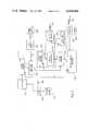
- FIG. 1is a schematic block diagram of the system in accordance with the present invention.
- FIG. 2is a schematic block diagram of a circuit for generating a linearly increasing signal for a predetermined period of time to be used in the apparatus shown in FIG. 1.
- FIG. 1there is shown a schematic representation of an embodiment of the present invention suitable for the injection of a radiopharmaceutical.
- a shunt 12is implanted in a subject 10, so that a portion of arterial blood flow may be routed outside the body of the subject and returned to a vein.
- Implanting shunt 12is a minor surgical procedure which might be performed by any medical doctor or, if the subject is not human, by any person with some surgical skill and experience in animal experimentation. Alternatively, a distal portion of an extremity may be placed between the detectors for a less invasive procedure.
- the radiopharmaceuticalis placed in automatic syringe 70, which is driven by servo motor 60, and connected to a vein in the subject by catheter 72.
- the connection of catheter 72is an even more minor surgical procedure, which might be carried out by any of the persons described above.
- Shunt 12is positioned between NaI(T1) (sodium iodide thermoluminesent) detectors 20a and 20b, which are positioned on opposite sides of shunt 12 to detect the coincident gamma ray pair created by the positron/electron annihilation.
- the outputs of detectors 20a and 20bwhich are light pulses, are converted to electrical signals by photomultipliers 21a and 21b and preamps 22a and 22b and amplified by amplifiers 24a and 24b.
- the output of amplifiers of 24a and 24bis a pulse whose height is proportional to the energy of the gamma ray detected by detectors 20a and 20b.
- This outputgoes to discriminators 26a and 26b, which are preset to produce an output pulse only for inputs corresponding to the appropriate gamma ray energy for positron/electron annihilation. These pulses pass through variable delays 28a and 28b, to coincidence detector 30.
- Coincidence detector 30produces an output only when two pulses reach it essentially simultaneously, and delays 28a and 28b are adjusted so that the total delay through each of the channels described is essentially equal.
- the output of coincidence detector 30is a pulse stream whose average rate is proportional to the rate of positron/electron annihilations, which in turn is proportional to the radiopharmaceutical concentration in the subject's blood stream.
- coincidence detector 30is connected to rate meter 32, which converts the average pulse rate in coincidence detector 30 into a continuous electrical signal which is connected to servo amplifier 50 and recorder 40.
- Generator 100which will be described more fully below, is connected to the other input servo amplifier 50.
- the output of function generator 100is a linearly increasing ramp which ranges from 0 to full scale in a predetermined period of time.
- the output of servo amplifier 50is an error signal; proportional to the difference between the output of rate meter 32 and the output of function generator 100, which controls servo motor 60 so as to increase or decrease the rate of injection from syringe 70 into subject 10, so that the concentration of radiopharmaceutical in the blood stream of subject 10 tracks the output of function generator 100 and is a linearly increasing function of time.
- concentration of radiopharmaceuticalis a linearly increasing function
- concentration of the blood streammay be desirable to maintain the concentration of the blood stream at a constant level or at an exponentially changing level.
- FIG. 2there is shown a schematic block diagram of function generator 100 in accordance with the present invention which provides an output reference signal which increases linearly from 0 to full scale at a preselected rate.
- a start signalis provided from a conventional switch 102, or other similar means, such as a relay.
- a reset pulsewill be provided on reset line 103 to set function generator 100, to an initial state.
- the start signalwill complete a circuit electrically connecting oscillator 110, which will typically operate at a frequency in excess of 100,000 Hz ⁇ approximately 0.01% and start lapsed time display 104.
- the operating frequencyis then frequency divided down to an output frequency of about 20 Hz, which is connected to ten-stage binary counter 112. At each successive stage of counter 112 the frequency is divided by a factor of 2 (i.e., at the output of the first stage the frequency is 10 Hz, at the second 5 Hz, etc.).
- the output of each of the stages of counter 112is connected to an input of count rate selector 113.
- the output of count rate selector 113is one of the ten frequencies produced by counter 112 and selected by setting sweep time selector switch 122. Sweep time selector switch 122 is also connected to sweep time display 124, to display the selected sweep time.
- the output of count rate selector 113is connected to the input of binary counter 114 and to the least significant bit of digital-to-analog converter 116.
- the nine stages of counter 114are sequentially connected to the remaining nine inputs of digital-to-analog converter 116.
- the output of digital-to-analog converter 116increases by a fixed amount each time counter 114 is incremented to form a staircase approximation of a linearly increasing function ranging from 0 to approximately 10 volts.
- the duration of this functionis determined by the output of count rate selector 113, and ranges from a minimum of approximately one minute forty-two seconds, to a maximum of approximately fourteen hours and thirty-two minutes in ten steps, each step being twice as long as the preceding step.
- the output of digital-to-analog converter 116is attenuated by attenuator 118 to a range of from 0 to about one volt, so as to be compatible with servo amplifier 50.
- the attenuated outputis connected to servo amplifier 50 on line 119 and is also displayed on digital volt meter 120.
- One possible hazard associated with the apparatus shown in FIG. 1is that a failure in the function generator 100 might cause a sudden large change in the output of digital-to-analog converter 116. If servo amplifier 50 were to follow this erroneous output, the sudden increase in the injection rate would cause a hydrostatic shock in the blood stream of subject 10, with possibly serious harmful effects. To prevent this, safety circuit 130 is incorporated into function generator 100.
- Safety circuit 130comprises a second nine stage binary counter 132, which is also connected to the output count rate selector 113.
- the states of counters 132 and 114are compared by digital comparator 134, whose output is connected to failure indicator 138.
- failure indicator 138shows a failure and outputs a stop signal on line 139 to servo amplifier 50 to stop servo motor 60.
- amplitude discriminator 136is connected to the output of digital-to-analog converter 116, and the output of amplitude discriminator 136 is also connected to failure indicator 138.
- Amplitude discriminator 136produces an output if there is a sudden sharp change in the output of digital-to-analogue converter 116, which exceeds a certain preselected magnitude. Thus, failure circuit 130 will prevent servo amplifier 50 from trying to follow sudden sharp changes in the output of function generator 100.
- the physiological state of the animalwas altered by increasing partial pressure of carbon dioxide in the arterial blood flow at discrete times during the injection.
- An increase in CO 2 pressureshould increase the rate of cerebral blood flow and a change in cerebral blood flow was detected with a PETT III tomograph.
- This experimentdemonstrated that a linearly increasing concentration of the radiopharmaceutical could be maintained for an extended period in an animal under physiologically altered conditions.
Landscapes
- Health & Medical Sciences (AREA)
- Life Sciences & Earth Sciences (AREA)
- Medical Informatics (AREA)
- Engineering & Computer Science (AREA)
- Radiology & Medical Imaging (AREA)
- Biomedical Technology (AREA)
- Biophysics (AREA)
- Nuclear Medicine, Radiotherapy & Molecular Imaging (AREA)
- Optics & Photonics (AREA)
- Pathology (AREA)
- Physics & Mathematics (AREA)
- High Energy & Nuclear Physics (AREA)
- Heart & Thoracic Surgery (AREA)
- Molecular Biology (AREA)
- Surgery (AREA)
- Animal Behavior & Ethology (AREA)
- General Health & Medical Sciences (AREA)
- Public Health (AREA)
- Veterinary Medicine (AREA)
- Nuclear Medicine (AREA)
Abstract
Description
Claims (8)
Priority Applications (1)
| Application Number | Priority Date | Filing Date | Title |
|---|---|---|---|
| US06/268,423US4409966A (en) | 1981-05-29 | 1981-05-29 | Method and apparatus for injecting a substance into the bloodstream of a subject |
Applications Claiming Priority (1)
| Application Number | Priority Date | Filing Date | Title |
|---|---|---|---|
| US06/268,423US4409966A (en) | 1981-05-29 | 1981-05-29 | Method and apparatus for injecting a substance into the bloodstream of a subject |
Publications (1)
| Publication Number | Publication Date |
|---|---|
| US4409966Atrue US4409966A (en) | 1983-10-18 |
Family
ID=23022933
Family Applications (1)
| Application Number | Title | Priority Date | Filing Date |
|---|---|---|---|
| US06/268,423Expired - Fee RelatedUS4409966A (en) | 1981-05-29 | 1981-05-29 | Method and apparatus for injecting a substance into the bloodstream of a subject |
Country Status (1)
| Country | Link |
|---|---|
| US (1) | US4409966A (en) |
Cited By (64)
| Publication number | Priority date | Publication date | Assignee | Title |
|---|---|---|---|---|
| US4508532A (en)* | 1983-09-09 | 1985-04-02 | Ninetronix, Inc. | Ophthalmic aspirator/irrigator and cystotome |
| US4551133A (en)* | 1984-04-16 | 1985-11-05 | American Hospital Supply Corporation | Patient controlled medication infusion system |
| US5320503A (en) | 1988-05-17 | 1994-06-14 | Patient Solutions Inc. | Infusion device with disposable elements |
| US5455022A (en)* | 1993-09-09 | 1995-10-03 | Associated Universities, Inc. | Halogenated sulfidohydroboranes for nuclear medicine and boron neutron capture therapy |
| US5520637A (en)* | 1995-01-31 | 1996-05-28 | Pager; David | Closed-loop system for infusing oxytocin |
| US5584667A (en) | 1988-05-17 | 1996-12-17 | Davis; David L. | Method of providing uniform flow from an infusion device |
| US5803712A (en) | 1988-05-17 | 1998-09-08 | Patient Solutions, Inc. | Method of measuring an occlusion in an infusion device with disposable elements |
| US5876378A (en)* | 1996-09-20 | 1999-03-02 | Mbadugha; Joseph O. | Apparatus and method for injecting liquids into patients |
| US5993374A (en)* | 1997-06-17 | 1999-11-30 | Radiance Medical Systems, Inc. | Microcapsules for site-specific delivery |
| US20020026148A1 (en)* | 1993-10-28 | 2002-02-28 | Medrad, Inc. | Multi-patient fluid dispensing |
| US20030014132A1 (en)* | 2000-02-07 | 2003-01-16 | Hiroyuki Ohba | Positron emission tomograph |
| US20030050556A1 (en)* | 1994-09-21 | 2003-03-13 | Uber Arthur E. | Patient specific dosing contrast delivery systems and methods |
| US6767319B2 (en) | 2001-06-29 | 2004-07-27 | Medrad, Inc. | Delivery methods, systems and components for use with hazardous pharmaceutical substances |
| US20050099624A1 (en)* | 2003-11-07 | 2005-05-12 | Staehr Linda B. | Fluid verification system and method for infusions |
| US6901283B2 (en) | 1993-10-28 | 2005-05-31 | Medrad, Inc. | Adjusting a condition of a fluid medium to produce an image of a patient |
| US7037277B1 (en) | 1998-07-21 | 2006-05-02 | Spectrx, Inc. | System and method for fluid management in a continuous fluid collection and sensor device |
| US20070255135A1 (en)* | 2004-11-16 | 2007-11-01 | Medrad, Inc. | Systems and methods of modeling pharmaceutical propagation in a patient |
| US7384396B2 (en) | 1998-07-21 | 2008-06-10 | Spectrx Inc. | System and method for continuous analyte monitoring |
| US20090131862A1 (en)* | 2004-07-16 | 2009-05-21 | Universitat Zurich | Method and device for accurate dispensing of radioactivity |
| US20090226867A1 (en)* | 2008-03-04 | 2009-09-10 | Medrad, Inc. | Dynamic anthropomorphic cardiovascular phantom |
| US20090316970A1 (en)* | 2008-06-24 | 2009-12-24 | Medrad, Inc. | Identification of regions of interest and extraction of time value curves in imaging procedures |
| US20100030073A1 (en)* | 2006-12-29 | 2010-02-04 | Medrad, Inc. | Modeling of pharmaceutical propagation |
| US20100069786A1 (en)* | 2006-06-29 | 2010-03-18 | Depuy Spine, Inc. | Integrated bone biopsy and therapy apparatus |
| US20100113887A1 (en)* | 2006-12-29 | 2010-05-06 | Medrad, Inc. | Patient-based parameter generation systems for medical injection procedures |
| US20100204572A1 (en)* | 2007-07-17 | 2010-08-12 | Medrad, Inc. | Devices, Systems and Methods for Determination of Parameters for a Procedure, for Estimation of Cardiopulmonary Function and for Fluid Delivery |
| US7925330B2 (en) | 2004-11-24 | 2011-04-12 | Medrad, Inc. | Devices, systems and methods for determining parameters of one or more phases of an injection procedure |
| US20110178359A1 (en)* | 2007-01-01 | 2011-07-21 | Hirschman Alan D | Systems For Integrated Radiopharmaceutical Generation, Preparation, Transportation and Administration |
| US20110209764A1 (en)* | 2008-06-06 | 2011-09-01 | Uber Arthur E | Apparatus and Methods for Delivery of Fluid Injection Boluses to Patients and Handling Harmful Fluids |
| US8066713B2 (en) | 2003-03-31 | 2011-11-29 | Depuy Spine, Inc. | Remotely-activated vertebroplasty injection device |
| US20120226222A1 (en)* | 2009-11-23 | 2012-09-06 | Spark S.R.L. | Device For Dosing And Adjusting The Flow Of A Radiopaque Agent To Be Used In Performing An Angiography |
| US8361078B2 (en) | 2003-06-17 | 2013-01-29 | Depuy Spine, Inc. | Methods, materials and apparatus for treating bone and other tissue |
| US8360629B2 (en) | 2005-11-22 | 2013-01-29 | Depuy Spine, Inc. | Mixing apparatus having central and planetary mixing elements |
| US8415407B2 (en) | 2004-03-21 | 2013-04-09 | Depuy Spine, Inc. | Methods, materials, and apparatus for treating bone and other tissue |
| US8579908B2 (en) | 2003-09-26 | 2013-11-12 | DePuy Synthes Products, LLC. | Device for delivering viscous material |
| US8950929B2 (en) | 2006-10-19 | 2015-02-10 | DePuy Synthes Products, LLC | Fluid delivery system |
| US8992541B2 (en) | 2003-03-14 | 2015-03-31 | DePuy Synthes Products, LLC | Hydraulic device for the injection of bone cement in percutaneous vertebroplasty |
| US9039592B2 (en) | 2012-06-07 | 2015-05-26 | Bayer Medical Care Inc. | Radiopharmaceutical delivery device |
| US9108047B2 (en) | 2010-06-04 | 2015-08-18 | Bayer Medical Care Inc. | System and method for planning and monitoring multi-dose radiopharmaceutical usage on radiopharmaceutical injectors |
| US9125976B2 (en) | 2012-06-07 | 2015-09-08 | Bayer Medical Care Inc. | Shield adapters |
| US9233776B2 (en) | 2012-06-07 | 2016-01-12 | Bayer Healthcare Llc | Molecular imaging vial transport container and fluid injection system interface |
| US9327886B2 (en) | 2013-03-13 | 2016-05-03 | Bayer Healthcare Llc | Vial container with collar cap |
| US9381024B2 (en) | 2005-07-31 | 2016-07-05 | DePuy Synthes Products, Inc. | Marked tools |
| US9393441B2 (en) | 2012-06-07 | 2016-07-19 | Bayer Healthcare Llc | Radiopharmaceutical delivery and tube management system |
| US9421330B2 (en) | 2008-11-03 | 2016-08-23 | Bayer Healthcare Llc | Mitigation of contrast-induced nephropathy |
| US9433728B2 (en) | 2013-03-01 | 2016-09-06 | Bayer Healthcare Llc | Valveless pharmaceutical infusion system |
| US9642932B2 (en) | 2006-09-14 | 2017-05-09 | DePuy Synthes Products, Inc. | Bone cement and methods of use thereof |
| US9700672B2 (en) | 2011-09-21 | 2017-07-11 | Bayer Healthcare Llc | Continuous multi-fluid pump device, drive and actuating system and method |
| US9757306B2 (en) | 2013-03-13 | 2017-09-12 | Bayer Healthcare Llc | Vial container with collar cap |
| US9889288B2 (en) | 2012-06-07 | 2018-02-13 | Bayer Healthcare Llc | Tubing connectors |
| US9918767B2 (en) | 2005-08-01 | 2018-03-20 | DePuy Synthes Products, Inc. | Temperature control system |
| US9949704B2 (en) | 2012-05-14 | 2018-04-24 | Bayer Healthcare Llc | Systems and methods for determination of pharmaceutical fluid injection protocols based on x-ray tube voltage |
| US9959389B2 (en) | 2010-06-24 | 2018-05-01 | Bayer Healthcare Llc | Modeling of pharmaceutical propagation and parameter generation for injection protocols |
| US10507319B2 (en) | 2015-01-09 | 2019-12-17 | Bayer Healthcare Llc | Multiple fluid delivery system with multi-use disposable set and features thereof |
| US10898638B2 (en) | 2016-03-03 | 2021-01-26 | Bayer Healthcare Llc | System and method for improved fluid delivery in multi-fluid injector systems |
| US11141535B2 (en) | 2017-08-31 | 2021-10-12 | Bayer Healthcare Llc | Fluid path impedance assessment for improving fluid delivery performance |
| US11278853B2 (en) | 2013-03-13 | 2022-03-22 | Bayer Healthcare Llc | Method for controlling fluid accuracy and backflow compensation |
| US11478581B2 (en) | 2017-08-31 | 2022-10-25 | Bayer Healthcare Llc | Fluid injector system volume compensation system and method |
| US11598664B2 (en) | 2017-08-31 | 2023-03-07 | Bayer Healthcare Llc | Injector pressure calibration system and method |
| US11779702B2 (en) | 2017-08-31 | 2023-10-10 | Bayer Healthcare Llc | Method for dynamic pressure control in a fluid injector system |
| US11786652B2 (en) | 2017-08-31 | 2023-10-17 | Bayer Healthcare Llc | System and method for drive member position and fluid injector system mechanical calibration |
| US12208239B2 (en) | 2018-08-28 | 2025-01-28 | Bayer Healthcare Llc | Fluid injector system, method of preventing fluid backflow, and computer program product |
| US12251544B2 (en) | 2018-04-19 | 2025-03-18 | Bayer Healthcare Llc | System and method for air detection in fluid injector |
| US12263326B2 (en) | 2016-11-14 | 2025-04-01 | Bayer Healthcare Llc | Methods and systems for verifying the contents of a syringe used for medical fluid delivery |
| US12427249B2 (en) | 2018-08-28 | 2025-09-30 | Bayer Healthcare Llc | Fluid injector system with improved ratio performance |
Citations (3)
| Publication number | Priority date | Publication date | Assignee | Title |
|---|---|---|---|---|
| US3847138A (en)* | 1973-03-14 | 1974-11-12 | S Gollub | Method and system for controlled automated administration of drugs to patients |
| US4224303A (en)* | 1978-07-21 | 1980-09-23 | A. C. Smith | Signalling particles for introduction into blood flowing through a vessel of interest |
| US4294248A (en)* | 1978-10-19 | 1981-10-13 | Figueiredo Nuno R M De | Device for automatically controlling the infusion liquid flow in an infusion apparatus |
- 1981
- 1981-05-29USUS06/268,423patent/US4409966A/ennot_activeExpired - Fee Related
Patent Citations (3)
| Publication number | Priority date | Publication date | Assignee | Title |
|---|---|---|---|---|
| US3847138A (en)* | 1973-03-14 | 1974-11-12 | S Gollub | Method and system for controlled automated administration of drugs to patients |
| US4224303A (en)* | 1978-07-21 | 1980-09-23 | A. C. Smith | Signalling particles for introduction into blood flowing through a vessel of interest |
| US4294248A (en)* | 1978-10-19 | 1981-10-13 | Figueiredo Nuno R M De | Device for automatically controlling the infusion liquid flow in an infusion apparatus |
Cited By (121)
| Publication number | Priority date | Publication date | Assignee | Title |
|---|---|---|---|---|
| US4508532A (en)* | 1983-09-09 | 1985-04-02 | Ninetronix, Inc. | Ophthalmic aspirator/irrigator and cystotome |
| US4551133A (en)* | 1984-04-16 | 1985-11-05 | American Hospital Supply Corporation | Patient controlled medication infusion system |
| US6146109A (en) | 1988-05-17 | 2000-11-14 | Alaris Medical Systems, Inc. | Infusion device with disposable elements |
| US5584667A (en) | 1988-05-17 | 1996-12-17 | Davis; David L. | Method of providing uniform flow from an infusion device |
| US5803712A (en) | 1988-05-17 | 1998-09-08 | Patient Solutions, Inc. | Method of measuring an occlusion in an infusion device with disposable elements |
| US6742992B2 (en) | 1988-05-17 | 2004-06-01 | I-Flow Corporation | Infusion device with disposable elements |
| US6312227B1 (en) | 1988-05-17 | 2001-11-06 | I-Flow Corp. | Infusion device with disposable elements |
| US5320503A (en) | 1988-05-17 | 1994-06-14 | Patient Solutions Inc. | Infusion device with disposable elements |
| US5455022A (en)* | 1993-09-09 | 1995-10-03 | Associated Universities, Inc. | Halogenated sulfidohydroboranes for nuclear medicine and boron neutron capture therapy |
| US6901283B2 (en) | 1993-10-28 | 2005-05-31 | Medrad, Inc. | Adjusting a condition of a fluid medium to produce an image of a patient |
| US7427281B2 (en) | 1993-10-28 | 2008-09-23 | Medrad, Inc. | Method of delivering fluid mixtures to multiple patients |
| US20020026148A1 (en)* | 1993-10-28 | 2002-02-28 | Medrad, Inc. | Multi-patient fluid dispensing |
| US7313431B2 (en) | 1994-09-21 | 2007-12-25 | Medrad, Inc. | System and method for inflating a balloon catheter and delivering fluid media to a patient |
| US20030050556A1 (en)* | 1994-09-21 | 2003-03-13 | Uber Arthur E. | Patient specific dosing contrast delivery systems and methods |
| US5520637A (en)* | 1995-01-31 | 1996-05-28 | Pager; David | Closed-loop system for infusing oxytocin |
| US5876378A (en)* | 1996-09-20 | 1999-03-02 | Mbadugha; Joseph O. | Apparatus and method for injecting liquids into patients |
| US5993374A (en)* | 1997-06-17 | 1999-11-30 | Radiance Medical Systems, Inc. | Microcapsules for site-specific delivery |
| US7384396B2 (en) | 1998-07-21 | 2008-06-10 | Spectrx Inc. | System and method for continuous analyte monitoring |
| US7037277B1 (en) | 1998-07-21 | 2006-05-02 | Spectrx, Inc. | System and method for fluid management in a continuous fluid collection and sensor device |
| US20030014132A1 (en)* | 2000-02-07 | 2003-01-16 | Hiroyuki Ohba | Positron emission tomograph |
| US7191109B2 (en) | 2000-02-07 | 2007-03-13 | Hamamatsu Photonics K.K. | Positron emission tomograph apparatus |
| EP1256817A4 (en)* | 2000-02-07 | 2003-05-21 | Hamamatsu Photonics Kk | Positron emission tomograph |
| US20050238576A1 (en)* | 2001-06-29 | 2005-10-27 | Dell Mary A | Delivery methods, systems and components for use with radiopharmaceutical substances |
| US6767319B2 (en) | 2001-06-29 | 2004-07-27 | Medrad, Inc. | Delivery methods, systems and components for use with hazardous pharmaceutical substances |
| US9186194B2 (en) | 2003-03-14 | 2015-11-17 | DePuy Synthes Products, Inc. | Hydraulic device for the injection of bone cement in percutaneous vertebroplasty |
| US8992541B2 (en) | 2003-03-14 | 2015-03-31 | DePuy Synthes Products, LLC | Hydraulic device for the injection of bone cement in percutaneous vertebroplasty |
| US10799278B2 (en) | 2003-03-14 | 2020-10-13 | DePuy Synthes Products, Inc. | Hydraulic device for the injection of bone cement in percutaneous vertebroplasty |
| US8066713B2 (en) | 2003-03-31 | 2011-11-29 | Depuy Spine, Inc. | Remotely-activated vertebroplasty injection device |
| US8333773B2 (en)* | 2003-03-31 | 2012-12-18 | Depuy Spine, Inc. | Remotely-activated vertebroplasty injection device |
| US10485597B2 (en) | 2003-03-31 | 2019-11-26 | DePuy Synthes Products, Inc. | Remotely-activated vertebroplasty injection device |
| US9839460B2 (en) | 2003-03-31 | 2017-12-12 | DePuy Synthes Products, Inc. | Remotely-activated vertebroplasty injection device |
| US8361078B2 (en) | 2003-06-17 | 2013-01-29 | Depuy Spine, Inc. | Methods, materials and apparatus for treating bone and other tissue |
| US10039585B2 (en) | 2003-06-17 | 2018-08-07 | DePuy Synthes Products, Inc. | Methods, materials and apparatus for treating bone and other tissue |
| US9504508B2 (en) | 2003-06-17 | 2016-11-29 | DePuy Synthes Products, Inc. | Methods, materials and apparatus for treating bone and other tissue |
| US8540722B2 (en) | 2003-06-17 | 2013-09-24 | DePuy Synthes Products, LLC | Methods, materials and apparatus for treating bone and other tissue |
| US8956368B2 (en) | 2003-06-17 | 2015-02-17 | DePuy Synthes Products, LLC | Methods, materials and apparatus for treating bone and other tissue |
| US10111697B2 (en) | 2003-09-26 | 2018-10-30 | DePuy Synthes Products, Inc. | Device for delivering viscous material |
| US8579908B2 (en) | 2003-09-26 | 2013-11-12 | DePuy Synthes Products, LLC. | Device for delivering viscous material |
| US20050099624A1 (en)* | 2003-11-07 | 2005-05-12 | Staehr Linda B. | Fluid verification system and method for infusions |
| US7256888B2 (en) | 2003-11-07 | 2007-08-14 | Cardial Health 303, Inc. | Fluid verification system and method for infusions |
| US8809418B2 (en) | 2004-03-21 | 2014-08-19 | DePuy Synthes Products, LLC | Methods, materials and apparatus for treating bone and other tissue |
| US9750840B2 (en) | 2004-03-21 | 2017-09-05 | DePuy Synthes Products, Inc. | Methods, materials and apparatus for treating bone and other tissue |
| US8415407B2 (en) | 2004-03-21 | 2013-04-09 | Depuy Spine, Inc. | Methods, materials, and apparatus for treating bone and other tissue |
| US8517905B2 (en) | 2004-07-16 | 2013-08-27 | University Of Zurich | Method and device for accurate dispensing of radioactivity |
| US9295857B2 (en) | 2004-07-16 | 2016-03-29 | University Of Zurich | Method and device for accurate dispensing of radioactivity |
| US8852071B2 (en) | 2004-07-16 | 2014-10-07 | Bayer Medical Care Inc. | Method and device for accurate dispensing of radioactivity |
| US9717928B2 (en) | 2004-07-16 | 2017-08-01 | University Of Zurich | Method and device for accurate dispensing of radioactivity |
| US20090131862A1 (en)* | 2004-07-16 | 2009-05-21 | Universitat Zurich | Method and device for accurate dispensing of radioactivity |
| US8295914B2 (en) | 2004-11-16 | 2012-10-23 | Medrad, Inc. | Systems and methods of determining patient transfer functions and modeling patient response to a pharmaceutical injection |
| US8197437B2 (en) | 2004-11-16 | 2012-06-12 | Medrad, Inc. | Systems and methods of modeling pharmaceutical propagation in a patient |
| US20080097197A1 (en)* | 2004-11-16 | 2008-04-24 | Kalafut John F | Modeling of Pharmaceutical Propagation |
| US8346342B2 (en) | 2004-11-16 | 2013-01-01 | Medrad, Inc. | Systems and methods of determining patient physiological parameters from an imaging procedure |
| US20070255135A1 (en)* | 2004-11-16 | 2007-11-01 | Medrad, Inc. | Systems and methods of modeling pharmaceutical propagation in a patient |
| US9616166B2 (en) | 2004-11-16 | 2017-04-11 | Bayer Healthcare Llc | Systems and methods of determining injection protocols for diagnostic imaging procedures |
| US7925330B2 (en) | 2004-11-24 | 2011-04-12 | Medrad, Inc. | Devices, systems and methods for determining parameters of one or more phases of an injection procedure |
| US9950107B2 (en) | 2004-11-24 | 2018-04-24 | Bayer Healthcare Llc | Systems and methods for managing workflow for injection procedures |
| US9238099B2 (en) | 2004-11-24 | 2016-01-19 | Bayer Healthcare Llc | System and apparatus for modeling pressures generated during an injection procedure |
| US10166326B2 (en) | 2004-11-24 | 2019-01-01 | Bayer Healthcare Llc | Devices, systems and methods for determining parameters of one or more phases of an injection procedure |
| US9381024B2 (en) | 2005-07-31 | 2016-07-05 | DePuy Synthes Products, Inc. | Marked tools |
| US9918767B2 (en) | 2005-08-01 | 2018-03-20 | DePuy Synthes Products, Inc. | Temperature control system |
| US10631906B2 (en) | 2005-11-22 | 2020-04-28 | DePuy Synthes Products, Inc. | Apparatus for transferring a viscous material |
| US8360629B2 (en) | 2005-11-22 | 2013-01-29 | Depuy Spine, Inc. | Mixing apparatus having central and planetary mixing elements |
| US9259696B2 (en) | 2005-11-22 | 2016-02-16 | DePuy Synthes Products, Inc. | Mixing apparatus having central and planetary mixing elements |
| US20100069786A1 (en)* | 2006-06-29 | 2010-03-18 | Depuy Spine, Inc. | Integrated bone biopsy and therapy apparatus |
| US9642932B2 (en) | 2006-09-14 | 2017-05-09 | DePuy Synthes Products, Inc. | Bone cement and methods of use thereof |
| US10272174B2 (en) | 2006-09-14 | 2019-04-30 | DePuy Synthes Products, Inc. | Bone cement and methods of use thereof |
| US10494158B2 (en) | 2006-10-19 | 2019-12-03 | DePuy Synthes Products, Inc. | Fluid delivery system |
| US8950929B2 (en) | 2006-10-19 | 2015-02-10 | DePuy Synthes Products, LLC | Fluid delivery system |
| US20100113887A1 (en)* | 2006-12-29 | 2010-05-06 | Medrad, Inc. | Patient-based parameter generation systems for medical injection procedures |
| US20100030073A1 (en)* | 2006-12-29 | 2010-02-04 | Medrad, Inc. | Modeling of pharmaceutical propagation |
| US9302044B2 (en) | 2006-12-29 | 2016-04-05 | Bayer Healthcare Llc | Patient-based parameter generation systems for medical injection procedures |
| US10463782B2 (en) | 2006-12-29 | 2019-11-05 | Bayer Healthcare Llc | Patient-based parameter generation systems for medical injection procedures |
| US9326742B2 (en) | 2007-01-01 | 2016-05-03 | Bayer Healthcare Llc | Systems for integrated radiopharmaceutical generation, preparation, transportation and administration |
| US10016618B2 (en) | 2007-01-01 | 2018-07-10 | Bayer Healthcare Llc | Methods and systems for integrated radiopharmaceutical generation, preparation, transportation and administration |
| US20110178359A1 (en)* | 2007-01-01 | 2011-07-21 | Hirschman Alan D | Systems For Integrated Radiopharmaceutical Generation, Preparation, Transportation and Administration |
| US8428694B2 (en) | 2007-07-17 | 2013-04-23 | Medrad, Inc. | Methods for determination of parameters for a procedure, for estimation of cardiopulmonary function and for fluid delivery |
| US20100204572A1 (en)* | 2007-07-17 | 2010-08-12 | Medrad, Inc. | Devices, Systems and Methods for Determination of Parameters for a Procedure, for Estimation of Cardiopulmonary Function and for Fluid Delivery |
| US9008759B2 (en) | 2007-07-17 | 2015-04-14 | Bayer Medical Care Inc. | Devices and systems for determination of parameters for a procedure, for estimation of cardiopulmonary function and for fluid delivery |
| US20090226867A1 (en)* | 2008-03-04 | 2009-09-10 | Medrad, Inc. | Dynamic anthropomorphic cardiovascular phantom |
| US8608484B2 (en) | 2008-03-04 | 2013-12-17 | Medrad, Inc. | Dynamic anthropomorphic cardiovascular phantom |
| US9056200B2 (en) | 2008-06-06 | 2015-06-16 | Bayer Medical Care Inc. | Apparatus and methods for delivery of fluid injection boluses to patients and handling harmful fluids |
| US9750953B2 (en) | 2008-06-06 | 2017-09-05 | Bayer Healthcare Llc | Apparatus and methods for delivery of fluid injection boluses to patients and handling harmful fluids |
| US20110209764A1 (en)* | 2008-06-06 | 2011-09-01 | Uber Arthur E | Apparatus and Methods for Delivery of Fluid Injection Boluses to Patients and Handling Harmful Fluids |
| US8699770B2 (en) | 2008-06-24 | 2014-04-15 | Bayer Medical Care Inc. | Identification of regions of interest and extraction of time value curves in imaging procedures |
| US8315449B2 (en) | 2008-06-24 | 2012-11-20 | Medrad, Inc. | Identification of regions of interest and extraction of time value curves in imaging procedures |
| US20090316970A1 (en)* | 2008-06-24 | 2009-12-24 | Medrad, Inc. | Identification of regions of interest and extraction of time value curves in imaging procedures |
| US9421330B2 (en) | 2008-11-03 | 2016-08-23 | Bayer Healthcare Llc | Mitigation of contrast-induced nephropathy |
| US20120226222A1 (en)* | 2009-11-23 | 2012-09-06 | Spark S.R.L. | Device For Dosing And Adjusting The Flow Of A Radiopaque Agent To Be Used In Performing An Angiography |
| US9108047B2 (en) | 2010-06-04 | 2015-08-18 | Bayer Medical Care Inc. | System and method for planning and monitoring multi-dose radiopharmaceutical usage on radiopharmaceutical injectors |
| US9463335B2 (en) | 2010-06-04 | 2016-10-11 | Bayer Healthcare Llc | System and method for planning and monitoring multi-dose radiopharmaceutical usage on radiopharmaceutical injectors |
| US9959389B2 (en) | 2010-06-24 | 2018-05-01 | Bayer Healthcare Llc | Modeling of pharmaceutical propagation and parameter generation for injection protocols |
| US9700672B2 (en) | 2011-09-21 | 2017-07-11 | Bayer Healthcare Llc | Continuous multi-fluid pump device, drive and actuating system and method |
| US11191501B2 (en) | 2012-05-14 | 2021-12-07 | Bayer Healthcare Llc | Systems and methods for determination of pharmaceutical fluid injection protocols based on x-ray tube voltage |
| US9949704B2 (en) | 2012-05-14 | 2018-04-24 | Bayer Healthcare Llc | Systems and methods for determination of pharmaceutical fluid injection protocols based on x-ray tube voltage |
| US9889288B2 (en) | 2012-06-07 | 2018-02-13 | Bayer Healthcare Llc | Tubing connectors |
| US9125976B2 (en) | 2012-06-07 | 2015-09-08 | Bayer Medical Care Inc. | Shield adapters |
| US10272263B2 (en) | 2012-06-07 | 2019-04-30 | Bayer Healthcare Llc | Radiopharmaceutical delivery and tube management system |
| US9039592B2 (en) | 2012-06-07 | 2015-05-26 | Bayer Medical Care Inc. | Radiopharmaceutical delivery device |
| US9233776B2 (en) | 2012-06-07 | 2016-01-12 | Bayer Healthcare Llc | Molecular imaging vial transport container and fluid injection system interface |
| US9393441B2 (en) | 2012-06-07 | 2016-07-19 | Bayer Healthcare Llc | Radiopharmaceutical delivery and tube management system |
| US9707342B2 (en) | 2012-06-07 | 2017-07-18 | Bayer Healthcare | Shield adapted to fit medical injector syringe |
| US9433728B2 (en) | 2013-03-01 | 2016-09-06 | Bayer Healthcare Llc | Valveless pharmaceutical infusion system |
| US9327886B2 (en) | 2013-03-13 | 2016-05-03 | Bayer Healthcare Llc | Vial container with collar cap |
| US9757306B2 (en) | 2013-03-13 | 2017-09-12 | Bayer Healthcare Llc | Vial container with collar cap |
| US11278853B2 (en) | 2013-03-13 | 2022-03-22 | Bayer Healthcare Llc | Method for controlling fluid accuracy and backflow compensation |
| US10507319B2 (en) | 2015-01-09 | 2019-12-17 | Bayer Healthcare Llc | Multiple fluid delivery system with multi-use disposable set and features thereof |
| US12201802B2 (en) | 2015-01-09 | 2025-01-21 | Bayer Healthcare Llc | Multiple fluid delivery system with multi-use disposable set and features thereof |
| US11491318B2 (en) | 2015-01-09 | 2022-11-08 | Bayer Healthcare Llc | Multiple fluid delivery system with multi-use disposable set and features thereof |
| US11672902B2 (en) | 2016-03-03 | 2023-06-13 | Bayer Healthcare Llc | System and method for improved fluid delivery in multi-fluid injector systems |
| US10898638B2 (en) | 2016-03-03 | 2021-01-26 | Bayer Healthcare Llc | System and method for improved fluid delivery in multi-fluid injector systems |
| US12263326B2 (en) | 2016-11-14 | 2025-04-01 | Bayer Healthcare Llc | Methods and systems for verifying the contents of a syringe used for medical fluid delivery |
| US11826553B2 (en) | 2017-08-31 | 2023-11-28 | Bayer Healthcare Llc | Fluid path impedance assessment for improving fluid delivery performance |
| US11779702B2 (en) | 2017-08-31 | 2023-10-10 | Bayer Healthcare Llc | Method for dynamic pressure control in a fluid injector system |
| US11786652B2 (en) | 2017-08-31 | 2023-10-17 | Bayer Healthcare Llc | System and method for drive member position and fluid injector system mechanical calibration |
| US11478581B2 (en) | 2017-08-31 | 2022-10-25 | Bayer Healthcare Llc | Fluid injector system volume compensation system and method |
| US11141535B2 (en) | 2017-08-31 | 2021-10-12 | Bayer Healthcare Llc | Fluid path impedance assessment for improving fluid delivery performance |
| US12214155B2 (en) | 2017-08-31 | 2025-02-04 | Bayer Healthcare Llc | Fluid injector system volume compensation system and method |
| US11598664B2 (en) | 2017-08-31 | 2023-03-07 | Bayer Healthcare Llc | Injector pressure calibration system and method |
| US12251544B2 (en) | 2018-04-19 | 2025-03-18 | Bayer Healthcare Llc | System and method for air detection in fluid injector |
| US12208239B2 (en) | 2018-08-28 | 2025-01-28 | Bayer Healthcare Llc | Fluid injector system, method of preventing fluid backflow, and computer program product |
| US12427249B2 (en) | 2018-08-28 | 2025-09-30 | Bayer Healthcare Llc | Fluid injector system with improved ratio performance |
Similar Documents
| Publication | Publication Date | Title |
|---|---|---|
| US4409966A (en) | Method and apparatus for injecting a substance into the bloodstream of a subject | |
| Lassen et al. | Regional cerebral blood flow in man determined by krypton85 | |
| Ter-Pogossian et al. | The determination of regional cerebral blood flow by means of water labeled with radioactive oxygen 15 | |
| US4682604A (en) | Coincidence counting emission tomographic probe: method and apparatus | |
| US4755679A (en) | Method and apparatus for maximizing counts of a PET camera | |
| US3847138A (en) | Method and system for controlled automated administration of drugs to patients | |
| US3221731A (en) | Apparatus for evaluating the condition of the heart muscle | |
| Oldendorf et al. | Hematocrit of the human cranial blood pool | |
| US3982128A (en) | Dual crystal scintillation probe | |
| Donato et al. | Measurement of coronary blood flow by external counting with radioactive rubidium: Critical appraisal and validation of the method | |
| Votaw et al. | Performance evaluation of the Pico-Count flow through detector for use in cerebral blood flow PET studies | |
| Ten Haken et al. | Photon activation—15O decay studies of tumor blood flow | |
| Neuman et al. | Cardiopulmonary consequences of decompression stress | |
| Conn Jr | Use of external counting technics in studies of the circulation | |
| Saha et al. | Use of the 82Sr/82Rb generator in clinical PET studies | |
| Wilson et al. | Measurement of regional blood flow by the 133xenon inhalation method with an on-line computer | |
| Lapointe et al. | A microvolumetric blood counter/sampler for metabolic PET studies in small animals | |
| Hunter et al. | The use of caesium iodide mini scintillation counters for dual isotope pulmonary capillary permeability studies | |
| Shepherd et al. | Measurement of cardiac output in man by injection of dye at a constant rate into the right ventricle or pulmonary artery | |
| US3670715A (en) | Device for measuring the flow of blood | |
| US3618591A (en) | Cardiac output determination method for use with dye dilution procedures | |
| US4453075A (en) | Method for localizing a region in the human body, in particular venous thrombi, by the uptake of a radioactive substance, particularly 125 I- | |
| Watabe et al. | Development of skin surface radiation detector system to monitor radioactivity in arterial blood along with positron emission tomography | |
| MAcINTYRE et al. | A method for continuously recording the disappearance of radioactive tracers from circulating blood | |
| ASA et al. | Lymphatic drainage from subcutaneous tissue in the foot and leg in the sitting human |
Legal Events
| Date | Code | Title | Description |
|---|---|---|---|
| AS | Assignment | Owner name:UNITED STATES OF AMERICA, AS REPRESENTED BY THE UN Free format text:ASSIGNMENT OF ASSIGNORS INTEREST;ASSIGNORS:LAMBRECHT, RICHARD M.;BENNETT, GERALD W.;DUNCAN, CHARLES C.;AND OTHERS;REEL/FRAME:003922/0660 Effective date:19810427 Owner name:UNITED STATES OF AMERICA, AS REPRESENTED BY THE UN Free format text:ASSIGNMENT OF ASSIGNORS INTEREST.;ASSIGNORS:LAMBRECHT, RICHARD M.;BENNETT, GERALD W.;DUNCAN, CHARLES C.;AND OTHERS;REEL/FRAME:003922/0660 Effective date:19810427 | |
| MAFP | Maintenance fee payment | Free format text:PAYMENT OF MAINTENANCE FEE, 4TH YEAR, PL 96-517 (ORIGINAL EVENT CODE: M170); ENTITY STATUS OF PATENT OWNER: LARGE ENTITY Year of fee payment:4 | |
| FEPP | Fee payment procedure | Free format text:MAINTENANCE FEE REMINDER MAILED (ORIGINAL EVENT CODE: REM.); ENTITY STATUS OF PATENT OWNER: LARGE ENTITY | |
| LAPS | Lapse for failure to pay maintenance fees | ||
| FP | Lapsed due to failure to pay maintenance fee | Effective date:19911020 | |
| STCH | Information on status: patent discontinuation | Free format text:PATENT EXPIRED DUE TO NONPAYMENT OF MAINTENANCE FEES UNDER 37 CFR 1.362 |