US4409695A - Adjustable bed for morbidly obese patients - Google Patents
Adjustable bed for morbidly obese patientsDownload PDFInfo
- Publication number
- US4409695A US4409695AUS06/281,175US28117581AUS4409695AUS 4409695 AUS4409695 AUS 4409695AUS 28117581 AUS28117581 AUS 28117581AUS 4409695 AUS4409695 AUS 4409695A
- Authority
- US
- United States
- Prior art keywords
- foot
- section
- bed
- patient
- center section
- Prior art date
- Legal status (The legal status is an assumption and is not a legal conclusion. Google has not performed a legal analysis and makes no representation as to the accuracy of the status listed.)
- Expired - Lifetime
Links
Images


Classifications
- A—HUMAN NECESSITIES
- A61—MEDICAL OR VETERINARY SCIENCE; HYGIENE
- A61G—TRANSPORT, PERSONAL CONVEYANCES, OR ACCOMMODATION SPECIALLY ADAPTED FOR PATIENTS OR DISABLED PERSONS; OPERATING TABLES OR CHAIRS; CHAIRS FOR DENTISTRY; FUNERAL DEVICES
- A61G7/00—Beds specially adapted for nursing; Devices for lifting patients or disabled persons
- A61G7/05—Parts, details or accessories of beds
- A61G7/0507—Side-rails
- A—HUMAN NECESSITIES
- A61—MEDICAL OR VETERINARY SCIENCE; HYGIENE
- A61G—TRANSPORT, PERSONAL CONVEYANCES, OR ACCOMMODATION SPECIALLY ADAPTED FOR PATIENTS OR DISABLED PERSONS; OPERATING TABLES OR CHAIRS; CHAIRS FOR DENTISTRY; FUNERAL DEVICES
- A61G7/00—Beds specially adapted for nursing; Devices for lifting patients or disabled persons
- A61G7/002—Beds specially adapted for nursing; Devices for lifting patients or disabled persons having adjustable mattress frame
- A61G7/015—Beds specially adapted for nursing; Devices for lifting patients or disabled persons having adjustable mattress frame divided into different adjustable sections, e.g. for Gatch position
- A—HUMAN NECESSITIES
- A61—MEDICAL OR VETERINARY SCIENCE; HYGIENE
- A61G—TRANSPORT, PERSONAL CONVEYANCES, OR ACCOMMODATION SPECIALLY ADAPTED FOR PATIENTS OR DISABLED PERSONS; OPERATING TABLES OR CHAIRS; CHAIRS FOR DENTISTRY; FUNERAL DEVICES
- A61G7/00—Beds specially adapted for nursing; Devices for lifting patients or disabled persons
- A61G7/05—Parts, details or accessories of beds
- A61G7/0507—Side-rails
- A61G7/0508—Side-rails characterised by a particular connection mechanism
- A61G7/051—Side-rails characterised by a particular connection mechanism pivoting sideward
- A—HUMAN NECESSITIES
- A61—MEDICAL OR VETERINARY SCIENCE; HYGIENE
- A61G—TRANSPORT, PERSONAL CONVEYANCES, OR ACCOMMODATION SPECIALLY ADAPTED FOR PATIENTS OR DISABLED PERSONS; OPERATING TABLES OR CHAIRS; CHAIRS FOR DENTISTRY; FUNERAL DEVICES
- A61G7/00—Beds specially adapted for nursing; Devices for lifting patients or disabled persons
- A61G7/05—Parts, details or accessories of beds
- A61G7/0507—Side-rails
- A61G7/0512—Side-rails characterised by customised length
- A61G7/0513—Side-rails characterised by customised length covering particular sections of the bed, e.g. one or more partial side-rail sections along the bed
- A—HUMAN NECESSITIES
- A61—MEDICAL OR VETERINARY SCIENCE; HYGIENE
- A61G—TRANSPORT, PERSONAL CONVEYANCES, OR ACCOMMODATION SPECIALLY ADAPTED FOR PATIENTS OR DISABLED PERSONS; OPERATING TABLES OR CHAIRS; CHAIRS FOR DENTISTRY; FUNERAL DEVICES
- A61G7/00—Beds specially adapted for nursing; Devices for lifting patients or disabled persons
- A61G7/05—Parts, details or accessories of beds
- A61G7/0507—Side-rails
- A61G7/052—Side-rails characterised by safety means, e.g. to avoid injuries to patient or caregiver
- A—HUMAN NECESSITIES
- A61—MEDICAL OR VETERINARY SCIENCE; HYGIENE
- A61G—TRANSPORT, PERSONAL CONVEYANCES, OR ACCOMMODATION SPECIALLY ADAPTED FOR PATIENTS OR DISABLED PERSONS; OPERATING TABLES OR CHAIRS; CHAIRS FOR DENTISTRY; FUNERAL DEVICES
- A61G7/00—Beds specially adapted for nursing; Devices for lifting patients or disabled persons
- A61G7/05—Parts, details or accessories of beds
- A61G7/0525—Side-bolsters
- A—HUMAN NECESSITIES
- A61—MEDICAL OR VETERINARY SCIENCE; HYGIENE
- A61G—TRANSPORT, PERSONAL CONVEYANCES, OR ACCOMMODATION SPECIALLY ADAPTED FOR PATIENTS OR DISABLED PERSONS; OPERATING TABLES OR CHAIRS; CHAIRS FOR DENTISTRY; FUNERAL DEVICES
- A61G2200/00—Information related to the kind of patient or his position
- A61G2200/10—Type of patient
- A61G2200/16—Type of patient bariatric, e.g. heavy or obese
- A—HUMAN NECESSITIES
- A61—MEDICAL OR VETERINARY SCIENCE; HYGIENE
- A61G—TRANSPORT, PERSONAL CONVEYANCES, OR ACCOMMODATION SPECIALLY ADAPTED FOR PATIENTS OR DISABLED PERSONS; OPERATING TABLES OR CHAIRS; CHAIRS FOR DENTISTRY; FUNERAL DEVICES
- A61G7/00—Beds specially adapted for nursing; Devices for lifting patients or disabled persons
- A61G7/05—Parts, details or accessories of beds
- A61G7/053—Aids for getting into, or out of, bed, e.g. steps, chairs, cane-like supports
Definitions
- This inventionrelates to adjustable beds, and in particular to an adjustable bed specifically adapted for the care of morbidly obese patients.
- the morbidly obese patientthat is, one who weighs over twice as much as his or her maximum recommended body weight faces particular problems in hospital care and management.
- Such patientstypically weigh between 300 and 700 pounds and existing hospital beds are typically not sufficiently sturdy to support such bulk.
- the morbidly obese patientis often subject to a variety of associated health problems and may be unable to move from the bed without assistance.
- the bedthus becomes, in effect, a semi-permanent home in which the patient eats, sleeps, reads, watches television, and the like.
- the patientsare preferably transported in their beds to health care subfacilities.
- the principle objects of the present inventionare: to provide an adjustable bed specifically adapted for use by morbidly obese patients; to provide such a bed of great structural rigidity and strength to accomodate patients weighing between 300 and 700 pounds; to provide such a bed having means for adjusting a mattress and mattress support in various positions and attitudes for patient comfort and treatment; to provide such a bed which is easily movable from hospital rooms to corridors and health care facility rooms while with the patient thereon, and back again to the patient's room; to provide such a bed having a portable power means therewith for powered operation of associated life support systems for the patient; to provide such a bed having X-ray transparent panels thereon providing an area for insertion of X-ray film material to accomodate X-raying the patient while on the bed; to provide such a bed which accomodates an overhead traction frame for exercise by the patient and to assist in lifting the patient; to provide such a bed having a foldable foot rest therewith for comfort of the patient; to provide such a bed having a foldable step
- FIG. 1is a perspective view of an adjustable bed embodying the present invention and with a morbidly obese patient reclining thereon.
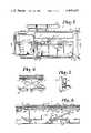
- FIG. 2is a side elevational view of the adjustable bed with head and foot sections in a first movement position.
- FIG. 3is a side elevational view of the adjustable bed with head and foot sections in a second movement position.
- FIG. 4is a side elevational view of the adjustable bed with head and foot sections in a third movement position.
- FIG. 5is a top plan fragmentary view of the adjustable bed showing details thereof.
- FIG. 6is a fragmentary view of a foot section of the adjustable bed and showing an arrangement for raising a foot panel portion.
- FIG. 7is an enlarged fragmentary view of an adjustment motor means for tilting the head and foot sections.
- FIG. 8is a longitudinal sectional view of the adjustable bed taken along lines 8--8, FIG. 5.
- FIG. 9is an enlarged fragmentary view of the side arm of the bed.
- FIG. 10is an enlarged sectional view taken along lines 10--10, FIG. 9.
- FIG. 11is a greatly enlarged view of the pivot connection between the side arm and the bed.
- FIG. 12is a sectional view taken along lines 12--12, FIG. 11 and showing the side arm in a first rotational position.
- FIG. 13is a sectional view after FIG. 12 and showing the side arm pivot connection in a second rotational position.
- the reference numeral 1generally designates an adjustable bed embodying the present invention.
- the adjustable bed 1comprises a floor engaging frame 2 and a mattress support 3 having a head section 4, center section 5, and a foot section 6 pivotally interconnected. Foot rests 7 provide patient comfort and a foldable foot step arrangement 8 facilitates ease of entry and exit from the bed 1.
- Side arms 9are pivotally connected to opposite sides of the center section 5 and include rotation locking means at positions to provide support to confine a patient 10 on the bed and to selectively provide additional restive area.
- the frame 2is a stationary, ground engaging structure adapted to support the patient 10 and the mattress support 3 above the ground or floor surface.
- the frame 2includes a pair of parallel, longitudinally extending side rails 13 and 14 which are interconnected at the head of the frame by a laterally extending cross member 15.
- End posts 16are affixed to opposite ends of the side rails 13 and 14 and have wheels 17 pivotally affixed to lower ends thereof.
- the wheels 17are preferably provided with brakes 18 to selectively prevent inadvertent movement over the floor surface.
- Upright end members 19have open lower ends which telescope over the end posts 16 and have upper ends with hand holds 20 affixed thereto to facilitate movement of the bed 1, as when wheeling the bed from room to room and through corridors and the like for movement of the patient 10.
- Upper ends of the end members 19are preferably provided with spring loaded end caps 22 which depress to provide access to the open interior of the respective end member 19 for insertion of an overhead traction frame 23, FIG. 4.
- the traction frame 23has a lift mechanism 24 for exercise of the patient or to assist and ease the patient into and off of the bed.
- intravenous administration equipment supports(not shown) may be inserted in the end members 19.
- Transverse cross braces 26 and 27extend between the side rails 13 and 14 at medial locations for mounting the mattress support 3.
- a platform 29, FIG. 8,extends between the side rails 13 and 14 headwardly of the cross brace 27 for support of a battery pack means described below.
- each of the sections 4, 5 and 6 of the mattress support 3has a generally rectangular shape, and includes a rigid, peripheral frame 30, such as of angle beam elements with interconnected end and side members 31 and 32.
- a flat plate or sheet 33overlies each of the peripheral frames 30 and is attached thereto by suitable fasteners, and preferably by means which will not interfere with the comfort of the bed, such as welds disposed along the frame 30 on the interior side or bottom of the sheet 33.
- Each of the mattress sections 4, 5 and 6also includes a medial brace member 35 extending between the end members 31 of the respective frames 30.
- hold downs 37such as for restraining straps (not shown) to prevent harm to the patient are affixed to each of the side members 32 of the peripheral frame 30 of the head section 4 and the foot section 6.
- the adjacent end members 31 of adjoining sections 4, 5 and 6are reinforced by angle beams 39, FIG. 8, for additional structural rigidity.
- the angle beams 39are L-shaped in cross section and have one web disposed against the end member 31 and the other web contacting the bottom side of the flat plate or sheet 33 and extending along the end edge thereof.
- the adjacent frame end edges of the head section 4 and foot section 6are interconnected to the center section 5 by respective piano hinges 41.
- Outwardly extending hinge plates 42extend over a portion of the end of the flat plate or sheet 33 and have fasteners extending therethrough and securing the hinge plates 42 to the associated web portions of the angle beams 39.
- each lift means 50respectively extend between the frame 2 and the head and foot sections 4 and 6 for tilting the head and foot sections 4 and 6 with respect to the center section 5.
- each lift means 50includes a motor 51 rotatably driving a jack screw 52.
- the illustrated motor 51is operable in either rotational direction.
- One end of the helical jack screw 52is mounted in a transmission 53, FIG. 7 and is operably connected therewith whereby activation of the electric motor 51 rotates the screw 52.
- the other end of the screw 52is threadably connected in an elongate sleeve member 54 having a plurality of anti-friction balls mounted on the interior portion thereof which engage the root of the screw 52 for smooth, secure engagement therewith.
- Rotation of the screw 52 in one directionpulls the sleeve 54 convergingly toward the motor 51, and rotation of the screw in the opposite direction pushes the sleeve divergingly apart from the motor.
- Pin and clevis hinge connections 55 respectively at opposite ends of the lift means 50connect the motor 51 to the respective cross brace 26 or 27 and the end of the sleeve member 54 to the frame brace member 35.
- operation of the respective lift means 50 at the head and foot sections 4 and 6causes same to pivot about the respective hinges 41 and move either upwardly or downwardly as selected.
- Each motor 51 and transmission 53include internal braking means whereby the jack screw 52 is nonrotatable in the transmission 53 except when the motor 51 is actuated.
- Each of the motors 51is electrically connected with a circuit arrangement for selectively activating each of the motors and controlling the direction of rotation thereof. Preferably, each motor is activated by current of 12 volts DC.
- a hand held switching controller 57is provided for operation of the motors 51 and has push button switches 58 therein for manipulation.
- a battery pack 60is positioned on one end of the platform 29 and connected by suitable circuitry to a battery charger. Switches activated by the controller 57 route electricity to the motors 51 for activation thereof.
- An outlet socket associated with the battery pack 60permits battery powered operation of life support systems such as resuscitators and the like.
- a diagnostic indicator panel in a battery pack cover member 61provides indication of battery charging and battery low voltage levels and additionally may include a buzzer for emission of a tone to indicate inadvertent disconnection of the battery pack 60 from a wall socket. If life support equipment, such as a resuscitator has electrical circuit lines thereof routed through the battery pack 60, such a buzzer would announce disconnection from the building power supply.
- panel members 63 of X-ray passive materialsuch as wood particle board are mounted in overlying relation to the respective head, center and foot sections 4, 5 and 6 and positioned a distance thereabove by spacers 64, thereby creating a cavity 65 between the panel members 63 and the associated section 4, 5 or 6.
- the spacers 64are arranged to provide unimpeded access to the cavity 65 for insertion of X-ray film material such as cassettes (not shown) for X-ray examination of thoracic, abdominal and leg regions.
- Expansible spacers 67are positioned between the panel member 63 and the underlying foot section 6 to permit elevated positioning of the patient's legs.
- the expansible spacers 67include leg members 68 and 69 fixed together at a pivot 70 in a scissor jack arrangement.
- a lower end 71 of the leg 68 and an upper end 72 of the leg 69are pivotally connected at fixed locations respectively to the foot section plate or sheet 33 and the panel member 63.
- An upper end 74 of the leg 68is pivotally connected in a sliding hinge 75 to the lower surface of the panel member 63.
- a lower end 76 of the leg 69has a roller 77 mounted thereon.
- the roller 77is selectively engageable with a stop block 79 normally in the path of travel of the roller 77.
- the stop block 79has an inclined ramp surface 80 on an upper portion thereof.
- the panel member 63 of the foot section 6is grasped and pulled upwardly, urging the roller 77 over the ramp surface 80. The panel member 63 is then released so that the roller 77 rolls toward and engages the stop block 79 to prevent further movement, thereby positioning the panel member 63 in an upward or extended position.
- the panel member 63is merely grasped and tilted to the left, FIG. 6, to draw the roller 77 upwardly and over the stop block 79 whereupon the panel member 63 can be lowered.
- the foot rests 7are provided for comfort of the patient 10 when the foot section 6 is in a downwardly tilted position, FIGS. 3 and 4.
- the foot rests 7include a support structure 82 and rotatable foot members 83.
- the support structure 82has a cross bar 84 extending transversely underneath the foot section 7 and arm members 85 connected to opposite ends thereof and extending upwardly of the panel member 63 and any mattress and placed thereon.
- Respective pins 86extending upwardly from the arm members 85 provide a rotatable connection for the foot members 83 which are in the form of plates and have an upholstered surface for comfort.
- the foot members 83are swingable on the pins 86 from a position over the foot section 6 to a stowed position aligned longitudinally forwardly or rearwardly with the bed.
- the foot rests 7are adjustable longitudinally on the foot section 6 to adapt to the length of a particular patient 10 and in the illustrated example, have a spring loaded engagement pin 87 with a pawl end (not shown) extending through the lower portion of each arm member 85 and engageable with a selected one of a series of apertures 88 in the side members 32 of the frame 30 of the foot section 6.
- the spring loaded engagement pins 87 of each arm member 85are grasped and pulled outwardly and the foot rests 7 slid toward the head or foot end as necessary. Once properly positioned, the engagement pins 87 are released to snap into apertures generally aligned thereunder and thereby lock the foot rests 7 into position.
- the foldable foot step arrangement 8is affixed to the end of the foot section 6 to facilitate entry and exit of the patient 10 from the bed 1.
- the step arrangement 8comprises a hingedly interconnected parallelogram frame arrangement which 8 automatically extends and stows as the foot section 6 is lowered and raised, FIGS. 2, 3 and 4.
- the side arms 9are positioned on opposite sides of the center section 5 and are rotatable toward and away from the center section 5 for purposes later described.
- the side armseach include spaced arm members 95 and 96 respectively having a lower end 97 and an upper or remote end 98 with the lower end 97 having a pivotal connection 99 to the center section 5.
- the arm lower end 97is bifurcated and forms a yoke structure with spaced bushings 100 and 101 connected thereto.
- the bushings 100 and 101straddle a bearing housing 103 affixed to a tang 104 projecting from the peripheral frame side member 32.
- the bearing housing 103is substantially cylindrical in shape and has an outer surface 106 and an interior bore 107 through the cylindrical axis thereof.
- Transverse grooves 109 and 110extend the length of the bearing housing 103 at approximately 35 degrees and 80 degrees lines of radius respectively from a vertical line extended through the axis of the bearing housing 103.
- Each of the grooves 109 and 110includes a flat bottom portion 112 and opposite, steep wall portions 113 providing an interior abutment edge between the bottom portion 112 and each wall portion 113.
- a pivot pin 115extends through the aligned bushings 100 and 101 and the bearing housing 103, thereby pivotally connecting the respective arm members 95 and 96 to the center section 5 for rotation about a longitudinal axis aligned with the length direction of the bed 1 and toward and away from the bed side.
- the yoke or bifurcation inlet 116includes an upper portion 117 and aligned bores extend through the arm end portions disposed from the bushings 100 and 101.
- the arm members 95 and 96each include catch arms 119 comprising elongate, relatively flat bars of sturdy material, such as steel, having one end portion 120 receivable in a selected one of the grooves 109 or 110 and an upper end portion 121 to provide a lever for moving the end portion 120 into and out of engagement in the selected groove 109 or 110.
- An intermediate portion 122 of the catch arm 119has a cylindrical bushing 123 fixed thereto, as by welding, with the bushing 123 having a through bore 124.
- a pivot pin 125extends through the bifurcated catch arm ends at the inlet upper portion 117 and through the bushing bore 124 to hingedly connect the catch arm 119 to the arm member 95 or 96.
- the catch arm 119extends substantially radially to clear a portion of the arm member at the top of the bifurcation inlet 116 and then curves to substantially parallel, yet slightly diverge from the associated the arm member 95 or 96, FIG. 10.
- a biasing membersuch as a coil spring 127, has one end received in a recess in the arms 95 and 96 and the other end free to engage the surface of the catch arm 119, FIG. 10, to urge the catch arm end portion 120 into engagement with a selected groove 109 or 110.
- a cross bar 128extends between the upper end portions 121.
- a side arm rail 130is attached to the remote ends 98 of the arm members 95 and 96 to provide a comfortable confining and resting surface for the patient 10.
- the side arm rail 130is an elongate, continuous loop of tubular material affixed, as by welding, to the upper or remote ends 98.
- the cross bar 128is grasped and pulled or pushed toward the bed and the side arm rail 130 is grasped and manipulated to rotate the side arm arrangement 9 in the desired direction.
- the arm members 95 and 96can be swung to a straight up or upright position and the catch arm end portion 120 received in the groove 109 to lock the side arm arrangement 9 at the upright position to confine a patient 10 on the bed 1.
- the processcan be repeated and the catch arm end portion 120 engaged in the groove 110, thereby affixing the side arm arrangement 9 at an outwardly swung position, FIGS. 1, 10 and 13 in approximately 45 degree relationship.
- a two-piece mattressis emplaced and has a combination center and head section mattress 132 and a foot section mattress 134.
- a bolster 135 of triangular cross sectionis emplaced in the open area created by the side arms 9 in the outwardly swung position, FIG. 1, to provide additional restive area and support for the patient 10. Because of the great bulk of the morbidly obese patient and particularly the great width in the hip area of some morbidly obese women, the additional space or restive area acquired by affixing the side arms 9 at the outwardly swung position is of great benefit to provide comfort for the patient.
- the adjustable bed 1has standard size transverse dimensions to accomodate passage through a normal width hospital door and the bed cannot normally pass therethrough with the side arms 9 in the outwardly swung position.
- the bolster 135is simply lifted out and the side arm 9 swung to the upright position, FIG. 2, thereby providing confining support for the patient during movement and transport through corridors to various medical treatment rooms and the like.
Landscapes
- Health & Medical Sciences (AREA)
- Nursing (AREA)
- Life Sciences & Earth Sciences (AREA)
- Animal Behavior & Ethology (AREA)
- General Health & Medical Sciences (AREA)
- Public Health (AREA)
- Veterinary Medicine (AREA)
- Invalid Beds And Related Equipment (AREA)
Abstract
Description
Claims (10)
Applications Claiming Priority (1)
| Application Number | Priority Date | Filing Date | Title |
|---|---|---|---|
| US06/231,175US4389134A (en) | 1980-03-17 | 1981-02-03 | Coupling of a tube to a ring member |
Publications (1)
| Publication Number | Publication Date |
|---|---|
| US4409695Atrue US4409695A (en) | 1983-10-18 |
Family
ID=22868053
Family Applications (1)
| Application Number | Title | Priority Date | Filing Date |
|---|---|---|---|
| US06/281,175Expired - LifetimeUS4409695A (en) | 1981-02-03 | 1981-07-07 | Adjustable bed for morbidly obese patients |
Country Status (1)
| Country | Link |
|---|---|
| US (1) | US4409695A (en) |
Cited By (90)
| Publication number | Priority date | Publication date | Assignee | Title |
|---|---|---|---|---|
| US4805249A (en)* | 1986-09-19 | 1989-02-21 | Pulukadang Freddy Usman | Rehabilitation bed |
| US4847929A (en)* | 1986-12-02 | 1989-07-18 | Milenko Pupovic | Bed with adjustable positions |
| US4949410A (en)* | 1988-03-11 | 1990-08-21 | Hausted, Inc. | Guard rail for patient transport apparatus hospital beds and the like |
| FR2654334A1 (en)* | 1989-11-10 | 1991-05-17 | Ecole Nat Sup Creation Ind | DEVICE FOR A MULTIFUNCTIONAL MEDICAL BED. |
| US5208928A (en)* | 1991-09-20 | 1993-05-11 | Midmark Corporation | Plastic surgery table |
| US5279010A (en)* | 1988-03-23 | 1994-01-18 | American Life Support Technology, Inc. | Patient care system |
| US5342114A (en)* | 1992-02-03 | 1994-08-30 | Burke Olive L | Convertible rolling chair and changing table for adult |
| US5682631A (en)* | 1995-08-04 | 1997-11-04 | Hill-Rom, Inc. | Bed having a reduced-shear pivot and step deck combination |
| US5715548A (en)* | 1994-01-25 | 1998-02-10 | Hill-Rom, Inc. | Chair bed |
| WO1998022071A1 (en)* | 1996-11-18 | 1998-05-28 | Kinetic Concepts, Inc. | Bariatric treatment system and relating methods |
| US5790997A (en)* | 1995-08-04 | 1998-08-11 | Hill-Rom Inc. | Table/chair egress device |
| WO1999000099A3 (en)* | 1997-06-26 | 1999-03-18 | Hill Rom Co Inc | Bariatric bed |
| US5987666A (en)* | 1999-03-15 | 1999-11-23 | St. Luke Foundation | Gap-filling pad disposable between a mattress and a bed rail |
| US6000076A (en)* | 1996-10-23 | 1999-12-14 | Hill-Rom, Inc. | Procedural stretcher recline controls |
| US6212714B1 (en) | 1995-01-03 | 2001-04-10 | Hill-Rom, Inc. | Hospital bed and mattress having a retracting foot section |
| US6212713B1 (en) | 1999-08-09 | 2001-04-10 | Midmark Corporation | Examination table with sliding back section |
| US6345402B1 (en)* | 1997-09-09 | 2002-02-12 | Hill-Rom Services, Inc. | Hinged panels for a thermal support apparatus |
| US6357065B1 (en)* | 1999-11-15 | 2002-03-19 | Mellen Air Manufacturing, Inc. | Variable width bariatric modularbed |
| US6427264B1 (en) | 1999-03-19 | 2002-08-06 | Hill-Rom Services, Inc. | Gap filler for bed |
| US6516479B1 (en)* | 2000-06-02 | 2003-02-11 | Burke Mobility Products, Inc. | Foldable rehabilitation bed for accommodating an obese person |
| US6536056B1 (en) | 1996-11-18 | 2003-03-25 | John H. Vrzalik | Bariatric treatment system and related methods |
| US20030093863A1 (en)* | 2001-11-17 | 2003-05-22 | Medi-Plinth Healthcare Group Ltd. | Bed |
| US6611979B2 (en) | 1997-09-23 | 2003-09-02 | Hill-Rom Services, Inc. | Mattress having a retractable foot section |
| US6668408B2 (en) | 1988-03-23 | 2003-12-30 | Hill-Rom Services, Inc. | Patient care system |
| US6694549B2 (en) | 2001-04-20 | 2004-02-24 | Hill-Rom Services, Inc. | Bed frame with reduced-shear pivot |
| US6694557B1 (en) | 1997-06-26 | 2004-02-24 | Hill-Rom Services, Inc. | Bariatric bed |
| US6711761B2 (en) | 2000-10-04 | 2004-03-30 | Northpole, Ltd. | Inclining bed with collapsible frame |
| US20040154103A1 (en)* | 2001-01-19 | 2004-08-12 | Ernst Bock | Bed, particulary hospital and/or nursing bed |
| US6820293B2 (en) | 2002-09-26 | 2004-11-23 | Hill-Rom Services, Inc. | Bed siderail pad apparatus |
| US20050000020A1 (en)* | 2003-02-10 | 2005-01-06 | Ferdinand Schermel | Multi-position reclining bed with desk |
| US20050022294A1 (en)* | 2003-08-01 | 2005-02-03 | Javier Garza Laguera Garza | Toilet for obese persons |
| US20050071921A1 (en)* | 1999-10-15 | 2005-04-07 | Hill-Rom Services, Inc. | Siderail pad for hospital bed |
| US20050204473A1 (en)* | 2004-03-03 | 2005-09-22 | Sebastian Maier | Imaging tomography apparatus having an attached patient support with a movable backrest |
| US20050225107A1 (en)* | 2002-10-18 | 2005-10-13 | Mitchell Donald F | Bariatric gurney and process |
| US20050229321A1 (en)* | 1996-11-18 | 2005-10-20 | Kci Licensing, Inc. | Bariatric treatment system and related methods |
| US6978501B2 (en)* | 1995-01-31 | 2005-12-27 | Kci Licensing, Inc. | Bariatric bed apparatus and methods |
| US20060000021A1 (en)* | 2002-05-17 | 2006-01-05 | Stephen Hayes | Profiling bed |
| US20060021142A1 (en)* | 2004-07-30 | 2006-02-02 | Hornbach David W | Patient support having powered adjustable width |
| US20060026762A1 (en)* | 2004-07-28 | 2006-02-09 | Hornbach David M | Hospital bed |
| US7017208B2 (en) | 1995-08-04 | 2006-03-28 | Hill-Rom Services, Inc. | Hospital bed |
| US7028352B2 (en) | 2001-08-22 | 2006-04-18 | Hill-Rom Services, Inc. | Apparatus and method for closing hospital bed gaps |
| US20060085914A1 (en)* | 2004-06-14 | 2006-04-27 | Steve Peterson | Adjustable bed for bariatric patients |
| US7073220B2 (en) | 2002-09-06 | 2006-07-11 | Hill-Rom Services, Inc. | Bed siderail having a latch |
| US20060168728A1 (en)* | 2002-12-26 | 2006-08-03 | Strobel Frederic W | Bariatric patient management system |
| US7100222B2 (en) | 2001-08-22 | 2006-09-05 | Hill-Rom Services, Inc. | Apparatus and method for mounting hospital bed accessories |
| US20060208552A1 (en)* | 2005-03-18 | 2006-09-21 | Broda Enterprises, Inc. | Laterally adjustable armrest assembly |
| US20060208554A1 (en)* | 2005-03-18 | 2006-09-21 | Broda Enterprises, Inc. | Backrest for bariatric chair |
| US20070000056A1 (en)* | 2005-06-29 | 2007-01-04 | Philip Ward | Stretcher |
| US7296312B2 (en) | 2002-09-06 | 2007-11-20 | Hill-Rom Services, Inc. | Hospital bed |
| US20080000028A1 (en)* | 2006-06-28 | 2008-01-03 | Stryker Corporation | Patient support |
| WO2007092526A3 (en)* | 2006-02-08 | 2008-06-26 | Hill Rom Services Inc | End panel for a patient-support apparatus |
| US7451506B2 (en) | 1995-08-04 | 2008-11-18 | Hil-Rom Services, Inc. | Bed having electrical communication network |
| US20090229051A1 (en)* | 2008-03-13 | 2009-09-17 | Hill-Rom Services, Inc. | Siderail assembly for a patient-support apparatus |
| US20100031441A1 (en)* | 2008-08-05 | 2010-02-11 | Pascal Guguin | Bed with a Lateral Barrier Having a Tilt Feature |
| US7676862B2 (en) | 2004-09-13 | 2010-03-16 | Kreg Medical, Inc. | Siderail for hospital bed |
| US7743441B2 (en) | 2004-09-13 | 2010-06-29 | Kreg Therapeutics, Inc. | Expandable width bed |
| US7757318B2 (en) | 2004-09-13 | 2010-07-20 | Kreg Therapeutics, Inc. | Mattress for a hospital bed |
| US20100205740A1 (en)* | 2004-07-30 | 2010-08-19 | Tybinkowski Andrew P | X-ray transparent bed and gurney extender for use with mobile computerized tomography (ct) imaging systems |
| US7779494B2 (en) | 2004-09-13 | 2010-08-24 | Kreg Therapeutics, Inc. | Bed having fixed length foot deck |
| EP2206485A3 (en)* | 1996-11-18 | 2010-09-08 | Kinetic Concepts, Inc. | Bariatric treatment system |
| US7917978B2 (en) | 2004-03-12 | 2011-04-05 | Hill-Rom Services, Inc. | Variable height siderail for a bed |
| US7930778B2 (en) | 2007-12-07 | 2011-04-26 | Hill-Rom Services, Inc. | Pinch-preventing unit for bed guardrail |
| US20110143898A1 (en)* | 2009-12-14 | 2011-06-16 | Hill-Rom Services, Inc. | Patient support apparatuses with exercise functionalities |
| US8104122B2 (en) | 2005-12-19 | 2012-01-31 | Hill-Rom Services, Inc. | Patient support having an extendable foot section |
| USRE43155E1 (en)* | 1995-01-03 | 2012-02-07 | Hill-Rom Services, Inc. | Hospital bed and mattress having a retractable foot section |
| US20120226202A1 (en)* | 2011-03-02 | 2012-09-06 | Wright Wellness Solutions, Inc. | Passive Mobility Exercise and Range-of-Motion Bed Apparatus |
| US8341778B2 (en) | 2011-02-07 | 2013-01-01 | Hill-Rom Services, Inc. | Bed gap filler and footboard pad |
| US8474076B2 (en) | 2011-02-04 | 2013-07-02 | Hill-Rom Services, Inc. | Adjustable foot section for a patient support apparatus |
| EP2644177A1 (en)* | 2012-03-29 | 2013-10-02 | Hill-Rom Services, Inc. | Footboard Egress Design |
| US8864205B2 (en) | 2006-06-28 | 2014-10-21 | Stryker Corporation | Patient support with wireless data and/or energy transfer |
| US9038218B1 (en) | 2014-01-15 | 2015-05-26 | Hill-Rom Services, Inc. | Person support apparatuses with selectively coupled foot sections |
| US9060619B2 (en) | 2010-07-09 | 2015-06-23 | Hill-Rom Services, Inc. | Variable height siderail |
| US9089459B2 (en) | 2013-11-18 | 2015-07-28 | Völker GmbH | Person support apparatus |
| US9101517B2 (en) | 2010-08-30 | 2015-08-11 | Hill-Rom Services, Inc. | Patient-support apparatus with a configurable siderail |
| US9119753B2 (en) | 2008-06-27 | 2015-09-01 | Kreg Medical, Inc. | Bed with modified foot deck |
| US9132051B2 (en) | 2014-01-15 | 2015-09-15 | Hill-Rom Services, Inc. | Person support apparatuses with exercise functionalities |
| US9265677B2 (en) | 2009-12-23 | 2016-02-23 | Piedmont 361, Llc | Hospital chair beds with stowable stand-assist supports |
| EP3156025A1 (en)* | 2015-10-14 | 2017-04-19 | Palfinger Tail Lifts GmbH | Lifting platform |
| US9763840B2 (en) | 2013-02-05 | 2017-09-19 | Hill-Rom Services, Inc. | Bed having rack and pinion powered width expansion |
| US9931277B2 (en) | 2015-06-11 | 2018-04-03 | Zahra Miswak QAYSI | Drug and fluid dispenser |
| CN109528438A (en)* | 2019-01-24 | 2019-03-29 | 贾韩静 | A kind of multi-link fracture rehabilitation equipment |
| US10426680B2 (en) | 2015-07-31 | 2019-10-01 | Hill-Rom Services, Inc. | Air bladder control of mattress/frame width expansion |
| CN110478188A (en)* | 2019-08-16 | 2019-11-22 | 南阳市中心医院 | One kind is based on joint surgery health shield treatment seat |
| US10874567B2 (en) | 2014-03-11 | 2020-12-29 | Hill-Rom Services, Inc. | Patient bed having footboard pedal apparatus for physical therapy |
| US10898000B2 (en) | 2018-07-26 | 2021-01-26 | United Metal Fabricators, Inc. | Leg extension for procedure chair |
| CN112891140A (en)* | 2021-01-25 | 2021-06-04 | 黑龙江中医药大学 | Medical intensive care unit ICU assists rehabilitation device |
| US11090214B2 (en) | 2018-08-06 | 2021-08-17 | United Metal Fabricators, Inc. | Leg support assembly for medical examination device |
| US11259975B2 (en)* | 2018-10-13 | 2022-03-01 | Breanne O'Leary | Apparatus providing extension of a surgical table width allowing adaptation to the parameters of the specific patient |
| US11963918B2 (en) | 2020-04-20 | 2024-04-23 | Hill-Rom Services, Inc. | Patient bed having active motion exercise |
| US12150908B2 (en) | 2014-04-18 | 2024-11-26 | Kreg Medical, Inc. | Patient support with stand-up and sit features |
Citations (11)
| Publication number | Priority date | Publication date | Assignee | Title |
|---|---|---|---|---|
| US238282A (en)* | 1881-03-01 | Bedstead attachment | ||
| US859911A (en)* | 1906-11-28 | 1907-07-16 | Katherine D Bowling | Bedstead. |
| US1279120A (en)* | 1916-12-05 | 1918-09-17 | John H Kellogg | Electrotherapeutical chair. |
| GB523334A (en)* | 1938-12-31 | 1940-07-11 | Albert Phillips Ltd | Improvements in or relating to bedsteads |
| US3021889A (en)* | 1960-01-25 | 1962-02-20 | Institutional Ind Inc | Foldable wheel chair |
| US3213469A (en)* | 1961-12-04 | 1965-10-26 | Beeman Harriet Howes | Hospital bed |
| US3284126A (en)* | 1964-05-14 | 1966-11-08 | Salvatore J Piazza | Bed-wheelchair |
| US3293667A (en)* | 1965-10-20 | 1966-12-27 | John F Ohrberg | Adjustable, ambulating, tilting and reclining bed |
| US3373453A (en)* | 1966-09-13 | 1968-03-19 | Goodman Robert | Vertically adjustable bed |
| DE2321968A1 (en)* | 1973-05-02 | 1974-11-14 | Arnold L & C | INTENSIVE CARE BED |
| US4038709A (en)* | 1975-12-24 | 1977-08-02 | Kerwit Medical Products, Inc. | Dual hydraulic hospital bed |
- 1981
- 1981-07-07USUS06/281,175patent/US4409695A/ennot_activeExpired - Lifetime
Patent Citations (11)
| Publication number | Priority date | Publication date | Assignee | Title |
|---|---|---|---|---|
| US238282A (en)* | 1881-03-01 | Bedstead attachment | ||
| US859911A (en)* | 1906-11-28 | 1907-07-16 | Katherine D Bowling | Bedstead. |
| US1279120A (en)* | 1916-12-05 | 1918-09-17 | John H Kellogg | Electrotherapeutical chair. |
| GB523334A (en)* | 1938-12-31 | 1940-07-11 | Albert Phillips Ltd | Improvements in or relating to bedsteads |
| US3021889A (en)* | 1960-01-25 | 1962-02-20 | Institutional Ind Inc | Foldable wheel chair |
| US3213469A (en)* | 1961-12-04 | 1965-10-26 | Beeman Harriet Howes | Hospital bed |
| US3284126A (en)* | 1964-05-14 | 1966-11-08 | Salvatore J Piazza | Bed-wheelchair |
| US3293667A (en)* | 1965-10-20 | 1966-12-27 | John F Ohrberg | Adjustable, ambulating, tilting and reclining bed |
| US3373453A (en)* | 1966-09-13 | 1968-03-19 | Goodman Robert | Vertically adjustable bed |
| DE2321968A1 (en)* | 1973-05-02 | 1974-11-14 | Arnold L & C | INTENSIVE CARE BED |
| US4038709A (en)* | 1975-12-24 | 1977-08-02 | Kerwit Medical Products, Inc. | Dual hydraulic hospital bed |
Cited By (186)
| Publication number | Priority date | Publication date | Assignee | Title |
|---|---|---|---|---|
| US4805249A (en)* | 1986-09-19 | 1989-02-21 | Pulukadang Freddy Usman | Rehabilitation bed |
| US4847929A (en)* | 1986-12-02 | 1989-07-18 | Milenko Pupovic | Bed with adjustable positions |
| US4949410A (en)* | 1988-03-11 | 1990-08-21 | Hausted, Inc. | Guard rail for patient transport apparatus hospital beds and the like |
| US6941598B2 (en)* | 1988-03-23 | 2005-09-13 | Hill-Rom Services, Inc. | Patient care system |
| US6668408B2 (en) | 1988-03-23 | 2003-12-30 | Hill-Rom Services, Inc. | Patient care system |
| US5279010A (en)* | 1988-03-23 | 1994-01-18 | American Life Support Technology, Inc. | Patient care system |
| RU2128479C1 (en)* | 1988-03-23 | 1999-04-10 | Хилл-Ром, Инк. | Patient supporting device (variants) and method of supporting the man's body on mattress |
| FR2654334A1 (en)* | 1989-11-10 | 1991-05-17 | Ecole Nat Sup Creation Ind | DEVICE FOR A MULTIFUNCTIONAL MEDICAL BED. |
| WO1991007157A1 (en)* | 1989-11-10 | 1991-05-30 | Didier Couineau | Device for a multifunction medical bed |
| US5208928A (en)* | 1991-09-20 | 1993-05-11 | Midmark Corporation | Plastic surgery table |
| US5342114A (en)* | 1992-02-03 | 1994-08-30 | Burke Olive L | Convertible rolling chair and changing table for adult |
| US6336235B1 (en) | 1994-01-25 | 2002-01-08 | Hill-Rom Services, Inc. | Chair bed |
| US5715548A (en)* | 1994-01-25 | 1998-02-10 | Hill-Rom, Inc. | Chair bed |
| US6163903A (en)* | 1994-01-25 | 2000-12-26 | Hill-Rom Inc. | Chair bed |
| US20040221391A1 (en)* | 1995-01-03 | 2004-11-11 | Allen E. David | Hospital bed and matress having a retractable foot section |
| US7523515B2 (en) | 1995-01-03 | 2009-04-28 | Hill-Rom Services, Inc. | Hospital bed and mattress having a retractable foot section |
| US20060096030A1 (en)* | 1995-01-03 | 2006-05-11 | Allen E D | Hospital bed and mattress having a retractable foot section |
| US7216384B2 (en) | 1995-01-03 | 2007-05-15 | Hill-Rom Services, Inc. | Hospital bed and mattress having a retractable foot section |
| US6212714B1 (en) | 1995-01-03 | 2001-04-10 | Hill-Rom, Inc. | Hospital bed and mattress having a retracting foot section |
| US6684427B2 (en) | 1995-01-03 | 2004-02-03 | Hill-Rom Services, Inc. | Hospital bed and matress having a retractable foot section |
| US6496993B2 (en) | 1995-01-03 | 2002-12-24 | Hill-Rom Services, Inc. | Hospital bed and mattress having a retracting foot section |
| US7000272B2 (en)* | 1995-01-03 | 2006-02-21 | Hill-Rom Services, Inc. | Hospital bed and mattress having a retractable foot section |
| USRE43155E1 (en)* | 1995-01-03 | 2012-02-07 | Hill-Rom Services, Inc. | Hospital bed and mattress having a retractable foot section |
| US20080289107A1 (en)* | 1995-01-31 | 2008-11-27 | Kci Licensing, Inc. | Bariatric Bed Apparatus and Methods |
| US20060090261A1 (en)* | 1995-01-31 | 2006-05-04 | Kci Licensing, Inc. | Bariatric bed apparatus and methods |
| US6978501B2 (en)* | 1995-01-31 | 2005-12-27 | Kci Licensing, Inc. | Bariatric bed apparatus and methods |
| US7426760B2 (en)* | 1995-01-31 | 2008-09-23 | Kci Licensing, Inc. | Bariatric bed apparatus and methods |
| US7827632B2 (en) | 1995-01-31 | 2010-11-09 | Vrzalik John H | Bariatric bed apparatus and methods |
| US20100306921A1 (en)* | 1995-08-04 | 2010-12-09 | Kramer Kenneth L | Hospital bed |
| US20060168729A1 (en)* | 1995-08-04 | 2006-08-03 | Weismiller Matthew W | Hospital bed and mattress having extendable foot section |
| US8065764B2 (en) | 1995-08-04 | 2011-11-29 | Hill-Rom Services, Inc. | Hospital bed |
| US5682631A (en)* | 1995-08-04 | 1997-11-04 | Hill-Rom, Inc. | Bed having a reduced-shear pivot and step deck combination |
| US7480951B2 (en) | 1995-08-04 | 2009-01-27 | Hill-Rom Services, Inc. | Patient care bed with network |
| US7213279B2 (en) | 1995-08-04 | 2007-05-08 | Weismiller Matthew W | Hospital bed and mattress having extendable foot section |
| US8056165B2 (en) | 1995-08-04 | 2011-11-15 | Hill-Rom Services, Inc. | Inflatable mattress for a bed |
| US7237287B2 (en) | 1995-08-04 | 2007-07-03 | Hill-Rom Services, Inc. | Patient care bed with network |
| US20100306924A1 (en)* | 1995-08-04 | 2010-12-09 | Kummer Joseph A | Inflatable mattress for a bed |
| US20070180618A1 (en)* | 1995-08-04 | 2007-08-09 | Weismiller Matthew W | Patient care bed with network |
| US7451506B2 (en) | 1995-08-04 | 2008-11-18 | Hil-Rom Services, Inc. | Bed having electrical communication network |
| US20060150332A1 (en)* | 1995-08-04 | 2006-07-13 | Weismiller Matthew W | Patient care bed with network |
| US7802332B2 (en) | 1995-08-04 | 2010-09-28 | Hill-Rom Services, Inc. | Inflatable mattress for a bed |
| US7017208B2 (en) | 1995-08-04 | 2006-03-28 | Hill-Rom Services, Inc. | Hospital bed |
| US5790997A (en)* | 1995-08-04 | 1998-08-11 | Hill-Rom Inc. | Table/chair egress device |
| US7784128B2 (en) | 1995-08-04 | 2010-08-31 | Hill-Rom Services, Inc. | Hospital bed |
| US7568246B2 (en) | 1995-08-04 | 2009-08-04 | Hill-Rom Services, Inc. | Bed with a networked alarm |
| US8413274B2 (en) | 1995-08-04 | 2013-04-09 | Hill-Rom Services, Inc. | Hospital bed |
| US20090151073A1 (en)* | 1995-08-04 | 2009-06-18 | Kramer Kenneth L | Hospital bed |
| US20080052831A1 (en)* | 1995-08-04 | 2008-03-06 | Weismiller Matthew W | Bed with a networked alarm |
| US8286282B2 (en) | 1995-08-04 | 2012-10-16 | Hill-Rom Services, Inc. | Bed frame and mattress synchronous control |
| US20090064416A1 (en)* | 1995-08-04 | 2009-03-12 | Kummer Joseph A | Inflatable mattress for a bed |
| US6000076A (en)* | 1996-10-23 | 1999-12-14 | Hill-Rom, Inc. | Procedural stretcher recline controls |
| US6226816B1 (en) | 1996-10-23 | 2001-05-08 | Hill-Rom, Inc. | Procedural stretcher recline controls |
| US7346945B2 (en) | 1996-11-18 | 2008-03-25 | Kci Licensing, Inc. | Bariatric treatment system and related methods |
| US20030208847A1 (en)* | 1996-11-18 | 2003-11-13 | Kinetic Concepts, Inc. | Bariatric treatment system and related methods |
| US6536056B1 (en) | 1996-11-18 | 2003-03-25 | John H. Vrzalik | Bariatric treatment system and related methods |
| US20050229321A1 (en)* | 1996-11-18 | 2005-10-20 | Kci Licensing, Inc. | Bariatric treatment system and related methods |
| US6904631B2 (en) | 1996-11-18 | 2005-06-14 | Kci Licensing, Inc. | Bariatric treatment system and related methods |
| EP2206485A3 (en)* | 1996-11-18 | 2010-09-08 | Kinetic Concepts, Inc. | Bariatric treatment system |
| WO1998022071A1 (en)* | 1996-11-18 | 1998-05-28 | Kinetic Concepts, Inc. | Bariatric treatment system and relating methods |
| WO1999000099A3 (en)* | 1997-06-26 | 1999-03-18 | Hill Rom Co Inc | Bariatric bed |
| US6141806A (en)* | 1997-06-26 | 2000-11-07 | Hill-Rom, Inc. | Bariatric bed |
| US6694557B1 (en) | 1997-06-26 | 2004-02-24 | Hill-Rom Services, Inc. | Bariatric bed |
| US6345402B1 (en)* | 1997-09-09 | 2002-02-12 | Hill-Rom Services, Inc. | Hinged panels for a thermal support apparatus |
| US6611979B2 (en) | 1997-09-23 | 2003-09-02 | Hill-Rom Services, Inc. | Mattress having a retractable foot section |
| US5987666A (en)* | 1999-03-15 | 1999-11-23 | St. Luke Foundation | Gap-filling pad disposable between a mattress and a bed rail |
| US6427264B1 (en) | 1999-03-19 | 2002-08-06 | Hill-Rom Services, Inc. | Gap filler for bed |
| US6704954B2 (en) | 1999-03-19 | 2004-03-16 | Hill-Rom Services, Inc. | Gap filler for bed |
| US7107636B2 (en) | 1999-03-19 | 2006-09-19 | Hill-Rom Services, Inc. | Gap filler for bed |
| US6212713B1 (en) | 1999-08-09 | 2001-04-10 | Midmark Corporation | Examination table with sliding back section |
| US20050071921A1 (en)* | 1999-10-15 | 2005-04-07 | Hill-Rom Services, Inc. | Siderail pad for hospital bed |
| US6928673B2 (en) | 1999-10-15 | 2005-08-16 | Hill-Rom Services, Inc. | Siderail pad for hospital bed |
| US6357065B1 (en)* | 1999-11-15 | 2002-03-19 | Mellen Air Manufacturing, Inc. | Variable width bariatric modularbed |
| US6880189B2 (en) | 1999-12-29 | 2005-04-19 | Hill-Rom Services, Inc. | Patient support |
| US20040034936A1 (en)* | 1999-12-29 | 2004-02-26 | Hill-Rom Services, Inc. | Patient support |
| US7926131B2 (en) | 1999-12-29 | 2011-04-19 | Hill-Rom Services, Inc. | Hospital bed |
| US9009893B2 (en) | 1999-12-29 | 2015-04-21 | Hill-Rom Services, Inc. | Hospital bed |
| US10251797B2 (en) | 1999-12-29 | 2019-04-09 | Hill-Rom Services, Inc. | Hospital bed |
| US8151387B2 (en) | 1999-12-29 | 2012-04-10 | Hill-Rom Services, Inc. | Hospital bed frame |
| US6516479B1 (en)* | 2000-06-02 | 2003-02-11 | Burke Mobility Products, Inc. | Foldable rehabilitation bed for accommodating an obese person |
| US6711761B2 (en) | 2000-10-04 | 2004-03-30 | Northpole, Ltd. | Inclining bed with collapsible frame |
| US20040154103A1 (en)* | 2001-01-19 | 2004-08-12 | Ernst Bock | Bed, particulary hospital and/or nursing bed |
| US20040158923A1 (en)* | 2001-04-20 | 2004-08-19 | Hill-Rom Services, Inc. | Patient support having a siderail |
| US6694549B2 (en) | 2001-04-20 | 2004-02-24 | Hill-Rom Services, Inc. | Bed frame with reduced-shear pivot |
| US7591034B2 (en) | 2001-08-22 | 2009-09-22 | Hill-Rom Services, Inc. | Apparatus and method for closing hospital bed gaps |
| US7028352B2 (en) | 2001-08-22 | 2006-04-18 | Hill-Rom Services, Inc. | Apparatus and method for closing hospital bed gaps |
| US7100222B2 (en) | 2001-08-22 | 2006-09-05 | Hill-Rom Services, Inc. | Apparatus and method for mounting hospital bed accessories |
| US7293305B2 (en) | 2001-08-22 | 2007-11-13 | Hill-Rom Services, Inc. | Apparatus and method for mounting hospital bed accessories |
| US7788747B2 (en) | 2001-08-22 | 2010-09-07 | Hill-Rom Services, Inc. | Apparatus and method for closing hospital bed gaps |
| US7222377B2 (en) | 2001-08-22 | 2007-05-29 | Hill-Rom Services, Inc. | Apparatus and method for closing hospital bed gaps |
| US6912746B2 (en) | 2001-11-17 | 2005-07-05 | Medi-Plinth Limited | Bed |
| GB2383263B (en)* | 2001-11-17 | 2005-11-16 | Medi Plinth Healthcare Group L | Bed |
| EP1312330A3 (en)* | 2001-11-17 | 2003-10-08 | Medi-Plinth Healthcare Group Limited | Bed |
| US20030093863A1 (en)* | 2001-11-17 | 2003-05-22 | Medi-Plinth Healthcare Group Ltd. | Bed |
| US20060000021A1 (en)* | 2002-05-17 | 2006-01-05 | Stephen Hayes | Profiling bed |
| US7441291B2 (en)* | 2002-05-17 | 2008-10-28 | Huntleigh Technology Limited | Profiling bed |
| US7506390B2 (en) | 2002-09-06 | 2009-03-24 | Hill-Rom Services, Inc. | Patient support apparatus having controller area network |
| US7703158B2 (en) | 2002-09-06 | 2010-04-27 | Hill-Rom Services, Inc. | Patient support apparatus having a diagnostic system |
| US7520006B2 (en) | 2002-09-06 | 2009-04-21 | Hill-Rom Services, Inc. | Hospital bed including moveable foot portion |
| US7296312B2 (en) | 2002-09-06 | 2007-11-20 | Hill-Rom Services, Inc. | Hospital bed |
| US7073220B2 (en) | 2002-09-06 | 2006-07-11 | Hill-Rom Services, Inc. | Bed siderail having a latch |
| US7669263B2 (en) | 2002-09-06 | 2010-03-02 | Hill-Rom Services, Inc. | Mattress assembly including adjustable length foot |
| USRE43532E1 (en) | 2002-09-06 | 2012-07-24 | Hill-Rom Services, Inc. | Hospital bed |
| US7406731B2 (en) | 2002-09-06 | 2008-08-05 | Holl-Rom Services, Inc. | Hospital bed |
| US6820293B2 (en) | 2002-09-26 | 2004-11-23 | Hill-Rom Services, Inc. | Bed siderail pad apparatus |
| US20050225107A1 (en)* | 2002-10-18 | 2005-10-13 | Mitchell Donald F | Bariatric gurney and process |
| US7111340B2 (en)* | 2002-10-18 | 2006-09-26 | Godby Enterprises, Llc | Bariatric gurney and process |
| US7568247B2 (en)* | 2002-12-26 | 2009-08-04 | Gendron, Inc. | Bariatric patient management system |
| US20060168728A1 (en)* | 2002-12-26 | 2006-08-03 | Strobel Frederic W | Bariatric patient management system |
| US8615828B2 (en)* | 2003-02-10 | 2013-12-31 | Ferdinand Schermel | Multi-position reclining bed |
| US20050000020A1 (en)* | 2003-02-10 | 2005-01-06 | Ferdinand Schermel | Multi-position reclining bed with desk |
| US20050022294A1 (en)* | 2003-08-01 | 2005-02-03 | Javier Garza Laguera Garza | Toilet for obese persons |
| US20050204473A1 (en)* | 2004-03-03 | 2005-09-22 | Sebastian Maier | Imaging tomography apparatus having an attached patient support with a movable backrest |
| US7151816B2 (en)* | 2004-03-03 | 2006-12-19 | Siemens Aktiengesellschaft | Imaging tomography apparatus having an attached patient support with a movable backrest |
| US7917978B2 (en) | 2004-03-12 | 2011-04-05 | Hill-Rom Services, Inc. | Variable height siderail for a bed |
| US20060085914A1 (en)* | 2004-06-14 | 2006-04-27 | Steve Peterson | Adjustable bed for bariatric patients |
| US20110191959A1 (en)* | 2004-07-28 | 2011-08-11 | Hornbach David W | Hospital bed lift and braking mechanisms |
| US8621690B2 (en) | 2004-07-28 | 2014-01-07 | Hill-Rom Services, Inc. | Hospital bed lift and braking mechanisms |
| US7886380B2 (en) | 2004-07-28 | 2011-02-15 | Hill-Rom Services, Inc. | Hospital bed |
| US20060026762A1 (en)* | 2004-07-28 | 2006-02-09 | Hornbach David M | Hospital bed |
| US20100205740A1 (en)* | 2004-07-30 | 2010-08-19 | Tybinkowski Andrew P | X-ray transparent bed and gurney extender for use with mobile computerized tomography (ct) imaging systems |
| US7406729B2 (en) | 2004-07-30 | 2008-08-05 | Hill-Rom Services, Inc. | Patient support having powered adjustable width |
| US20080282472A1 (en)* | 2004-07-30 | 2008-11-20 | Hornbach David W | Patient support having powered adjustable width |
| US7730562B2 (en) | 2004-07-30 | 2010-06-08 | Hill-Rom Services, Inc. | Patient support having powered adjustable width |
| US20060021142A1 (en)* | 2004-07-30 | 2006-02-02 | Hornbach David W | Patient support having powered adjustable width |
| US8905637B2 (en)* | 2004-07-30 | 2014-12-09 | Neurologica Corp. | X-ray transparent bed and gurney extender for use with mobile computerized tomography (CT) imaging systems |
| US7743441B2 (en) | 2004-09-13 | 2010-06-29 | Kreg Therapeutics, Inc. | Expandable width bed |
| US7676862B2 (en) | 2004-09-13 | 2010-03-16 | Kreg Medical, Inc. | Siderail for hospital bed |
| US7779494B2 (en) | 2004-09-13 | 2010-08-24 | Kreg Therapeutics, Inc. | Bed having fixed length foot deck |
| US7757318B2 (en) | 2004-09-13 | 2010-07-20 | Kreg Therapeutics, Inc. | Mattress for a hospital bed |
| US8069514B2 (en) | 2004-09-13 | 2011-12-06 | Kreg Medical, Inc. | Expandable width bed |
| US8056160B2 (en) | 2004-09-13 | 2011-11-15 | Kreg Medical, Inc. | Siderail for hospital bed |
| US20060208554A1 (en)* | 2005-03-18 | 2006-09-21 | Broda Enterprises, Inc. | Backrest for bariatric chair |
| US20060208552A1 (en)* | 2005-03-18 | 2006-09-21 | Broda Enterprises, Inc. | Laterally adjustable armrest assembly |
| US7676861B2 (en) | 2005-06-29 | 2010-03-16 | Ferno (Uk) Limited | Stretcher |
| US20070000056A1 (en)* | 2005-06-29 | 2007-01-04 | Philip Ward | Stretcher |
| US8104122B2 (en) | 2005-12-19 | 2012-01-31 | Hill-Rom Services, Inc. | Patient support having an extendable foot section |
| WO2007092526A3 (en)* | 2006-02-08 | 2008-06-26 | Hill Rom Services Inc | End panel for a patient-support apparatus |
| US7934276B2 (en) | 2006-02-08 | 2011-05-03 | Hill-Rom Services, Inc. | End panel for a patient-support apparatus |
| US12383450B2 (en) | 2006-06-28 | 2025-08-12 | Stryker Corporation | Patient support with energy transfer |
| US10561551B2 (en) | 2006-06-28 | 2020-02-18 | Stryker Corporation | Patient support with energy transfer |
| US11793699B2 (en) | 2006-06-28 | 2023-10-24 | Stryker Corporation | Patient support with energy transfer |
| US20080000028A1 (en)* | 2006-06-28 | 2008-01-03 | Stryker Corporation | Patient support |
| US8056163B2 (en) | 2006-06-28 | 2011-11-15 | Stryker Corporation | Patient support |
| US8864205B2 (en) | 2006-06-28 | 2014-10-21 | Stryker Corporation | Patient support with wireless data and/or energy transfer |
| US7930778B2 (en) | 2007-12-07 | 2011-04-26 | Hill-Rom Services, Inc. | Pinch-preventing unit for bed guardrail |
| US20090229051A1 (en)* | 2008-03-13 | 2009-09-17 | Hill-Rom Services, Inc. | Siderail assembly for a patient-support apparatus |
| US8239986B2 (en) | 2008-03-13 | 2012-08-14 | Hill-Rom Services, Inc. | Siderail assembly for a patient-support apparatus |
| US12208041B2 (en) | 2008-06-27 | 2025-01-28 | Kreg Medical, Inc. | Bed with frame assembly |
| US10617582B2 (en) | 2008-06-27 | 2020-04-14 | Kreg Medical, Inc. | Bed with modified foot deck |
| US9119753B2 (en) | 2008-06-27 | 2015-09-01 | Kreg Medical, Inc. | Bed with modified foot deck |
| US20100031441A1 (en)* | 2008-08-05 | 2010-02-11 | Pascal Guguin | Bed with a Lateral Barrier Having a Tilt Feature |
| US7913334B2 (en)* | 2008-08-05 | 2011-03-29 | Pascal Guguin | Bed with a lateral barrier having a tilt feature |
| US8858409B2 (en) | 2009-12-14 | 2014-10-14 | Hill-Rom Services, Inc. | Patient support apparatuses with exercise functionalities |
| US9125785B2 (en) | 2009-12-14 | 2015-09-08 | Hill-Rom Services, Inc. | Patient support apparatuses with exercise functionalities |
| US20110143898A1 (en)* | 2009-12-14 | 2011-06-16 | Hill-Rom Services, Inc. | Patient support apparatuses with exercise functionalities |
| US9265677B2 (en) | 2009-12-23 | 2016-02-23 | Piedmont 361, Llc | Hospital chair beds with stowable stand-assist supports |
| US9060619B2 (en) | 2010-07-09 | 2015-06-23 | Hill-Rom Services, Inc. | Variable height siderail |
| US9101517B2 (en) | 2010-08-30 | 2015-08-11 | Hill-Rom Services, Inc. | Patient-support apparatus with a configurable siderail |
| US8474076B2 (en) | 2011-02-04 | 2013-07-02 | Hill-Rom Services, Inc. | Adjustable foot section for a patient support apparatus |
| US8341778B2 (en) | 2011-02-07 | 2013-01-01 | Hill-Rom Services, Inc. | Bed gap filler and footboard pad |
| US8613715B2 (en)* | 2011-03-02 | 2013-12-24 | Wright Wellness Solutions, Inc. | Passive mobility exercise and range-of-motion bed apparatus |
| US20120226202A1 (en)* | 2011-03-02 | 2012-09-06 | Wright Wellness Solutions, Inc. | Passive Mobility Exercise and Range-of-Motion Bed Apparatus |
| EP2644177A1 (en)* | 2012-03-29 | 2013-10-02 | Hill-Rom Services, Inc. | Footboard Egress Design |
| US9763840B2 (en) | 2013-02-05 | 2017-09-19 | Hill-Rom Services, Inc. | Bed having rack and pinion powered width expansion |
| US11376177B2 (en) | 2013-02-05 | 2022-07-05 | Hill-Rom Services, Inc. | Powered width expansion of articulated bed deck |
| US10603233B2 (en) | 2013-02-05 | 2020-03-31 | Hill-Rom Services, Inc. | Method of powered width expansion of a bed |
| US9089459B2 (en) | 2013-11-18 | 2015-07-28 | Völker GmbH | Person support apparatus |
| US9038218B1 (en) | 2014-01-15 | 2015-05-26 | Hill-Rom Services, Inc. | Person support apparatuses with selectively coupled foot sections |
| US11452650B2 (en) | 2014-01-15 | 2022-09-27 | Hill-Rom Services, Inc. | Person support apparatuses with selectively coupled foot sections |
| US9132051B2 (en) | 2014-01-15 | 2015-09-15 | Hill-Rom Services, Inc. | Person support apparatuses with exercise functionalities |
| US10646389B2 (en) | 2014-01-15 | 2020-05-12 | Liko Research & Development Ab | Person support apparatuses with selectively coupled foot sections |
| US10874567B2 (en) | 2014-03-11 | 2020-12-29 | Hill-Rom Services, Inc. | Patient bed having footboard pedal apparatus for physical therapy |
| US12239593B2 (en) | 2014-04-18 | 2025-03-04 | Kreg Medical, Inc. | Patient support with stand-up and sit features |
| US12150908B2 (en) | 2014-04-18 | 2024-11-26 | Kreg Medical, Inc. | Patient support with stand-up and sit features |
| US12239594B2 (en) | 2014-04-18 | 2025-03-04 | Kreg Medical, Inc. | Patient support with stand-up and sit features |
| US9931277B2 (en) | 2015-06-11 | 2018-04-03 | Zahra Miswak QAYSI | Drug and fluid dispenser |
| US10426680B2 (en) | 2015-07-31 | 2019-10-01 | Hill-Rom Services, Inc. | Air bladder control of mattress/frame width expansion |
| EP3156025A1 (en)* | 2015-10-14 | 2017-04-19 | Palfinger Tail Lifts GmbH | Lifting platform |
| US10898000B2 (en) | 2018-07-26 | 2021-01-26 | United Metal Fabricators, Inc. | Leg extension for procedure chair |
| US11090214B2 (en) | 2018-08-06 | 2021-08-17 | United Metal Fabricators, Inc. | Leg support assembly for medical examination device |
| US11259975B2 (en)* | 2018-10-13 | 2022-03-01 | Breanne O'Leary | Apparatus providing extension of a surgical table width allowing adaptation to the parameters of the specific patient |
| CN109528438A (en)* | 2019-01-24 | 2019-03-29 | 贾韩静 | A kind of multi-link fracture rehabilitation equipment |
| CN110478188A (en)* | 2019-08-16 | 2019-11-22 | 南阳市中心医院 | One kind is based on joint surgery health shield treatment seat |
| US11963918B2 (en) | 2020-04-20 | 2024-04-23 | Hill-Rom Services, Inc. | Patient bed having active motion exercise |
| US12186248B2 (en) | 2020-04-20 | 2025-01-07 | Hill-Rom Services, Inc. | Patient bed having active motion exercise |
| CN112891140A (en)* | 2021-01-25 | 2021-06-04 | 黑龙江中医药大学 | Medical intensive care unit ICU assists rehabilitation device |
Similar Documents
| Publication | Publication Date | Title |
|---|---|---|
| US4409695A (en) | Adjustable bed for morbidly obese patients | |
| US4376317A (en) | Foldable step arrangement for beds | |
| US5996150A (en) | Cantilevered mobile bed/chair apparatus for safety patient transfer | |
| US6427270B1 (en) | Cantilevered mobile bed/chair apparatus for safety patient transfer | |
| US6691349B2 (en) | Patient bed with leg lifter | |
| US8484773B2 (en) | Combined bed/chair transporter with leg lift | |
| US6374436B1 (en) | Hospital bed | |
| US6427263B1 (en) | Device for moving patients | |
| US7568247B2 (en) | Bariatric patient management system | |
| US6112345A (en) | Hospital bed | |
| US6912746B2 (en) | Bed | |
| US5346280A (en) | Chair with automatic standing aid | |
| US4510633A (en) | Invalid transfer means | |
| US20060085914A1 (en) | Adjustable bed for bariatric patients | |
| US7568240B2 (en) | Patient transfer system | |
| US3644944A (en) | Ambulance cot construction | |
| US4999862A (en) | Wheelchair mounted invalid lift | |
| US5612515A (en) | Portable weighing scale having a pivotal weighing platform | |
| US6691348B2 (en) | Bed with adjustable positions | |
| US9089464B2 (en) | Patient lifting device | |
| US20120104818A1 (en) | Portable, Powered Chair Lift | |
| US10363187B2 (en) | Methods and apparatus for moving a patient from a reclining position to an upright sitting position | |
| US4800599A (en) | Somatic support system | |
| US20040177441A1 (en) | Hoist for hoisting or transferring mobility impaired persons | |
| US20040128758A1 (en) | Patient transfer system |
Legal Events
| Date | Code | Title | Description |
|---|---|---|---|
| AS | Assignment | Owner name:BURKE, INC., P.O. BOX 1064, MISSION, KS. 66202 A C Free format text:ASSIGNMENT OF ASSIGNORS INTEREST.;ASSIGNORS:JOHNSTON, BRUCE L.;RAINES, BILL D.;REEL/FRAME:003900/0225 Effective date:19810625 | |
| STCF | Information on status: patent grant | Free format text:PATENTED CASE | |
| MAFP | Maintenance fee payment | Free format text:PAYMENT OF MAINTENANCE FEE, 4TH YEAR, PL 96-517 (ORIGINAL EVENT CODE: M170); ENTITY STATUS OF PATENT OWNER: SMALL ENTITY Year of fee payment:4 | |
| MAFP | Maintenance fee payment | Free format text:PAYMENT OF MAINTENANCE FEE, 8TH YEAR, PL 96-517 (ORIGINAL EVENT CODE: M171); ENTITY STATUS OF PATENT OWNER: SMALL ENTITY Year of fee payment:8 | |
| FEPP | Fee payment procedure | Free format text:PAYOR NUMBER ASSIGNED (ORIGINAL EVENT CODE: ASPN); ENTITY STATUS OF PATENT OWNER: SMALL ENTITY | |
| MAFP | Maintenance fee payment | Free format text:PAYMENT OF MAINTENANCE FEE, 12TH YR, SMALL ENTITY (ORIGINAL EVENT CODE: M285); ENTITY STATUS OF PATENT OWNER: SMALL ENTITY Year of fee payment:12 | |
| FEPP | Fee payment procedure | Free format text:PAT HOLDER CLAIMS SMALL ENTITY STATUS - SMALL BUSINESS (ORIGINAL EVENT CODE: SM02); ENTITY STATUS OF PATENT OWNER: SMALL ENTITY |