US4409566A - Coaxial line to waveguide coupler - Google Patents
Coaxial line to waveguide couplerDownload PDFInfo
- Publication number
- US4409566A US4409566AUS06/313,453US31345381AUS4409566AUS 4409566 AUS4409566 AUS 4409566AUS 31345381 AUS31345381 AUS 31345381AUS 4409566 AUS4409566 AUS 4409566A
- Authority
- US
- United States
- Prior art keywords
- waveguide
- transmission line
- slot
- coaxial
- base plate
- Prior art date
- Legal status (The legal status is an assumption and is not a legal conclusion. Google has not performed a legal analysis and makes no representation as to the accuracy of the status listed.)
- Expired - Fee Related
Links
- 230000005540biological transmissionEffects0.000claimsabstractdescription38
- 239000004020conductorSubstances0.000claimsabstractdescription16
- 230000008878couplingEffects0.000claimsdescription11
- 238000010168coupling processMethods0.000claimsdescription11
- 238000005859coupling reactionMethods0.000claimsdescription11
- 230000007704transitionEffects0.000abstractdescription17
- 230000009466transformationEffects0.000abstract1
- 238000003801millingMethods0.000description3
- 239000000523sampleSubstances0.000description3
- 230000000694effectsEffects0.000description2
- 229910052751metalInorganic materials0.000description2
- 239000002184metalSubstances0.000description2
- 238000000034methodMethods0.000description2
- 230000008054signal transmissionEffects0.000description2
- 239000007787solidSubstances0.000description2
- 239000004809TeflonSubstances0.000description1
- 229920006362Teflon®Polymers0.000description1
- 230000002411adverseEffects0.000description1
- 229910052782aluminiumInorganic materials0.000description1
- XAGFODPZIPBFFR-UHFFFAOYSA-NaluminiumChemical compound[Al]XAGFODPZIPBFFR-UHFFFAOYSA-N0.000description1
- 238000010276constructionMethods0.000description1
- 238000003780insertionMethods0.000description1
- 230000037431insertionEffects0.000description1
- 238000004519manufacturing processMethods0.000description1
- 125000006850spacer groupChemical group0.000description1
Images
Classifications
- H—ELECTRICITY
- H01—ELECTRIC ELEMENTS
- H01P—WAVEGUIDES; RESONATORS, LINES, OR OTHER DEVICES OF THE WAVEGUIDE TYPE
- H01P5/00—Coupling devices of the waveguide type
- H01P5/08—Coupling devices of the waveguide type for linking dissimilar lines or devices
- H01P5/10—Coupling devices of the waveguide type for linking dissimilar lines or devices for coupling balanced lines or devices with unbalanced lines or devices
- H01P5/103—Hollow-waveguide/coaxial-line transitions
- H—ELECTRICITY
- H01—ELECTRIC ELEMENTS
- H01P—WAVEGUIDES; RESONATORS, LINES, OR OTHER DEVICES OF THE WAVEGUIDE TYPE
- H01P5/00—Coupling devices of the waveguide type
- H01P5/08—Coupling devices of the waveguide type for linking dissimilar lines or devices
- H01P5/10—Coupling devices of the waveguide type for linking dissimilar lines or devices for coupling balanced lines or devices with unbalanced lines or devices
- H01P5/107—Hollow-waveguide/strip-line transitions
Definitions
- This inventionrelates to the field of radio frequency (RF) transmission lines and, more particularly, to coaxial transmission line to waveguide couplers.
- RFradio frequency
- Such couplersare normally provided with a connector for connecting the coupler to a coaxial transmission line and are themselves a piece of waveguide which is designed for connection to the remainder of the waveguide system.
- Such couplerssuffer from the problems of reflections associated with the coaxial line connectors and when used in the beam formers of phased array antennas are subject to the problems of connecting the coaxial connectors in close spaces, the risk of loosening of the coaxial connectors and the high cost of low VSWR coaxial connectors.
- An improved coaxial transmission line to waveguide coupling structureis needed which is reliable, relatively inexpensive, has a low VSWR and minimizes the use of connectors.
- a base plate having two major surfacesincludes an elongated transmission line cavity disposed parallel to the major surfaces and enclosing an inner conductor of a coaxial transmission line for which the plate forms the outer conductor.
- a tapered slotextends entirely through the base plate and intersects and crosses the cavity and the inner conductor of the coaxial transmission line.
- First and second waveguide piecesare disposed in contact with the opposing major surfaces of the base plate to contain the tapered slot within the waveguide with the tapering of the slot forming a loading ridge within the waveguide.
- the waveguideis short circuit terminated after crossing the inner conductor and the coaxial transmission line is open circuit terminated after crossing the waveguide.
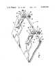
- FIG. 1is a perspective view of two coaxial transmission line to waveguide couplers in accordance with the invention where both coaxial transmission lines are in a common flat plate structure,
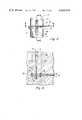
- FIG. 2is an end view of one of the coaxial transmission line to waveguide transitions of FIG. 1,
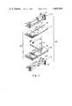
- FIG. 3is an exploded view of one of the transistions of FIG. 1,
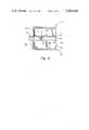
- FIG. 4is a sectional view taken along the line 4--4 of FIG. 2,
- FIG. 5is a sectional view taken along the line 5--5 of FIG. 2.
- a coaxial transmission line to waveguide transition portion of a flat plate coaxial transmission line structureis illustrated generally at 10 in FIG. 1.
- the flat plate structure 20has an upper surface 22, a lower surface 24 and an edge surface 28 and is composed of a main conductive metal plate 30 and a conductive metal cover plate 32.
- a number of coaxial transmission linesare provided within the flat plate structure 20 . Two of these, 40 and 60, are illustrated but in phantom because the cover plate 32 hides then from direct view.
- This flat plate structuremay be a beam former of a phased array antenna and may have as many as eight or more coaxial transmission line to waveguide transistions.
- Two coaxial line to waveguide transitions 100are illustrated. Each is comprised of a portion of the flat plate structure 20 sandwiched between two U-shaped waveguide half pieces 110.
- the waveguide pieces 110are attached to plate structure 20 and each other by bolts through flanges 114.
- the waveguide pieces 110form a longitudinally extending cavity 102.
- Each waveguide piece 110has a terminating wall 112 at one end of cavity 102 and a flange 116 at its other end (118) suitable for attachment to a further waveguide portion of an RF signal transmission system.
- Flanges 116are flush with the edge surface 28 of the flat plate structure.
- the coaxial transmission lines 40 and 60are configured in accordance with the signal transmission desired therein. For example, when they comprise portions of the beam formers in a phased array antenna a succession of power dividers/combiners are used for beam forming.
- FIG. 2is an end-on view of the transition 100 looking directly at the faces 118 of the waveguide flanges 116 and edge surface 28 of the flat plate structure 20.
- the base plate 30 of the flat coaxial structurehas a channel 42 therein which, when the cover plate 32 is attached, defines the inner surface of a coaxial transmission line outer conductor.
- An inner conductor 44is centered within this channel and is held in that position by dielectric spacers 46 which may be made of teflon.
- a tapered slot 50extends completely through the flat plate structure 20 (both base plate 30 and cover plate 32) and along that portion of the flat plate structure 20 which is between the two waveguide pieces 110. The slot 50 is narrowest near the terminating wall 112 and tapers to its broadest at the end 118 of the pieces 110.
- the section view in FIG. 4 taken along line 4--4 of FIG. 2illustrates the alignment between the waveguide pieces 110 and the flat plate structure 20 with greater clarity.
- the outlines of the waveguide cavity 102 and flangesare illustrated by dashed lines 104 and 124, 126 respectively.
- the cavity 102is of constant width.
- the tapered slot 50 in the flat plate structure 20forms vertical side walls 54 which are tapered from a wide spacing (full aperture of waveguide) at waveguide end 118 (open end 52 of slot 50) to a narrow spacing at point 56 where the centerlines of the waveguide and the coaxial line cross and the inner conductor 44 of the coaxial line crosses the slot.
- Slot 50is of constant width from point 56 to the closed end 58 of the slot at wall 112.
- Coaxial transmission line 40extends beyond its intersection 56 with slot 50 and terminates in an open circuit termination 48.
- the waveguideis short circuit terminated by terminating wall 112 approximately a quarter wavelength from intersection 56 for some frequency within the frequency range for which the transistion is designed.
- the open circuit termination 48 of the coaxial transmission line 40is approximately one quarter wavelength from the center line of the waveguide cavity at a frequency within the frequency range for which the transition is designed.
- FIG. 5is a cross-section of FIG. 2 taken along the line 5--5 and includes the waveguide pieces 110, a tuning ridge 106 within each waveguide piece 110 and the flat plate structure 20 including the coaxial transmission line 40.
- the tuning ridges 106aid in providing an extremely low VSWR over a wide frequency range. These ridges are positioned in the waveguide approximately one quarter wavelength from intersection 56 at a frequency within the frequency range for which the transition is designed.
- Terminating wall 112is comprised of wall sections 112a and 112b.
- the entire flat coaxial transmission line structure 20 and waveguide pieces 110are preferably formed by numerically controlled milling of solid aliminum stock.
- the flat plate structure 20is solid aluminum everywhere except for where the coaxial transmission lines are located.
- the use of numerically controlled millingassures the fabrication of a precisely shaped mechanically rugged structure.
- the ridges 106are left by not milling the waveguide pieces as deep at that point as they are along the rest of the waveguide piece. Stubs such as cylindrical rods extending into the waveguide cavity may be sutstituted for the ridges 106 if desired. That procedure is not preferred because of the need to separately form and insert those stubs.
- cover plates 32could be used for each coaxial transmission line if a thicker base plate 30 were utilized and an appropriately sized depression were milled to accommodate the insertion of a more limited cover plate. This could be advantageous in systems where it may be necessary to obtain access to a particular transmission line for adjustment or repair.
- the waveguide portion of the coax-to-waveguide systemconstitutes a waveguide loaded by a double tapered ridge where the ridges are the portions of the flat plate structure 20 which project into the waveguide cavity 102.
- the use of the long taper illustratedfacilitates exact impedance matching of the coaxial transmission line 40 to the waveguide at the intersection 56 between the coaxial transmission line and the waveguide while simultaneously providing a smooth transition to the impedance of a ridgeless waveguide of the same dimensions at the face 118 of the waveguide.
- the inner surfaces 54 of the slot 50are preferably tapered in a manner to constitute a Tchebycheff transfomer section.
- the cavity 102is 0.400 inch (1.02 cm) wide by 1.158 inches (2.94 cm) high by 5.854 inches (14.9 cm) long.
- the flat plate coaxial structure 20has an overall thickness of 0.525 inch (1.33 cm).
- the structurewhen assembled, the structure constitutes a waveguide 0.400 inch (0.101 cm) wide by 2.841 inches (7.22 cm) high by 5.854 inches (14.9 cm) long, and having a loading ridge 0.525 inch (1.33 cm) thick.
- This loading ridgeis of tapering protrusion into the waveguide from the waveguide walls and constitutes a Tchebycheff transformer.
- the slot separating the facing surfaces of the two loading ridgestapers from a width of 0.395 inch (1.0 cm) wide at end 52 (wide end at the flange) to b 0.0948 inch (0.24 cm) wide at intersection 56 and is of constant width from there to the closed end 58 of the slot.
- the cavity for the coaxial lineis 0.400 inch (0.101 cm) square and the inner conductor is 0.161 inch (0.41 cm) square but reduces to 0.90 inch (0.22 cm) wide by 0.161 inch (0.41 cm) high between point 56 where it crosses slot 50 and the open circuit termination 48 of the coaxial line. Over a frequency range of 3.0 to 3.8 GHz the maximum VSWR of this structure was 1.05. This is excellent electrical performance and augments the excellent mechanical compatibility of the structures which eliminate all need for coxial connectors in the vicinity of the coax to waveguide transition.
- An additional advantage of using the ridged waveguide structure for this transitionis that minor variations between the waveguide pieces and the flat plate structure have a minimum effect on the overall performance of this transition, since the construction avoids any attempt to make the inner surfaces of the waveguide and the inner surface of the slot 50 in the flat plate structure co-planar for any extended length. In the event of such an attempt at co-planarity, slight variations would have adverse effects on the transition's electrical performance because of the resulting non-flat wall of the waveguide. In the present structure, such small variations create no problem because of the significant intentional spacing between the inner edge 54 of the slot 50 and the inner surface (104 in FIG. 4) of the waveguide piece 110.
Landscapes
- Waveguide Aerials (AREA)
Abstract
Description
Claims (8)
Priority Applications (1)
| Application Number | Priority Date | Filing Date | Title |
|---|---|---|---|
| US06/313,453US4409566A (en) | 1981-10-21 | 1981-10-21 | Coaxial line to waveguide coupler |
Applications Claiming Priority (1)
| Application Number | Priority Date | Filing Date | Title |
|---|---|---|---|
| US06/313,453US4409566A (en) | 1981-10-21 | 1981-10-21 | Coaxial line to waveguide coupler |
Publications (1)
| Publication Number | Publication Date |
|---|---|
| US4409566Atrue US4409566A (en) | 1983-10-11 |
Family
ID=23215746
Family Applications (1)
| Application Number | Title | Priority Date | Filing Date |
|---|---|---|---|
| US06/313,453Expired - Fee RelatedUS4409566A (en) | 1981-10-21 | 1981-10-21 | Coaxial line to waveguide coupler |
Country Status (1)
| Country | Link |
|---|---|
| US (1) | US4409566A (en) |
Cited By (12)
| Publication number | Priority date | Publication date | Assignee | Title |
|---|---|---|---|---|
| US4636753A (en)* | 1984-05-15 | 1987-01-13 | Communications Satellite Corporation | General technique for the integration of MIC/MMIC'S with waveguides |
| US4803446A (en)* | 1985-03-28 | 1989-02-07 | New Japan Radio Co., Ltd. | Low noise microwave amplifier |
| US5414394A (en)* | 1992-12-29 | 1995-05-09 | U.S. Philips Corporation | Microwave frequency device comprising at least a transition between a transmission line integrated on a substrate and a waveguide |
| US5459471A (en)* | 1993-12-28 | 1995-10-17 | Hughes Aircraft Company | Flared trough radiator |
| US20040263277A1 (en)* | 2003-06-30 | 2004-12-30 | Xueru Ding | Apparatus for signal transitioning from a device to a waveguide |
| US20060246843A1 (en)* | 2002-12-20 | 2006-11-02 | Taavi Hirvonen | Method and arrangement for testing a radio device |
| US20100328188A1 (en)* | 2009-06-26 | 2010-12-30 | Raytheon Company | Compact loaded-waveguide element for dual-band phased arrays |
| US20140205231A1 (en)* | 2012-07-06 | 2014-07-24 | Teledyne Scientific & Imaging Llc | Method of fabricating silicon waveguides with embedded active circuitry |
| CN105612654A (en)* | 2013-10-07 | 2016-05-25 | 日本电气株式会社 | Waveguide coaxial conversion equipment and transmitting/receiving integrated wave splitter |
| CN105612655A (en)* | 2013-10-07 | 2016-05-25 | 日本电气株式会社 | Coaxial wiring device and transmitter-receiver demultiplexer |
| US11047951B2 (en) | 2015-12-17 | 2021-06-29 | Waymo Llc | Surface mount assembled waveguide transition |
| US11804681B1 (en)* | 2019-05-30 | 2023-10-31 | SAGE Millimeter, Inc. | Waveguide to coaxial conductor pin connector |
Citations (5)
| Publication number | Priority date | Publication date | Assignee | Title |
|---|---|---|---|---|
| US2924797A (en)* | 1955-11-29 | 1960-02-09 | Bell Telephone Labor Inc | Finline coupler |
| US3725824A (en)* | 1972-06-20 | 1973-04-03 | Us Navy | Compact waveguide-coax transition |
| US4144506A (en)* | 1977-09-23 | 1979-03-13 | Litton Systems, Inc. | Coaxial line to double ridge waveguide transition |
| US4157516A (en)* | 1976-09-07 | 1979-06-05 | U.S. Philips Corporation | Wave guide to microstrip transition |
| US4260964A (en)* | 1979-05-07 | 1981-04-07 | The United States Of America As Represented By The Secretary Of The Navy | Printed circuit waveguide to microstrip transition |
- 1981
- 1981-10-21USUS06/313,453patent/US4409566A/ennot_activeExpired - Fee Related
Patent Citations (5)
| Publication number | Priority date | Publication date | Assignee | Title |
|---|---|---|---|---|
| US2924797A (en)* | 1955-11-29 | 1960-02-09 | Bell Telephone Labor Inc | Finline coupler |
| US3725824A (en)* | 1972-06-20 | 1973-04-03 | Us Navy | Compact waveguide-coax transition |
| US4157516A (en)* | 1976-09-07 | 1979-06-05 | U.S. Philips Corporation | Wave guide to microstrip transition |
| US4144506A (en)* | 1977-09-23 | 1979-03-13 | Litton Systems, Inc. | Coaxial line to double ridge waveguide transition |
| US4260964A (en)* | 1979-05-07 | 1981-04-07 | The United States Of America As Represented By The Secretary Of The Navy | Printed circuit waveguide to microstrip transition |
Cited By (20)
| Publication number | Priority date | Publication date | Assignee | Title |
|---|---|---|---|---|
| US4636753A (en)* | 1984-05-15 | 1987-01-13 | Communications Satellite Corporation | General technique for the integration of MIC/MMIC'S with waveguides |
| US4803446A (en)* | 1985-03-28 | 1989-02-07 | New Japan Radio Co., Ltd. | Low noise microwave amplifier |
| US5414394A (en)* | 1992-12-29 | 1995-05-09 | U.S. Philips Corporation | Microwave frequency device comprising at least a transition between a transmission line integrated on a substrate and a waveguide |
| US5459471A (en)* | 1993-12-28 | 1995-10-17 | Hughes Aircraft Company | Flared trough radiator |
| US20060246843A1 (en)* | 2002-12-20 | 2006-11-02 | Taavi Hirvonen | Method and arrangement for testing a radio device |
| US7680463B2 (en)* | 2002-12-20 | 2010-03-16 | Jot Automation Oy | Method and arrangement for testing a radio device |
| US20040263277A1 (en)* | 2003-06-30 | 2004-12-30 | Xueru Ding | Apparatus for signal transitioning from a device to a waveguide |
| EP1494309A1 (en)* | 2003-06-30 | 2005-01-05 | M/A-Com, Inc. | Apparatus for signal transitioning from a device to a waveguide |
| US7068121B2 (en) | 2003-06-30 | 2006-06-27 | Tyco Technology Resources | Apparatus for signal transitioning from a device to a waveguide |
| US8217852B2 (en) | 2009-06-26 | 2012-07-10 | Raytheon Company | Compact loaded-waveguide element for dual-band phased arrays |
| US20100328188A1 (en)* | 2009-06-26 | 2010-12-30 | Raytheon Company | Compact loaded-waveguide element for dual-band phased arrays |
| US20140205231A1 (en)* | 2012-07-06 | 2014-07-24 | Teledyne Scientific & Imaging Llc | Method of fabricating silicon waveguides with embedded active circuitry |
| US8995800B2 (en)* | 2012-07-06 | 2015-03-31 | Teledyne Scientific & Imaging, Llc | Method of fabricating silicon waveguides with embedded active circuitry |
| US20150185416A1 (en)* | 2012-07-06 | 2015-07-02 | Teledyne Scientific & Imaging, Llc | Silicon waveguides with embedded active circuitry |
| CN105612654A (en)* | 2013-10-07 | 2016-05-25 | 日本电气株式会社 | Waveguide coaxial conversion equipment and transmitting/receiving integrated wave splitter |
| CN105612655A (en)* | 2013-10-07 | 2016-05-25 | 日本电气株式会社 | Coaxial wiring device and transmitter-receiver demultiplexer |
| EP3057174A4 (en)* | 2013-10-07 | 2017-05-17 | NEC Corporation | Coaxial waveguide converter and transmitting/receiving integrated splitter |
| US9831539B2 (en) | 2013-10-07 | 2017-11-28 | Nec Corporation | Waveguide coaxial conversion device and transmission/reception integrated splitter |
| US11047951B2 (en) | 2015-12-17 | 2021-06-29 | Waymo Llc | Surface mount assembled waveguide transition |
| US11804681B1 (en)* | 2019-05-30 | 2023-10-31 | SAGE Millimeter, Inc. | Waveguide to coaxial conductor pin connector |
Similar Documents
| Publication | Publication Date | Title |
|---|---|---|
| US4672384A (en) | Circularly polarized radio frequency antenna | |
| US4651115A (en) | Waveguide-to-microstrip transition | |
| US4370659A (en) | Antenna | |
| US5309165A (en) | Positioner with corner contacts for cross notch array and improved radiator elements | |
| US4409566A (en) | Coaxial line to waveguide coupler | |
| US5359339A (en) | Broadband short-horn antenna | |
| JPS58168304A (en) | Antenna element | |
| US5600286A (en) | End-on transmission line-to-waveguide transition | |
| US6407722B1 (en) | Choke coupled coaxial connector | |
| IL132960A (en) | Microwave transmission device | |
| US20060038732A1 (en) | Broadband dual polarized slotline feed circuit | |
| DE112016006983B4 (en) | coaxial waveguide-hollow waveguide transition circuit | |
| US4539534A (en) | Square conductor coaxial coupler | |
| US4353072A (en) | Circularly polarized radio frequency antenna | |
| CA1260083A (en) | Phase slope equalizer for satellite attennas | |
| US4867704A (en) | Fixture for coupling coaxial connectors to stripline circuits | |
| US4783639A (en) | Wideband microwave diplexer including band pass and band stop resonators | |
| US4673946A (en) | Ridged waveguide to rectangular waveguide adaptor useful for feeding phased array antenna | |
| US4983933A (en) | Waveguide-to-stripline directional coupler | |
| US3332039A (en) | Three conductor coplanar serpentineline directional coupler | |
| US7002433B2 (en) | Microwave coupler | |
| US4353074A (en) | Radio frequency ridged waveguide antenna | |
| CN216288894U (en) | Waveguide plane transmission line transition structure with wide frequency band and low insertion loss | |
| US4071833A (en) | Apparatus for coupling coaxial transmission line to rectangular waveguide | |
| US4558290A (en) | Compact broadband rectangular to coaxial waveguide junction |
Legal Events
| Date | Code | Title | Description |
|---|---|---|---|
| AS | Assignment | Owner name:RCA CORPORATION A CORP OF DE Free format text:ASSIGNMENT OF ASSIGNORS INTEREST.;ASSIGNORS:PATTON, WILLARD T.;MASON, ROBERT J.;REEL/FRAME:003941/0229 Effective date:19811015 Owner name:RCA CORPORATION A CORP OF, DELAWARE Free format text:ASSIGNMENT OF ASSIGNORS INTEREST;ASSIGNORS:PATTON, WILLARD T.;MASON, ROBERT J.;REEL/FRAME:003941/0229 Effective date:19811015 | |
| MAFP | Maintenance fee payment | Free format text:PAYMENT OF MAINTENANCE FEE, 4TH YEAR, PL 96-517 (ORIGINAL EVENT CODE: M170); ENTITY STATUS OF PATENT OWNER: LARGE ENTITY Year of fee payment:4 | |
| FEPP | Fee payment procedure | Free format text:MAINTENANCE FEE REMINDER MAILED (ORIGINAL EVENT CODE: REM.); ENTITY STATUS OF PATENT OWNER: LARGE ENTITY | |
| LAPS | Lapse for failure to pay maintenance fees | ||
| FP | Lapsed due to failure to pay maintenance fee | Effective date:19911013 | |
| STCH | Information on status: patent discontinuation | Free format text:PATENT EXPIRED DUE TO NONPAYMENT OF MAINTENANCE FEES UNDER 37 CFR 1.362 |