US4408842A - Telescopic sight having lens holder tube with half socket pivot mount - Google Patents
Telescopic sight having lens holder tube with half socket pivot mountDownload PDFInfo
- Publication number
- US4408842A US4408842AUS06/309,826US30982681AUS4408842AUS 4408842 AUS4408842 AUS 4408842AUS 30982681 AUS30982681 AUS 30982681AUS 4408842 AUS4408842 AUS 4408842A
- Authority
- US
- United States
- Prior art keywords
- tube
- reticle
- lens
- accordance
- pivot
- Prior art date
- Legal status (The legal status is an assumption and is not a legal conclusion. Google has not performed a legal analysis and makes no representation as to the accuracy of the status listed.)
- Expired - Lifetime
Links
Images

Classifications
- G—PHYSICS
- G02—OPTICS
- G02B—OPTICAL ELEMENTS, SYSTEMS OR APPARATUS
- G02B23/00—Telescopes, e.g. binoculars; Periscopes; Instruments for viewing the inside of hollow bodies; Viewfinders; Optical aiming or sighting devices
- G02B23/14—Viewfinders
- G02B23/145—Zoom viewfinders
- G—PHYSICS
- G02—OPTICS
- G02B—OPTICAL ELEMENTS, SYSTEMS OR APPARATUS
- G02B27/00—Optical systems or apparatus not provided for by any of the groups G02B1/00 - G02B26/00, G02B30/00
- G02B27/32—Fiducial marks and measuring scales within the optical system
Definitions
- the subject matter of the present inventionrelates generally to telescopic sights for optical instruments, and in particular, to a telescopic sight apparatus having a lens holder tube pivotally mounted on a half socket pivot means for limited universal adjustment of such tube.
- the present telescopic sight apparatuspreferably includes a lens holder tube containing image erector lenses aligned on an optical axis and which is mounted on a half socket pivot means at the rear end of such tube with a spherical pivot surface.
- the spherical pivot surfacehas its center of curvature coincident with the sight point of a reticle on the erector lens system axis when such reticle is mounted outside the lens holder tube, in order to maintain such reticle sight point centered on such axis in different pivot positions of the lens holder tube.
- Such telescopic sight apparatusis especially useful as a rifle scope, but can also be employed in other optical instruments such as a surveying instrument.
- such rifle scopemounts the reticle within the lens holder tube and with its sight point in alignment with the erector lens axis so that such reticle moves with the tube during pivoting adjustments of such tube to compensate for changes in windage and target range elevation.
- an elastic couplingsuch as a rubber ring member, which is bonded between the end of the lens holder tube and the surrounding housing to provide limited universal movement of the lens holder tube about a pivot center which changes in position because of the nature of such elastic coupling.
- Such elastic coupling pivot meansis, also, discussed in U.S. Pat. No. 2,948,188 of Kollmorgan, issued Aug. 9, 1960 and U.S. Pat. No.
- the elastic coupling pivot meanshas the additional disadvantage that it enables relative movement of the erector lens tube holder with respect to the scope housing during rifle recoil which can damage the reticle and the erector lenses including their mounts.
- such half socket pivot meansdo not position such pivot surface so that its center of curvature is coincident with the sight point of the reticle to maintain such reticle centered on the erector lens axis in the manner of the present invention.
- the reticleis fixed inside the front end of the lens holder tube, apparently in alignment with the objective lens focal plane, which has the disadvantage that any magnification of the objective image by the erector lenses also magnifies the reticle image so it obscures a larger portion of the transmitted target image.
- the reticleis not resiliently mounted by means of a calibration spring to enable the reticle to be located at a calibration position which is in focus in both the maximum and minimum magnification positions of the erector lenses in a variable power scope of the Burris et al U.S. Pat. No. 3,161,716 or any of the other above-discussed patents. Therefore, the telescopic sight apparatus of the present invention further distinguishes from such patents in employing such calibration spring reticle mounting.
- Such calibration springalso, absorbes rifle recoil to maintain the reticle in the calibrated position, and to prevent damage to the reticle.
- the half socket pivot means of the present inventionhas the further advantages of reduced wear, longer lifetime and being self-centering due to the conical shape of the socket into which the spherical shaped pivot surface is urged by the socket spring. Also, by providing a substantially point contact between the conical socket surface and the spherical pivot surface, the center of the present pivot means is fixed on the erector lens axis at a point coincident with the sight point of the reticle to maintain the reticle centered.
- Another object of the inventionis to provide such an improved telescopic sight apparatus with a half socket pivot means including a spherical pivot surface held in contact with a socket surface by a socket spring for easy assembly and to permit limited universal pivoting adjustment of the lens holder tube containing the erector lens system.
- An additional object of the inventionis to provide such an improved telescopic sight apparatus in which the reticle is mounted outside the lens holder tube so that the sight point of such reticle coincides with the center of the radius of curvature of the spherical pivot surface of such socket means to maintain the reticle image centered on the axis of the erector lens system in different adjustment positions of the lens holder tube.
- Still another object of the inventionis to provide an improved telescopic sight apparatus in which the half socket pivot means is formed with a conical socket surface which is engaged by the spherical pivot surface to provide a self-centering pivot means and a more accurate pivot point.
- a still further object of the inventionis to provide an improved rifle scope with a half socket pivot means which enables limited universal pivoting adjustment of the lens holder tube for a long, useful life without binding, and which is easy to assemble.
- a still additional object of the inventionis to provide such an improved rifle scope of variable magnification in which the reticle is mounted by means of a calibration adjustment spring at a calibrated position where such reticle is in focus for all magnification settings of the scope.
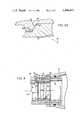
- FIG. 1is a section view of a variable magnification rifle scope made in accordance with the present invention
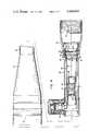
- FIG. 2is an enlarged view of a portion of FIG. 1 showing the half socket pivot means and reticle mounting means of the present invention
- FIG. 2Ais a further enlarged view of a portion of FIG. 2;
- FIG. 3is an enlarged section view of a second embodiment of the half socket pivot means and reticle mounting means which may be employed in the variable magnification scope of FIG. 1;
- FIG. 4is an enlarged view of a third embodiment of the half socket pivot means and reticle mounting means employed in a fixed magnification scope.
- a variable magnification telescopic sight apparatus for a firearmsuch as a rifle scope, made in accordance with the present invention includes an objective lens system 10 and an ocular or eyepiece lens system 12 which are supported within an objective housing shell 14 and an eyepiece housing shell 16, respectively.
- An image erector lens systemincluding a first erector lens 18 and a second erector lens 20 are supported between the objective lens and eyepiece lens within a lens holder tube 22 with the centers of such erector lenses aligned along an optical axis 24 extending axially through such tube.
- the lens holder tube 22is pivotally mounted by a half socket pivot means 26 at the rear end of such tube within a rear housing tube 28.
- the rear end of the rear housing tube 28is threadedly connected to the eyepiece housing shell 16 while the front end of such housing tube is threadedly connected to the right side of a turret housing 30.
- the turret housing 30contains two adjustment screws 32 extending at right angles to each other into engagement with the front end of the lens housing tube 22 in order to pivotally adjust such tube vertically and horizontally in two mutually perpendicular directions to compensate for changes in windage and in target range elevation.
- a leaf springbiases the lens housing tube 22 into contact with the windage and elevation adjustment screws 32 so that the setting of such screws causes a limited universal pivoting movement of such tube about the half socket pivot means 26 to locate the tube and the erector lenses 18 and 20 mounted therein in the desired sighting position for the particular windage and range elevation of the target being viewed by such scope.
- the objective housing shell 14is threadedly connected to the front end of a front housing tube 34 whose rear end is threadedly connected into the left side of the turret housing 30.
- a field lens 36may be supported rearward of the objective lens focal plane 37 and in front of the first erector lens 18 by mounting such field lens within the lens holder tube 22 and clamping it in place by a tube extension 38 which is threaded into the front end of such lens holder tube.
- the field lensis mounted in a fixed position within the lens holder tube, and centered on the optical axis 24 of such tube.
- the first and second erector lenses 18 and 20are mounted on movable lens holders 40 and 42, respectively, which can be adjusted longitudinally within the holder tube 22 by rotation of a cam tube 44 that surrounds the holder tube.
- the cam tube 44is coupled to the lens holders 40 and 42 by means of cam followers 46 and 48, respectively, attached thereto by screws, such cam followers sliding within arcuate cam slots provided in the cam tube 44 during rotation of such cam tube.
- the cam followersalso extend through a linear guide slot in the side of the lens holder tube 22 which prevents rotation of the lens holders 40 and 42 during their longitudinal movement of lenses 18 and 20 along the optical axis 22 to change the magnification of the scope.
- a power selector ring 50is mounted on the exterior of the rear housing tube 28 and is coupled by a drive pin 52 through such housing tube to the cam tube 44 for rotation of such cam tube in response to rotation of such selector ring between maximum and minimum powers of magnification.
- the rifle scope of FIGS. 1 and 2is similar to that shown in U.S. Pat. No. 3,161,716 of Burris et al discussed above.
- the half socket pivot means 26includes a spherical pivot surface 54 provided on an external shoulder at the rear end of the lens holder tube 22, and a conical socket surface 56 formed on the rear surface of an internal shoulder 58 on the rear housing tube 28.
- the conical socket surfaceextends at an angle of about 45 degrees with the optical axis 24.
- a socket spring 60 of the wave spring typeresiliently urges the spherical pivot surface 54 into engagement with the conical socket surface 56 to hold the assembled half socket pivot means 26 together, and to enable easy pivoting adjustment of such pivot means for limited universal movement about the fixed pivot point 62 on the erector lens axis 24 which corresponds to the center of the radius of curvature of the spherical pivot surface 54.
- the radius of curvature 63 of the spherical pivot surface 54may be about 0.717 inch.
- the line of contact between the spherical pivot surface 54 and the conical socket surface 56is an annular line of tangency extending around the conical surface concentric with the axis 24 which reduces friction and enables easier pivoting.
- the conical socket surfaceprovides self-centering of the spherical pivot surface 52 to maintain the pivot point 62 centered on the axis 24 when such pivot surface is urged into contact with such socket surface by the socket spring 60. Also, the socket spring compensates for manufacturing tolerances of parts forming the pivot means 26 and allows such pivot means to be quickly assembled without any adjustment.
- a reticle or sight 64which may be formed by two intersecting wires whose intersections provides a sight point, is supported on a reticle mounting ring 66 within the rear housing tube 28.
- the reticleis supported in the scope of FIGS. 1 and 2 outside of the lens holder tube 22 at a position rearward of the pivot means 26 where such sight point is coincident with the pivot point 62 corresponding to the center of the radius of curvature of the spherical pivot surface 54.
- the reticle 64remains centered in the field of view of the erector lenses 18 and 20 and the sight point 62 is maintained in alignment with the optical axis 24 in all pivot positions of the lens holder tube 22.
- the reticle mounting ring 66is held in compression between a locking ring 68 which is threaded inside the right end of the rear housing tube 28 into engagement with the right side of the reticle mounting ring.
- a thrust washer 70is resiliently urged into engagement with the left side of the reticle mounting ring by a calibration adjustment spring 72 of the wave spring type which is provided between the thrust washer 70 and a step washer 74.
- the step washerhas an external shoulder which engages shoulder 76 on the inner surface of the rear housing tube 28 to the right of the pivot socket shoulder 58. Such step washer also engages the socket spring 60 to compress such socket spring between the step washer and the rear end of the lens holder tube 22.
- the centering sleeveis formed of a tapered cross-section so that it is wedged between the outer surface of the reticle mounting ring 66 and the inner surface of the rear housing tube 28 when the lock ring 68 is tightened.
- the centering sleeve 78centers the reticle mounting ring 66 within the housing sleeve 28 so that the sight point of the reticle is in alignment with the optical axis 24, and preferably, coincides with the pivot point 62 at the center of the radius of curvature of the spherical pivot surface 54 of the half socket pivot means 26.
- the reticle 64While ordinarily the reticle 64 is mounted in the focal plane 80 of the eyepiece lens system 12, it may be necessary to displace the reticle from such focal plane slightly because during manufacture the reticle is adjusted to a calibration position where it is in focus during the entire range of magnification adjustments of the erector lenses 18 and 20 between the minimum and maximum magnification powers of the scope of the power selector ring 50. Longitudinal calibration adjustment of the reticle 64 is achieved by screw adjustment of the locking ring 68 to compress the calibration adjustment spring 72. It should be noted that the calibration adjustment spring 72 is a much heavier weight spring than the socket spring 60 because such calibration spring 72 must enable calibration adjustments of the reticle mounting ring 66, and provide shock absorption against rifle recoil for such reticle mounting ring. In addition, the lock ring 68 provides a diaphragm opening 81 which serves as a field stop to limit the viewing field of the eyepiece lens system 12.
- FIG. 3Another embodiment of the variable magnification rifle scope is shown in FIG. 3 to be similar to that of FIGS. 1 and 2 except that the reticle 64 is mounted within the rear end of the lens holder tube 22, not outside of such tube.
- the same reference numeralshave been used on like parts in FIG. 3 so that only the differences between such embodiment and that of FIGS. 1 and 2 will be described.
- the half socket pivot means 26is still formed by a spherical pivot surface 54 on the rear end of the lens tube 22 and a conical socket surface 56 on an internal shoulder 58 of the rear housing tube 28.
- the socket spring 60is urged against the rear end of the lens holder tube 22 by another lock ring 82 which is threaded into the right end of the rear housing tube 28 until a stop flange on the end of such lock ring engages the end of such housing tube.
- the step washer 74 of FIG. 2is eliminated, as is the internal shoulder 76 against which the step washer rests.
- the reticle mounting ring 66is compressed against an internal shoulder stop 84 formed on the inner surface of the right end of the lens tube 22.
- the right side of the reticle mounting ring 66is resiliently engaged by the thrust washer 70 and the calibration adjustment spring 72 is positioned between such washer and a locking ring 68' threaded into the right end of the lens holder tube 22 which clamps the assembly in the manner similar to locking ring 68 of FIG. 2.
- a centering sleeve 78is provided in FIG. 3 about the right end of the reticle mounting ring 66 for centering such mounting ring in a similar manner to FIG. 2. It should be noted that the reticle 64 is not supported so that its sight point is coincident with the pivot point 62 at the center of the radius of curvature of the spherical pivot surface 54. This is not necessary in the embodiment of FIG. 3 because the reticle 64 is mounted within the lens holder tube 22 and moves with such lens tube as it is pivoted about the half socket pivot means 26. As a result, the sight point of the reticle 64 remains centered on the optical axis 24 of the erector lenses in all pivot positions of the lens holder tube.
- FIG. 4A third embodiment of the rifle scope of the present invention is shown in FIG. 4 with the same reference numbers designating like parts.
- This scopeis of a fixed magnification so that the erector lenses 18 and 20 do not move longitudinally within the lens holder tube 22 for changing the magnification power of such scope. Instead, the erector lenses are held fixed in the position into which they are set by a lock nut ring 86 which clamps such lenses in a lens holder 88 threadedly supported within the front end of lens holder tube 22.
- the first erector lens 18'is spaced from the second erector lens 20 by a spacer sleeve 90 to maintain the distance between such lenses constant.
- the embodiment of FIG. 4also includes a half socket pivot means 26 including a spherical pivot surface 54 provided on the exterior of the rear end of the lens tube holder 22 and a conical socket surface 56 provided on an internal shoulder 58 of the rear housing tube 28 which are held together by the socket spring 60.
- the reticle 64is positioned so that its sight point corresponds to the pivot point 62 where the center of the radius of curvature of the spherical pivot surface 54 intersects the erector lens axis 24.
Landscapes
- Physics & Mathematics (AREA)
- General Physics & Mathematics (AREA)
- Optics & Photonics (AREA)
- Astronomy & Astrophysics (AREA)
- Telescopes (AREA)
- Aiming, Guidance, Guns With A Light Source, Armor, Camouflage, And Targets (AREA)
Abstract
Description
Claims (20)
Priority Applications (1)
| Application Number | Priority Date | Filing Date | Title |
|---|---|---|---|
| US06/309,826US4408842A (en) | 1981-10-08 | 1981-10-08 | Telescopic sight having lens holder tube with half socket pivot mount |
Applications Claiming Priority (1)
| Application Number | Priority Date | Filing Date | Title |
|---|---|---|---|
| US06/309,826US4408842A (en) | 1981-10-08 | 1981-10-08 | Telescopic sight having lens holder tube with half socket pivot mount |
Publications (1)
| Publication Number | Publication Date |
|---|---|
| US4408842Atrue US4408842A (en) | 1983-10-11 |
Family
ID=23199826
Family Applications (1)
| Application Number | Title | Priority Date | Filing Date |
|---|---|---|---|
| US06/309,826Expired - LifetimeUS4408842A (en) | 1981-10-08 | 1981-10-08 | Telescopic sight having lens holder tube with half socket pivot mount |
Country Status (1)
| Country | Link |
|---|---|
| US (1) | US4408842A (en) |
Cited By (54)
| Publication number | Priority date | Publication date | Assignee | Title |
|---|---|---|---|---|
| US4643542A (en)* | 1984-02-27 | 1987-02-17 | Leupold & Stevens | Telescopic sight with erector lens focus adjustment |
| US4669833A (en)* | 1985-01-25 | 1987-06-02 | Simmons Outdoor Corporation | Spotting scope with alignment viewer |
| US5299067A (en)* | 1992-12-15 | 1994-03-29 | Markzmen Optics | Auxiliary lens attachment |
| US5671088A (en)* | 1992-06-03 | 1997-09-23 | Leupold & Stevens, Inc. | Variable optical aiming devices |
| US5920995A (en)* | 1997-12-08 | 1999-07-13 | Sammut; Dennis J. | Gunsight and reticle therefor |
| USD417679S (en)* | 1998-10-28 | 1999-12-14 | Bushnell Corporation | Rifle scope with zoom |
| US6005711A (en)* | 1998-01-21 | 1999-12-21 | Leupold & Stevens, Inc. | Variable optical power telescopic sight with side focus control |
| EP0654650B2 (en)† | 1993-11-18 | 2001-02-07 | Swarovski Optik Kg | Device for adjusting the reticle of an aiming telescope |
| US6453595B1 (en) | 1997-12-08 | 2002-09-24 | Horus Vision, Llc | Gunsight and reticle therefor |
| US6469829B2 (en)* | 2001-01-09 | 2002-10-22 | Leupold & Stevens, Inc. | Equalized pivot mount for riflescope |
| DE10116997A1 (en)* | 2001-04-05 | 2002-10-31 | Hensoldt & Soehne Optik | Scope |
| US6516699B2 (en) | 1997-12-08 | 2003-02-11 | Horus Vision, Llc | Apparatus and method for calculating aiming point information for rifle scopes |
| US6519890B1 (en) | 2000-07-28 | 2003-02-18 | Leupold & Stevens, Inc. | Radial detents for rifle scope adjustment |
| US6591537B2 (en)* | 1998-09-14 | 2003-07-15 | Thomas D. Smith | Reticle for telescopic gunsight and method for using |
| US6604316B1 (en) | 2002-09-16 | 2003-08-12 | Bryan A. Custer | Offset attachment for use with a firearm scope |
| US6643970B2 (en)* | 2002-01-31 | 2003-11-11 | Jeffrey Huber | Zero stop adjustable rifle scope |
| US20040080819A1 (en)* | 2002-10-28 | 2004-04-29 | Leupold & Stevens, Inc. | Pre-assembled pivoting lens unit |
| US20050021282A1 (en)* | 1997-12-08 | 2005-01-27 | Sammut Dennis J. | Apparatus and method for calculating aiming point information |
| US20060168871A1 (en)* | 2001-04-05 | 2006-08-03 | Thomas Wagner | Sighting telescope |
| US20070044364A1 (en)* | 1997-12-08 | 2007-03-01 | Horus Vision | Apparatus and method for calculating aiming point information |
| US20070062091A1 (en)* | 2004-11-22 | 2007-03-22 | Thomas Mark A | Optical sight with side focus adjustment |
| US20080236018A1 (en)* | 2006-10-20 | 2008-10-02 | Leupold & Stevens, Inc. | Pop-up adjustment cap system for sighting device |
| US20090205461A1 (en)* | 2004-11-30 | 2009-08-20 | Leupold & Stevens, Inc. | Locking Turret Knob |
| US20090235570A1 (en)* | 1997-12-08 | 2009-09-24 | Horus Vision | Apparatus and method for calculating aiming point information |
| US20100238542A1 (en)* | 2005-07-20 | 2010-09-23 | Swarovski-Optik Kg. | Far-optical device |
| US7827723B1 (en) | 2006-10-20 | 2010-11-09 | Leupold & Stevens, Inc. | Lateral de-centering of riflescope objective for aiming adjustment |
| US20110100152A1 (en)* | 2009-11-04 | 2011-05-05 | Leupold & Stevens, Inc. | Auto-locking adjustment device |
| US7944611B1 (en) | 2008-03-29 | 2011-05-17 | Leupold & Stevens, Inc. | High zoom ratio optical sighting device |
| US20110132983A1 (en)* | 2009-05-15 | 2011-06-09 | Horus Vision Llc | Apparatus and method for calculating aiming point information |
| US8172139B1 (en) | 2010-11-22 | 2012-05-08 | Bitterroot Advance Ballistics Research, LLC | Ballistic ranging methods and systems for inclined shooting |
| US8270104B2 (en) | 2008-06-22 | 2012-09-18 | Windauer Bernard T | Operator-selectable-stop turret knob |
| USD675239S1 (en)* | 2011-11-01 | 2013-01-29 | Leupold & Stevens, Inc. | Spotting scope |
| US8670179B2 (en) | 2008-12-08 | 2014-03-11 | Bernard T. Windauer | Multi-function turret knob |
| US8701330B2 (en) | 2011-01-01 | 2014-04-22 | G. David Tubb | Ballistic effect compensating reticle and aim compensation method |
| DE212013000042U1 (en) | 2012-01-04 | 2014-08-06 | Leupold & Stevens, Inc. | Arretiereinstellvorrichtung |
| US8893423B2 (en) | 2011-05-27 | 2014-11-25 | G. David Tubb | Dynamic targeting system with projectile-specific aiming indicia in a reticle and method for estimating ballistic effects of changing environment and ammunition |
| US8959824B2 (en) | 2012-01-10 | 2015-02-24 | Horus Vision, Llc | Apparatus and method for calculating aiming point information |
| US9121672B2 (en) | 2011-01-01 | 2015-09-01 | G. David Tubb | Ballistic effect compensating reticle and aim compensation method with sloped mil and MOA wind dot lines |
| EP2924386A1 (en)* | 2014-03-28 | 2015-09-30 | Trijicon, Inc. | Optical sight with relay assembly |
| US9182773B2 (en) | 2013-01-14 | 2015-11-10 | Leupold & Stevens, Inc. | Low profile auto-locking pinch/turn adjustment knob |
| RU2568955C1 (en)* | 2014-06-23 | 2015-11-20 | Акционерное общество "Швабе-Оборона и Защита" (АО "Швабе-Оборона и Защита") | Optic sight |
| US20160040959A1 (en)* | 2014-08-08 | 2016-02-11 | Gunwerks, Llc | Rifle scope elevation turret mechanism |
| USRE46011E1 (en) | 2008-01-31 | 2016-05-24 | Lightforce Usa, Inc. | Locking adjustment dial mechanism for riflescope |
| US20180024376A1 (en)* | 2016-07-22 | 2018-01-25 | Swarovski-Optik Kg. | Long-range optical device with a graticule |
| US10254082B2 (en) | 2013-01-11 | 2019-04-09 | Hvrt Corp. | Apparatus and method for calculating aiming point information |
| WO2020161781A1 (en)* | 2019-02-05 | 2020-08-13 | 株式会社ライト光機製作所 | Optical sight |
| US10823532B2 (en) | 2018-09-04 | 2020-11-03 | Hvrt Corp. | Reticles, methods of use and manufacture |
| US20210190457A1 (en)* | 2010-09-29 | 2021-06-24 | In Jung | Optical scope |
| US11320239B2 (en) | 2019-11-19 | 2022-05-03 | Raytheon Canada Ltd.—Elcan | Compact prismatic optical sight with internal zeroing method |
| US11480411B2 (en) | 2011-01-01 | 2022-10-25 | G. David Tubb | Range-finding and compensating scope with ballistic effect compensating reticle, aim compensation method and adaptive method for compensating for variations in ammunition or variations in atmospheric conditions |
| WO2024186547A1 (en) | 2023-03-06 | 2024-09-12 | Leupold & Stevens, Inc. | Toolless knob assembly for optical device |
| WO2024196671A1 (en) | 2023-03-23 | 2024-09-26 | Leupold & Stevens, Inc. | Rotatable drive device for scope turret or other optic turret |
| WO2024226676A1 (en) | 2023-04-28 | 2024-10-31 | Leupold & Stevens, Inc. | Locking adjustment device |
| WO2025183744A2 (en) | 2023-09-27 | 2025-09-04 | Leupold & Stevens, Inc. | Riflescope or other optical device with pivotable system erector |
Citations (18)
| Publication number | Priority date | Publication date | Assignee | Title |
|---|---|---|---|---|
| DE1013090B (en) | 1954-12-20 | 1957-08-01 | Hertel & Reuss Optik Und Feinm | Rifle scope with variable magnification |
| US2858732A (en)* | 1955-08-25 | 1958-11-04 | Kollmorgen Optical Corp | Mechanism for eliminating parallax from telescopic sights and the like |
| US2948188A (en)* | 1958-08-25 | 1960-08-09 | Redfield Gun Sight Co | Telescope sight |
| US2949816A (en)* | 1956-01-16 | 1960-08-23 | William R Weaver | Telescope sight for firearms |
| US2955512A (en)* | 1956-04-03 | 1960-10-11 | Redfield Gun Sight Co | Telescope rifle sight with pivoted reticle and erector lens tube |
| US2997916A (en)* | 1959-02-20 | 1961-08-29 | Redfield Gun Sight Co | Telescopic gun sight having axially adjustable eyepiece and parallax tube |
| US3184852A (en)* | 1961-09-20 | 1965-05-25 | Lyman Gun Sight Corp | Telescopic sight |
| US3213539A (en)* | 1963-03-04 | 1965-10-26 | Redfield Gun Sight Company | Adjustable reticle assembly for optical sighting devices |
| US3297389A (en)* | 1963-01-11 | 1967-01-10 | Leupold & Stevens Instr Inc | Rifle scope with ball joint mounting for adjustable erector lens tube |
| US3336831A (en)* | 1963-08-08 | 1967-08-22 | Jr John Unertl | Cam focusing system for optical instruments |
| FR1503152A (en) | 1966-12-02 | 1967-11-24 | Scope for firearm | |
| US3464758A (en)* | 1964-11-18 | 1969-09-02 | Realist | Riflescope with o-ring support and multiple lead fine threaded eyepiece |
| US3506330A (en)* | 1967-07-18 | 1970-04-14 | Ralph G Allen | Telescopic rangefinding gunsight automatic elevation adjustment |
| US3684376A (en)* | 1970-09-10 | 1972-08-15 | Donald E Lessard | Ranger-finder in a telescopic sight |
| US3902251A (en)* | 1974-07-17 | 1975-09-02 | Weaver Co W R | Adjustable reticle for telescopic rifle sights |
| US3918791A (en)* | 1974-10-18 | 1975-11-11 | Leupold & Stevens Inc | Flat field variable power rifle scope |
| US4200355A (en)* | 1978-08-08 | 1980-04-29 | Fontaine Industries, Inc. | Telescopic scope having an integrally formed saddle |
| US4255013A (en)* | 1979-05-17 | 1981-03-10 | John E. McNair | Rifle scope having compensation for elevation and drift |
- 1981
- 1981-10-08USUS06/309,826patent/US4408842A/ennot_activeExpired - Lifetime
Patent Citations (18)
| Publication number | Priority date | Publication date | Assignee | Title |
|---|---|---|---|---|
| DE1013090B (en) | 1954-12-20 | 1957-08-01 | Hertel & Reuss Optik Und Feinm | Rifle scope with variable magnification |
| US2858732A (en)* | 1955-08-25 | 1958-11-04 | Kollmorgen Optical Corp | Mechanism for eliminating parallax from telescopic sights and the like |
| US2949816A (en)* | 1956-01-16 | 1960-08-23 | William R Weaver | Telescope sight for firearms |
| US2955512A (en)* | 1956-04-03 | 1960-10-11 | Redfield Gun Sight Co | Telescope rifle sight with pivoted reticle and erector lens tube |
| US2948188A (en)* | 1958-08-25 | 1960-08-09 | Redfield Gun Sight Co | Telescope sight |
| US2997916A (en)* | 1959-02-20 | 1961-08-29 | Redfield Gun Sight Co | Telescopic gun sight having axially adjustable eyepiece and parallax tube |
| US3184852A (en)* | 1961-09-20 | 1965-05-25 | Lyman Gun Sight Corp | Telescopic sight |
| US3297389A (en)* | 1963-01-11 | 1967-01-10 | Leupold & Stevens Instr Inc | Rifle scope with ball joint mounting for adjustable erector lens tube |
| US3213539A (en)* | 1963-03-04 | 1965-10-26 | Redfield Gun Sight Company | Adjustable reticle assembly for optical sighting devices |
| US3336831A (en)* | 1963-08-08 | 1967-08-22 | Jr John Unertl | Cam focusing system for optical instruments |
| US3464758A (en)* | 1964-11-18 | 1969-09-02 | Realist | Riflescope with o-ring support and multiple lead fine threaded eyepiece |
| FR1503152A (en) | 1966-12-02 | 1967-11-24 | Scope for firearm | |
| US3506330A (en)* | 1967-07-18 | 1970-04-14 | Ralph G Allen | Telescopic rangefinding gunsight automatic elevation adjustment |
| US3684376A (en)* | 1970-09-10 | 1972-08-15 | Donald E Lessard | Ranger-finder in a telescopic sight |
| US3902251A (en)* | 1974-07-17 | 1975-09-02 | Weaver Co W R | Adjustable reticle for telescopic rifle sights |
| US3918791A (en)* | 1974-10-18 | 1975-11-11 | Leupold & Stevens Inc | Flat field variable power rifle scope |
| US4200355A (en)* | 1978-08-08 | 1980-04-29 | Fontaine Industries, Inc. | Telescopic scope having an integrally formed saddle |
| US4255013A (en)* | 1979-05-17 | 1981-03-10 | John E. McNair | Rifle scope having compensation for elevation and drift |
Cited By (138)
| Publication number | Priority date | Publication date | Assignee | Title |
|---|---|---|---|---|
| US4643542A (en)* | 1984-02-27 | 1987-02-17 | Leupold & Stevens | Telescopic sight with erector lens focus adjustment |
| US4669833A (en)* | 1985-01-25 | 1987-06-02 | Simmons Outdoor Corporation | Spotting scope with alignment viewer |
| US5671088A (en)* | 1992-06-03 | 1997-09-23 | Leupold & Stevens, Inc. | Variable optical aiming devices |
| US5299067A (en)* | 1992-12-15 | 1994-03-29 | Markzmen Optics | Auxiliary lens attachment |
| EP0654650B2 (en)† | 1993-11-18 | 2001-02-07 | Swarovski Optik Kg | Device for adjusting the reticle of an aiming telescope |
| US20050021282A1 (en)* | 1997-12-08 | 2005-01-27 | Sammut Dennis J. | Apparatus and method for calculating aiming point information |
| US9068794B1 (en) | 1997-12-08 | 2015-06-30 | Horus Vision, Llc; | Apparatus and method for aiming point calculation |
| US6032374A (en)* | 1997-12-08 | 2000-03-07 | Sammut; Dennis J. | Gunsight and reticle therefor |
| US20090235570A1 (en)* | 1997-12-08 | 2009-09-24 | Horus Vision | Apparatus and method for calculating aiming point information |
| US6453595B1 (en) | 1997-12-08 | 2002-09-24 | Horus Vision, Llc | Gunsight and reticle therefor |
| US7856750B2 (en) | 1997-12-08 | 2010-12-28 | Horus Vision Llc | Apparatus and method for calculating aiming point information |
| US9335123B2 (en) | 1997-12-08 | 2016-05-10 | Horus Vision, Llc | Apparatus and method for aiming point calculation |
| US6516699B2 (en) | 1997-12-08 | 2003-02-11 | Horus Vision, Llc | Apparatus and method for calculating aiming point information for rifle scopes |
| US20110089238A1 (en)* | 1997-12-08 | 2011-04-21 | Horus Vision Llc | Apparatus and Method for Calculating Aiming Point Information |
| US7937878B2 (en) | 1997-12-08 | 2011-05-10 | Horus Vision Llc | Apparatus and method for calculating aiming point information |
| US5920995A (en)* | 1997-12-08 | 1999-07-13 | Sammut; Dennis J. | Gunsight and reticle therefor |
| US20070044364A1 (en)* | 1997-12-08 | 2007-03-01 | Horus Vision | Apparatus and method for calculating aiming point information |
| US6681512B2 (en) | 1997-12-08 | 2004-01-27 | Horus Vision, Llc | Gunsight and reticle therefor |
| US8966806B2 (en) | 1997-12-08 | 2015-03-03 | Horus Vision, Llc | Apparatus and method for calculating aiming point information |
| US8707608B2 (en)* | 1997-12-08 | 2014-04-29 | Horus Vision Llc | Apparatus and method for calculating aiming point information |
| US8656630B2 (en) | 1997-12-08 | 2014-02-25 | Horus Vision Llc | Apparatus and method for aiming point calculation |
| US7832137B2 (en) | 1997-12-08 | 2010-11-16 | Horus Vision, Llc | Apparatus and method for calculating aiming point information |
| US8230635B2 (en)* | 1997-12-08 | 2012-07-31 | Horus Vision Llc | Apparatus and method for calculating aiming point information |
| US8109029B1 (en) | 1997-12-08 | 2012-02-07 | Horus Vision, Llc | Apparatus and method for calculating aiming point information |
| US6005711A (en)* | 1998-01-21 | 1999-12-21 | Leupold & Stevens, Inc. | Variable optical power telescopic sight with side focus control |
| US6591537B2 (en)* | 1998-09-14 | 2003-07-15 | Thomas D. Smith | Reticle for telescopic gunsight and method for using |
| USD417679S (en)* | 1998-10-28 | 1999-12-14 | Bushnell Corporation | Rifle scope with zoom |
| US6519890B1 (en) | 2000-07-28 | 2003-02-18 | Leupold & Stevens, Inc. | Radial detents for rifle scope adjustment |
| US6469829B2 (en)* | 2001-01-09 | 2002-10-22 | Leupold & Stevens, Inc. | Equalized pivot mount for riflescope |
| US6995905B2 (en)* | 2001-04-05 | 2006-02-07 | Hensoldt Ag | Sighting telescope |
| DE10116997A1 (en)* | 2001-04-05 | 2002-10-31 | Hensoldt & Soehne Optik | Scope |
| US20060168871A1 (en)* | 2001-04-05 | 2006-08-03 | Thomas Wagner | Sighting telescope |
| US20040120036A1 (en)* | 2001-04-05 | 2004-06-24 | Thomas Wagner | Sighting telescope |
| US6643970B2 (en)* | 2002-01-31 | 2003-11-11 | Jeffrey Huber | Zero stop adjustable rifle scope |
| US6604316B1 (en) | 2002-09-16 | 2003-08-12 | Bryan A. Custer | Offset attachment for use with a firearm scope |
| US20040080819A1 (en)* | 2002-10-28 | 2004-04-29 | Leupold & Stevens, Inc. | Pre-assembled pivoting lens unit |
| US6816305B2 (en) | 2002-10-28 | 2004-11-09 | Leupold & Stevens, Inc. | Pre-assembled pivoting lens unit |
| US9459077B2 (en) | 2003-11-12 | 2016-10-04 | Hvrt Corp. | Apparatus and method for calculating aiming point information |
| US10731948B2 (en) | 2003-11-12 | 2020-08-04 | Hvrt Corp. | Apparatus and method for calculating aiming point information |
| US10295307B2 (en) | 2003-11-12 | 2019-05-21 | Hvrt Corp. | Apparatus and method for calculating aiming point information |
| US9869530B2 (en) | 2003-11-12 | 2018-01-16 | Hvrt Corp. | Apparatus and method for calculating aiming point information |
| US20070062091A1 (en)* | 2004-11-22 | 2007-03-22 | Thomas Mark A | Optical sight with side focus adjustment |
| US20090205461A1 (en)* | 2004-11-30 | 2009-08-20 | Leupold & Stevens, Inc. | Locking Turret Knob |
| US9665120B2 (en) | 2004-11-30 | 2017-05-30 | Leupold & Stevens, Inc. | Locking adjustment knob |
| US20120216653A1 (en)* | 2004-11-30 | 2012-08-30 | Windauer Bernard T | Locking turret knob |
| US8006429B2 (en) | 2004-11-30 | 2011-08-30 | Leupold & Stevens, Inc. | Locking turret knob |
| US8516736B2 (en)* | 2004-11-30 | 2013-08-27 | Leupold & Stevens, Inc. | Locking adjustment knob for a sighting device |
| US9292034B2 (en) | 2004-11-30 | 2016-03-22 | Leupold & Stevens, Inc. | Locking adjustment knob |
| US8786947B2 (en) | 2005-07-20 | 2014-07-22 | Swarovski-Optik Kg. | Far-optical device |
| EP1746451B2 (en)† | 2005-07-20 | 2019-10-09 | Swarovski-Optik KG | Telescope with wide field of view and variable magnification |
| US20100238542A1 (en)* | 2005-07-20 | 2010-09-23 | Swarovski-Optik Kg. | Far-optical device |
| US10620422B2 (en) | 2005-07-20 | 2020-04-14 | Swarovski-Optik Kg. | Far-optical device |
| US8054544B2 (en) | 2005-07-20 | 2011-11-08 | Swarovski-Optik Kg | Far-optical device |
| US9529185B2 (en) | 2005-07-20 | 2016-12-27 | Swarovski-Optik Kg. | Far-optical device |
| US7934335B2 (en) | 2006-10-20 | 2011-05-03 | Leupold & Stevens, Inc. | Pop-up adjustment cap system for sighting device |
| DE102007050435B4 (en) | 2006-10-20 | 2022-01-13 | Leupold & Stevens, Inc. | Protruding adjustment cap system for a sighting device |
| US7827723B1 (en) | 2006-10-20 | 2010-11-09 | Leupold & Stevens, Inc. | Lateral de-centering of riflescope objective for aiming adjustment |
| US20080236018A1 (en)* | 2006-10-20 | 2008-10-02 | Leupold & Stevens, Inc. | Pop-up adjustment cap system for sighting device |
| USRE46011E1 (en) | 2008-01-31 | 2016-05-24 | Lightforce Usa, Inc. | Locking adjustment dial mechanism for riflescope |
| US7944611B1 (en) | 2008-03-29 | 2011-05-17 | Leupold & Stevens, Inc. | High zoom ratio optical sighting device |
| US8270104B2 (en) | 2008-06-22 | 2012-09-18 | Windauer Bernard T | Operator-selectable-stop turret knob |
| US8670179B2 (en) | 2008-12-08 | 2014-03-11 | Bernard T. Windauer | Multi-function turret knob |
| US8905307B2 (en) | 2009-05-15 | 2014-12-09 | Horus Vision Llc | Apparatus and method for calculating aiming point information |
| US10060703B2 (en) | 2009-05-15 | 2018-08-28 | Hvrt Corp. | Apparatus and method for calculating aiming point information |
| US10948265B2 (en) | 2009-05-15 | 2021-03-16 | Hvrt Corp. | Apparatus and method for calculating aiming point information |
| US8991702B1 (en) | 2009-05-15 | 2015-03-31 | Horus Vision, Llc | Apparatus and method for calculating aiming point information |
| US9574850B2 (en) | 2009-05-15 | 2017-02-21 | Hvrt Corp. | Apparatus and method for calculating aiming point information |
| US8893971B1 (en) | 2009-05-15 | 2014-11-25 | Horus Vision, Llc | Apparatus and method for calculating aiming point information |
| US10502529B2 (en) | 2009-05-15 | 2019-12-10 | Hvrt Corp. | Apparatus and method for calculating aiming point information |
| US20110132983A1 (en)* | 2009-05-15 | 2011-06-09 | Horus Vision Llc | Apparatus and method for calculating aiming point information |
| US11421961B2 (en) | 2009-05-15 | 2022-08-23 | Hvrt Corp. | Apparatus and method for calculating aiming point information |
| US8353454B2 (en) | 2009-05-15 | 2013-01-15 | Horus Vision, Llc | Apparatus and method for calculating aiming point information |
| US9250038B2 (en) | 2009-05-15 | 2016-02-02 | Horus Vision, Llc | Apparatus and method for calculating aiming point information |
| US9188408B2 (en) | 2009-11-04 | 2015-11-17 | Leupold & Stevens, Inc. | Auto-locking adjustment device |
| US20110100152A1 (en)* | 2009-11-04 | 2011-05-05 | Leupold & Stevens, Inc. | Auto-locking adjustment device |
| US20210190457A1 (en)* | 2010-09-29 | 2021-06-24 | In Jung | Optical scope |
| US11946723B2 (en)* | 2010-09-29 | 2024-04-02 | In Jung | Optical scope |
| US8172139B1 (en) | 2010-11-22 | 2012-05-08 | Bitterroot Advance Ballistics Research, LLC | Ballistic ranging methods and systems for inclined shooting |
| US9835413B2 (en) | 2010-11-22 | 2017-12-05 | Leupold & Stevens, Inc. | Ballistic ranging methods and systems for inclined shooting |
| US10371485B2 (en) | 2011-01-01 | 2019-08-06 | G. David Tubb | Reticle and ballistic effect compensation method having gyroscopic precession compensated wind dots |
| US9121672B2 (en) | 2011-01-01 | 2015-09-01 | G. David Tubb | Ballistic effect compensating reticle and aim compensation method with sloped mil and MOA wind dot lines |
| US11480411B2 (en) | 2011-01-01 | 2022-10-25 | G. David Tubb | Range-finding and compensating scope with ballistic effect compensating reticle, aim compensation method and adaptive method for compensating for variations in ammunition or variations in atmospheric conditions |
| US9557142B2 (en) | 2011-01-01 | 2017-01-31 | G. David Tubb | Ballistic effect compensating reticle and aim compensation method with leveling reference and spin-drift compensated wind dots |
| US8701330B2 (en) | 2011-01-01 | 2014-04-22 | G. David Tubb | Ballistic effect compensating reticle and aim compensation method |
| US9581415B2 (en) | 2011-01-01 | 2017-02-28 | G. David Tubb | Ballistic effect compensating reticle and aim compensation method |
| US10180307B2 (en) | 2011-01-01 | 2019-01-15 | G. David Tubb | Ballistic effect compensating reticle, aim compensation method and adaptive method for compensating for variations in ammunition or variations in atmospheric conditions |
| US9175927B2 (en) | 2011-05-27 | 2015-11-03 | G. David Tubb | Dynamic targeting system with projectile-specific aiming indicia in a reticle and method for estimating ballistic effects of changing environment and ammunition |
| US8893423B2 (en) | 2011-05-27 | 2014-11-25 | G. David Tubb | Dynamic targeting system with projectile-specific aiming indicia in a reticle and method for estimating ballistic effects of changing environment and ammunition |
| USD675239S1 (en)* | 2011-11-01 | 2013-01-29 | Leupold & Stevens, Inc. | Spotting scope |
| USD685832S1 (en)* | 2011-11-01 | 2013-07-09 | Leupold & Stevens, Inc. | Spotting scope |
| US9170068B2 (en) | 2012-01-04 | 2015-10-27 | Leupold & Stevens, Inc. | Locking adjustment device |
| US12055365B2 (en) | 2012-01-04 | 2024-08-06 | Leupold & Stevens, Inc. | Locking adjustment device |
| DE212013000042U1 (en) | 2012-01-04 | 2014-08-06 | Leupold & Stevens, Inc. | Arretiereinstellvorrichtung |
| US10578399B2 (en) | 2012-01-04 | 2020-03-03 | Leupold & Stevens, Inc. | Locking adjustment device |
| US11965711B2 (en) | 2012-01-10 | 2024-04-23 | Hvrt Corp. | Apparatus and method for calculating aiming point information |
| US8959824B2 (en) | 2012-01-10 | 2015-02-24 | Horus Vision, Llc | Apparatus and method for calculating aiming point information |
| US11181342B2 (en) | 2012-01-10 | 2021-11-23 | Hvrt Corp. | Apparatus and method for calculating aiming point information |
| US9255771B2 (en) | 2012-01-10 | 2016-02-09 | Horus Vision Llc | Apparatus and method for calculating aiming point information |
| US11391542B2 (en) | 2012-01-10 | 2022-07-19 | Hvrt Corp. | Apparatus and method for calculating aiming point information |
| US10451385B2 (en) | 2012-01-10 | 2019-10-22 | Hvrt Corp. | Apparatus and method for calculating aiming point information |
| US10488153B2 (en) | 2012-01-10 | 2019-11-26 | Hvrt Corp. | Apparatus and method for calculating aiming point information |
| US10488154B2 (en) | 2012-01-10 | 2019-11-26 | Hvrt Corp. | Apparatus and method for calculating aiming point information |
| US9612086B2 (en) | 2012-01-10 | 2017-04-04 | Hvrt Corp. | Apparatus and method for calculating aiming point information |
| US11656060B2 (en) | 2013-01-11 | 2023-05-23 | Hvrt Corp. | Apparatus and method for calculating aiming point information |
| US11255640B2 (en) | 2013-01-11 | 2022-02-22 | Hvrt Corp. | Apparatus and method for calculating aiming point information |
| US10458753B2 (en) | 2013-01-11 | 2019-10-29 | Hvrt Corp. | Apparatus and method for calculating aiming point information |
| US10254082B2 (en) | 2013-01-11 | 2019-04-09 | Hvrt Corp. | Apparatus and method for calculating aiming point information |
| US10895434B2 (en) | 2013-01-11 | 2021-01-19 | Hvrt Corp. | Apparatus and method for calculating aiming point information |
| US9182773B2 (en) | 2013-01-14 | 2015-11-10 | Leupold & Stevens, Inc. | Low profile auto-locking pinch/turn adjustment knob |
| EP2924386A1 (en)* | 2014-03-28 | 2015-09-30 | Trijicon, Inc. | Optical sight with relay assembly |
| US9625235B2 (en) | 2014-03-28 | 2017-04-18 | Trijicon, Inc. | Relay assembly for optical sight |
| AU2015200240B2 (en)* | 2014-03-28 | 2016-06-02 | Trijicon, Inc. | Relay assembly for optical sight |
| JP2015191239A (en)* | 2014-03-28 | 2015-11-02 | トリジコン インコーポレーテッドTrijicon,Inc. | Relay assembly for sighting |
| RU2568955C1 (en)* | 2014-06-23 | 2015-11-20 | Акционерное общество "Швабе-Оборона и Защита" (АО "Швабе-Оборона и Защита") | Optic sight |
| EA031779B1 (en)* | 2014-06-23 | 2019-02-28 | Акционерное общество "Новосибирский приборостроительный завод" | Optical sight |
| WO2015199575A1 (en)* | 2014-06-23 | 2015-12-30 | Акционерное общество "Швабе-Оборона и Защита" (АО "Швабе-Оборона и Защита") | Optical sight |
| US10830561B2 (en)* | 2014-08-08 | 2020-11-10 | Gunwerks, Llc | Rifle scope elevation turret mechanism |
| US10101122B2 (en)* | 2014-08-08 | 2018-10-16 | Revic, LLC | Rifle scope elevation turret mechanism |
| US20160040959A1 (en)* | 2014-08-08 | 2016-02-11 | Gunwerks, Llc | Rifle scope elevation turret mechanism |
| US11493778B2 (en) | 2016-07-22 | 2022-11-08 | Swarovski-Optik Kg. | Long-range optical device with an opto-electronic display |
| US11906755B2 (en) | 2016-07-22 | 2024-02-20 | Swarovski-Optik Ag & Co Kg | Long-range optical device with an opto-electronic display |
| US12393043B2 (en) | 2016-07-22 | 2025-08-19 | Swarovski-Optik Ag & Co Kg. | Long-range optical device with an opto-electronic display |
| US10698229B2 (en)* | 2016-07-22 | 2020-06-30 | Swarovski-Optik Kg. | Long-range optical device with a graticule |
| US20180024376A1 (en)* | 2016-07-22 | 2018-01-25 | Swarovski-Optik Kg. | Long-range optical device with a graticule |
| US11293720B2 (en) | 2018-09-04 | 2022-04-05 | Hvrt Corp. | Reticles, methods of use and manufacture |
| US10895433B2 (en) | 2018-09-04 | 2021-01-19 | Hvrt Corp. | Reticles, methods of use and manufacture |
| US10823532B2 (en) | 2018-09-04 | 2020-11-03 | Hvrt Corp. | Reticles, methods of use and manufacture |
| WO2020161781A1 (en)* | 2019-02-05 | 2020-08-13 | 株式会社ライト光機製作所 | Optical sight |
| US11768056B2 (en) | 2019-02-05 | 2023-09-26 | Light Optical Works, Ltd. | Optical sight |
| JPWO2020161781A1 (en)* | 2019-02-05 | 2021-12-23 | 株式会社ライト光機製作所 | Optical sight |
| DE112019006818B4 (en)* | 2019-02-05 | 2025-06-12 | Light Optical Works, Ltd. | OPTICAL SIGHT |
| JP7148171B2 (en) | 2019-02-05 | 2022-10-05 | 株式会社ライト光機製作所 | optical sight |
| US11320239B2 (en) | 2019-11-19 | 2022-05-03 | Raytheon Canada Ltd.—Elcan | Compact prismatic optical sight with internal zeroing method |
| WO2024186547A1 (en) | 2023-03-06 | 2024-09-12 | Leupold & Stevens, Inc. | Toolless knob assembly for optical device |
| WO2024196671A1 (en) | 2023-03-23 | 2024-09-26 | Leupold & Stevens, Inc. | Rotatable drive device for scope turret or other optic turret |
| WO2024226676A1 (en) | 2023-04-28 | 2024-10-31 | Leupold & Stevens, Inc. | Locking adjustment device |
| US12235076B2 (en) | 2023-04-28 | 2025-02-25 | Leupold & Stevens, Inc. | Locking adjustment device |
| WO2025183744A2 (en) | 2023-09-27 | 2025-09-04 | Leupold & Stevens, Inc. | Riflescope or other optical device with pivotable system erector |
Similar Documents
| Publication | Publication Date | Title |
|---|---|---|
| US4408842A (en) | Telescopic sight having lens holder tube with half socket pivot mount | |
| US3161716A (en) | Variable power riflescope with tilting reticle and erector tube | |
| US4395096A (en) | Variable magnification telescopic sight having reticle centering mount | |
| US4643542A (en) | Telescopic sight with erector lens focus adjustment | |
| US6005711A (en) | Variable optical power telescopic sight with side focus control | |
| US4618221A (en) | Adjustable reticle device | |
| US2955512A (en) | Telescope rifle sight with pivoted reticle and erector lens tube | |
| US2949816A (en) | Telescope sight for firearms | |
| US3902251A (en) | Adjustable reticle for telescopic rifle sights | |
| US7944611B1 (en) | High zoom ratio optical sighting device | |
| US2997916A (en) | Telescopic gun sight having axially adjustable eyepiece and parallax tube | |
| US6640481B1 (en) | Externally adjustable rifle telescope | |
| US4582400A (en) | Periscopic eyepiece for small weapon telescopic night sights | |
| US4402605A (en) | Firearms sighting instrument | |
| US3419334A (en) | Telescopic bow sighting device having a folded sight path and a movable objective and sighting axis deflector | |
| US4945646A (en) | Arrangement in a luminous dot sighting instrument | |
| US6469829B2 (en) | Equalized pivot mount for riflescope | |
| US5764410A (en) | Telescope including an interposition gear for zoom operation | |
| US3121134A (en) | Variable power telescope sight | |
| US4105282A (en) | Optical sight | |
| GB2162654A (en) | Weapons sighting apparatus having image enhancer and graticule injection | |
| US3184852A (en) | Telescopic sight | |
| CA1332522C (en) | Telemicroscopic apparatus for sighting and bi-level viewing | |
| US5004332A (en) | Telemicroscope with at least one light absorbing annular baffle fitting | |
| US2496045A (en) | Telescopic sight |
Legal Events
| Date | Code | Title | Description |
|---|---|---|---|
| AS | Assignment | Owner name:LEUPOLD & STEVENS, INC., 600 N.W. MEADOW DRIVE, BE Free format text:ASSIGNMENT OF ASSIGNORS INTEREST.;ASSIGNOR:GIBSON, DALE E.;REEL/FRAME:003937/0446 Effective date:19811002 | |
| STCF | Information on status: patent grant | Free format text:PATENTED CASE | |
| FEPP | Fee payment procedure | Free format text:PAYOR NUMBER ASSIGNED (ORIGINAL EVENT CODE: ASPN); ENTITY STATUS OF PATENT OWNER: SMALL ENTITY | |
| MAFP | Maintenance fee payment | Free format text:PAYMENT OF MAINTENANCE FEE, 4TH YEAR, PL 96-517 (ORIGINAL EVENT CODE: M170); ENTITY STATUS OF PATENT OWNER: SMALL ENTITY Year of fee payment:4 | |
| MAFP | Maintenance fee payment | Free format text:PAYMENT OF MAINTENANCE FEE, 8TH YEAR, PL 96-517 (ORIGINAL EVENT CODE: M171); ENTITY STATUS OF PATENT OWNER: SMALL ENTITY Year of fee payment:8 | |
| MAFP | Maintenance fee payment | Free format text:PAYMENT OF MAINTENANCE FEE, 12TH YR, SMALL ENTITY (ORIGINAL EVENT CODE: M285); ENTITY STATUS OF PATENT OWNER: SMALL ENTITY Year of fee payment:12 |