US4408789A - Safety latch for in swinging doors - Google Patents
Safety latch for in swinging doorsDownload PDFInfo
- Publication number
- US4408789A US4408789AUS06/236,810US23681081AUS4408789AUS 4408789 AUS4408789 AUS 4408789AUS 23681081 AUS23681081 AUS 23681081AUS 4408789 AUS4408789 AUS 4408789A
- Authority
- US
- United States
- Prior art keywords
- door
- pivotable bar
- stem
- slot
- width
- Prior art date
- Legal status (The legal status is an assumption and is not a legal conclusion. Google has not performed a legal analysis and makes no representation as to the accuracy of the status listed.)
- Expired - Fee Related
Links
- 238000006073displacement reactionMethods0.000claimsabstractdescription5
- 230000004888barrier functionEffects0.000claims2
- 230000007246mechanismEffects0.000description3
- 230000003993interactionEffects0.000description2
- 230000004048modificationEffects0.000description2
- 238000012986modificationMethods0.000description2
- 241001379910Ephemera danicaSpecies0.000description1
- 230000009471actionEffects0.000description1
- 238000010276constructionMethods0.000description1
- 210000000245forearmAnatomy0.000description1
- 238000004519manufacturing processMethods0.000description1
- 210000003813thumbAnatomy0.000description1
Images

Classifications
- E—FIXED CONSTRUCTIONS
- E05—LOCKS; KEYS; WINDOW OR DOOR FITTINGS; SAFES
- E05C—BOLTS OR FASTENING DEVICES FOR WINGS, SPECIALLY FOR DOORS OR WINDOWS
- E05C17/00—Devices for holding wings open; Devices for limiting opening of wings or for holding wings open by a movable member extending between frame and wing; Braking devices, stops or buffers, combined therewith
- E05C17/02—Devices for holding wings open; Devices for limiting opening of wings or for holding wings open by a movable member extending between frame and wing; Braking devices, stops or buffers, combined therewith by mechanical means
- E05C17/04—Devices for holding wings open; Devices for limiting opening of wings or for holding wings open by a movable member extending between frame and wing; Braking devices, stops or buffers, combined therewith by mechanical means with a movable bar or equivalent member extending between frame and wing
- E05C17/12—Devices for holding wings open; Devices for limiting opening of wings or for holding wings open by a movable member extending between frame and wing; Braking devices, stops or buffers, combined therewith by mechanical means with a movable bar or equivalent member extending between frame and wing consisting of a single rod
- E05C17/16—Devices for holding wings open; Devices for limiting opening of wings or for holding wings open by a movable member extending between frame and wing; Braking devices, stops or buffers, combined therewith by mechanical means with a movable bar or equivalent member extending between frame and wing consisting of a single rod pivoted only at one end and having an elongated slot
- E05C17/166—Security devices
- Y—GENERAL TAGGING OF NEW TECHNOLOGICAL DEVELOPMENTS; GENERAL TAGGING OF CROSS-SECTIONAL TECHNOLOGIES SPANNING OVER SEVERAL SECTIONS OF THE IPC; TECHNICAL SUBJECTS COVERED BY FORMER USPC CROSS-REFERENCE ART COLLECTIONS [XRACs] AND DIGESTS
- Y10—TECHNICAL SUBJECTS COVERED BY FORMER USPC
- Y10T—TECHNICAL SUBJECTS COVERED BY FORMER US CLASSIFICATION
- Y10T292/00—Closure fasteners
- Y10T292/08—Bolts
- Y10T292/0886—Sliding and swinging
- Y10T292/0892—Multiple head
- Y—GENERAL TAGGING OF NEW TECHNOLOGICAL DEVELOPMENTS; GENERAL TAGGING OF CROSS-SECTIONAL TECHNOLOGIES SPANNING OVER SEVERAL SECTIONS OF THE IPC; TECHNICAL SUBJECTS COVERED BY FORMER USPC CROSS-REFERENCE ART COLLECTIONS [XRACs] AND DIGESTS
- Y10—TECHNICAL SUBJECTS COVERED BY FORMER USPC
- Y10T—TECHNICAL SUBJECTS COVERED BY FORMER US CLASSIFICATION
- Y10T292/00—Closure fasteners
- Y10T292/28—Extension link
- Y10T292/289—Slotted bar
Definitions
- This inventionrelates generally to safety latches for in swinging doors and, in particular, for a safety latch which is capable of providing the function of locking the door when it is in a closed position, locking the door when it is in a partially open position, and being totally disengaged to permit the free opening of the door.
- a safety latch for a doorcapable of selectively locking an in swinging door in a closed position, permitting the door to open a predetermined angular displacement, or permitting the door to open freely.
- the latchincludes a bracket with a projecting portion offset from the door, and a pivotable bar capable of limited vertical displacement, and having a slot with a long portion of predetermined width abruptly expanding to a short portion of greater width.
- the projecting portionis capable of selectively engaging the slot on the pivotable bar to provide the functions of complete re-locking, providing a locking function for a partially open door, and is also capable of being disengaged so as to provide the free opening of the door.
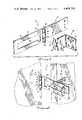
- FIG. 1is an overall view of the safety latch according to the present invention.
- FIG. 2is a perspective view of the safety latch being engaged with the door in a partially open position
- FIG. 3is a perspective view of the safety latch being locked with the door in the closed position
- FIG. 4is a side view with the safety latch being locked with the door in the closed position.
- FIG. 5is a side view of the safety latch being locked with the door in a partially open position
- FIG. 6is a top view of the safety lock.
- the safety latch of the present inventionincludes a jamb plate 13 which is provided with a plurality of holes 15 for attachment to a door jamb (not shown) by conventional screws.
- the screwsmay be of the type that can only be threaded one way as the jamb plate 13 will be exposed when the door is partially opened.
- the jamb plate 13includes a hollow cylindrical end portion 17 which forms part of a hinge in the latch 11.
- the cylindrical portion 17may be divided in two parts or may form a single piece.
- the jamb plate 13is coupled to a pivotable bar 19 which is provided with a cylindrical end portion 21.
- the jamb plateis provided with two cylindrical portions 17 spaced apart a predetermined distance.
- the pivotable bar 19is provided with a cylindrical end portion 21 which has a width substantially less than the distance between the two cylindrical end portions 17 of the jamb plate 13. This construction allows the pivotable bar 19 to be displaced vertically with respect to the jamb plate 13.
- the jamb plate 13 and the pivotable bar 19are coupled at their respective cylindrical end portions 17 and 21 by means of a pin 23.
- Pin 23is provided with a large head 25 at the bottom portion, which is sufficiently large to abut into the end of pivotable bar 19.
- the pin 23may be provided with a flared top 27 to avoid any possible disconnection from the cylindrical end portions 17 and 21. Alternatively and preferably, the pin 23 may be rigidly secured to cylindrical end position 21 thereby making flared top 27 unnecessary. Cylindrical portion 17 thus forms a bearing surface for pin 23.
- a helical spring 29is disposed inbetween the cylindrical end portion 17 and the cylindrical end portion 21 in order to provide a vertical bias on the pivotable bar 19. It is therefore possible to move bar 19 in a vertical position a predetermined distance by exerting pressure on head 25 of pin 23. The spring 29 will normally bias the pivotable bar 19 downwardly.
- the pivotable bar 19is provided with a slot 31 having a first portion 33 of predetermined width which extends longitudinally through pivotable bar 19. Slot 31 also has a second portion 35 which is substantially wider than the width of portion 33.
- the safety latch 11also includes a bracket 36 having a base portion 37, a normal portion 39, and a projecting portion 41.
- the base portion 37is provided with a plurality of holes 43 so that the base portion 37 can be secured to a door with conventional screws.
- the normal portion 39provides an offset for the projecting portion 41 which serves as the locking mechanism of the latch 11.
- the projecting portion 41includes a stem 45 and a head portion 47.
- the head portion 47has a substantially smooth contour until the point at which it joins the stem portion 45. That joint is substantially abrupt and in the preferred embodiment constitutes a 90° angle between the top of the stem portion 45 and the side of the head portion 47.
- the width of the second portion 35 of slot 31must be larger than the width of the head portion 47 of the bracket 36.
- the width of the first portion 33 of slot 31must be greater than the width of stem 45.
- the amount of vertical travel of the pivotable bar 19depends upon the placement of the bracket 36 on the door. This relationship becomes more apparent upon the description of the function of the safety latch 11 with the aids of the figures below.
- FIGS. 2 and 5The locking function with the door partially open is illustrated in FIGS. 2 and 5.
- door 51is opened the predetermined distance from a jamb 57.
- the locking functionis provided between the interaction of the head 47 and a side wall 59 of the first portion 33 of slot 31. Any force on the door 51 would be resisted by the interaction between the head portion 47 of the bracket 35 and the side wall 59 of pivotable bar 19.
- FIGS. 3 and 4Illustrated in FIGS. 3 and 4 is the safety latch in the locking position when the door 51 is in a substantially closed position.
- the locking actionis provided for the juxtaposition of the stem portion 45 to the corner 53 formed in the upper portion of the second portion 35 of the slot.
- the stem portion 45 of the bracket 36is forced against the side wall 55 of the second slotted portion 35 and pivotable bar 19. This situation is made possible by spring 29 which biases pivotable bar 19 downwardly so that the juxtaposition between the stem portion 45 and the side wall portion 55 take place.
- spring 29which biases pivotable bar 19 downwardly so that the juxtaposition between the stem portion 45 and the side wall portion 55 take place.
- bracket 36 on the doormust be such that at the normally biased position of pivotable bar 19 the top of the second portion 35 of slot 31 is substantially at the same level as the top portion of stem 45.
- the versatility of the safety latch 11is enhanced by the ease of operation, as illustrated in FIG. 6.
- the pivotable bar 19would be swung unobstrusively to the side so that it rests substantially flat against the door trim or wall. If the operator desires to lock the door in the closed position he merely pivots bar 19 ninety degrees.
- the head 47 of bracket 36will come into contact with the upper portion of the second portion 35 of slot 33.
- the smooth surface of the head 47will urge the pivotable bar 19 upwards against the bias force of spring 29. Further, rotation will cause bar 19 to rotate past the head portion 47 and the spring 29 will cause the pivotable bar 19 to drop into a locked position on stem 45.
- the present inventionprovides ease of operation in locking and unlocking for handicapped persons by using the elbow or forearm if necessary.
- the safety latchunlike the common safety chain, is easily engaged or disengaged.
Landscapes
- Engineering & Computer Science (AREA)
- Mechanical Engineering (AREA)
- Wing Frames And Configurations (AREA)
Abstract
Description
Claims (4)
Priority Applications (1)
| Application Number | Priority Date | Filing Date | Title |
|---|---|---|---|
| US06/236,810US4408789A (en) | 1981-02-23 | 1981-02-23 | Safety latch for in swinging doors |
Applications Claiming Priority (1)
| Application Number | Priority Date | Filing Date | Title |
|---|---|---|---|
| US06/236,810US4408789A (en) | 1981-02-23 | 1981-02-23 | Safety latch for in swinging doors |
Publications (1)
| Publication Number | Publication Date |
|---|---|
| US4408789Atrue US4408789A (en) | 1983-10-11 |
Family
ID=22891063
Family Applications (1)
| Application Number | Title | Priority Date | Filing Date |
|---|---|---|---|
| US06/236,810Expired - Fee RelatedUS4408789A (en) | 1981-02-23 | 1981-02-23 | Safety latch for in swinging doors |
Country Status (1)
| Country | Link |
|---|---|
| US (1) | US4408789A (en) |
Cited By (15)
| Publication number | Priority date | Publication date | Assignee | Title |
|---|---|---|---|---|
| GB2206374A (en)* | 1987-07-03 | 1989-01-05 | David Kuo | Door restraining assembly |
| GB2240130A (en)* | 1990-01-17 | 1991-07-24 | Bryan Norman Ward | Security device |
| USD319775S (en) | 1989-07-17 | 1991-09-10 | The Stanley Works | Door guard |
| USD319774S (en) | 1989-04-28 | 1991-09-10 | The Stanley Works | Door guard |
| USD320733S (en) | 1988-07-14 | 1991-10-15 | Pearson Stanley W | Anti-theft assembly for video game cabinet access door |
| USD368844S (en) | 1994-04-22 | 1996-04-16 | JWT Corporation | Keyless door lock |
| US20030140761A1 (en)* | 2002-01-25 | 2003-07-31 | Alterra Holdings Corporation | Paper trimmer |
| GB2386639A (en)* | 2002-03-20 | 2003-09-24 | Year Innovations Ltd | A door retaining device |
| GB2416805A (en)* | 2004-07-31 | 2006-02-08 | Bryan James Hill | Access limitation controller |
| US7452011B1 (en) | 2006-09-11 | 2008-11-18 | Eric Lind | Safety latch apparatus |
| US20100289278A1 (en)* | 2009-05-15 | 2010-11-18 | Tang Gordon C | Easily Installed and non-defacing security latch |
| WO2010132044A1 (en)* | 2009-05-15 | 2010-11-18 | Tang Gordon C | Easily installed and non-defacing security latch |
| US20150097381A1 (en)* | 2013-10-03 | 2015-04-09 | Shih-Ming Hwang | Door latch structure |
| US11203884B2 (en)* | 2017-09-14 | 2021-12-21 | Elbee Pty Ltd. | Door handle lock |
| US20240159088A1 (en)* | 2022-11-10 | 2024-05-16 | Flip Lok Llc | Portable door locking device |
Citations (11)
| Publication number | Priority date | Publication date | Assignee | Title |
|---|---|---|---|---|
| US189822A (en)* | 1877-04-17 | Improvement in door-checks | ||
| US236910A (en)* | 1881-01-25 | phillips | ||
| US473785A (en)* | 1892-04-26 | Lawrence samuel | ||
| AT13159B (en)* | 1902-08-12 | 1903-09-10 | Waldherr & Cie Maschf | |
| US1071461A (en)* | 1913-06-13 | 1913-08-26 | Richard G Poston | Hasp. |
| US1336430A (en)* | 1917-04-19 | 1920-04-13 | George H Gustafson | Window-sash attachment |
| US1548744A (en)* | 1924-04-02 | 1925-08-04 | Pratt William Corner | Auxiliary lock for doors and windows |
| US1722736A (en)* | 1928-05-18 | 1929-07-30 | Frederick W Derbyshire | Door guard |
| CH187973A (en)* | 1936-04-06 | 1936-12-15 | Hossmann Ernst | Device on doors to restrict the opening width of the same. |
| GB511988A (en)* | 1938-03-30 | 1939-08-28 | Edward Salthouse | Safety device for use with casement windows |
| US2442733A (en)* | 1945-09-12 | 1948-06-01 | Raiford U Loveless | Door safety latch |
- 1981
- 1981-02-23USUS06/236,810patent/US4408789A/ennot_activeExpired - Fee Related
Patent Citations (11)
| Publication number | Priority date | Publication date | Assignee | Title |
|---|---|---|---|---|
| US189822A (en)* | 1877-04-17 | Improvement in door-checks | ||
| US236910A (en)* | 1881-01-25 | phillips | ||
| US473785A (en)* | 1892-04-26 | Lawrence samuel | ||
| AT13159B (en)* | 1902-08-12 | 1903-09-10 | Waldherr & Cie Maschf | |
| US1071461A (en)* | 1913-06-13 | 1913-08-26 | Richard G Poston | Hasp. |
| US1336430A (en)* | 1917-04-19 | 1920-04-13 | George H Gustafson | Window-sash attachment |
| US1548744A (en)* | 1924-04-02 | 1925-08-04 | Pratt William Corner | Auxiliary lock for doors and windows |
| US1722736A (en)* | 1928-05-18 | 1929-07-30 | Frederick W Derbyshire | Door guard |
| CH187973A (en)* | 1936-04-06 | 1936-12-15 | Hossmann Ernst | Device on doors to restrict the opening width of the same. |
| GB511988A (en)* | 1938-03-30 | 1939-08-28 | Edward Salthouse | Safety device for use with casement windows |
| US2442733A (en)* | 1945-09-12 | 1948-06-01 | Raiford U Loveless | Door safety latch |
Cited By (19)
| Publication number | Priority date | Publication date | Assignee | Title |
|---|---|---|---|---|
| GB2206374A (en)* | 1987-07-03 | 1989-01-05 | David Kuo | Door restraining assembly |
| USD320733S (en) | 1988-07-14 | 1991-10-15 | Pearson Stanley W | Anti-theft assembly for video game cabinet access door |
| USD319774S (en) | 1989-04-28 | 1991-09-10 | The Stanley Works | Door guard |
| USD319775S (en) | 1989-07-17 | 1991-09-10 | The Stanley Works | Door guard |
| GB2240130A (en)* | 1990-01-17 | 1991-07-24 | Bryan Norman Ward | Security device |
| USD368844S (en) | 1994-04-22 | 1996-04-16 | JWT Corporation | Keyless door lock |
| US7299731B2 (en)* | 2002-01-25 | 2007-11-27 | Alterra Holdings Corporation | Paper trimmer |
| US20030140761A1 (en)* | 2002-01-25 | 2003-07-31 | Alterra Holdings Corporation | Paper trimmer |
| US20070261529A1 (en)* | 2002-01-25 | 2007-11-15 | Alterra Holdings Corporation | Paper trimmer |
| GB2386639A (en)* | 2002-03-20 | 2003-09-24 | Year Innovations Ltd | A door retaining device |
| GB2416805A (en)* | 2004-07-31 | 2006-02-08 | Bryan James Hill | Access limitation controller |
| GB2416805B (en)* | 2004-07-31 | 2009-06-24 | Bryan James Hill | Access limitation controller |
| US7452011B1 (en) | 2006-09-11 | 2008-11-18 | Eric Lind | Safety latch apparatus |
| US20100289278A1 (en)* | 2009-05-15 | 2010-11-18 | Tang Gordon C | Easily Installed and non-defacing security latch |
| WO2010132044A1 (en)* | 2009-05-15 | 2010-11-18 | Tang Gordon C | Easily installed and non-defacing security latch |
| US20150097381A1 (en)* | 2013-10-03 | 2015-04-09 | Shih-Ming Hwang | Door latch structure |
| US9309702B2 (en)* | 2013-10-03 | 2016-04-12 | Shih-Ming Hwang | Door latch structure |
| US11203884B2 (en)* | 2017-09-14 | 2021-12-21 | Elbee Pty Ltd. | Door handle lock |
| US20240159088A1 (en)* | 2022-11-10 | 2024-05-16 | Flip Lok Llc | Portable door locking device |
Similar Documents
| Publication | Publication Date | Title |
|---|---|---|
| US4408789A (en) | Safety latch for in swinging doors | |
| US5839767A (en) | Pick-resistant lock actuator | |
| US4777765A (en) | Adjustable width doorway safety gate apparatus | |
| US5983680A (en) | Door locking device | |
| US4283882A (en) | Safety flush bolt entrance door system | |
| US5890753A (en) | Lock mechanism | |
| US5595409A (en) | Gliding door latch assembly | |
| US5224297A (en) | Sliding door and latching/locking assembly | |
| US7373755B2 (en) | Safety gate assembly | |
| US5501492A (en) | Deadbolt with infinitely adjustable backset | |
| US5865480A (en) | Sliding door security and child safety latch | |
| US4715200A (en) | Locking device for a door lock | |
| US5007263A (en) | Security device | |
| US5083398A (en) | Remote window lock | |
| US5395143A (en) | Post assembly permitting only limited opening of a portal | |
| US4027907A (en) | Security chain lock for doors | |
| US4318559A (en) | Lock for sliding members | |
| US4878701A (en) | Portable door lock | |
| US6068306A (en) | Window locking arrangement | |
| US4691950A (en) | Device for detachably securing pivotally connected members in a predetermined relative position | |
| GB2041051A (en) | Baby gates | |
| US5098138A (en) | Building closure security device | |
| US5472246A (en) | Independent dual deadbolt locking mechanism | |
| US6139074A (en) | Window locking system | |
| US6454323B1 (en) | High-security auxiliary door lock |
Legal Events
| Date | Code | Title | Description |
|---|---|---|---|
| MAFP | Maintenance fee payment | Free format text:PAYMENT OF MAINTENANCE FEE, 4TH YEAR, PL 96-517 (ORIGINAL EVENT CODE: M170); ENTITY STATUS OF PATENT OWNER: SMALL ENTITY Year of fee payment:4 | |
| FEPP | Fee payment procedure | Free format text:SURCHARGE FOR LATE PAYMENT, PL 96-517 (ORIGINAL EVENT CODE: M176); ENTITY STATUS OF PATENT OWNER: SMALL ENTITY | |
| MAFP | Maintenance fee payment | Free format text:PAYMENT OF MAINTENANCE FEE, 8TH YEAR, PL 96-517 (ORIGINAL EVENT CODE: M171); ENTITY STATUS OF PATENT OWNER: SMALL ENTITY Year of fee payment:8 | |
| FEPP | Fee payment procedure | Free format text:MAINTENANCE FEE REMINDER MAILED (ORIGINAL EVENT CODE: REM.); ENTITY STATUS OF PATENT OWNER: SMALL ENTITY | |
| LAPS | Lapse for failure to pay maintenance fees | ||
| FEPP | Fee payment procedure | Free format text:SURCHARGE FOR LATE PAYMENT, SMALL ENTITY (ORIGINAL EVENT CODE: M286); ENTITY STATUS OF PATENT OWNER: SMALL ENTITY | |
| MAFP | Maintenance fee payment | Free format text:PAYMENT OF MAINTENANCE FEE, 12TH YR, SMALL ENTITY (ORIGINAL EVENT CODE: M285); ENTITY STATUS OF PATENT OWNER: SMALL ENTITY Year of fee payment:12 | |
| FP | Lapsed due to failure to pay maintenance fee | Effective date:19951011 | |
| STCH | Information on status: patent discontinuation | Free format text:PATENT EXPIRED DUE TO NONPAYMENT OF MAINTENANCE FEES UNDER 37 CFR 1.362 |