US4408607A - Capacitive energy source and circuitry for powering medical apparatus - Google Patents
Capacitive energy source and circuitry for powering medical apparatusDownload PDFInfo
- Publication number
- US4408607A US4408607AUS06/253,308US25330881AUS4408607AUS 4408607 AUS4408607 AUS 4408607AUS 25330881 AUS25330881 AUS 25330881AUS 4408607 AUS4408607 AUS 4408607A
- Authority
- US
- United States
- Prior art keywords
- capacitor
- switch
- power supply
- voltage
- battery
- Prior art date
- Legal status (The legal status is an assumption and is not a legal conclusion. Google has not performed a legal analysis and makes no representation as to the accuracy of the status listed.)
- Expired - Fee Related
Links
- 239000003990capacitorSubstances0.000claimsabstractdescription83
- 239000003112inhibitorSubstances0.000claimsabstractdescription7
- 230000002146bilateral effectEffects0.000claimsdescription4
- 230000001105regulatory effectEffects0.000claimsdescription3
- 239000000126substanceSubstances0.000claimsdescription3
- 238000007599dischargingMethods0.000abstractdescription2
- 239000004020conductorSubstances0.000description39
- 238000004804windingMethods0.000description13
- XUIMIQQOPSSXEZ-UHFFFAOYSA-NSiliconChemical compound[Si]XUIMIQQOPSSXEZ-UHFFFAOYSA-N0.000description6
- 229910052710siliconInorganic materials0.000description6
- 239000010703siliconSubstances0.000description6
- 238000010586diagramMethods0.000description3
- WHXSMMKQMYFTQS-UHFFFAOYSA-NLithiumChemical compound[Li]WHXSMMKQMYFTQS-UHFFFAOYSA-N0.000description2
- OJIJEKBXJYRIBZ-UHFFFAOYSA-Ncadmium nickelChemical compound[Ni].[Cd]OJIJEKBXJYRIBZ-UHFFFAOYSA-N0.000description2
- 239000002775capsuleSubstances0.000description2
- 230000003111delayed effectEffects0.000description2
- 229910052744lithiumInorganic materials0.000description2
- 230000007423decreaseEffects0.000description1
- 238000005516engineering processMethods0.000description1
- 238000004880explosionMethods0.000description1
- 239000007943implantSubstances0.000description1
- 230000001939inductive effectEffects0.000description1
- 238000000034methodMethods0.000description1
- 238000010943off-gassingMethods0.000description1
- 238000007493shaping processMethods0.000description1
- 238000001356surgical procedureMethods0.000description1
Images

Classifications
- A—HUMAN NECESSITIES
- A61—MEDICAL OR VETERINARY SCIENCE; HYGIENE
- A61N—ELECTROTHERAPY; MAGNETOTHERAPY; RADIATION THERAPY; ULTRASOUND THERAPY
- A61N1/00—Electrotherapy; Circuits therefor
- A61N1/18—Applying electric currents by contact electrodes
- A61N1/32—Applying electric currents by contact electrodes alternating or intermittent currents
- A61N1/36—Applying electric currents by contact electrodes alternating or intermittent currents for stimulation
- A61N1/372—Arrangements in connection with the implantation of stimulators
- A61N1/378—Electrical supply
- A61N1/3787—Electrical supply from an external energy source
Definitions
- This inventionrelates to the field of medical electronics, and particularly to apparatus for supplying power to devices surgically implanted in living bodies to continue in operation over extended intervals.
- the present inventiontakes advantage of a new technology in capacitors by making a charged capacitor the principal power source for implantable devices, and providing for charging the capacitor from outside the living body.
- the very low current drain demanded by implantable devices, and the large capacitance and low leakage of the new capacitors, in acceptably small physical formmakes the use of charged capacitors as voltage sources feasible and practical, with the advantage that charging intervals for such capacitors are very much shorter than those for electro-chemical batteries. For some applications it may be necessary to isolate the device from the capacitor during the short charging interval. If the device in question cannot tolerate short-term power interruptions, an implanted backup power source may be provided in the form of an electro-chemical battery. The life of such a battery is greatly extended when it is only used for brief intervals during charging of a capacitor as a principal power source.
- the inventionincludes implantable charging circuitry, and may also include means preventing the voltage rating of the capacitor from being exceeded, either by pressure responsive or other physical means, or by the electronic circuitry itself.
- FIG. 1is a block diagram of an embodiment of the invention
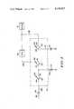
- FIG. 2is a circuit diagram of a first embodiment of an implantable power supply circuitry according to the invention.
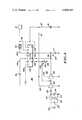
- FIG. 3shows a second embodiment of the invention adapted for use where the capacitor must be isolated from the powered device during charging, and yet no interruption of power to an implanted device can be tolerated;
- FIG. 4is a fragmentary schematic of a detail of FIG. 3.
- FIG. 1showing an implantable power supply according to the invention in block diagram.
- capacitor 20may be encapsulated and a pressure override 27 may be actuated should the pressure in the capsule rise unduly.
- Diode 26functions to prevent capacitor 20 from discharging through the charging circuitry when charging is not taking place.
- FIG. 2shows that voltage source 23 comprises a secondary winding 30 of a transformer 31, the removable primary winding 32 of which is external to the body in which the remaining components are implanted, for inductive energization of the charging circuitry from a source 23 of radio frequency energy of a chosen frequency. Windings 30 and 32 are preferably tuned by capacitors 34 and 35, respectively. Source 23 also includes a rectifying diode 36 so that the voltage on a conductor 37 is unidirectional.
- Regulator 24comprises a resistor 40, a Zener diode 41, a transistor 42 having a base 43, an emitter 44, and a collector 45.
- the junction point 46 between resistor 40 and Zener 41is connected to base 43 so that the current flowing through the transistor from conductor 37 to an output conductor 47 remains constant.
- Over-voltage inhibitor 25comprises a voltage comparator 50 powered from conductor 47 and having a first input 51 from a voltage divider 52 made up of resistors 53 and 54, and a second input 55 from a voltage divider 56 made up of resistors 57 and 58, the latter being shunted by a Zener diode 59 to stabilize the second input to the comparator.
- the output of comparator 50is supplied to the gate electrode 60 of a silicon controlled rectifier 61 having an anode 62 connected to conductor 47 and a cathode 63 grounded through a resistor 64.
- the output of inhibitor 25is supplied to diode 26 through conductors 47 and 48, and thence to capacitor 20 and regulator 22 by conductor 49.
- Pressure override 27may comprise a silicon controlled rectifier 70 having an anode 71 connected to conductor 47, a cathode 72 connected to ground through a resistor 73, and a gating electrode 74 which may be connected to anode 71 when a normally open pressure switch 75 is closed by a mechanical connection 76 to the capsule of capacitor 20. Pressure override 27 is connected to diode 26 through a conductor 48.
- capacitor 20During use of capacitor 20 as a power source, the voltage on conductor 49 gradually decreases. When charging is undertaken, the voltage on conductor 48 must be greater than that of conductor 49 so that diode 26 can conduct the charging current. As charging continues, the voltage on conductor 48 must remain higher than that on conductor 49. It is understood that the voltage rating of capacitor 20 is chosen to be greater than the voltage which the capacitor is to supply as a power supply, but inadvertent overcharging of the capacitor is to be avoided. It is a characteristic of these capacitors that their rating voltage must not be exceeded, otherwise excessive out-gassing and even explosion will occur.
- FIG. 3shows how the invention may be applied when the implanted device being powered cannot remain connected to said capacitor during charging, and cannot tolerate a power interruption.
- elements 20, 21, 22, and 26are as previously described, but conductor 49 is interrupted by an implanted make-before-break switching arrangement 80 and appears as conductors 49a, 49b, and 49c.
- a lithium battery 81which is to replace capacitor 20 as a power source during the charging period. More complete details of the switching arrangement 80 are given in FIG. 4, but FIG. 3 shows schematically the switching functions accomplished.
- a first switch 82has a movable contact 83, a normally closed contact 84, and a normally open contact 85.
- a second switch 86has a movable contact 87, a normally closed contact 90 and a normally open contact 91.
- a third switch 92has a movable contact 93, a normally closed contact 94, and a movable contact 95.
- Contact 83is connected to diode 26 by conductor 49a.
- Contacts 85 and 87are connected to capacitor 20 by conductor 49c.
- Contact 90is connected to regulator 22 by conductor 49b.
- Contact 93is connected to the positive pole of battery 81 by conductors 96 and 97, and contact 95 is connected to device 21 by conductor 98.
- capacitor 20is connected to supply power to regulator 22 through switch 86, battery 81 is isolated by switch 92, and rectifier 26 is isolated by switch 82.
- the switchesare operated generally simultaneously, but in such a manner that switch 92 closes, to connect battery 81 to device 21, before switch 86 opens, to disconnect the capacitor from the device, so that battery 81 replaces capacitor 20 as a source of power for device 21 without any interruption.
- Switch 82then connects the capacitor for charging, as described in connection with FIG. 2. Reverse operation of the switches disconnects the capacitor from the charging surface and connects it to the device before battery 81 is disconnected.
- FIG. 4shows switching arrangement 80 in more detail.
- the actual switching functionsare performed by a quad bilateral switch 100, preferably a CD 4016M/CD or 4016C.
- Switch 100is controlled in its operation by circuit 101 including first and second operational amplifiers or Schmitt trigger inverters 102 and 103, a first timer circuit 104 including a resistor 105 and a capacitor 106, and a second timer circuit 107 including a resistor 110 and a capacitor 111, a diode 112, and the secondary winding 113, tuned by a capacitor 114, of a transformer 115.
- the primary winding 116 of transformer 115is tuned by a capacitor 117. Winding 116 is outside the patient's body and is energized by a source 120 of radio frequency energy of a frequency different from that energizing transformer 31.
- Schmitt trigger pulse shaping circuits 102 and 103are energized from battery 81 through conductors 97, 121, 122, and 123 to supply control voltages to conductors 124, 125, and 126 relating to switch 100.
- the relation between FIGS. 3 and 4is as follows. When a signal is supplied on conductor 124, conductor 49a is connected to conductor 49c, in the function of switch 82. When a signal is supplied on conductor 125, conductor 96 is connected to conductor 98, in the function of switch 92. When a signal is supplied on conductor 126, conductor 49c is disconnected from conductor 49b, in the function of switch 86.
- transformer winding 116When it is desired to charge capacitor 20, transformer winding 116 is apposed to secondary winding 133, and source 120 is energized. An induced voltage is supplied by winding 113, rectified by diode 112, and supplied to inverter 102, which supplies a negative-going pulse to timing circuit 104, where the pulse is delayed. The negative-going pulse from inverter 102 is also supplied without delay to inverter 103, which, in turn, supplies a positive-going pulse to conductor 125 directly, and to timing circuit 107, where it is delayed.
- source 120is deenergized and the implanted circuit returns to its original condition, in which the now fully charged capacitor is connected to power the device and the battery is disconnected.
- the inventioncomprises apparatus whereby a charged capacitor may function as the power supply for a medical device implanted in a patient, and may be charged from a source external to the patient, and whereby an implanted battery may be substituted for the capacitor during charge intervals if the nature of the device requires uninterrupted energization.
Landscapes
- Health & Medical Sciences (AREA)
- Engineering & Computer Science (AREA)
- Biomedical Technology (AREA)
- Nuclear Medicine, Radiotherapy & Molecular Imaging (AREA)
- Radiology & Medical Imaging (AREA)
- Life Sciences & Earth Sciences (AREA)
- Animal Behavior & Ethology (AREA)
- General Health & Medical Sciences (AREA)
- Public Health (AREA)
- Veterinary Medicine (AREA)
- Charge And Discharge Circuits For Batteries Or The Like (AREA)
Abstract
Description
Claims (16)
Priority Applications (1)
| Application Number | Priority Date | Filing Date | Title |
|---|---|---|---|
| US06/253,308US4408607A (en) | 1981-04-13 | 1981-04-13 | Capacitive energy source and circuitry for powering medical apparatus |
Applications Claiming Priority (1)
| Application Number | Priority Date | Filing Date | Title |
|---|---|---|---|
| US06/253,308US4408607A (en) | 1981-04-13 | 1981-04-13 | Capacitive energy source and circuitry for powering medical apparatus |
Publications (1)
| Publication Number | Publication Date |
|---|---|
| US4408607Atrue US4408607A (en) | 1983-10-11 |
Family
ID=22959733
Family Applications (1)
| Application Number | Title | Priority Date | Filing Date |
|---|---|---|---|
| US06/253,308Expired - Fee RelatedUS4408607A (en) | 1981-04-13 | 1981-04-13 | Capacitive energy source and circuitry for powering medical apparatus |
Country Status (1)
| Country | Link |
|---|---|
| US (1) | US4408607A (en) |
Cited By (37)
| Publication number | Priority date | Publication date | Assignee | Title |
|---|---|---|---|---|
| US4599523A (en)* | 1984-02-16 | 1986-07-08 | Intermedics, Inc. | Power priority system |
| GB2239802A (en)* | 1990-01-09 | 1991-07-17 | Univ Ottawa | Transcutaneous energy transfer device |
| US5279292A (en)* | 1991-02-13 | 1994-01-18 | Implex Gmbh | Charging system for implantable hearing aids and tinnitus maskers |
| US5350413A (en)* | 1990-06-21 | 1994-09-27 | The University Of Ottawa | Transcutaneous energy transfer device |
| US5519295A (en)* | 1994-04-06 | 1996-05-21 | Honeywell Inc. | Electrically operated actuator having a capacitor storing energy for returning the actuator to a preferred position upon power failure |
| WO1996020754A1 (en)* | 1995-01-04 | 1996-07-11 | Plexus, Inc. | Implantable stimulator with replenishable, high value capacitive power source and method therefor |
| US5733313A (en)* | 1996-08-01 | 1998-03-31 | Exonix Corporation | RF coupled, implantable medical device with rechargeable back-up power source |
| US5757167A (en)* | 1996-07-12 | 1998-05-26 | Cardiac Pacemakers, Inc. | Voltage regulator |
| WO1999042173A1 (en) | 1998-02-23 | 1999-08-26 | Medtronic, Inc. | Rf coupled, implantable medical device with rechargeable back-up power source |
| US6099495A (en)* | 1998-04-30 | 2000-08-08 | Medtronic, Inc. | Implantable electrical transducer powered from capacitive storage energy source |
| US6167309A (en)* | 1997-09-15 | 2000-12-26 | Cardiac Pacemakers, Inc. | Method for monitoring end of life for battery |
| US6456883B1 (en) | 2000-04-26 | 2002-09-24 | Medtronic, Inc. | Apparatus and method for allowing immediate retrieval for information and identification from an implantable medical device having a depleted power source |
| US20030038016A1 (en)* | 2001-08-24 | 2003-02-27 | Nagi Hilal | Tap switch for frequency response and partial discharge measurement |
| US6577900B1 (en) | 2001-05-29 | 2003-06-10 | Pacesetter, Inc. | High speed telemetry system |
| US20030176897A1 (en)* | 2001-04-10 | 2003-09-18 | Cardiac Pacemakers, Inc. | System and method for measuring battery current |
| US6631293B2 (en) | 1997-09-15 | 2003-10-07 | Cardiac Pacemakers, Inc. | Method for monitoring end of life for battery |
| US6713894B1 (en)* | 1997-12-11 | 2004-03-30 | Bayerische Motoren Werke Aktiengesellschaft | Device for supplying electricity to a motor vehicle |
| US20040064154A1 (en)* | 2002-09-30 | 2004-04-01 | Norton John D. | Apparatus and method for optimizing capacitor charge in a medical device |
| US20050075697A1 (en)* | 2003-10-02 | 2005-04-07 | Medtronic, Inc. | External power source for an implantable medical device having an adjustable carrier frequency and system and method related therefore |
| US20050088145A1 (en)* | 2003-10-23 | 2005-04-28 | Robert Loch | Battery charge indicator such as for an implantable medical device |
| EP1626493A1 (en)* | 2004-08-11 | 2006-02-15 | Stmicroelectronics Sa | Capacitive power supply |
| US20060034943A1 (en)* | 2003-10-31 | 2006-02-16 | Technology Innovations Llc | Process for treating a biological organism |
| US20070055308A1 (en)* | 2005-09-06 | 2007-03-08 | Haller Matthew I | Ultracapacitor powered implantable pulse generator with dedicated power supply |
| US20070114964A1 (en)* | 2005-11-23 | 2007-05-24 | Stmicroelectronics S.A. | Control of a triac for the starting of a motor |
| US20080140139A1 (en)* | 2000-11-22 | 2008-06-12 | Heinrich Stephen D | Apparatus for detecting and treating ventricular arrhythmia |
| US20090096288A1 (en)* | 2007-10-10 | 2009-04-16 | Ams Research Corporation | Powering devices having low and high voltage circuits |
| US20100030153A1 (en)* | 2006-10-11 | 2010-02-04 | Mallinckrodt Inc. | Injector Having Low Input Power |
| US20100114249A1 (en)* | 2008-10-31 | 2010-05-06 | Medtronic, Inc. | Non-hermetic direct current interconnect |
| US8004231B2 (en) | 2005-11-23 | 2011-08-23 | Stmicroelectronics S.A. | Control of a triac for the starting of a motor |
| US8086313B2 (en) | 2002-12-09 | 2011-12-27 | Medtronic, Inc. | Implantable medical device with anti-infection agent |
| US8280478B2 (en) | 2004-04-29 | 2012-10-02 | Medtronic, Inc. | Evaluation of implantation site for implantation of implantable medical device |
| US8397732B2 (en) | 2002-12-09 | 2013-03-19 | Medtronic, Inc. | Implantation of low-profile implantable medical device |
| US8764621B2 (en) | 2011-07-11 | 2014-07-01 | Vascor, Inc. | Transcutaneous power transmission and communication for implanted heart assist and other devices |
| US9084901B2 (en) | 2006-04-28 | 2015-07-21 | Medtronic, Inc. | Cranial implant |
| US9162072B2 (en) | 2004-04-30 | 2015-10-20 | Medtronic, Inc. | Implantable medical device with lubricious material |
| US9345883B2 (en) | 2014-02-14 | 2016-05-24 | Boston Scientific Neuromodulation Corporation | Rechargeable-battery implantable medical device having a primary battery active during a rechargeable-battery undervoltage condition |
| US9694192B2 (en) | 2013-10-04 | 2017-07-04 | Boston Scientific Neuromodulation Corporation | Implantable medical device with a primary and rechargeable battery |
Citations (6)
| Publication number | Priority date | Publication date | Assignee | Title |
|---|---|---|---|---|
| US3209081A (en)* | 1961-10-02 | 1965-09-28 | Behrman A Ducote | Subcutaneously implanted electronic device |
| US3258013A (en)* | 1963-07-01 | 1966-06-28 | Zenith Radio Corp | Defibrillators |
| US3888261A (en)* | 1973-12-07 | 1975-06-10 | Medtronic Inc | Time shared stimulator |
| US4019518A (en)* | 1975-08-11 | 1977-04-26 | Medtronic, Inc. | Electrical stimulation system |
| US4096866A (en)* | 1976-04-30 | 1978-06-27 | The Johns Hopkins University | Rechargeable body tissue stimulator with back-up battery and pulse generator |
| US4275739A (en)* | 1979-01-26 | 1981-06-30 | The Johns Hopkins University | Charge control switch responsive to cell casing deflection |
- 1981
- 1981-04-13USUS06/253,308patent/US4408607A/ennot_activeExpired - Fee Related
Patent Citations (6)
| Publication number | Priority date | Publication date | Assignee | Title |
|---|---|---|---|---|
| US3209081A (en)* | 1961-10-02 | 1965-09-28 | Behrman A Ducote | Subcutaneously implanted electronic device |
| US3258013A (en)* | 1963-07-01 | 1966-06-28 | Zenith Radio Corp | Defibrillators |
| US3888261A (en)* | 1973-12-07 | 1975-06-10 | Medtronic Inc | Time shared stimulator |
| US4019518A (en)* | 1975-08-11 | 1977-04-26 | Medtronic, Inc. | Electrical stimulation system |
| US4096866A (en)* | 1976-04-30 | 1978-06-27 | The Johns Hopkins University | Rechargeable body tissue stimulator with back-up battery and pulse generator |
| US4275739A (en)* | 1979-01-26 | 1981-06-30 | The Johns Hopkins University | Charge control switch responsive to cell casing deflection |
Non-Patent Citations (1)
| Title |
|---|
| NEC Electron, Inc. publication, "Super Capacitors".* |
Cited By (75)
| Publication number | Priority date | Publication date | Assignee | Title |
|---|---|---|---|---|
| US4599523A (en)* | 1984-02-16 | 1986-07-08 | Intermedics, Inc. | Power priority system |
| GB2239802A (en)* | 1990-01-09 | 1991-07-17 | Univ Ottawa | Transcutaneous energy transfer device |
| GB2239802B (en)* | 1990-01-09 | 1994-01-05 | Univ Ottawa | Transcutaneous energy transfer device |
| US5350413A (en)* | 1990-06-21 | 1994-09-27 | The University Of Ottawa | Transcutaneous energy transfer device |
| US5279292A (en)* | 1991-02-13 | 1994-01-18 | Implex Gmbh | Charging system for implantable hearing aids and tinnitus maskers |
| US5519295A (en)* | 1994-04-06 | 1996-05-21 | Honeywell Inc. | Electrically operated actuator having a capacitor storing energy for returning the actuator to a preferred position upon power failure |
| US5807397A (en)* | 1995-01-04 | 1998-09-15 | Plexus, Inc. | Implantable stimulator with replenishable, high value capacitive power source and method therefor |
| WO1996020754A1 (en)* | 1995-01-04 | 1996-07-11 | Plexus, Inc. | Implantable stimulator with replenishable, high value capacitive power source and method therefor |
| US5591217A (en)* | 1995-01-04 | 1997-01-07 | Plexus, Inc. | Implantable stimulator with replenishable, high value capacitive power source and method therefor |
| AU691778B2 (en)* | 1995-01-04 | 1998-05-21 | Plexus, Inc. | Implantable stimulator with replenishable high value capacitive power source and method therefor |
| US5769877A (en)* | 1995-01-04 | 1998-06-23 | Plexus, Inc. | High value capacitive, replenishable power source |
| US5757167A (en)* | 1996-07-12 | 1998-05-26 | Cardiac Pacemakers, Inc. | Voltage regulator |
| US5847551A (en)* | 1996-07-12 | 1998-12-08 | Cardiac Pacemakers, Inc. | Voltage regulator |
| USRE42682E1 (en)* | 1996-08-01 | 2011-09-06 | Medtronic, Inc. | RF coupled, implantable medical device with rechargeable back-up power source |
| US5733313A (en)* | 1996-08-01 | 1998-03-31 | Exonix Corporation | RF coupled, implantable medical device with rechargeable back-up power source |
| US20070265672A1 (en)* | 1997-09-15 | 2007-11-15 | Cardiac Pacemakers, Inc. | Method for monitoring end of life for battery |
| US6167309A (en)* | 1997-09-15 | 2000-12-26 | Cardiac Pacemakers, Inc. | Method for monitoring end of life for battery |
| US7515962B2 (en) | 1997-09-15 | 2009-04-07 | Cardiac Pacemakers, Inc. | Method for monitoring end of life for battery |
| US7251527B2 (en) | 1997-09-15 | 2007-07-31 | Cardiac Pacemakers, Inc. | Method for monitoring end of life for battery |
| US7580749B2 (en) | 1997-09-15 | 2009-08-25 | Cardiac Pacemakers, Inc. | Method for monitoring end of life for battery |
| US20040073264A1 (en)* | 1997-09-15 | 2004-04-15 | Cardiac Pacemakers, Inc. | Method for monitoring end of life for battery |
| US6654640B2 (en) | 1997-09-15 | 2003-11-25 | Cardiac Pacemakers, Inc. | Method for monitoring end of life for battery |
| US20040024426A1 (en)* | 1997-09-15 | 2004-02-05 | Cardiac Pacemakers, Inc. | Method for monitoring end of life for battery |
| US6631293B2 (en) | 1997-09-15 | 2003-10-07 | Cardiac Pacemakers, Inc. | Method for monitoring end of life for battery |
| US6713894B1 (en)* | 1997-12-11 | 2004-03-30 | Bayerische Motoren Werke Aktiengesellschaft | Device for supplying electricity to a motor vehicle |
| WO1999042173A1 (en) | 1998-02-23 | 1999-08-26 | Medtronic, Inc. | Rf coupled, implantable medical device with rechargeable back-up power source |
| US6099495A (en)* | 1998-04-30 | 2000-08-08 | Medtronic, Inc. | Implantable electrical transducer powered from capacitive storage energy source |
| US6456883B1 (en) | 2000-04-26 | 2002-09-24 | Medtronic, Inc. | Apparatus and method for allowing immediate retrieval for information and identification from an implantable medical device having a depleted power source |
| US9022962B2 (en) | 2000-11-22 | 2015-05-05 | Boston Scientific Scimed, Inc. | Apparatus for detecting and treating ventricular arrhythmia |
| US20080140139A1 (en)* | 2000-11-22 | 2008-06-12 | Heinrich Stephen D | Apparatus for detecting and treating ventricular arrhythmia |
| US20050143782A1 (en)* | 2001-04-10 | 2005-06-30 | Cardiac Pacemakers, Inc. | System and method for measuring battery current |
| US6885894B2 (en) | 2001-04-10 | 2005-04-26 | Cardiac Pacemakers, Inc. | System and method for measuring battery current |
| US20030176897A1 (en)* | 2001-04-10 | 2003-09-18 | Cardiac Pacemakers, Inc. | System and method for measuring battery current |
| US7191005B2 (en) | 2001-04-10 | 2007-03-13 | Cardiac Pacemakers, Inc. | System and method for measuring battery current |
| US6577900B1 (en) | 2001-05-29 | 2003-06-10 | Pacesetter, Inc. | High speed telemetry system |
| US20030038016A1 (en)* | 2001-08-24 | 2003-02-27 | Nagi Hilal | Tap switch for frequency response and partial discharge measurement |
| WO2003019211A1 (en)* | 2001-08-24 | 2003-03-06 | Abb Technology Ag | Tap switch for frequency response and partial discharge measurement |
| US6580276B2 (en)* | 2001-08-24 | 2003-06-17 | Abb Technology Ag | Tap switch for frequency response and partial discharge measurement |
| US8195291B2 (en) | 2002-09-30 | 2012-06-05 | Medtronic, Inc. | Apparatus and method for optimizing capacitor charge in a medical device |
| WO2004030749A1 (en)* | 2002-09-30 | 2004-04-15 | Medtronic, Inc. | Apparatus and method for optimizing capacitor charge in a medical device |
| US20060195148A1 (en)* | 2002-09-30 | 2006-08-31 | Norton John D | Apparatus and method for optimizing capacitor charge in a medical device |
| US20040064154A1 (en)* | 2002-09-30 | 2004-04-01 | Norton John D. | Apparatus and method for optimizing capacitor charge in a medical device |
| US8397732B2 (en) | 2002-12-09 | 2013-03-19 | Medtronic, Inc. | Implantation of low-profile implantable medical device |
| US8666497B2 (en) | 2002-12-09 | 2014-03-04 | Medtronic, Inc. | Coupling module of a modular implantable medical device |
| US8086313B2 (en) | 2002-12-09 | 2011-12-27 | Medtronic, Inc. | Implantable medical device with anti-infection agent |
| US8630717B2 (en) | 2003-10-02 | 2014-01-14 | Medtronic, Inc. | External power source for an implantable medical device having an adjustable carrier frequency and system and method related therefore |
| US20050075697A1 (en)* | 2003-10-02 | 2005-04-07 | Medtronic, Inc. | External power source for an implantable medical device having an adjustable carrier frequency and system and method related therefore |
| US8140168B2 (en)* | 2003-10-02 | 2012-03-20 | Medtronic, Inc. | External power source for an implantable medical device having an adjustable carrier frequency and system and method related therefore |
| US6940255B2 (en) | 2003-10-23 | 2005-09-06 | Cardiac Pacemakers, Inc. | Battery charge indicator such as for an implantable medical device |
| US20050088145A1 (en)* | 2003-10-23 | 2005-04-28 | Robert Loch | Battery charge indicator such as for an implantable medical device |
| US20060034943A1 (en)* | 2003-10-31 | 2006-02-16 | Technology Innovations Llc | Process for treating a biological organism |
| US8280478B2 (en) | 2004-04-29 | 2012-10-02 | Medtronic, Inc. | Evaluation of implantation site for implantation of implantable medical device |
| US9162072B2 (en) | 2004-04-30 | 2015-10-20 | Medtronic, Inc. | Implantable medical device with lubricious material |
| EP1626493A1 (en)* | 2004-08-11 | 2006-02-15 | Stmicroelectronics Sa | Capacitive power supply |
| US20060034109A1 (en)* | 2004-08-11 | 2006-02-16 | Ghafour Benabdelaziz | Capacitive power supply circuit and method |
| US7483280B2 (en) | 2004-08-11 | 2009-01-27 | Stmicroelectronics Sa | Capacitive power supply circuit and method |
| US20070055308A1 (en)* | 2005-09-06 | 2007-03-08 | Haller Matthew I | Ultracapacitor powered implantable pulse generator with dedicated power supply |
| US8175717B2 (en) | 2005-09-06 | 2012-05-08 | Boston Scientific Neuromodulation Corporation | Ultracapacitor powered implantable pulse generator with dedicated power supply |
| WO2007030496A1 (en) | 2005-09-06 | 2007-03-15 | Advanced Bionics Corporation | Ultracapacitor powered implantable pulse generator with dedicated power supply |
| US8004231B2 (en) | 2005-11-23 | 2011-08-23 | Stmicroelectronics S.A. | Control of a triac for the starting of a motor |
| US7514897B2 (en)* | 2005-11-23 | 2009-04-07 | Stmicroelectronics S.A. | Control of a triac for the starting of a motor |
| US20070114964A1 (en)* | 2005-11-23 | 2007-05-24 | Stmicroelectronics S.A. | Control of a triac for the starting of a motor |
| US9504402B2 (en) | 2006-04-28 | 2016-11-29 | Medtronic, Inc. | Cranial implant |
| US9084901B2 (en) | 2006-04-28 | 2015-07-21 | Medtronic, Inc. | Cranial implant |
| US20100030153A1 (en)* | 2006-10-11 | 2010-02-04 | Mallinckrodt Inc. | Injector Having Low Input Power |
| US8657787B2 (en) | 2006-10-11 | 2014-02-25 | Mallinckrodt Llc | Injector having low input power |
| US20090096288A1 (en)* | 2007-10-10 | 2009-04-16 | Ams Research Corporation | Powering devices having low and high voltage circuits |
| US8044536B2 (en) | 2007-10-10 | 2011-10-25 | Ams Research Corporation | Powering devices having low and high voltage circuits |
| US20100114249A1 (en)* | 2008-10-31 | 2010-05-06 | Medtronic, Inc. | Non-hermetic direct current interconnect |
| US9393432B2 (en) | 2008-10-31 | 2016-07-19 | Medtronic, Inc. | Non-hermetic direct current interconnect |
| US8764621B2 (en) | 2011-07-11 | 2014-07-01 | Vascor, Inc. | Transcutaneous power transmission and communication for implanted heart assist and other devices |
| US9308303B2 (en) | 2011-07-11 | 2016-04-12 | Vascor, Inc. | Transcutaneous power transmission and communication for implanted heart assist and other devices |
| US9694192B2 (en) | 2013-10-04 | 2017-07-04 | Boston Scientific Neuromodulation Corporation | Implantable medical device with a primary and rechargeable battery |
| US9345883B2 (en) | 2014-02-14 | 2016-05-24 | Boston Scientific Neuromodulation Corporation | Rechargeable-battery implantable medical device having a primary battery active during a rechargeable-battery undervoltage condition |
| US9814882B2 (en) | 2014-02-14 | 2017-11-14 | Boston Scientific Neuromodulation Corporation | Rechargeable-battery implantable medical device having a primary battery active during a rechargeable-battery undervoltage condition |
Similar Documents
| Publication | Publication Date | Title |
|---|---|---|
| US4408607A (en) | Capacitive energy source and circuitry for powering medical apparatus | |
| US7126310B1 (en) | Apparatus and method for balanced charging of a multiple-cell battery pack | |
| US5949632A (en) | Power supply having means for extending the operating time of an implantable medical device | |
| US3735233A (en) | Battery charger apparatus having multiple modes of operation and automatic switching therebetween | |
| US5237259A (en) | Charging method for secondary battery | |
| US4963811A (en) | Method and apparatus for powering electrical and electronic consuming devices with solar energy | |
| US5218284A (en) | Integral battery charging and supply regulation circuit | |
| US4134408A (en) | Cardiac pacer energy conservation system | |
| AU552835B2 (en) | Electronic power pack | |
| US4584514A (en) | High frequency switching battery charger | |
| CN103904771A (en) | Uninterruptible power supply | |
| US5321347A (en) | Battery charger device and method | |
| KR940005457B1 (en) | Compact low noise/low power dual mode battery charging circuit | |
| EP1295624B1 (en) | Implantable energy management system | |
| US20050037256A1 (en) | Rechargeable implantable battery pack with battery management circuit | |
| US3443191A (en) | Battery charger with low current cutoff | |
| US3021468A (en) | Rechargeable flashlight battery and circuit for recharging same | |
| US7218077B2 (en) | Systems and methods for signal generation using limited power | |
| JPH07123604A (en) | Rechargeable battery charger | |
| US5449998A (en) | Charger for dry galvanic cells using asymmetrical current | |
| CN219960172U (en) | Constant-current charging and boosting discharging circuit | |
| US3863130A (en) | Charging apparatus and method for an alkali storage battery | |
| RU2161358C1 (en) | Secondary power supply | |
| Huang et al. | Design of Linear Battery Charger with Self-Blocking Reverse Current Path for Biomedical Applications | |
| SU1149350A1 (en) | Device for charging storage battery |
Legal Events
| Date | Code | Title | Description |
|---|---|---|---|
| AS | Assignment | Owner name:EMPI, INC., 261 COMMERCE CIRCLE SOUTH, FRIDLEY, MN Free format text:ASSIGNMENT OF ASSIGNORS INTEREST.;ASSIGNOR:MAURER DONALD D.;REEL/FRAME:003879/0177 Effective date:19810407 Owner name:EMPI, INC., A CORP. OF MN., MINNESOTA Free format text:ASSIGNMENT OF ASSIGNORS INTEREST;ASSIGNOR:MAURER DONALD D.;REEL/FRAME:003879/0177 Effective date:19810407 | |
| CC | Certificate of correction | ||
| MAFP | Maintenance fee payment | Free format text:PAYMENT OF MAINTENANCE FEE, 4TH YEAR, PL 96-517 (ORIGINAL EVENT CODE: M170); ENTITY STATUS OF PATENT OWNER: LARGE ENTITY Year of fee payment:4 | |
| FEPP | Fee payment procedure | Free format text:PAYOR NUMBER ASSIGNED (ORIGINAL EVENT CODE: ASPN); ENTITY STATUS OF PATENT OWNER: LARGE ENTITY | |
| MAFP | Maintenance fee payment | Free format text:PAYMENT OF MAINTENANCE FEE, 8TH YEAR, PL 96-517 (ORIGINAL EVENT CODE: M171); ENTITY STATUS OF PATENT OWNER: LARGE ENTITY Year of fee payment:8 | |
| FEPP | Fee payment procedure | Free format text:MAINTENANCE FEE REMINDER MAILED (ORIGINAL EVENT CODE: REM.); ENTITY STATUS OF PATENT OWNER: LARGE ENTITY | |
| LAPS | Lapse for failure to pay maintenance fees | ||
| FP | Lapsed due to failure to pay maintenance fee | Effective date:19951011 | |
| STCH | Information on status: patent discontinuation | Free format text:PATENT EXPIRED DUE TO NONPAYMENT OF MAINTENANCE FEES UNDER 37 CFR 1.362 |