US4408604A - Porous pacemaker electrode tip - Google Patents
Porous pacemaker electrode tipDownload PDFInfo
- Publication number
- US4408604A US4408604AUS06/251,708US25170881AUS4408604AUS 4408604 AUS4408604 AUS 4408604AUS 25170881 AUS25170881 AUS 25170881AUS 4408604 AUS4408604 AUS 4408604A
- Authority
- US
- United States
- Prior art keywords
- electrode
- cap
- porous
- porous electrode
- area
- Prior art date
- Legal status (The legal status is an assumption and is not a legal conclusion. Google has not performed a legal analysis and makes no representation as to the accuracy of the status listed.)
- Expired - Lifetime
Links
Images
Classifications
- A—HUMAN NECESSITIES
- A61—MEDICAL OR VETERINARY SCIENCE; HYGIENE
- A61N—ELECTROTHERAPY; MAGNETOTHERAPY; RADIATION THERAPY; ULTRASOUND THERAPY
- A61N1/00—Electrotherapy; Circuits therefor
- A61N1/02—Details
- A61N1/04—Electrodes
- A61N1/05—Electrodes for implantation or insertion into the body, e.g. heart electrode
- A61N1/056—Transvascular endocardial electrode systems
- A61N1/0565—Electrode heads
Definitions
- This inventionrelates with particularity to a porous electrode tip for use in a cardiac pacemaker and a method for making the electrode tip.
- each implantable devicerequires a signal generating system and a signal delivery system.
- an understanding of the electrode-tissue interfaceis essential.
- implantable electrodesThe main factors to be considered with regard to implantable electrodes are their constituent material, size and shape, the electrolyte composition, the system electrochemistry, and the tissue reaction. Each design factor must be tailored to meet the requirements of the application. For example, when implanting a cardiac pacemaker electrode, a degree of imprecision in the location of the electrode is tolerable, whereas difficulties in fixation of the implant are extremely undesirable. With cochlear implants, the electrode is easily fixed into place but the range of tolerance for positioning is extremely narrow.
- the electronic design of an implantable stimulation apparatusis influenced by the optimum signal for tissue stimulation.
- implant lifetimeis determined by the energy delivered per pulse, and the pacemaker will have a longer life if the energy delivered per pulse is maintained at a minimum.
- the cardiac pacemakerIn physiological terms, the cardiac pacemaker must be capable of generating a signal with a sufficient magnitude to depolarize the excitable cells.
- the electrode size and shape, the electrolyte conductivity, and the distance separating the electrode and the excitable tissuedetermine the energy required of the pacemaker.
- the impedance of the system to signals of differing frequenciesmust be known.
- the current drain, and therefore the implant lifetimeis determined by the impedance to pacing pulses.
- the pacemaker electrodemust not only deliver a pacing pulse with a pulse width in the range of 0.1-2.0 msec. to the tissue, but must also transmit a QRS signal (50 Hz) to the pacer circuitry.
- the pacemaker pulseis inhibited when normal ventricular depolarizations occur.
- the electrode-electrolyte system impedanceis higher for sensing than for pacing. Electrodes are also used for pacing and sensing in the atrium which exhibits different stimulation and depolarization parameters than those of the ventricle.
- the electrode/tissue system impedance characteristicsmay be understood in terms of an interface component which is the dominant component and occurs within one micron of the surface of the electrode, and a spreading resistance which depends predominantly on the tissue resistivity.
- the formerreflects the charge transfer characteristics of the interface, and the latter reflects the size and shape of the electrode and the resistivity of the tissue.
- the magnitude of the electrode/electrolyte impedanceis frequency dependent because of the polarization effects at the interface with the surrounding tissue. At low frequencies, the interface impedance is significant.
- the current drain of a pacemakeris determined by the impedance of the pacemaker circuitry, the nature of the electrode lead resistance, and the characteristics of the electrode tip interface with the electrolyte system. Since for a given pacemaker circuit and electrode lead design the current drain is well defined, the nature of the electrode tip/tissue interface determines the overall current requirements of the system.
- the most significant frequency of the pacing pulseis in the order of 1 KHz. At this frequency, the interface impedance is small and most of the impedance to the pacing pulses is due to the bulk or spreading impedance. This is determined by the shape of the electrode tip and is inversely related to the radius of the electrode tip.
- the pacing impedanceis indicative of the geometric surface area of the electrode tip and is a function of the electrode radius. For example, a hemispherical electrode tip having a small radius will have a higher pacing impedance and smaller current drain than a similarly shaped electrode tip of larger radius.
- the most significant frequency components of a signal to be sensedi.e., the ventricular QRS, are in the bandwidth of 20-100 Hz. In this region, the interface impedance becomes most significant.
- the interface impedanceis determined by the microsurface area of the electrode tip and develops within a few microns of the surface.
- the microsurface area of an electrode tipis the area which includes all of the ridges, crevices, and indentations in the surface of the electrode tip.
- the pacing thresholdis a reflection of the energy required for a pulse to initiate a cardiac contraction.
- the stimulation thresholdrises for weeks after the implant of a cardiac pacemaker as a result of an increase in the spacing between the electrode and the excitable tissue. The increase occurs due to the development of a fibrous capsule around the electrode tip which is reported to be between 0.3 mm and 3 mm thick.
- an electrode tip with a small geometric surface area and high pacing impedancewill have a low current drain.
- the same electrode tipshould have a large microsurface area to result in a low sensing impedance.
- this combination of characteristicsseems to be incompatible, it has been obtained in a cardiac pacemaker electrode tip that is constructed to be porous.
- One such porous electrode tipcomprises a platinum-iridium screen covering a mesh ball of the same alloy.
- a porous electrode tipOne of the advantages of a porous electrode tip is the ability to minimize the radius of the electrode tip to present a small geometric surface area while having an increased aggregate microsurface area. This extends the lifetime of the pacemaker by providing a high pacing impedance and a lower current drain.
- a large microsurface areais provided by virtue of the mesh-like construction. The large microsurface area enables enhanced sensing by lowering the sensing impedance.
- tissue reaction to the electrodeAn area of vital importance that is often not considered in detail is the tissue reaction to the electrode itself. Biocompatibility is a term often used to describe the general suitability of a material for implantation. Generalizations concerning this term are of little practical value because each implant application has different tissue reaction requirements. Systemic toxicity is of course undesirable, however, fibrous reaction may be useful for prosthesis attachment. In the case of a pacemaker electrode, minimal tissue reaction is desired around the tip but firm attachment of the electrode to the tissue is essential.
- a porous electrode tipallows rapid fibrous tissue growth into a hollow area or cavity in the electrode tip itself to enhance attachment of the electrode to the heart. A smaller dislodgement rate is expected as a result of such tissue ingrowth.
- a further aspect of importanceis selection of pore size, which must be such as to accommodate economical construction techniques, overall dimensional tolerances, and tissue response constraints. Any design must balance the pore size, the number of pores, the pore intercommunications, and mechanical stability. Recent research has suggested that the selection of pore size has an influence on the tissue reaction to porous materials. Although this area is in its infancy, it is clear that pore diameter should be at least 15 microns to allow tissue ingrowth. It has also been suggested that pore size will determine tissue capsule thickness and, thus, stimulation threshold.
- the present inventionallows the independent variation of porosity and microsurface area.
- the pore sizemay be selected on the basis of optimal tissue ingrowth and attachment with minimal chronic tissue thickness.
- the high microsurface areadecreases the sensing impedance and is determined predominantly by the roughening process.
- Theoretical studies and laboratory experimentshave shown that with the pore size selected, the internal cap surface, which defines an internal cavity, does not make a major contribution to the reduction of sensing impedance.
- a further object of this inventionis to design an improved porous cardiac pacemaker electrode tip which exhibits electrical properties within a narrow and accurately definable range.
- a further object of this inventionis to produce improved porous cardiac pacemaker electrode tips which will remain mechanically intact after years of implantation within a body.
- a porous electrode for use in a cardiac pacemakercomprises a cap having a plurality of apertures therethrough extending from the external surface to the internal surface thereof, and an electrode shaft being joined to the cap and an internal cavity defined by the inner surface of the cap.
- the porous electrodeis formed by a method comprising the steps of forming an electrode cap, which together with a top of an electrode shaft forms a cavity, forming a plurality of apertures through the electrode cap to make the electrode cap substantially porous, forming an electrode shaft, joining the electrode shaft to the electrode cap, and increasing the microsurface area of the cap.
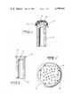
- FIG. 1is a cross-sectional view of the cardiac pacemaker porous electrode tip of the instant invention
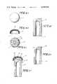
- FIG. 2is a cross-sectional view of the shaft for the electrode tip of FIG. 1;
- FIG. 3is a top view of the cardiac pacemaker electrode tip of FIG. 1;
- FIGS. 4(a)-4(f)illustrate the steps performed in the method for constructing the porous cardiac pacemaker electrode tip of FIG. 1.
- the cardiac pacemaker porous electrode tip of the instant inventioncomprises an electrode cap 11 and an electrode shaft 13.
- the electrode cap 11comprises, for example, a 0.25 mm thick section of platinum sheet or rod which has been formed into a substantially concavo-convex shape having an area in the range of 4 mm 2 to 8 mm 2 and a diameter of approximately 2 mm.
- the convex surface 15comprises the exterior surface of the electrode cap 11 and defines a hollow area or cavity 18 above the end of the electrode shaft 13 and the concave surface 17 comprises the interior surface of the electrode cap 11.
- a plurality of apertures 19is drilled through the electrode cap 11 to communicate with the cavity 18.
- the apertures 19are provided in a uniformly spaced manner.
- the apertures 19are generally frusto-conical shape having an interior diameter of 120 microns in the convex surface 15 and an interior diameter of 100 microns at the concave surface 17.
- These larger apertures 25facilitate fluid ingress and tissue ingrowth in the case of "side on” electrode tip location. It is contemplated, however, that the diameters of the apertures could be varied or that the apertures could be formed in different geometrical shapes. For example the major diameters of the apertures 25 could be in the range of 60 to 1200 microns and the minor diameters could be in the range of 15 to 300 microns.
- one end 27 of the cylindrical member 21has been constructed with a supporting edge 23.
- the other end 29 of the cylindrical member 21interfaces with the electrical conductor used in the pacemaker lead.
- FIG. 3is a top view of the electrode cap 11 and illustrates the location of the apertures in the electrode cap 11.
- the geometric surface area of the electrode cap 11is approximately 8.0 mm 2 . This small area results in an increased pacing impedance.
- the microsurface area of the entire electrode cap 11is approximately 20 mm 2 .
- FIGS. 4(a)-4(f)illustrate an example of the step to be performed during the fabrication of a porous cardiac pacemaker electrode of the instant invention.
- a plate of platinum or other suitable electrode materialis provided.
- the platinum plateis deformed or machined to a substantially concavo-convex shape as illustrated in FIG. 4(b).
- a plurality of apertures 19 and 25are formed in the concavo-convex plate as illustrated in FIG. 4(c). It is contemplated that the aperture-forming step will be performed by drilling with a laser, electron beam device, or other means capable of drilling apertures of predetermined shapes and sizes in an accurately locatable manner.
- the location and number of the apertures 19, 25will be selected according to the desired electrical properties for the electrode and the desired extent of tissue ingrowth.
- an electrode shaft 13is provided with an opening 31 to accommodate an electrode conductor lead (not shown).
- the end of the electrode shaft 13is treated to provide the supporting edge 23 as shown in FIG. 4(e).
- the supporting edge 23is joined to the concave surface 17 of the electrode cap 11 by means of laser welding or other equivalent treatment.
- the external surface 15 of the cap 11then has its microsurface area increased by roughening to form at least one area 33 (FIG. 4(f)) with crevices, irregularities, protuberances, etc. thereon.
- the preferred method of roughening the exterior surface 15 of the cap 11is by glass bead blasting. Nonetheless, methods such as spark erosion (electrical needle etching), could be used.
- a suitable roughening methodis disclosed in U.S. patent application Ser. No. 251,340 filed on even date herewith on behalf of Hirshorn et al. and entitled "Cardiac Pacemaker Electrode Tip Structure And Methods For Making the Same". The disclosure of that application is incorporated herein by reference.
- the above-described methodproduces a porous cardiac pacemaker electrode having a small geometric surface area, and thus, a high pacing impedance to ensure a low current drain on the pacemaker power source.
- the designprovides a large microsurface area enabling a low sensing impedance and improved sensing capability.
- the plurality of apertures through the electrodewhich causes it to be porous, facilitates the attachment of the electrode to the surrounding tissue by enabling the tissue to grow into the apertures and minimize the chronic tissue capsule thickness and consequent threshold.
Landscapes
- Health & Medical Sciences (AREA)
- Heart & Thoracic Surgery (AREA)
- Vascular Medicine (AREA)
- Cardiology (AREA)
- Engineering & Computer Science (AREA)
- Biomedical Technology (AREA)
- Nuclear Medicine, Radiotherapy & Molecular Imaging (AREA)
- Radiology & Medical Imaging (AREA)
- Life Sciences & Earth Sciences (AREA)
- Animal Behavior & Ethology (AREA)
- General Health & Medical Sciences (AREA)
- Public Health (AREA)
- Veterinary Medicine (AREA)
- Electrotherapy Devices (AREA)
Abstract
Description
Claims (12)
Priority Applications (6)
| Application Number | Priority Date | Filing Date | Title |
|---|---|---|---|
| US06/251,708US4408604A (en) | 1981-04-06 | 1981-04-06 | Porous pacemaker electrode tip |
| AU81941/82AAU561332B2 (en) | 1981-04-06 | 1982-03-26 | Porous pacemaker electrode tip |
| GB8209134AGB2096001B (en) | 1981-04-06 | 1982-03-29 | Porous pacemaker electrode tip and method for making the same |
| FR8205875AFR2511251B1 (en) | 1981-04-06 | 1982-04-05 | POROUS ELECTRODE TIP FOR HEART STIMULATOR AND MANUFACTURING METHOD |
| DE3213331ADE3213331C2 (en) | 1981-04-06 | 1982-04-06 | Electrode tip for a pacemaker and process for its manufacture |
| JP57056131AJPS5812661A (en) | 1981-04-06 | 1982-04-06 | Porous electrode for pace-maker and production thereof |
Applications Claiming Priority (1)
| Application Number | Priority Date | Filing Date | Title |
|---|---|---|---|
| US06/251,708US4408604A (en) | 1981-04-06 | 1981-04-06 | Porous pacemaker electrode tip |
Publications (1)
| Publication Number | Publication Date |
|---|---|
| US4408604Atrue US4408604A (en) | 1983-10-11 |
Family
ID=22953071
Family Applications (1)
| Application Number | Title | Priority Date | Filing Date |
|---|---|---|---|
| US06/251,708Expired - LifetimeUS4408604A (en) | 1981-04-06 | 1981-04-06 | Porous pacemaker electrode tip |
Country Status (6)
| Country | Link |
|---|---|
| US (1) | US4408604A (en) |
| JP (1) | JPS5812661A (en) |
| AU (1) | AU561332B2 (en) |
| DE (1) | DE3213331C2 (en) |
| FR (1) | FR2511251B1 (en) |
| GB (1) | GB2096001B (en) |
Cited By (29)
| Publication number | Priority date | Publication date | Assignee | Title |
|---|---|---|---|---|
| US4649937A (en)* | 1985-01-28 | 1987-03-17 | Cordis Corporation | Etched grooved electrode for pacing lead and method for making same |
| US4784161A (en)* | 1986-11-24 | 1988-11-15 | Telectronics, N.V. | Porous pacemaker electrode tip using a porous substrate |
| US4819661A (en)* | 1987-10-26 | 1989-04-11 | Cardiac Pacemakers, Inc. | Positive fixation cardiac electrode with drug elution capabilities |
| US4844099A (en)* | 1986-11-24 | 1989-07-04 | Telectronics, N.V. | Porous pacemaker electrode tip using a porous substrate |
| US5074313A (en)* | 1989-03-20 | 1991-12-24 | Cardiac Pacemakers, Inc. | Porous electrode with enhanced reactive surface |
| US5097843A (en)* | 1990-04-10 | 1992-03-24 | Siemens-Pacesetter, Inc. | Porous electrode for a pacemaker |
| WO1993000130A1 (en)* | 1991-06-20 | 1993-01-07 | Possis Medical, Inc. | Cardiac lead with retractable fixators |
| US5181526A (en)* | 1990-04-20 | 1993-01-26 | Tanaka Kikinzoku Kogyo K.K. | Electrode for human heart pacemaker |
| US5318572A (en)* | 1992-06-02 | 1994-06-07 | Siemens Pacesetter, Inc. | High efficiency tissue stimulating and signal sensing electrode |
| US5326448A (en)* | 1992-10-15 | 1994-07-05 | Telectronics Pacing Systems, Inc. | Method for reducing the polarization of bioelectrical stimulation leads using surface enhancement, and product made thereby |
| US5522875A (en)* | 1994-07-28 | 1996-06-04 | Medtronic, Inc. | Medical electrical lead system having a torque transfer stylet |
| US5522874A (en)* | 1994-07-28 | 1996-06-04 | Gates; James T. | Medical lead having segmented electrode |
| US5571158A (en)* | 1991-08-06 | 1996-11-05 | Biotronik Mess- Und Therapiegeraete Gmbh & Co. Ingenieurbuero Berlin | Stimulation Electrode |
| US5654030A (en)* | 1995-02-07 | 1997-08-05 | Intermedics, Inc. | Method of making implantable stimulation electrodes |
| US6198973B1 (en) | 1999-05-26 | 2001-03-06 | Pacesetter, Inc. | Integrated steroid eluting pacing tip electrode |
| US20070265692A1 (en)* | 2006-05-15 | 2007-11-15 | Cardiac Pacemakers, Inc. | Porous surface electrode for coronary venous applications |
| US20080161887A1 (en)* | 2006-12-28 | 2008-07-03 | Cvrx, Inc. | Noble metal electrodes with nanostructures |
| US20080215125A1 (en)* | 2006-08-07 | 2008-09-04 | Alpha Omega Engineering Ltd. | Directional stimulation of neural tissue |
| US20100137963A1 (en)* | 2005-01-25 | 2010-06-03 | Medtronic, Inc. | Method for fabrication of low-polarization implantable stimulation electrode |
| US20130296678A1 (en)* | 2012-04-24 | 2013-11-07 | Cardiac Pacemakers, Inc. | Combination structural porous surfaces for functional electrode stimulation and sensing |
| US9025598B1 (en) | 2012-03-22 | 2015-05-05 | Nuax, Inc. | Cable/guidewire/interconnects communication apparatus and methods |
| US9193313B2 (en) | 2012-03-22 | 2015-11-24 | Nuax, Inc. | Methods and apparatuses involving flexible cable/guidewire/interconnects |
| US9242100B2 (en) | 2012-08-07 | 2016-01-26 | Nuax, Inc. | Optical fiber-fine wire lead for electrostimulation and sensing |
| US9478327B2 (en) | 2008-05-28 | 2016-10-25 | Nuax, Inc. | Durable fine wire electrical conductor suitable for extreme environment applications |
| US9513443B2 (en) | 2008-05-28 | 2016-12-06 | John Lawrence Erb | Optical fiber-fine wire conductor and connectors |
| US20220409892A1 (en)* | 2019-05-29 | 2022-12-29 | AtaCor Medical, Inc. | Implantable electrical leads and associated delivery systems |
| US11844949B2 (en) | 2014-09-04 | 2023-12-19 | AtaCor Medical, Inc. | Cardiac defibrillation |
| US11931586B2 (en) | 2014-11-24 | 2024-03-19 | AtaCor Medical, Inc. | Cardiac pacing sensing and control |
| US11937987B2 (en) | 2014-09-04 | 2024-03-26 | AtaCor Medical, Inc. | Cardiac arrhythmia treatment devices and delivery |
Families Citing this family (12)
| Publication number | Priority date | Publication date | Assignee | Title |
|---|---|---|---|---|
| JPS59105460A (en)* | 1982-12-08 | 1984-06-18 | 田中貴金属工業株式会社 | Platinum electrode body for pace maker |
| DE3300672A1 (en)* | 1983-01-11 | 1984-07-12 | Siemens AG, 1000 Berlin und 8000 München | HEART PACEMAKER SYSTEM |
| DE3305271A1 (en)* | 1983-02-16 | 1984-08-16 | Siemens AG, 1000 Berlin und 8000 München | ELECTRODE ARRANGEMENT |
| JPS60261467A (en)* | 1984-06-11 | 1985-12-24 | 田中貴金属工業株式会社 | Manufacturing method for pacemaker electrodes |
| DE4324185A1 (en)* | 1993-07-19 | 1995-01-26 | Siemens Ag | Electrode for electromedical applications |
| US5683443A (en)* | 1995-02-07 | 1997-11-04 | Intermedics, Inc. | Implantable stimulation electrodes with non-native metal oxide coating mixtures |
| DE19545090A1 (en)* | 1995-12-04 | 1997-06-05 | Hartung Dagmar Dipl Med | Arrangement for stimulating irritable body tissue |
| RU2120231C1 (en)* | 1996-06-11 | 1998-10-20 | Государственное предприятие конструкторское бюро "СПЕЦВУЗАВТОМАТИКА" | Electrode device |
| US5991667A (en)* | 1997-11-10 | 1999-11-23 | Vitatron Medical, B.V. | Pacing lead with porous electrode for stable low threshold high impedance pacing |
| FR2777465B1 (en) | 1998-04-15 | 2000-06-09 | Ela Medical Sa | INCREASED IMPEDANCE PROBE FOR IMPLANTED MEDICAL DEVICE, PARTICULARLY FOR HEART STIMULATOR |
| RU2257235C1 (en)* | 2004-02-02 | 2005-07-27 | Карасев Александр Александрович | Electrode device |
| AU2016271986A1 (en)* | 2015-05-29 | 2017-12-07 | University Of Waikato | A surgical implant conductor with increased radio frequency alternating current resistance |
Citations (8)
| Publication number | Priority date | Publication date | Assignee | Title |
|---|---|---|---|---|
| US3754555A (en)* | 1971-10-05 | 1973-08-28 | G Schmitt | Controllable barbed intracardial electrode |
| US3911928A (en)* | 1973-04-14 | 1975-10-14 | Hans Lagergren | Endocardial electrode |
| US3935864A (en)* | 1973-07-04 | 1976-02-03 | Hans Lagergren | Endocardial electrode |
| US3981309A (en)* | 1974-12-23 | 1976-09-21 | American Optical Corporation | Patient stimulating pacer electrode |
| US4011861A (en)* | 1974-04-03 | 1977-03-15 | Case Western Reserve University | Implantable electric terminal for organic tissue |
| US4030508A (en)* | 1976-02-04 | 1977-06-21 | Vitatron Medical B.V. | Low output electrode for cardiac pacing |
| US4052754A (en)* | 1975-08-14 | 1977-10-11 | Homsy Charles A | Implantable structure |
| US4280514A (en)* | 1975-05-09 | 1981-07-28 | Macgregor David C | Endocardial pacemaker electrode |
Family Cites Families (12)
| Publication number | Priority date | Publication date | Assignee | Title |
|---|---|---|---|---|
| CA961116A (en)* | 1970-10-19 | 1975-01-14 | Heinrich Schmidt | Method and apparatus for perforating foils and thin metal sheets, especially for fine, slot-shaped openings |
| CH547631A (en)* | 1972-02-02 | 1974-04-11 | Sulzer Ag | SHAFT FOR BONE IMPLANTS. |
| FR2215927B1 (en)* | 1973-01-31 | 1976-05-14 | Louyot Comptoir Lyon Alemand | |
| JPS5091985A (en)* | 1973-12-19 | 1975-07-23 | ||
| JPS51790A (en)* | 1974-06-25 | 1976-01-06 | Seiko Instr & Electronics | JINKOSHINZOPEESUMEEKAAYODENKYOKU |
| AU509186B2 (en)* | 1975-08-14 | 1980-04-24 | Vitek Inc. | Surgical implant |
| FR2378529A1 (en)* | 1975-10-28 | 1978-08-25 | Univ Case Western Reserve | Implantable electrical terminal for organic tissue - is porous to intermesh with tissue without formation of fibrous tissue encapsulation |
| DE2613072C3 (en)* | 1976-03-26 | 1987-07-30 | Siemens AG, 1000 Berlin und 8000 München | Implantable electrode |
| US4156429A (en)* | 1977-10-11 | 1979-05-29 | Cardiac Pacemakers, Inc. | Implantable electrode |
| FR2446001A1 (en)* | 1979-01-03 | 1980-08-01 | Cardiofrance Co | Electrical conductor for cardiac pacemaker - has inner conducting sleeve surrounded by carbon fibres inside outer flexible insulating sleeve |
| JPS55110564A (en)* | 1979-02-13 | 1980-08-26 | Cardiac Pacemakers Inc | Electrode device that can be buried under skin |
| JPS57193852U (en)* | 1981-05-04 | 1982-12-08 |
- 1981
- 1981-04-06USUS06/251,708patent/US4408604A/ennot_activeExpired - Lifetime
- 1982
- 1982-03-26AUAU81941/82Apatent/AU561332B2/ennot_activeCeased
- 1982-03-29GBGB8209134Apatent/GB2096001B/ennot_activeExpired
- 1982-04-05FRFR8205875Apatent/FR2511251B1/ennot_activeExpired
- 1982-04-06DEDE3213331Apatent/DE3213331C2/ennot_activeExpired - Fee Related
- 1982-04-06JPJP57056131Apatent/JPS5812661A/enactiveGranted
Patent Citations (11)
| Publication number | Priority date | Publication date | Assignee | Title |
|---|---|---|---|---|
| US3754555A (en)* | 1971-10-05 | 1973-08-28 | G Schmitt | Controllable barbed intracardial electrode |
| US3911928A (en)* | 1973-04-14 | 1975-10-14 | Hans Lagergren | Endocardial electrode |
| US3911928B1 (en)* | 1973-04-14 | 1988-11-08 | ||
| US3935864A (en)* | 1973-07-04 | 1976-02-03 | Hans Lagergren | Endocardial electrode |
| GB1471488A (en) | 1973-07-04 | 1977-04-27 | Lagergren H | Endocardiac electrode devices |
| US3935864B1 (en)* | 1973-07-04 | 1988-11-08 | Endocardial electrode | |
| US4011861A (en)* | 1974-04-03 | 1977-03-15 | Case Western Reserve University | Implantable electric terminal for organic tissue |
| US3981309A (en)* | 1974-12-23 | 1976-09-21 | American Optical Corporation | Patient stimulating pacer electrode |
| US4280514A (en)* | 1975-05-09 | 1981-07-28 | Macgregor David C | Endocardial pacemaker electrode |
| US4052754A (en)* | 1975-08-14 | 1977-10-11 | Homsy Charles A | Implantable structure |
| US4030508A (en)* | 1976-02-04 | 1977-06-21 | Vitatron Medical B.V. | Low output electrode for cardiac pacing |
Non-Patent Citations (6)
| Title |
|---|
| Amundson et al., "The Porous Endocardial Electrode," PACE, vol. 2, Jan.-Feb. 1979, pp. 40-50.* |
| Amundson, "Characteristics of the CPI Porous Tip Electrode," Impulse, Apr. 1979, pp. 7-10, 14.* |
| Barold et al., "Cardiovascular Instrumentation," Chest, 70, Dec. 6, 1976, pp. 760-766.* |
| Hirshorn et al., "Histological Evaluation of Porous Titanium Cardiac Pacemaker Electrode Tips," First Asian-Pacific Symposium on Cardiac Pacing, Jun. 16, 1980, P2.37.* |
| MacGregor et al., "The Porous-Surfaced Electrode," The Journal of Thoracic and Cardiovascular Surgery, vol. 38, No. 2, Aug. 1979 pp. 280-291.* |
| Munde et al., "Development of a Non-Polarizable Stimulating Electrode for Implantable Cardiac Pacemakers," Siemens Prosche u Entwicki-Ber BD 8 (1979) Nr4, pp. 227-234.* |
Cited By (41)
| Publication number | Priority date | Publication date | Assignee | Title |
|---|---|---|---|---|
| US4649937A (en)* | 1985-01-28 | 1987-03-17 | Cordis Corporation | Etched grooved electrode for pacing lead and method for making same |
| US4784161A (en)* | 1986-11-24 | 1988-11-15 | Telectronics, N.V. | Porous pacemaker electrode tip using a porous substrate |
| US4844099A (en)* | 1986-11-24 | 1989-07-04 | Telectronics, N.V. | Porous pacemaker electrode tip using a porous substrate |
| US4819661A (en)* | 1987-10-26 | 1989-04-11 | Cardiac Pacemakers, Inc. | Positive fixation cardiac electrode with drug elution capabilities |
| US5074313A (en)* | 1989-03-20 | 1991-12-24 | Cardiac Pacemakers, Inc. | Porous electrode with enhanced reactive surface |
| US5097843A (en)* | 1990-04-10 | 1992-03-24 | Siemens-Pacesetter, Inc. | Porous electrode for a pacemaker |
| US5330700A (en)* | 1990-04-10 | 1994-07-19 | Siemens Pacesetter, Inc. | Porous electrode for a pacemaker and method of making same |
| US5181526A (en)* | 1990-04-20 | 1993-01-26 | Tanaka Kikinzoku Kogyo K.K. | Electrode for human heart pacemaker |
| US5179962A (en)* | 1991-06-20 | 1993-01-19 | Possis Medical, Inc. | Cardiac lead with retractible fixators |
| WO1993000130A1 (en)* | 1991-06-20 | 1993-01-07 | Possis Medical, Inc. | Cardiac lead with retractable fixators |
| US5571158A (en)* | 1991-08-06 | 1996-11-05 | Biotronik Mess- Und Therapiegeraete Gmbh & Co. Ingenieurbuero Berlin | Stimulation Electrode |
| US5318572A (en)* | 1992-06-02 | 1994-06-07 | Siemens Pacesetter, Inc. | High efficiency tissue stimulating and signal sensing electrode |
| US5326448A (en)* | 1992-10-15 | 1994-07-05 | Telectronics Pacing Systems, Inc. | Method for reducing the polarization of bioelectrical stimulation leads using surface enhancement, and product made thereby |
| US5522875A (en)* | 1994-07-28 | 1996-06-04 | Medtronic, Inc. | Medical electrical lead system having a torque transfer stylet |
| US5522874A (en)* | 1994-07-28 | 1996-06-04 | Gates; James T. | Medical lead having segmented electrode |
| US5654030A (en)* | 1995-02-07 | 1997-08-05 | Intermedics, Inc. | Method of making implantable stimulation electrodes |
| US6198973B1 (en) | 1999-05-26 | 2001-03-06 | Pacesetter, Inc. | Integrated steroid eluting pacing tip electrode |
| US20100137963A1 (en)* | 2005-01-25 | 2010-06-03 | Medtronic, Inc. | Method for fabrication of low-polarization implantable stimulation electrode |
| US20070265692A1 (en)* | 2006-05-15 | 2007-11-15 | Cardiac Pacemakers, Inc. | Porous surface electrode for coronary venous applications |
| US20080215125A1 (en)* | 2006-08-07 | 2008-09-04 | Alpha Omega Engineering Ltd. | Directional stimulation of neural tissue |
| US7917231B2 (en)* | 2006-08-07 | 2011-03-29 | Alpha Omega Neuro Technologies Ltd. | Directional stimulation of neural tissue |
| US20080161887A1 (en)* | 2006-12-28 | 2008-07-03 | Cvrx, Inc. | Noble metal electrodes with nanostructures |
| US9513443B2 (en) | 2008-05-28 | 2016-12-06 | John Lawrence Erb | Optical fiber-fine wire conductor and connectors |
| US9478327B2 (en) | 2008-05-28 | 2016-10-25 | Nuax, Inc. | Durable fine wire electrical conductor suitable for extreme environment applications |
| US9025598B1 (en) | 2012-03-22 | 2015-05-05 | Nuax, Inc. | Cable/guidewire/interconnects communication apparatus and methods |
| US9193313B2 (en) | 2012-03-22 | 2015-11-24 | Nuax, Inc. | Methods and apparatuses involving flexible cable/guidewire/interconnects |
| US20130296678A1 (en)* | 2012-04-24 | 2013-11-07 | Cardiac Pacemakers, Inc. | Combination structural porous surfaces for functional electrode stimulation and sensing |
| US9242100B2 (en) | 2012-08-07 | 2016-01-26 | Nuax, Inc. | Optical fiber-fine wire lead for electrostimulation and sensing |
| US11937987B2 (en) | 2014-09-04 | 2024-03-26 | AtaCor Medical, Inc. | Cardiac arrhythmia treatment devices and delivery |
| US12296176B2 (en) | 2014-09-04 | 2025-05-13 | AtaCor Medical, Inc. | Cardiac defibrillation |
| US11844949B2 (en) | 2014-09-04 | 2023-12-19 | AtaCor Medical, Inc. | Cardiac defibrillation |
| US12128239B2 (en) | 2014-11-24 | 2024-10-29 | AtaCor Medical, Inc. | Cardiac pacing sensing and control |
| US11931586B2 (en) | 2014-11-24 | 2024-03-19 | AtaCor Medical, Inc. | Cardiac pacing sensing and control |
| US12226641B2 (en) | 2014-11-24 | 2025-02-18 | AtaCor Medical, Inc. | Cardiac pacing sensing and control |
| US12296175B2 (en) | 2014-11-24 | 2025-05-13 | AtaCor Medical, Inc. | Cardiac pacing sensing and control |
| US12303696B2 (en) | 2014-11-24 | 2025-05-20 | AtaCor Medical, Inc. | Cardiac pacing sensing and control |
| US12303698B2 (en) | 2014-11-24 | 2025-05-20 | AtaCor Medical, Inc. | Cardiac pacing sensing and control |
| US12350499B2 (en) | 2014-11-24 | 2025-07-08 | AtaCor Medical, Inc. | Cardiac pacing sensing and control |
| US11998736B2 (en)* | 2019-05-29 | 2024-06-04 | AtaCor Medical, Inc. | Implantable electrical leads and associated delivery systems |
| US12208260B2 (en) | 2019-05-29 | 2025-01-28 | Kurin, Inc. | Implantable electrical leads and electrodes |
| US20220409892A1 (en)* | 2019-05-29 | 2022-12-29 | AtaCor Medical, Inc. | Implantable electrical leads and associated delivery systems |
Also Published As
| Publication number | Publication date |
|---|---|
| GB2096001A (en) | 1982-10-13 |
| FR2511251B1 (en) | 1986-10-10 |
| AU8194182A (en) | 1983-10-13 |
| DE3213331A1 (en) | 1982-11-11 |
| JPH0235582B2 (en) | 1990-08-10 |
| GB2096001B (en) | 1985-07-03 |
| JPS5812661A (en) | 1983-01-24 |
| AU561332B2 (en) | 1987-05-07 |
| DE3213331C2 (en) | 1995-10-19 |
| FR2511251A1 (en) | 1983-02-18 |
Similar Documents
| Publication | Publication Date | Title |
|---|---|---|
| US4408604A (en) | Porous pacemaker electrode tip | |
| US5318572A (en) | High efficiency tissue stimulating and signal sensing electrode | |
| US4784161A (en) | Porous pacemaker electrode tip using a porous substrate | |
| US4844099A (en) | Porous pacemaker electrode tip using a porous substrate | |
| US8755910B2 (en) | Reference electrodes for inner ear stimulation devices | |
| US4030508A (en) | Low output electrode for cardiac pacing | |
| US5085218A (en) | Bipolar myocardial positive fixation lead with improved sensing capability | |
| US6263250B1 (en) | Ring electrode with porous member | |
| US5871529A (en) | Electrode for high impedance heart stimulation | |
| US5423865A (en) | Electrode system for a defibrillator | |
| EP0622090B1 (en) | Sintered electrode on a substrate | |
| US20090088827A1 (en) | Lead assembly providing sensing or stimulation of spaced-apart myocardial contact areas | |
| JPH09509872A (en) | Cardiac pacemaker with coating | |
| JP2008521579A (en) | Subcutaneous implantable cardiac pacemaker | |
| US20090204194A1 (en) | Medical system including a novel bipolar pacing pair | |
| JPH06190061A (en) | Electrode device for pacemaker | |
| US4407302A (en) | Cardiac pacemaker electrode tip structure | |
| WO2008031144A1 (en) | Implantable electrode array | |
| EP1666086B1 (en) | Automatic capture pacing lead | |
| US7058454B1 (en) | Stimulation/sensing electrodes for use with implantable cardiac leads in coronary vein locations | |
| WO1994000088A1 (en) | Curved electrode array | |
| CN215195029U (en) | Artificial cochlea implanting device and artificial cochlea | |
| EP4101495A1 (en) | Ring electrode with a special contacting channel | |
| CN116847903A (en) | Medical implant electrode with controlled porosity | |
| WO2024170982A1 (en) | Distal end fixation for implantable medical device |
Legal Events
| Date | Code | Title | Description |
|---|---|---|---|
| AS | Assignment | Owner name:TELECTRONICS PTY., LIMITED, 2 SIRIUS RD. LANE COVE Free format text:ASSIGNMENT OF ASSIGNORS INTEREST.;ASSIGNORS:HIRSHORN MICHAEL S.;SKALSKY MICHAEL;VAN BERKUM PETROS A.;AND OTHERS;REEL/FRAME:003876/0801 Effective date:19810330 | |
| STCF | Information on status: patent grant | Free format text:PATENTED CASE | |
| MAFP | Maintenance fee payment | Free format text:PAYMENT OF MAINTENANCE FEE, 4TH YEAR, PL 96-517 (ORIGINAL EVENT CODE: M170); ENTITY STATUS OF PATENT OWNER: LARGE ENTITY Year of fee payment:4 | |
| FEPP | Fee payment procedure | Free format text:PAYOR NUMBER ASSIGNED (ORIGINAL EVENT CODE: ASPN); ENTITY STATUS OF PATENT OWNER: LARGE ENTITY | |
| MAFP | Maintenance fee payment | Free format text:PAYMENT OF MAINTENANCE FEE, 8TH YEAR, PL 96-517 (ORIGINAL EVENT CODE: M171); ENTITY STATUS OF PATENT OWNER: LARGE ENTITY Year of fee payment:8 | |
| FEPP | Fee payment procedure | Free format text:PAYOR NUMBER ASSIGNED (ORIGINAL EVENT CODE: ASPN); ENTITY STATUS OF PATENT OWNER: LARGE ENTITY Free format text:PAYER NUMBER DE-ASSIGNED (ORIGINAL EVENT CODE: RMPN); ENTITY STATUS OF PATENT OWNER: LARGE ENTITY | |
| AS | Assignment | Owner name:TELECTRONICS PACING SYSTEMS, INC., COLORADO Free format text:ASSIGNORS HEREBY CONFIRMS THE ENTIRE INTEREST IN SAID INVENTIONS TO ASSIGNEE ELECUTED ON SEPT. 16, 1988;ASSIGNORS:TELECTRONICS PTY. LTD.;MEDICAL TELECTRONICS HOLDING & FINANCE CO.;TELECTRONIC NV;AND OTHERS;REEL/FRAME:006172/0028 Effective date:19920622 | |
| MAFP | Maintenance fee payment | Free format text:PAYMENT OF MAINTENANCE FEE, 12TH YEAR, LARGE ENTITY (ORIGINAL EVENT CODE: M185); ENTITY STATUS OF PATENT OWNER: LARGE ENTITY Year of fee payment:12 | |
| AS | Assignment | Owner name:TELECTRONICS PACING SYSTEMS, INC., COLORADO Free format text:CORRECTIVE ASSIGNMENT TO CORRECT ASSIGNEE'S STATE OF INCORPORATION. AN ASSIGNMENT WAS PREVIOUSLY RECORDED AT REEL 6172, FRAME 0028;ASSIGNORS:TELECTRONICS PTY. LTD., AN AUSTRALIAN COMPANY;MEDICAL TELECTRONICS HOLDING & FINANCE CO. (BV), A DUTCH COMPANY;TELECTRONICS NV, A COMPANY OF THE NETHERLANDS ANTILLES;AND OTHERS;REEL/FRAME:008321/0072 Effective date:19961101 | |
| AS | Assignment | Owner name:PACESETTER, INC., CALIFORNIA Free format text:ASSIGNMENT OF ASSIGNORS INTEREST;ASSIGNOR:TELECTRONICS PACING SYSTEMS;REEL/FRAME:008454/0461 Effective date:19961129 |