US4407000A - Combined dipole and ferrite antenna - Google Patents
Combined dipole and ferrite antennaDownload PDFInfo
- Publication number
- US4407000A US4407000AUS06/277,100US27710081AUS4407000AUS 4407000 AUS4407000 AUS 4407000AUS 27710081 AUS27710081 AUS 27710081AUS 4407000 AUS4407000 AUS 4407000A
- Authority
- US
- United States
- Prior art keywords
- bobbin
- antenna
- length
- wings
- coil
- Prior art date
- Legal status (The legal status is an assumption and is not a legal conclusion. Google has not performed a legal analysis and makes no representation as to the accuracy of the status listed.)
- Expired - Fee Related
Links
- 229910000859α-FeInorganic materials0.000titleclaimsabstractdescription60
- 239000004020conductorSubstances0.000claimsabstractdescription23
- 239000003990capacitorSubstances0.000claimsabstractdescription15
- 230000008878couplingEffects0.000claimsdescription8
- 238000010168coupling processMethods0.000claimsdescription8
- 238000005859coupling reactionMethods0.000claimsdescription8
- 230000003247decreasing effectEffects0.000description3
- 230000005540biological transmissionEffects0.000description2
- 238000010586diagramMethods0.000description2
- 230000000694effectsEffects0.000description2
- 239000003989dielectric materialSubstances0.000description1
Images


Classifications
- H—ELECTRICITY
- H01—ELECTRIC ELEMENTS
- H01Q—ANTENNAS, i.e. RADIO AERIALS
- H01Q9/00—Electrically-short antennas having dimensions not more than twice the operating wavelength and consisting of conductive active radiating elements
- H01Q9/04—Resonant antennas
- H01Q9/16—Resonant antennas with feed intermediate between the extremities of the antenna, e.g. centre-fed dipole
- H—ELECTRICITY
- H01—ELECTRIC ELEMENTS
- H01Q—ANTENNAS, i.e. RADIO AERIALS
- H01Q1/00—Details of, or arrangements associated with, antennas
- H01Q1/36—Structural form of radiating elements, e.g. cone, spiral, umbrella; Particular materials used therewith
- H—ELECTRICITY
- H01—ELECTRIC ELEMENTS
- H01Q—ANTENNAS, i.e. RADIO AERIALS
- H01Q21/00—Antenna arrays or systems
- H01Q21/29—Combinations of different interacting antenna units for giving a desired directional characteristic
- H—ELECTRICITY
- H01—ELECTRIC ELEMENTS
- H01Q—ANTENNAS, i.e. RADIO AERIALS
- H01Q3/00—Arrangements for changing or varying the orientation or the shape of the directional pattern of the waves radiated from an antenna or antenna system
- H01Q3/02—Arrangements for changing or varying the orientation or the shape of the directional pattern of the waves radiated from an antenna or antenna system using mechanical movement of antenna or antenna system as a whole
- H—ELECTRICITY
- H01—ELECTRIC ELEMENTS
- H01Q—ANTENNAS, i.e. RADIO AERIALS
- H01Q7/00—Loop antennas with a substantially uniform current distribution around the loop and having a directional radiation pattern in a plane perpendicular to the plane of the loop
- H01Q7/005—Loop antennas with a substantially uniform current distribution around the loop and having a directional radiation pattern in a plane perpendicular to the plane of the loop with variable reactance for tuning the antenna
- H—ELECTRICITY
- H01—ELECTRIC ELEMENTS
- H01Q—ANTENNAS, i.e. RADIO AERIALS
- H01Q7/00—Loop antennas with a substantially uniform current distribution around the loop and having a directional radiation pattern in a plane perpendicular to the plane of the loop
- H01Q7/06—Loop antennas with a substantially uniform current distribution around the loop and having a directional radiation pattern in a plane perpendicular to the plane of the loop with core of ferromagnetic material
- H01Q7/08—Ferrite rod or like elongated core
- H—ELECTRICITY
- H01—ELECTRIC ELEMENTS
- H01Q—ANTENNAS, i.e. RADIO AERIALS
- H01Q9/00—Electrically-short antennas having dimensions not more than twice the operating wavelength and consisting of conductive active radiating elements
- H01Q9/04—Resonant antennas
- H—ELECTRICITY
- H01—ELECTRIC ELEMENTS
- H01Q—ANTENNAS, i.e. RADIO AERIALS
- H01Q9/00—Electrically-short antennas having dimensions not more than twice the operating wavelength and consisting of conductive active radiating elements
- H01Q9/04—Resonant antennas
- H01Q9/06—Details
- H01Q9/14—Length of element or elements adjustable
- H01Q9/145—Length of element or elements adjustable by varying the electrical length
Definitions
- the present inventionrelates to an improved structure of an antenna, in particular, relates to a room antenna having high enough gain and being small enough in size to be suitable for the reception of VHF and/or UHF band.
- the present antennais in particular utilized for the reception of an FM broadcasting in 76-90 MHz in Japan.
- FIG. 1AOne of the prior antennas of this kind is shown in FIG. 1A, which is called a ferrite antenna, having a vertical ferrite bar 1.
- the reference numeral 2is a tank circuit having a coil 3 wound around the bar 1 and the variable capacitor 4, and 5 is an output coil wound around the ferrite bar 1.
- a ferrite antennahas been widely used since it provides high output voltage due to the high permiability of a ferrite bar.
- the variable capacitor 4provides the resonant condition of the tank circuit 2 by adjusting the capacitor 4, so that the resonant frequency of the tank circuit becomes equal to the desired reception frequency.
- the antenna outputis provided from the output coil 5 through the output terminal 6.
- the gain G of the ferrite antenna of FIG. 1Ais shown below:
- the gain G of the antennais proportional to the values ⁇ e , Q e , S and L f .
- FIG. 1Bshows the relationships between the gain G of the ferrite antenna, and the length L f and the diameter ⁇ of the ferrite antenna of FIG. 1A, where the values ⁇ e and Q e are given.
- the vertical axisshows the gain G
- the horizontal axisshows the length L f
- ⁇is the parameter.
- the gain G of a ferrite antennais decreased because of the loss by the ferrite core, and further, due to the self inductance and the stray capacitance of the antenna itself, the antenna resonates itself in VHF band. Further, since a ferrite antenna is non-directional in the horizontal plane, when the electromagnetic wave is reflected by buildings and/or other reflectors, the antenna receives an echo due to the multipath by the reflection.
- Another prior antenna for VHF and/or UHF bandis a half wavelength dipole antenna.
- a conventional dipole antennahas the disadvantage that the size is large as the length of a dipole antenna must be 1/2 of the wavelength.
- an antennacomprising a housing; a horizontal first antenna portion having a pair of substantially rectangular wings extending from the top of said housing in the opposite direction from each other; each of said wings having a folded elongated conductor with a plurality of first arms with the length D in the parallel direction of said wings, and a plurality of second arms with the length H in the perpendicular direction to said first arms; extreme ends of said folded elongated conductors in said wings being left free; an elongated ferrite pole positioned vertically in said housing; said ferrite pole having a coupling coil, a tank coil, and an output coil, said coupling coil being coupled with the inner ends of said folded elongated conductors in said pair of wings; said tank coil being coupled with an adjustable capacitor forming a resonator circuit; said output coil being coupled with output terminals; and means for sliding said output coil along said ferrite pole for adjusting output impedance of the present reception antenna.
- said first antenna portion with a pair of wingshas the total horizontal length L in the range from 350 mm to 700 mm.
- the length D of said first armbeing in the range from 6 mm to 12 mm
- the length H of said second armbeing in the range from 40 mm to 150 mm.
- said ferrite polebeing a circular post with the diameter in the range from 10 mm to 30 mm, and the length in the range from 50 mm to 150 mm.
- FIG. 1Ais a structure of a prior ferrite antenna
- FIG. 1Bshows the relations between the gain of the ferrite antenna and the size of the antenna
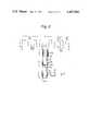
- FIG. 2shows the principle of the present antenna
- FIG. 3is another embodiment of the present antenna
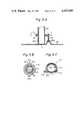
- FIG. 4Ashows the plan view of the antenna of FIG. 2,
- FIG. 4Bis the cross sectional view at the line A--A of FIG. 4A.
- FIG. 5A, FIG. 5B and FIG. 5Cshow the detailed structure of the lower portion of the antenna of FIGS. 4A and 4B,
- FIGS. 6A, 6B and 6Cshow the alternative of the detailed structure of the lower portion of the antenna of FIGS. 4A and 4B,
- FIG. 7shows the relationship between the output impedance of the present antenna and the frequency
- FIG. 8shows the relationship of the gain and the size of a ferrite rod of the antenna of FIG. 2,
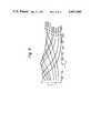
- FIG. 9A and FIG. 9Bshow curves of the gain with the parameter of folded horizontal portion
- FIG. 10shows the curves of the gain of the present antenna, as compared with the gain of prior antennas.
- FIG. 11shows the directivity characteristics of the present antenna.
- FIG. 2 and FIG. 3show the circuit diagrams of the present antenna
- FIGS. 4A and 4Bshow the structure of the antenna of FIG. 2, wherein FIG. 4A is the plan view, and FIG. 4B is the cross sectional view at the line A--A of FIG. 4A.
- the present reception antennahas an elongated first antenna portion 10 which extends horizontally, and a ferrite pole 13 which is positioned vertically.
- a coil 12is provided at the upper portion of the ferrite pole 13, and the combination of the ferrite pole 13 and the coil 12 wound thereon together with a tank circuit 14 and an output coil 15 compose a second antenna portion.
- the first antenna portion 10has an elongated conductor member which is folded or curved repetitively as shown in the figure. In the embodiment of FIG.
- the folded conductoris positioned in the vertical plane.
- the horizontal component of the folded conductor in the elongated direction of the first portion 10is called the first arm 51a, and the component of the folded conductor perpendicular to said first arm 51a is called the second arm 51b, respectively.
- the extreme end 11 of the folded conductoris free or open as shown in the figure.
- Said horizontal folded conductoris separated to the two portions or wings 10a and 10b (see FIG. 4A).
- the ends 12a and 12b of the coil 12are connected to the corresponding inner ends of the half portions or wings 10a and 10b, respectively.
- Another coil 14ais wound on the middle portion of the ferrite pole 13, and said coil 14a is coupled to a variable capacitor 14b.
- the combination of the coil 14a and the capacitor 14bcomposes a resonation circuit or a tank circuit.
- Still another coil 15is wound at the lower portion of the ferrite pole 13, and said coil 15 is coupled with the output terminals 17 of the present antenna, through the baloon transformer 16 which converts the line impedance. That baloon transformer is not shown in FIGS. 4A and 4B.
- the coil 15is called as an output coil.
- FIG. 3shows another circuit diagram of the present reception antenna.
- the feature of the antenna of FIG. 3is that the first antenna portion 10 is positioned on a horizontal plane, while that first antenna portion 10 of FIG. 2 is positioned on a vertical plane.
- the gain of the antenna of FIG. 3is almost the same as that of FIG. 2.
- the antennahas a housing 20 which has the top cover 21, the bottom cover 22, and the side walls 23a and 23b.
- a circular disk 24is engaged with the top cover 21, so that said disk 24 is rotatable around the axis of the disk 24 itself.
- the first upper bobbin 25which is made of dielectric material is fixed beneath said disk 24.
- the coupling coil 12is wound around said first upper bobbin 25.
- the first antenna portion 10has the left wing 10a and the right wing 10b, each comprises of a thin rectangular dielectric plate 50.
- the plate 50has a small projection 50a or 50b at one end of the same, and is fixed on the disk 24 by said projection 50a or 50b.
- a folded conductor wireis inserted in the dielectric plate 50 as shown by the dotted line in the figures.
- the folded wirehas the predetermined period, with the horizontal arm 51a with the length D and the vertical arm 51b with the length H.
- One end of the conductive wire of each wingis electrically coupled with the related end of the coil 12 through the disk 24, and the other end 11 of the wire is left free.
- the first antenna portion 10 together with the first upper bobbin and the coil 12are rotatable around the axis of the bobbin 25.
- the first antenna portionis positioned in the direction of the electromagnetic wave to be received by rotating the same.
- the second lower dielectric bobbin 26is fixed on the bottom cover 22 of the housing 20, so that said first and second bobbins 25 and 26 are aligned on a common axis. A short air gap is left between the two bobbins 25 and 26. A ferrite pole 13 is inserted in both the first bobbin 25 and the second bobbin 26, and the bottom of the ferrite pole 13 is adhered to the bottom cover 22.
- a tank coil 14ais wound on the second bobbin 26, and said tank coil 14a is coupled with the variable capacitor 14b through lead lines.
- Said variable capacitor 14bis fixed to the vertical plate 30 which stands on the bottom cover 22.
- the variable capacitor 14bis adjustable by rotating the knob 40, which is positioned outside of the housing 10. It should be appreciated that the coil 14a and the capacitor 14b compose a tank circuit or a resonator, which resonates with the reception frequency.
- a third bobbin 27is provided so that said third bobbin 27 is capable of being slid on the second bobbin 26.
- An output coil 15is wound on said third bobbin 27, and said output coil 15 is coupled to the output terminals 17 on the side wall of the housing 10.
- a balun transformeris mounted in the housing 10
- said transformeris inserted electrically between the output terminal 17 and the output coil 15.
- that transformeris installed outside of the antenna housing.
- One end of the third bobbin 27is engaged with the screw 28, which is also engaged with the projection 29 on the bottom plate 22. By rotating the screw 28 with a screw driver, the third bobbin 27 is finely postioned on the second bobbin 26.
- the positioning of the third bobbin 27 and the output coil 15define the output impedance of the antenna.
- the bobbins 25 and 26have a circular slit on the outer wall for accepting the wire of the coils 14a, and 15, respectively, and the coils are positioned in those slits.
- FIGS. 5A, 5B and 5Cshow the detailed structure of the third bobbon 27 in the embodiment of FIGS. 4A and 4B.
- the second bobbin 26has a vertical slit 26a on the outside wall of the bobbin 26, and the third bobbin 27 has the internal projection 27d so that said projection 27d is engaged with said vertical linear slit 26a.
- the engagement of the projection 27d with the slit 26aprevents the undesirable rotation of the third bobbin 27 and/or the output coil 15.
- the third bobbin 27has a circular slit in which the output coil 15 is mounted, and the lead lines of said output coil 15 is coupled with the output terminals 17 through a pair of adjacent slits 27e.
- the third bobbin 27has also an external projection 27b which has a female screwed hole 27c.
- the hole 27chas a female screw which is engaged with the screw 28, which positiones the third bobbin 27. After the third bobbin 27 is positioned, the screw 28 is locked by a lock nut 28a.
- FIGS. 6A, 6B and 6Cshow the other embodiment of the third bobbin 27.
- the feature of this embodimentis that no second bobbin is provided and the third bobbin is mounted directly on the ferrite pole 13. In this case, a vertical linear slit may be provided on the ferrite pole 13.
- FIG. 7shows the relationship between the reception frequency (horizontal axis) and the output impedance (VSWR; voltage standing wave ratio) of the antenna.
- the parameters (a), (b) and (c)show the position of the third bobbin 27 (see for instance FIG. 6B).
- the antennais positioned so that the ferrite pole 13 is vertical, or the first antenna portion 10 is horizontal. Then, the horizontal first antenna portion 10 is rotated so that the wings 10a and 10b extend perpendicular to the path of the electromagnetic wave in order to obtain the maximum gain of the antenna. Then, the variable capacitor is adjusted so that the tank circuit resonates with the reception frequency. Then, the positioning of the third bobbin or the output coil is performed so that the output impedance provides the minimum VSWR. The above three operations can be performed so that the reception level becomes maximum. In our experiment, the position of the output coil does not effect much to the gain of the antenna. Therefore, that position of the output coil might be fixed after that output coil is adjusted to a proper location for a middle frequency in the reception frequency band.
- the size of a ferrite poleis small, both the gain and the output impedance are decreased, and when the size of a ferrite pole is large, the output impedance is increased and the gain is then decreased due to the mismatching of the impedance.
- FIG. 8shows the relations between the length L f of a ferrite pole and the gain G of the antenna of FIG. 2, with the parameter of the diameter ⁇ of the ferrite pole, where the horizontal axis shows the length L f in mm and the vertical axis shows the gain G, and the test frequency is 83 MHz.
- the diameter ⁇is in the range from 8 mm to 30 mm
- the length L fis in the range from 50 mm to 200 mm. In the above range, the maximum gain is obtained when the diameter is approximately 20 mm, and the length L f is approximately 75 mm.
- the measured output impedance of a ferrite antennais in the range from 100 ohms to 200 ohms, and the output impedance of the horizontal first antenna portion is in the range from 30 ohms to 150 ohms.
- the measured output impedance of the second ferrite antenna portionis 150 ohms, and the measured output impedance of the first horizontal antenna portion is 80 ohms.
- the first antenna portionis separated from the second ferrite antenna to measure the output impedance of the two portions separately.
- the first horizontal portion, and the vertical ferrite pole portionare coupled through that coupling coil 12, and the preferable output impedance of the combined antennas of the first horizontal portion and the vertical ferrite pole portion is 300 ohms.
- the gain Gis high when the length (D) is in the range from 6 mm to 12 mm, and the length (H) is in the range from 40 mm to 150 mm.
- the maximum gainis obtained when the length (D) is approximately 8 mm, and the length (H) is approximately 60 mm.
- the gainis high when the length (D) of the first arm 51a is in the range from 6 mm to 12 mm, and the length L of the horizontal portion is in the range from 350 mm to 700 mm.
- the maximum gainis obtained when the length (D) is approximately 8 mm, and the length L is approximately 480 mm.
- FIG. 10shows the comparison of the gain of the present antenna with some prior antennas, where the vertical axis shows the gain in dB, the horizontal axis shows the frequency in MHz.
- the antenna which was tested according to the present inventionhas the size that the diameter ⁇ of the ferrite pole is 20 mm, the length L f of the ferrite pole is 75 mm, the length (H) of the second arm 51b of the folded conductor is 60 mm, the length (D) of the first arm 51a of the folded conductor is 8 mm, and the length L of the first antenna portion 10 is 480 mm.
- the curve (b)shows the characteristics of the prior standard dipole antenna with the length 1000 mm
- the curve (c)shows the characteristics of the prior standard dipole antenna with the length 600 mm
- the curves (d 1 ), (d 2 ) and (d 3 )show the characteristics of the prior ferrite antenna of FIG. 1A
- the curves (e 1 ), (e 2 ) and (e 3 )show the characteristics of the present antenna of FIG.
- FIG. 11shows the directional gain in the horizontal plane of the present antenna.
- the present antennahas the so-called ⁇ 8-shaped ⁇ directivity. Therefore, when there are many transmission stations, the antenna must be directed to the desired transmission station by rotating the first horizontal antenna portion 10, every time we tune the desired station. In this case, it should be appreciated that the tuning and/or rotation of the present antenna is very easy since the horizontal length of the present antenna is very short as compared with a prior standard half-wavelength dipole antenna.
- the present antennais suitable as a room antenna for the reception antenna of VHF/UHF band, and the present antenna has almost the same gain as the prior large standard half-wavelength dipole antenna, in spite of the small size of the present antenna.
- the present antennais small in size as compared with a prior dipole antenna, in spite of the high gain. Further, the rotation or the adjustment of the direction of the antenna is very easy. Thus, an excellent room antenna for the VHF/UHF bands has been found.
Landscapes
- Variable-Direction Aerials And Aerial Arrays (AREA)
- Details Of Aerials (AREA)
Abstract
Description
G=1.5μ.sub.e Q.sub.e (3π.sup.2 /4) (S·L.sub.f (λ.sub.O)
Claims (6)
Priority Applications (3)
| Application Number | Priority Date | Filing Date | Title |
|---|---|---|---|
| US06/277,100US4407000A (en) | 1981-06-25 | 1981-06-25 | Combined dipole and ferrite antenna |
| FR8112743AFR2508713B1 (en) | 1981-06-25 | 1981-06-29 | INDOOR ANTENNA FOR RECEIVING VERY HIGH FREQUENCY AND HYPERFREQUENCY BANDS |
| DE3126691ADE3126691C2 (en) | 1981-06-25 | 1981-07-07 | Receiving antenna with a vertical ferrite rod |
Applications Claiming Priority (1)
| Application Number | Priority Date | Filing Date | Title |
|---|---|---|---|
| US06/277,100US4407000A (en) | 1981-06-25 | 1981-06-25 | Combined dipole and ferrite antenna |
Publications (1)
| Publication Number | Publication Date |
|---|---|
| US4407000Atrue US4407000A (en) | 1983-09-27 |
Family
ID=23059409
Family Applications (1)
| Application Number | Title | Priority Date | Filing Date |
|---|---|---|---|
| US06/277,100Expired - Fee RelatedUS4407000A (en) | 1981-06-25 | 1981-06-25 | Combined dipole and ferrite antenna |
Country Status (3)
| Country | Link |
|---|---|
| US (1) | US4407000A (en) |
| DE (1) | DE3126691C2 (en) |
| FR (1) | FR2508713B1 (en) |
Cited By (20)
| Publication number | Priority date | Publication date | Assignee | Title |
|---|---|---|---|---|
| US4703278A (en)* | 1984-10-09 | 1987-10-27 | Texaco Inc. | Well logging disc coil receiving means and method |
| US4805232A (en)* | 1987-01-15 | 1989-02-14 | Ma John Y | Ferrite-core antenna |
| US5568162A (en)* | 1994-08-08 | 1996-10-22 | Trimble Navigation Limited | GPS navigation and differential-correction beacon antenna combination |
| US5673053A (en)* | 1993-09-06 | 1997-09-30 | Allgon Ab | Antenna coupling device for coupling an antenna of a hand-portable telephone to a remotely located antenna |
| US6008768A (en)* | 1998-10-06 | 1999-12-28 | Wilson Antenna, Inc. | No ground antenna |
| US6154137A (en)* | 1998-06-08 | 2000-11-28 | 3M Innovative Properties Company | Identification tag with enhanced security |
| US6232870B1 (en) | 1998-08-14 | 2001-05-15 | 3M Innovative Properties Company | Applications for radio frequency identification systems |
| US6335686B1 (en) | 1998-08-14 | 2002-01-01 | 3M Innovative Properties Company | Application for a radio frequency identification system |
| WO2002045210A1 (en)* | 2000-11-06 | 2002-06-06 | Helge Idar Karlsen | Device by an antenna |
| US6424262B2 (en) | 1998-08-14 | 2002-07-23 | 3M Innovative Properties Company | Applications for radio frequency identification systems |
| WO2002093687A1 (en)* | 2001-05-15 | 2002-11-21 | Commissariat A L'energie Atomique | Antenna quality factor self-adaptive device |
| US6570543B1 (en)* | 2001-11-13 | 2003-05-27 | Southwest Research Institute | Conformal, high-frequency, direction-finding antenna |
| US7044373B1 (en) | 1998-08-14 | 2006-05-16 | 3M Innovative Properties Company | Radio frequency identification systems applications |
| US20060139226A1 (en)* | 2004-11-09 | 2006-06-29 | Alps Electric Co., Ltd. | Antenna device having enhanced reception sensitivity in wide bands |
| US20060176229A1 (en)* | 2005-02-04 | 2006-08-10 | Copeland Richard L | Core antenna for EAS and RFID applications |
| US20090085807A1 (en)* | 2007-10-02 | 2009-04-02 | General Electric Company | Coil array for an electromagnetic tracking system |
| US7588185B2 (en) | 2001-06-07 | 2009-09-15 | 3M Innovative Properties Company | RFID data collection and use |
| WO2010086208A1 (en)* | 2009-01-30 | 2010-08-05 | Cambridge Silicon Radio Limited | Internal fm antenna |
| WO2013098784A1 (en)* | 2011-12-28 | 2013-07-04 | Logomotion, S.R.O. | An antenna on a removable card |
| US10622729B2 (en)* | 2018-05-25 | 2020-04-14 | Nxp B.V. | Near-field antenna |
Citations (1)
| Publication number | Priority date | Publication date | Assignee | Title |
|---|---|---|---|---|
| US2581348A (en)* | 1948-04-10 | 1952-01-08 | Int Standard Electric Corp | Antenna |
Family Cites Families (11)
| Publication number | Priority date | Publication date | Assignee | Title |
|---|---|---|---|---|
| US2636122A (en)* | 1949-04-28 | 1953-04-21 | Austin C Hayes | Antenna system |
| US2632849A (en)* | 1949-10-11 | 1953-03-24 | Motorola Inc | Television antenna |
| US2870442A (en)* | 1956-03-26 | 1959-01-20 | Wladimir J Polydoroff | Ferromagnetic antenna systems |
| FR1146282A (en)* | 1956-03-26 | 1957-11-08 | Csf | Antenna circuit for transistor receiver |
| US2897498A (en)* | 1957-08-12 | 1959-07-28 | E W Freeman | Beam antenna |
| NL273756A (en)* | 1962-01-19 | |||
| DE2316895A1 (en)* | 1973-04-04 | 1974-10-17 | Siemens Ag | FERRITE ANTENNA |
| DE2359123C3 (en)* | 1973-11-24 | 1981-09-10 | Licentia Patent-Verwaltungs-Gmbh, 6000 Frankfurt | Arrangement for stepless adjustment of the bandwidth and / or the resonance frequency of a ferrite antenna resonance circuit |
| JPS5555602A (en)* | 1978-10-19 | 1980-04-23 | Takahiro Chiba | Coil antenna |
| US4381566A (en)* | 1979-06-14 | 1983-04-26 | Matsushita Electric Industrial Co., Ltd. | Electronic tuning antenna system |
| JPS56707A (en)* | 1979-06-14 | 1981-01-07 | Matsushita Electric Ind Co Ltd | Tuning type antenna unit |
- 1981
- 1981-06-25USUS06/277,100patent/US4407000A/ennot_activeExpired - Fee Related
- 1981-06-29FRFR8112743Apatent/FR2508713B1/ennot_activeExpired
- 1981-07-07DEDE3126691Apatent/DE3126691C2/ennot_activeExpired
Patent Citations (1)
| Publication number | Priority date | Publication date | Assignee | Title |
|---|---|---|---|---|
| US2581348A (en)* | 1948-04-10 | 1952-01-08 | Int Standard Electric Corp | Antenna |
Cited By (43)
| Publication number | Priority date | Publication date | Assignee | Title |
|---|---|---|---|---|
| US4703278A (en)* | 1984-10-09 | 1987-10-27 | Texaco Inc. | Well logging disc coil receiving means and method |
| US4805232A (en)* | 1987-01-15 | 1989-02-14 | Ma John Y | Ferrite-core antenna |
| US5673053A (en)* | 1993-09-06 | 1997-09-30 | Allgon Ab | Antenna coupling device for coupling an antenna of a hand-portable telephone to a remotely located antenna |
| US5568162A (en)* | 1994-08-08 | 1996-10-22 | Trimble Navigation Limited | GPS navigation and differential-correction beacon antenna combination |
| US6646554B1 (en) | 1998-06-08 | 2003-11-11 | 3M Innovative Properties Company | Identification tag with enhanced security |
| US6154137A (en)* | 1998-06-08 | 2000-11-28 | 3M Innovative Properties Company | Identification tag with enhanced security |
| US7044373B1 (en) | 1998-08-14 | 2006-05-16 | 3M Innovative Properties Company | Radio frequency identification systems applications |
| US7728732B2 (en) | 1998-08-14 | 2010-06-01 | 3M Innovative Properties Company | Applications for radio frequency identification systems |
| US8502673B2 (en) | 1998-08-14 | 2013-08-06 | 3M Innovative Properties Company | Applications for radio frequency identification systems |
| US6424262B2 (en) | 1998-08-14 | 2002-07-23 | 3M Innovative Properties Company | Applications for radio frequency identification systems |
| US6448886B2 (en) | 1998-08-14 | 2002-09-10 | 3M Innovative Properties Company | Application for radio frequency identification systems |
| US8006902B2 (en) | 1998-08-14 | 2011-08-30 | 3M Innovative Properties Company | Radio frequency identification systems applications |
| US20100176936A1 (en)* | 1998-08-14 | 2010-07-15 | Garber Sharon R | Applications for radio frequency identification systems |
| US6486780B1 (en) | 1998-08-14 | 2002-11-26 | 3M Innovative Properties Company | Applications for radio frequency identification systems |
| US6335686B1 (en) | 1998-08-14 | 2002-01-01 | 3M Innovative Properties Company | Application for a radio frequency identification system |
| US6600420B2 (en) | 1998-08-14 | 2003-07-29 | 3M Innovative Properties Company | Application for a radio frequency identification system |
| US6232870B1 (en) | 1998-08-14 | 2001-05-15 | 3M Innovative Properties Company | Applications for radio frequency identification systems |
| US6768419B2 (en) | 1998-08-14 | 2004-07-27 | 3M Innovative Properties Company | Applications for radio frequency identification systems |
| US7619529B2 (en) | 1998-08-14 | 2009-11-17 | 3M Innovative Properties Company | Application for a radio frequency identification system |
| US7471205B2 (en) | 1998-08-14 | 2008-12-30 | 3M Innovative Properties Company | Applications for radio frequency identification systems |
| US7270268B2 (en) | 1998-08-14 | 2007-09-18 | 3M Innovative Properties Company | Radio frequency identification systems applications |
| US7123151B2 (en) | 1998-08-14 | 2006-10-17 | 3M Innovative Properties Company | Applications for radio frequency identification systems |
| US7113094B2 (en) | 1998-08-14 | 2006-09-26 | 3M Innovative Properties Company | Applications for radio frequency identification systems |
| US6008768A (en)* | 1998-10-06 | 1999-12-28 | Wilson Antenna, Inc. | No ground antenna |
| AU2002215265B2 (en)* | 2000-11-06 | 2004-12-16 | Ancom A/S | An antenna device |
| WO2002045210A1 (en)* | 2000-11-06 | 2002-06-06 | Helge Idar Karlsen | Device by an antenna |
| US7034767B2 (en) | 2000-11-06 | 2006-04-25 | Helge Idar Karlsen | Helical coil, Magnetic core antenna |
| WO2002093687A1 (en)* | 2001-05-15 | 2002-11-21 | Commissariat A L'energie Atomique | Antenna quality factor self-adaptive device |
| FR2824959A1 (en)* | 2001-05-15 | 2002-11-22 | Commissariat Energie Atomique | Aerial circuit for nuclear magnetic resonance includes ferrite and coil load element in series with aerial reducing Q-factor |
| US7588185B2 (en) | 2001-06-07 | 2009-09-15 | 3M Innovative Properties Company | RFID data collection and use |
| US6570543B1 (en)* | 2001-11-13 | 2003-05-27 | Southwest Research Institute | Conformal, high-frequency, direction-finding antenna |
| US20060139226A1 (en)* | 2004-11-09 | 2006-06-29 | Alps Electric Co., Ltd. | Antenna device having enhanced reception sensitivity in wide bands |
| US7307598B2 (en)* | 2004-11-09 | 2007-12-11 | Alps Electric Co., Ltd. | Antenna device having enhanced reception sensitivity in wide bands |
| US7317426B2 (en) | 2005-02-04 | 2008-01-08 | Sensormatic Electronics Corporation | Core antenna for EAS and RFID applications |
| JP2008530857A (en)* | 2005-02-04 | 2008-08-07 | センサーマティック・エレクトロニクス・コーポレーション | Magnetic core antenna used for EAS and RFID |
| US20060176229A1 (en)* | 2005-02-04 | 2006-08-10 | Copeland Richard L | Core antenna for EAS and RFID applications |
| WO2006112914A3 (en)* | 2005-02-04 | 2007-03-29 | Sensormatic Electronics Corp | Core antenna for eas and rfid applications |
| US20090085807A1 (en)* | 2007-10-02 | 2009-04-02 | General Electric Company | Coil array for an electromagnetic tracking system |
| WO2010086208A1 (en)* | 2009-01-30 | 2010-08-05 | Cambridge Silicon Radio Limited | Internal fm antenna |
| US8860618B2 (en) | 2009-01-30 | 2014-10-14 | Cambridge Silicon Radio Limited | Internal FM antenna |
| WO2013098784A1 (en)* | 2011-12-28 | 2013-07-04 | Logomotion, S.R.O. | An antenna on a removable card |
| US10622729B2 (en)* | 2018-05-25 | 2020-04-14 | Nxp B.V. | Near-field antenna |
| EP3579439B1 (en)* | 2018-05-25 | 2022-07-06 | Nxp B.V. | Near-field antenna |
Also Published As
| Publication number | Publication date |
|---|---|
| DE3126691C2 (en) | 1984-02-16 |
| DE3126691A1 (en) | 1983-01-27 |
| FR2508713A1 (en) | 1982-12-31 |
| FR2508713B1 (en) | 1985-09-20 |
Similar Documents
| Publication | Publication Date | Title |
|---|---|---|
| US4407000A (en) | Combined dipole and ferrite antenna | |
| CA2343729C (en) | Circularly polarized dielectric resonator antenna | |
| US4504834A (en) | Coaxial dipole antenna with extended effective aperture | |
| US5568155A (en) | Antenna devices having double-resonance characteristics | |
| US4641366A (en) | Portable radio communication apparatus comprising an antenna member for a broad-band signal | |
| CA1200311A (en) | Antenna arrangement for personal radio transceivers | |
| US4940989A (en) | Apparatus and method for matching radiator and feedline impedances and for isolating the radiator from the feedline | |
| US5231412A (en) | Sleeved monopole antenna | |
| US4101899A (en) | Compact low-profile electrically small vhf antenna | |
| US5262792A (en) | Shortened non-grounded type ultrashort-wave antenna | |
| US4028704A (en) | Broadband ferrite transformer-fed whip antenna | |
| US5600341A (en) | Dual function antenna structure and a portable radio having same | |
| US20020190906A1 (en) | Ceramic chip antenna | |
| US5563615A (en) | Broadband end fed dipole antenna with a double resonant transformer | |
| US5559524A (en) | Antenna system including a plurality of meander conductors for a portable radio apparatus | |
| WO1999063622A1 (en) | Antenna | |
| US4890116A (en) | Low profile, broad band monopole antenna | |
| WO2008033459A2 (en) | Printed circuit notch antenna | |
| US5841407A (en) | Multiple-tuned normal-mode helical antenna | |
| US5341148A (en) | High frequency multi-turn loop antenna in cavity | |
| JPH11512891A (en) | Broadband antenna | |
| US5606332A (en) | Dual function antenna structure and a portable radio having same | |
| US4205317A (en) | Broadband miniature antenna | |
| JP2003531542A (en) | Dual band antenna | |
| US3680127A (en) | Tunable omnidirectional antenna |
Legal Events
| Date | Code | Title | Description |
|---|---|---|---|
| AS | Assignment | Owner name:TDK ELECTRONICS CO., LTD., 13-1, NIHONBASHI 1-CHOM Free format text:ASSIGNMENT OF ASSIGNORS INTEREST.;ASSIGNORS:SASAKI, MASANORI;YOKOYAMA, ISAO;REEL/FRAME:003897/0323 Effective date:19810616 | |
| AS | Assignment | Owner name:TDK CORPORATION, 13-1 NIHONBASHI 1-CHOME, CHUO-KU, Free format text:ASSIGNMENT OF ASSIGNORS INTEREST. EFFECTIVE MAY 1, 1983;ASSIGNOR:TDK ELECTRONICS CO., LTD.;REEL/FRAME:004205/0157 Effective date:19830620 | |
| MAFP | Maintenance fee payment | Free format text:PAYMENT OF MAINTENANCE FEE, 4TH YEAR, PL 96-517 (ORIGINAL EVENT CODE: M170); ENTITY STATUS OF PATENT OWNER: LARGE ENTITY Year of fee payment:4 | |
| MAFP | Maintenance fee payment | Free format text:PAYMENT OF MAINTENANCE FEE, 8TH YEAR, PL 96-517 (ORIGINAL EVENT CODE: M171); ENTITY STATUS OF PATENT OWNER: LARGE ENTITY Year of fee payment:8 | |
| FEPP | Fee payment procedure | Free format text:PAYOR NUMBER ASSIGNED (ORIGINAL EVENT CODE: ASPN); ENTITY STATUS OF PATENT OWNER: LARGE ENTITY | |
| FEPP | Fee payment procedure | Free format text:MAINTENANCE FEE REMINDER MAILED (ORIGINAL EVENT CODE: REM.); ENTITY STATUS OF PATENT OWNER: LARGE ENTITY | |
| LAPS | Lapse for failure to pay maintenance fees | ||
| FP | Lapsed due to failure to pay maintenance fee | Effective date:19950927 | |
| STCH | Information on status: patent discontinuation | Free format text:PATENT EXPIRED DUE TO NONPAYMENT OF MAINTENANCE FEES UNDER 37 CFR 1.362 |