US4405854A - Combined denture mold dewaxer and curing basin - Google Patents
Combined denture mold dewaxer and curing basinDownload PDFInfo
- Publication number
- US4405854A US4405854AUS06/389,985US38998582AUS4405854AUS 4405854 AUS4405854 AUS 4405854AUS 38998582 AUS38998582 AUS 38998582AUS 4405854 AUS4405854 AUS 4405854A
- Authority
- US
- United States
- Prior art keywords
- basin
- tray
- frame
- arm
- type defined
- Prior art date
- Legal status (The legal status is an assumption and is not a legal conclusion. Google has not performed a legal analysis and makes no representation as to the accuracy of the status listed.)
- Expired - Fee Related
Links
Images
Classifications
- B—PERFORMING OPERATIONS; TRANSPORTING
- B22—CASTING; POWDER METALLURGY
- B22C—FOUNDRY MOULDING
- B22C9/00—Moulds or cores; Moulding processes
- B22C9/02—Sand moulds or like moulds for shaped castings
- B22C9/04—Use of lost patterns
- B22C9/043—Removing the consumable pattern
Definitions
- the present inventionrelates to an improved apparatus for denture fabrication, more specifically to a basin adapted to remove wax from and cure denture molds in the same basin.
- the denture materialusually a resin-type plastic, is cured.
- U.S. Pat. No. 3,061,898 to Maliszewskidiscloses a basin which incorporates a hand-held hose and nozzle. The latter is either directed into the basin containing the flasks to be dewaxed or over the top of the basin where the flasks are held by tongs with the other hand. This can be dangerous as the flasks are usually cleaned of wax by water close to or at the boiling point.
- a basinhaving side walls, a rear wall, a front wall and a bottom floor wall as well as, preferably, an anti-vapor cover.
- the basinis adapted to be filled to predetermined levels with fluid (usually water).
- the interior space of the basinis provided with a first topmost tray which extends horizontally from end wall to end wall of the basin. Support means are provided for the tray and the latter always remains above the fluid level in the basin.
- Second and third traysare also provided in the basin, being downwardly spaced from the first tray and also vertically spaced from each other. Support means are provided for the second and third trays.
- All three traysare perforated in thin bottoms and sides with a plurality of holes, allowing the fluid in the basin to circulate freely therethrough.
- Dewaxing of the denture moldsis achieved by firstly placing the flasks in the basin, immersed, until the wax is hot enough to permit separation of the flask halves; and, secondly, by placing the separated flask halves in the first tray.
- a frame-arm extending across the top of the basinis pivotally secured to the basin adjacent the upper rear edge thereof.
- This frame-armis provided with spaced-apart shower nozzles, as many as needed to spray over the entire area of the topmost tray.
- the armis adapted to pivot from a horizontal position overlying the topmost tray to a substantially vertical position to allow easy access to the topmost tray.
- Pump meansare provided to continuously circulate the fluid back into the shower nozzles after it has drained into the basin.
- Switch meansare also provided to deactivate the pump when the arm is pivoted to the vertical position, thereby shutting off the water supply to the nozzles.
- the dewaxing operationis carried out by placing the half-flasks in the topmost tray and pivoting the arm downwardly into horizontal spray position until the last vestiges of wax are removed from the flasks. Then the latter are ready for the final curing step.
- the half-flasksare closed together and placed in the lower second tray, or third tray. Then the basin is filled to a predetermined level with fluid, such that the flasks are completely immersed in the fluid.
- the latteris heated to a desired curing temperature by heating means.
- the curing temperatureis maintained at a constant degree by a thermostat.
- an automatic timeris also provided to deactivate the heating means after the necessary curing time.
- an automatic fluid level regulating meansis provided in the basin to regulate the upper and lower fluid levels in the basin, the lower level being just above the heating means and, when the basin is filled, the upper level being just under the topmost tray.
- a valve separate from the circulating pumpis provided to fill the basin for curing. It is connected to a fluid supply source.
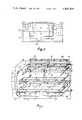
- FIG. 1is a perspective view of the basin with the front wall broken away to show the interior of the basin, also showing the frame-arm in vertical position;
- FIG. 2is a front elevation of the invention showing the basin proper in dashed outline
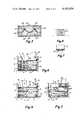
- FIG. 3is a cross-sectional view of two assembled denture flask halves containing a denture model and artificial teeth;
- FIGS. 4 to 6are similar cross-sectional end views of the basin, showing the first and second stages of the dewaxing step, and the final curing step, respectively;
- FIG. 7is a cross-sectional side view of one of the shower nozzles.
- FIG. 8is a bottom view of the shower nozzle of FIG. 7.
- the preferred embodiment of the inventioncomprises a basin 1 mounted in a suitable box-like frame 2, as suggested in FIGS. 1 and 2.
- Basin 1has a pair of opposite end walls 3, a rear wall 4, a front wall 5, a floor 6 and, preferably, an anti-vapor cover 7 (seen only in FIG. 2).
- Basin 1is adapted to be filled with fluid 8 (usually hot water).
- topmost tray 9 and middle tray 10are of a substantially lesser width than the width of basin 1 and are slidably mounted for transverse movement on guideways 13. This is to facilitate access to the lowermost tray 11.
- the latteris preferably supported above the floor 6 of basin 1 by legs 11' at each of its corners.
- An electric heating element 14is provided to heat the fluid 8. It is located under lowermost tray 11 adjacent floor 6.
- a water level sensor 15is provided in one of the end walls 3 (cf. FIG. 1) just above element 14. When the water level falls low enough in basin 1, sensor 15 activates an electric inlet valve 16 which is connected to an external water supply (not shown). Basin 1 is also provided with a drain 17 to empty the water down to the level of sensor 15, as needed.
- An upper water level limiting meanshas also been provided for in-basin 1, consisting of a second sensor 18 located in one of the end walls 3 just under topmost tray 9. When the water level reaches sensor 18, the latter shuts off inlet valve 16 automatically.
- the elements of basin 1further include a frame-arm 19 extending from end to end of basin 1 and pivotally secured thereto adjacent the upper rear edge thereof.
- Frame-arm 19is provided with a plurality of shower nozzles 20, which are adapted to spray water over the entire surface of topmost tray 9.
- Arm 19is pivotally secured by means of pins 21. These latter are of hallow construction and constitute inlet nipples for the water flowing into arm 19 which, of course, is also hollow.
- Each pin 21is connected by means of feed pipes 22 to a recirculating pump 23 located in frame 2 underneath floor 6 of the basin.
- a return pipe 24communicates with the floor 6 of basin 1 at one end and is connected to pump 23 at its other end.
- the heated water 8is pumped through shower nozzles 20, which then drains into basin 1 through return pipe 24 and back to pump 23 for recirculation.
- Flask 25is made in two halves 25' and 25" and contains a denture model consisting of wax 26 and artificial teeth 27. Both halves 25' and 25" are filled with plaster 28 and parting surfaces 29 are provided, as known.
- the dewaxing operationcan be carried out: firstly, the wax must be heated to separate the flask halves. This is done by filling basin 1 with water and placing the flasks 25 on either the middle tray 10 or lowermost tray 11, as shown in FIG. 4. When wax 26 is sufficiently hot, the flask halves are separated and placed in topmost tray 9. Frame-arm 19 is then pivoted downwardly to its horizontal spray position. A contact switch 30 is provided to activate pump 23 automatically when abutted by arm 19. (cf. FIG. 5) When all traces of wax 26 have been sprayed away by nozzles 20, the flask halves are filled with plastic denture material (not shown) and reassembled for the final curing step.
- the denturesare cured under water in basin 1 for predetermined periods of time, for example one hour at 180 degrees F. and eight hours at 160 degrees F.
- an automatic timer(not shown) is provided to turn on and off the heating element 14 according to desired curing periods; a thermostat (not shown) is also provided to maintain the curing temperature at constant degree.
- the flasks ready to be curedare placed in either the middle or lowermost trays 10 and 11 (although none are shown in the figure); the basin is filled with water 8 and heating element 14 is turned on; at the same time, flask halves, ready for final dewaxing, are placed in topmost tray 9; the frame-arm 19 is pivoted to its horizontal position, thus activating the pump 23, whereby the flask halves are sprayed clean. It will be clear as well that dewaxing and curing can be carried out in consecutive steps, if so desired.
Landscapes
- Engineering & Computer Science (AREA)
- Mechanical Engineering (AREA)
- Dental Prosthetics (AREA)
- Medicines That Contain Protein Lipid Enzymes And Other Medicines (AREA)
Abstract
Description
Claims (8)
Priority Applications (2)
| Application Number | Priority Date | Filing Date | Title |
|---|---|---|---|
| US06/389,985US4405854A (en) | 1982-06-18 | 1982-06-18 | Combined denture mold dewaxer and curing basin |
| CA000427804ACA1189661A (en) | 1982-06-18 | 1983-05-10 | Combined denture mold dewaxer and curing basin |
Applications Claiming Priority (1)
| Application Number | Priority Date | Filing Date | Title |
|---|---|---|---|
| US06/389,985US4405854A (en) | 1982-06-18 | 1982-06-18 | Combined denture mold dewaxer and curing basin |
Publications (1)
| Publication Number | Publication Date |
|---|---|
| US4405854Atrue US4405854A (en) | 1983-09-20 |
Family
ID=23540569
Family Applications (1)
| Application Number | Title | Priority Date | Filing Date |
|---|---|---|---|
| US06/389,985Expired - Fee RelatedUS4405854A (en) | 1982-06-18 | 1982-06-18 | Combined denture mold dewaxer and curing basin |
Country Status (2)
| Country | Link |
|---|---|
| US (1) | US4405854A (en) |
| CA (1) | CA1189661A (en) |
Cited By (5)
| Publication number | Priority date | Publication date | Assignee | Title |
|---|---|---|---|---|
| US5965171A (en)* | 1996-08-05 | 1999-10-12 | Satoyuki Matsushita | Apparatus and process for producing dentures having synthetic resin base |
| US6117497A (en)* | 1993-03-23 | 2000-09-12 | Tokai University | Solid surface modification method and apparatus |
| US6432215B1 (en)* | 1998-11-12 | 2002-08-13 | Mag-Chem Inc. | Fully automatic plating wax removing device and method thereof |
| US6689426B1 (en)* | 1993-03-23 | 2004-02-10 | Tokai University | Solid surface modification method and apparatus |
| US7235140B1 (en)* | 2003-08-27 | 2007-06-26 | Steve Hayes | Method for cleaning tissue processing molds |
Citations (11)
| Publication number | Priority date | Publication date | Assignee | Title |
|---|---|---|---|---|
| US2360986A (en)* | 1941-08-06 | 1944-10-24 | Taub Francis | Heat transfer in denture molds |
| US2498368A (en)* | 1946-03-22 | 1950-02-21 | Harrison Dental Company Inc | Process for curing acrylic base denture material |
| US3061898A (en)* | 1959-09-16 | 1962-11-06 | Richard K Maliszewski | Denture flask de-waxer |
| US3190944A (en)* | 1963-05-31 | 1965-06-22 | Davidson Rubber Company Inc | Method of mold temperature control |
| US3404056A (en)* | 1964-07-17 | 1968-10-01 | Howmet Corp | Formation of plastic dental appliances |
| US3415922A (en)* | 1965-07-02 | 1968-12-10 | Monsanto Co | Mist spinning |
| US3493037A (en)* | 1967-02-17 | 1970-02-03 | Peter Haake | Thermostatic apparatus |
| US3792801A (en)* | 1971-10-29 | 1974-02-19 | Nordson Corp | Thermoplastic applicator with self-cleaning supply reservoir |
| US3869595A (en)* | 1974-06-19 | 1975-03-04 | Walter Collins | Insulated heated lunch box |
| US4107359A (en)* | 1971-05-28 | 1978-08-15 | Fried. Krupp Gesellschaft Mit Beschrankter Haftung | Method of drying coated cans |
| US4370130A (en)* | 1981-07-01 | 1983-01-25 | Berger Igor A | Wax occlusal rim warmer |
- 1982
- 1982-06-18USUS06/389,985patent/US4405854A/ennot_activeExpired - Fee Related
- 1983
- 1983-05-10CACA000427804Apatent/CA1189661A/ennot_activeExpired
Patent Citations (11)
| Publication number | Priority date | Publication date | Assignee | Title |
|---|---|---|---|---|
| US2360986A (en)* | 1941-08-06 | 1944-10-24 | Taub Francis | Heat transfer in denture molds |
| US2498368A (en)* | 1946-03-22 | 1950-02-21 | Harrison Dental Company Inc | Process for curing acrylic base denture material |
| US3061898A (en)* | 1959-09-16 | 1962-11-06 | Richard K Maliszewski | Denture flask de-waxer |
| US3190944A (en)* | 1963-05-31 | 1965-06-22 | Davidson Rubber Company Inc | Method of mold temperature control |
| US3404056A (en)* | 1964-07-17 | 1968-10-01 | Howmet Corp | Formation of plastic dental appliances |
| US3415922A (en)* | 1965-07-02 | 1968-12-10 | Monsanto Co | Mist spinning |
| US3493037A (en)* | 1967-02-17 | 1970-02-03 | Peter Haake | Thermostatic apparatus |
| US4107359A (en)* | 1971-05-28 | 1978-08-15 | Fried. Krupp Gesellschaft Mit Beschrankter Haftung | Method of drying coated cans |
| US3792801A (en)* | 1971-10-29 | 1974-02-19 | Nordson Corp | Thermoplastic applicator with self-cleaning supply reservoir |
| US3869595A (en)* | 1974-06-19 | 1975-03-04 | Walter Collins | Insulated heated lunch box |
| US4370130A (en)* | 1981-07-01 | 1983-01-25 | Berger Igor A | Wax occlusal rim warmer |
Cited By (5)
| Publication number | Priority date | Publication date | Assignee | Title |
|---|---|---|---|---|
| US6117497A (en)* | 1993-03-23 | 2000-09-12 | Tokai University | Solid surface modification method and apparatus |
| US6689426B1 (en)* | 1993-03-23 | 2004-02-10 | Tokai University | Solid surface modification method and apparatus |
| US5965171A (en)* | 1996-08-05 | 1999-10-12 | Satoyuki Matsushita | Apparatus and process for producing dentures having synthetic resin base |
| US6432215B1 (en)* | 1998-11-12 | 2002-08-13 | Mag-Chem Inc. | Fully automatic plating wax removing device and method thereof |
| US7235140B1 (en)* | 2003-08-27 | 2007-06-26 | Steve Hayes | Method for cleaning tissue processing molds |
Also Published As
| Publication number | Publication date |
|---|---|
| CA1189661A (en) | 1985-07-02 |
Similar Documents
| Publication | Publication Date | Title |
|---|---|---|
| US7114943B1 (en) | Post processor for three-dimensional objects | |
| US4405854A (en) | Combined denture mold dewaxer and curing basin | |
| GB1602191A (en) | Shower assemblies | |
| EP0120044B1 (en) | Method and apparatus for processing cheese | |
| CN111789278B (en) | A dough nest forming mold and automatic dough nest processing equipment | |
| CN213406371U (en) | Full-automatic wax washing machine | |
| US2468539A (en) | Candle molding apparatus | |
| CN212260441U (en) | Dough pit forming die and automatic dough pit processing equipment | |
| JP2004242595A (en) | Cleaning apparatus for pet animal | |
| CN104381190A (en) | Fish-tank comprehensive filtration maintenance system with indoor and outdoor communication function | |
| CN113080738A (en) | Children's bath nursing pond of standing | |
| US3061898A (en) | Denture flask de-waxer | |
| US1753424A (en) | Florist's water fountain | |
| CA2359254A1 (en) | Liquid separator | |
| JP2604676B2 (en) | Dewaxing device | |
| CN205107198U (en) | Carry over tea tray of water structure out of | |
| JPH09313506A (en) | Dewaxer of false tooth mold | |
| JPS6410376B2 (en) | ||
| US2057540A (en) | Machine for molding candles | |
| GB2246511A (en) | Glass cleaning assembly | |
| US3741773A (en) | Preparation of ricotta cheese | |
| CA2229393C (en) | Eye glass cleaning machine | |
| GB2073093A (en) | Method and apparatus for making moulded articles such as dentures | |
| CN207916055U (en) | A kind of new ultra-violet photofixation 3D printer | |
| US2213335A (en) | Cleaner and sterilizer for containers |
Legal Events
| Date | Code | Title | Description |
|---|---|---|---|
| AS | Assignment | Owner name:LES ENTREPRISES DENTAIRES BALCOP INC., 170, BOULEV Free format text:ASSIGNMENT OF ASSIGNORS INTEREST.;ASSIGNOR:LAPOINTE, DENIS;REEL/FRAME:004657/0289 Effective date:19861112 Owner name:LES ENTREPRISES DENTAIRES BALCOP INC.,CANADA Free format text:ASSIGNMENT OF ASSIGNORS INTEREST;ASSIGNOR:LAPOINTE, DENIS;REEL/FRAME:004657/0289 Effective date:19861112 | |
| MAFP | Maintenance fee payment | Free format text:PAYMENT OF MAINTENANCE FEE, 4TH YEAR, PL 96-517 (ORIGINAL EVENT CODE: M170); ENTITY STATUS OF PATENT OWNER: SMALL ENTITY Year of fee payment:4 | |
| FEPP | Fee payment procedure | Free format text:PAYMENT IS IN EXCESS OF AMOUNT REQUIRED. REFUND SCHEDULED (ORIGINAL EVENT CODE: F169); ENTITY STATUS OF PATENT OWNER: SMALL ENTITY | |
| REFU | Refund | Free format text:REFUND - PAYMENT OF MAINTENANCE FEE, 8TH YEAR, PL 96-517 (ORIGINAL EVENT CODE: R171); ENTITY STATUS OF PATENT OWNER: SMALL ENTITY | |
| FEPP | Fee payment procedure | Free format text:MAINTENANCE FEE REMINDER MAILED (ORIGINAL EVENT CODE: REM.); ENTITY STATUS OF PATENT OWNER: SMALL ENTITY | |
| LAPS | Lapse for failure to pay maintenance fees | ||
| FP | Lapsed due to failure to pay maintenance fee | Effective date:19950920 | |
| STCH | Information on status: patent discontinuation | Free format text:PATENT EXPIRED DUE TO NONPAYMENT OF MAINTENANCE FEES UNDER 37 CFR 1.362 |