US4405017A - Positive locating expendable plug - Google Patents
Positive locating expendable plugDownload PDFInfo
- Publication number
- US4405017A US4405017AUS06/308,688US30868881AUS4405017AUS 4405017 AUS4405017 AUS 4405017AUS 30868881 AUS30868881 AUS 30868881AUS 4405017 AUS4405017 AUS 4405017A
- Authority
- US
- United States
- Prior art keywords
- mandrel
- sleeve means
- movement
- sleeve
- plug
- Prior art date
- Legal status (The legal status is an assumption and is not a legal conclusion. Google has not performed a legal analysis and makes no representation as to the accuracy of the status listed.)
- Expired - Fee Related
Links
- 238000000034methodMethods0.000claimsabstractdescription5
- 239000012530fluidSubstances0.000claimsdescription18
- 238000010008shearingMethods0.000claimsdescription6
- 238000007789sealingMethods0.000claimsdescription3
- 230000000694effectsEffects0.000claims3
- 239000007787solidSubstances0.000claims3
- 238000012544monitoring processMethods0.000abstractdescription3
- 238000004519manufacturing processMethods0.000description7
- 239000004576sandSubstances0.000description4
- 238000002955isolationMethods0.000description2
- 230000000712assemblyEffects0.000description1
- 238000000429assemblyMethods0.000description1
- 230000005540biological transmissionEffects0.000description1
- 238000004891communicationMethods0.000description1
- 238000010276constructionMethods0.000description1
- 238000006073displacement reactionMethods0.000description1
- 238000012986modificationMethods0.000description1
- 230000004048modificationEffects0.000description1
- 230000000284resting effectEffects0.000description1
- 238000011179visual inspectionMethods0.000description1
Images

Classifications
- E—FIXED CONSTRUCTIONS
- E21—EARTH OR ROCK DRILLING; MINING
- E21B—EARTH OR ROCK DRILLING; OBTAINING OIL, GAS, WATER, SOLUBLE OR MELTABLE MATERIALS OR A SLURRY OF MINERALS FROM WELLS
- E21B23/00—Apparatus for displacing, setting, locking, releasing or removing tools, packers or the like in boreholes or wells
- E21B23/02—Apparatus for displacing, setting, locking, releasing or removing tools, packers or the like in boreholes or wells for locking the tools or the like in landing nipples or in recesses between adjacent sections of tubing
- E—FIXED CONSTRUCTIONS
- E21—EARTH OR ROCK DRILLING; MINING
- E21B—EARTH OR ROCK DRILLING; OBTAINING OIL, GAS, WATER, SOLUBLE OR MELTABLE MATERIALS OR A SLURRY OF MINERALS FROM WELLS
- E21B23/00—Apparatus for displacing, setting, locking, releasing or removing tools, packers or the like in boreholes or wells
- E21B23/06—Apparatus for displacing, setting, locking, releasing or removing tools, packers or the like in boreholes or wells for setting packers
- E—FIXED CONSTRUCTIONS
- E21—EARTH OR ROCK DRILLING; MINING
- E21B—EARTH OR ROCK DRILLING; OBTAINING OIL, GAS, WATER, SOLUBLE OR MELTABLE MATERIALS OR A SLURRY OF MINERALS FROM WELLS
- E21B33/00—Sealing or packing boreholes or wells
- E21B33/10—Sealing or packing boreholes or wells in the borehole
- E21B33/12—Packers; Plugs
- E21B33/129—Packers; Plugs with mechanical slips for hooking into the casing
- E21B33/1294—Packers; Plugs with mechanical slips for hooking into the casing characterised by a valve, e.g. a by-pass valve
Definitions
- the present inventionrelates in general to tools for use in well packer asemblies, and in particular to expendable plugs of the type which are disengaged from a well packer by forces generated through a tubing string.
- plug assemblies for use in subterranean wellsare utilized in combination with a packer assembly and are selectively located within a well casing in order to isolate one or more of the production zones of the well.
- the plug assemblyis mounted within a packer assembly at the well head and the entire unit is run down the well casing and secured at a selected location along the casing.
- a tubing string having a suitable actuator attached to the lower end thereofis run down the well casing to contact the plug.
- the plugbecomes disengaged from the packer assembly and free falls to the bottom of the well.
- An example of such an expendable plugis disclosed in U.S. Pat. No. 4,188,999 to A. Amancharia.
- the present inventionrelates to a tool, such as an expendable plug assembly, which is released from a tubular member, such as a packer assembly in such a manner so as to provide the operator with a positive indication that the tubing string has actually located the plug.
- This indicationis provided by requiring a predetermined upward force to be applied to the plug by the tubing string before a downward force can be used to release the plug from the packer.
- the plug assemblyincludes a main housing which is utilized to support a plurality of circumferentially spaced, radially shiftable locking segments.
- the locking segmentscan be maintained in a radially outward position by means of an inner mandrel slidably mounted within the housing.
- the locking segmentsare received within a cooperating annular groove formed in the packer assembly for securely locking the plug within the packer.
- the mandrelis shiftable from an upper position wherein the locking segments are maintained outwardly in engagement with the packer assembly to a lower position wherein the locking segments can be retracted to release the plug from the packer assembly.
- the plug assemblyalso includes seal means on the main housing for preventing fluid transmission across the plug.
- a positioning meanssuch as a collet sleeve, is positioned over the upper end of the mandrel, and rests on the housing and is releasably secured to the mandrel by means of a first shear pin.
- a first shear pinIn order to shift the mandrel downwardly to its second position, an upward force must first be applied to the collet sleeve by the tubing string to shear the first shear pin permitting the collet sleeve to telescope upward relative to the mandrel.
- Both the collet sleeve and the mandrelare provided with ratchet means or wickers which, after the first shear pin has been sheared, can be engaged by upward movement of the collet sleeve to securely lock the collet sleeve to the mandrel.
- a downward force thereafter applied to the collet sleeve by the tubing stringcauses the mandrel to shift downwardly to its lower position. Downward movement of the mandrel shifts a split sleeve member, initially holding the locking segments in their radially engaged position, to dislodge the locking segments thereby permitting the plug to be released from the packer.
- the present inventionprovides an actuating sleeve which can be utilized to further assure the operator by visual inspection that he has contacted the plug.
- the actuating sleeveincludes a hollow main body attachable to the bottom of a tubing string and having a locating sleeve releasably secured to the inner wall thereof by means of a second shear pin.
- the locating sleevehas an upwardly facing shoulder which is engageable with downwardly facing shoulders on the collet arms in order to produce the required upward force to shear the first shear pin between the collet sleeve and the mandrel. Further upward force generated on the tubing string causes the second shear pin between the main body of the tubing guide and the locating sleeve to shear, thereby releasing the locating sleeve from the tubing guide and providing the operator with a second signal.
- the operatorcan examine the actuating sleeve to determine whether or not the locating sleeve has remained downhole with the plug, and if it has, the re-inserted tubing string will directly engage the interlocked collet sleeve and mandrel to force it downward to release the plug.
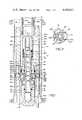
- FIG. 1is a sectional view taken through a well casing and showing the lower portion of a packer assembly in which is located an expendable plug embodying the principles of the present invention
- FIG. 2is a sectional view of the plug taken along the plane 2--2 of FIG. 1;
- FIG. 3ais a quarter sectional view, showing the plug in its locked position with a tubing guide positioned over the upper end thereof;
- FIG. 3bis a quarter sectional view, similar to FIG. 3a, but showing the relative position of the collet sleeve and the tubing guide after the connecting pin between the mandrel and the collet sleeve has been sheared;
- FIG. 3cis a quarter sectional view, similar to FIGS. 3a and 3b, but showing the relative positions of the plug components after the mandrel has been shifted downwardly to retract the locking segments.
- FIG. 1there is shown an expendable plug assembly 10 embodying the principles of the present invention which is locked within a packer assembly 12 located within a well casing 14.
- the plug assembly 10 and the packer assembly 12are positioned at a predetermined location along the well casing 14 to provide fluid isolation between an upper and lower production zone of a well.
- an actuating sleeve 16which, as will be discussed, is attached to a tubing string and utilized to release the plug assembly 10 from the packer assembly 12.
- the packer assembly 12includes a bottom packer guide 18 which is threadably secured at 18a to an upper packer body 20.
- the upper packer body 20is provided with a conventional slip assembly (not shown) which expands radially outwardly from the body 20 to grip the interior of the well casing 14 for securely mounting the packer assembly 12 at a selected location along the well casing 14.
- the upper body 20is also provided with a sealing unit (not shown) for preventing fluid flow through the well casing 14 along the outside of the packer assembly 12.
- the expendable plug assembly 10includes a main housing 22 consisting of an upper locking segment portion 24 and a lower plug portion 26 which are secured together to form a unitary body by threads 24a.
- the locking segment portion 24is provided with a plurality of circumferentially spaced, radial openings 24b for receiving a plurality of locking segments 30.
- Each locking segment 30includes an outer annular groove 30a for receiving a snap ring 32 which maintains the segment 30 within its associated opening 24b.
- Each locking segment 30further includes an outer annular rib portion 30b below the groove 30a which extends downwardly and inwardly to form a downwardly facing inclined surface 30c.
- a longitudinally extending mandrel 33 having a central passageway 33ais adapted to slidably engage an upper cylindrical bore hole 24c in the upper locking segment portion 24 and a lower cylindrical bore hole 26a in the lower plug portion 26.
- a vertically shiftable membersuch as a split sleeve 34 consisting of half sections 34a and 34b are affixed to mandrell 33 at a reduced diameter portion 33b of the mandrel.
- the mandrel 33is axially shiftable relative to the housing 22 from an upper position, as shown in FIGS. 1, 3a and 3b, to a lower position, as shown in FIG. 3c.
- the split sleeve 34 mounted thereonmaintains the locking segments 30 in a radially outward, locked position such that the annular ribs 30b of the segments 30 are received within a cooperating annular groove 18b having an upwardly facing inclined surface 18c formed in the packer assembly 12 to securely lock the plug 10 within the packer against vertical movement.
- the inner mandrel 33 and the split sleeve 34are shifted longitudinally downwardly, as discussed, the locking segments 30 are able to move radially inwardly under the bias of snap ring 32 and hence out of the groove 18b to release the plug 10 from the packer assembly 12.
- the plug assembly 10is provided with a seal means for preventing fluid flow through the interior of the packer assembly when the plug is in its locked position.
- seal meansincludes a first O-ring 35 which is sealingly mounted between the bore hole 26a and the outer wall of the lower end of the mandrel 33, a second O-ring 36 which is sealingly mounted between the bore hole 24c and the outer wall of the upper end of the mandrel 33, and a third O-ring 38 which is sealingly mounted between the outer wall of the housing 24 and the inner wall of the packer assembly 12.
- the mandrel 33is provided with a port hole 33c and the lower plug portion 26 is provided with port holes 26b which, as will be discussed, are utilized to equalize the differential fluid pressure across the plug during the releasing operation of the plug.
- the plug 10further includes a positioning means such as a collet sleeve 40 which is positioned over the upper end of the mandrel 33.
- the collet sleeve 40has an intermediate cylindrical ring portion 40a which is releasably secured to the upper end of the mandrel 33 by means of a threaded shear pin 41.
- the collet 40is provided with a plurality of circumferentially spaced, upwardly extending collet arms 40b, each having an outer annular segment shoulder portion 40c formed on the upper end thereof which extends upwardly and inwardly to form an upwardly facing bevelled surface 40d.
- the collet sleeve 40also includes a plurality of circumferentially spaced, downwardly extending collet arms 40e each having an enlarged lower end 40f adapted to abuttingly engage the upper face of the housing 24.
- the lower ends 40f of the collet arms 40eare each provided with a series of internal wicker threads 40g which are adapted to cooperate with a series of external wicker threads 33d formed on the upper end of the mandrel 33.
- the internal wickers 40gextend upwardly and terminate in a downwardly facing shoulder 40h, while the external wickers 33d on the mandrel 33 extend upwardly and terminate in a downwardly facing shoulder 33e.
- This constructionpermits the collet wickers 40g to be ratcheted upwardly onto the mandrel wickers 33d until the engagement of the shoulders 33e and 40h, but prevents any subsequent relative axial movement between the collet sleeve 40 and the mandrel 33.
- the actuating sleeve 16includes a hollow main body portion 42 having an upper end threadably secured at 42a to the lower end of a tubing string 44 which extends downwardly from the well head.
- the main body portion 42surrounds a locating sleeve 46 which is releasably secured to the inner wall of the main body portion 42 by means of a threaded shear pin 48.
- the main body portionhas an downwardly facing inner shoulder 42b which engages the upwardly facing end surface 46a of the sleeve 46 to prevent upward axial movement of the sleeve 46 relative to the main body portion 42.
- the locating sleeve 46has a downwardly facing bevelled surface 46b formed on the lower end thereof.
- the shear pin 48requires a greater shearing force than the shear pin 41 connecting the mandrel 33 and the collet sleeve 40.
- the plug 10 and the packer 12are assembled at the well head as one unit with the locking segments 30 expanded radially outwardly into the annular groove 18b of the packer.
- the entire unitis then lowered down the well casing on a tubing string and the packer assembly 12 is secured at a selected location along the well casing 14, which location is typically between an upper and lower production zone of a well. Once secured, the plug 10 and the packer 12 will provide fluid isolation between the upper and lower production zones to permit independent production or treatment of the two zones.
- a control element or work stringsuch as the tubing string 44 is lowered down the well casing 14 with the actuating sleeve 16 attached to the lower end thereof.
- the sleeve 16is then run over the upper end of the collet sleeve 40 until the bevelled surface 46b on the locating sleeve 46 contacts the bevelled surface 40d at the upper end of the collet sleeve 40.
- the plug 10When the actuating sleeve 16 has contacted the lower end 40f of the collet sleeve 40, the plug 10 will resist any further downward movement of the actuating sleeve 16 and the tubing string 44.
- the operator at the well headcan be assured that the tubing guide has contacted the plug 10 by lifting the tubing string upwardly, such that the upper end surface 46a of the locating sleeve 46 will contact the shoulder portions 40c formed at the upper ends of the collet arms 40b.
- a first predetermined amount of upward force applied to the actuating sleeve 16causes the pin 41 to shear, so that the collet sleeve 40 is moved axially upwardly relative to the mandrel 33.
- Such shearingprovides the operator with a reliable signal that the tubing string is in engagement with the plug 10.
- the wicker threads 40g at the lower end of the lower collet arms 40ewill be ratcheted onto the wicker threads 33d formed at the upper end of the mandrel 33. Further upward movement of the collet sleeve 40 will stop when the upwardly facing shoulder 40h engages the downwardly facing shoulder 33e, as shown in FIG. 3b.
- a second predetermined amount of upward forceis required to shear the pin 48 and thus release the actuating sleeve 16 from the plug 10.
- the operatorcan be assured that the actuating sleeve 16 has engaged the plug 10. If the tubing string is then lifted from the well casing the operator can be further assured that the actuating sleeve 16 has contacted the plug 10 by examining the actuating sleeve 16 after it has been removed from the well casing to determine whether the locating sleeve 46 has remained downhole.
- the actuating sleeve 16is then re-lowered down the well casing 14 until the lower end 42c of the main body 42 contacts the upper surfaces 40i of the lower ends 40f of the collet sleeve 40. Further downward movement of the actuating sleeve 16 causes the interlocked collet sleeve 40 and the mandrel 33 to be shifted axially downwardly such that the split sleeve 34 is moved out of engagement with the locking segments 30, as shown in FIG. 3c. As the tubing string is moved downwardly, the locking segments 30 are urged radially inwardly by the engagement of the inclined surfaces 30c with the inclined surface 18c of the groove 18b and by snap ring 32. The plug assembly 10 is released from engagement with the packer assembly 12 and can then free fall within the well casing 14 to the bottom of the well.
- the port 33cwhich has previously been located above the O-rings 36 and 38 and thus exposed to the fluid source above the plug, will now be positioned below the O-rings 36 and 38 such that the fluid source below the plug is in fluid communication with the upper fluid source via the ports 26b and 33c and the mandrel central passageway 33a. Consequently, if there is any differential pressure between the upper and lower fluid sources, this pressure can be equalized in order to facilitate the disengagement of the locking segments 30.
- the latching assemblycan be released by other means.
- a member having a radial dimension less than the inner diameter of upstanding collet figures 40bcan be inserted between the collet fingers to abut the upper end of mandrel 33.
- a downward jarring force applied to mandrel 33shears screw 41. The mandrel is then free to move downward relative to sleeve 40 to release locking members 30.
Landscapes
- Life Sciences & Earth Sciences (AREA)
- Engineering & Computer Science (AREA)
- Geology (AREA)
- Mining & Mineral Resources (AREA)
- Physics & Mathematics (AREA)
- Environmental & Geological Engineering (AREA)
- Fluid Mechanics (AREA)
- General Life Sciences & Earth Sciences (AREA)
- Geochemistry & Mineralogy (AREA)
- Earth Drilling (AREA)
Abstract
Description
Claims (26)
Priority Applications (1)
| Application Number | Priority Date | Filing Date | Title |
|---|---|---|---|
| US06/308,688US4405017A (en) | 1981-10-02 | 1981-10-02 | Positive locating expendable plug |
Applications Claiming Priority (1)
| Application Number | Priority Date | Filing Date | Title |
|---|---|---|---|
| US06/308,688US4405017A (en) | 1981-10-02 | 1981-10-02 | Positive locating expendable plug |
Publications (1)
| Publication Number | Publication Date |
|---|---|
| US4405017Atrue US4405017A (en) | 1983-09-20 |
Family
ID=23194986
Family Applications (1)
| Application Number | Title | Priority Date | Filing Date |
|---|---|---|---|
| US06/308,688Expired - Fee RelatedUS4405017A (en) | 1981-10-02 | 1981-10-02 | Positive locating expendable plug |
Country Status (1)
| Country | Link |
|---|---|
| US (1) | US4405017A (en) |
Cited By (36)
| Publication number | Priority date | Publication date | Assignee | Title |
|---|---|---|---|---|
| US4500117A (en)* | 1982-11-24 | 1985-02-19 | Shell Oil Company | Pipeline connector |
| US4718488A (en)* | 1987-03-12 | 1988-01-12 | Camco, Incorporated | Pump-out plug system for a well conduit |
| US4928761A (en)* | 1989-07-17 | 1990-05-29 | Otis Engineering Corporation | Two-way plugs for wells |
| US5148867A (en)* | 1991-06-17 | 1992-09-22 | Concoyle Oil Fields Tools, Inc. | Stop for an oil well swabbing device |
| US5181569A (en)* | 1992-03-23 | 1993-01-26 | Otis Engineering Corporation | Pressure operated valve |
| US5253706A (en)* | 1990-12-29 | 1993-10-19 | Well-Equip Limited | Release mechanism |
| GB2281752A (en)* | 1993-09-14 | 1995-03-15 | Omega Dev & Eng Ltd | Plug valve assembly |
| US5909769A (en)* | 1996-02-13 | 1999-06-08 | Halliburton Energy Services, Inc. | Fluid loss device |
| US5924741A (en)* | 1996-09-06 | 1999-07-20 | Alcatel | Weaklink device for elongated offshore articles |
| US6651738B1 (en)* | 2002-05-29 | 2003-11-25 | Baker Hughes Incoporated | Downhole isolation device with retained valve member |
| US20050241710A1 (en)* | 2002-02-08 | 2005-11-03 | Ciaran Early | Apparatus for pipeline isolation |
| US20060086086A1 (en)* | 2003-12-05 | 2006-04-27 | Harald Syse | Hydraulic cylinders and plug with hydraulic cylinder |
| US8079413B2 (en) | 2008-12-23 | 2011-12-20 | W. Lynn Frazier | Bottom set downhole plug |
| US8307892B2 (en) | 2009-04-21 | 2012-11-13 | Frazier W Lynn | Configurable inserts for downhole plugs |
| US8496052B2 (en) | 2008-12-23 | 2013-07-30 | Magnum Oil Tools International, Ltd. | Bottom set down hole tool |
| USD694280S1 (en) | 2011-07-29 | 2013-11-26 | W. Lynn Frazier | Configurable insert for a downhole plug |
| USD694281S1 (en) | 2011-07-29 | 2013-11-26 | W. Lynn Frazier | Lower set insert with a lower ball seat for a downhole plug |
| USD698370S1 (en) | 2011-07-29 | 2014-01-28 | W. Lynn Frazier | Lower set caged ball insert for a downhole plug |
| USD703713S1 (en) | 2011-07-29 | 2014-04-29 | W. Lynn Frazier | Configurable caged ball insert for a downhole tool |
| US8899317B2 (en) | 2008-12-23 | 2014-12-02 | W. Lynn Frazier | Decomposable pumpdown ball for downhole plugs |
| EP2873801A1 (en)* | 2013-11-18 | 2015-05-20 | Weatherford/Lamb Inc. | Telemetry operated cementing plug release system |
| US9109428B2 (en) | 2009-04-21 | 2015-08-18 | W. Lynn Frazier | Configurable bridge plugs and methods for using same |
| US9127527B2 (en) | 2009-04-21 | 2015-09-08 | W. Lynn Frazier | Decomposable impediments for downhole tools and methods for using same |
| US9163477B2 (en) | 2009-04-21 | 2015-10-20 | W. Lynn Frazier | Configurable downhole tools and methods for using same |
| US9181772B2 (en) | 2009-04-21 | 2015-11-10 | W. Lynn Frazier | Decomposable impediments for downhole plugs |
| US9217319B2 (en) | 2012-05-18 | 2015-12-22 | Frazier Technologies, L.L.C. | High-molecular-weight polyglycolides for hydrocarbon recovery |
| USRE46028E1 (en) | 2003-05-15 | 2016-06-14 | Kureha Corporation | Method and apparatus for delayed flow or pressure change in wells |
| US9428998B2 (en) | 2013-11-18 | 2016-08-30 | Weatherford Technology Holdings, Llc | Telemetry operated setting tool |
| US9506309B2 (en) | 2008-12-23 | 2016-11-29 | Frazier Ball Invention, LLC | Downhole tools having non-toxic degradable elements |
| US9528346B2 (en) | 2013-11-18 | 2016-12-27 | Weatherford Technology Holdings, Llc | Telemetry operated ball release system |
| US9546535B2 (en) | 2014-12-16 | 2017-01-17 | Baker Hughes Incorporated | Packer plug with retractable latch, downhole system, and method of retracting packer plug from packer |
| US9562415B2 (en) | 2009-04-21 | 2017-02-07 | Magnum Oil Tools International, Ltd. | Configurable inserts for downhole plugs |
| US9587475B2 (en) | 2008-12-23 | 2017-03-07 | Frazier Ball Invention, LLC | Downhole tools having non-toxic degradable elements and their methods of use |
| US9708878B2 (en) | 2003-05-15 | 2017-07-18 | Kureha Corporation | Applications of degradable polymer for delayed mechanical changes in wells |
| US9777569B2 (en) | 2013-11-18 | 2017-10-03 | Weatherford Technology Holdings, Llc | Running tool |
| US12416209B2 (en)* | 2021-04-27 | 2025-09-16 | Interwell Norway As | Well tool comprising an anchoring device and method for using |
Citations (3)
| Publication number | Priority date | Publication date | Assignee | Title |
|---|---|---|---|---|
| US2894586A (en)* | 1955-02-02 | 1959-07-14 | Otis Eng Co | Well tools |
| US3148894A (en)* | 1958-06-26 | 1964-09-15 | Otis Eng Co | Well tools |
| US4307902A (en)* | 1979-07-13 | 1981-12-29 | Otis Engineering Corp. | Riser connector |
- 1981
- 1981-10-02USUS06/308,688patent/US4405017A/ennot_activeExpired - Fee Related
Patent Citations (3)
| Publication number | Priority date | Publication date | Assignee | Title |
|---|---|---|---|---|
| US2894586A (en)* | 1955-02-02 | 1959-07-14 | Otis Eng Co | Well tools |
| US3148894A (en)* | 1958-06-26 | 1964-09-15 | Otis Eng Co | Well tools |
| US4307902A (en)* | 1979-07-13 | 1981-12-29 | Otis Engineering Corp. | Riser connector |
Cited By (53)
| Publication number | Priority date | Publication date | Assignee | Title |
|---|---|---|---|---|
| US4500117A (en)* | 1982-11-24 | 1985-02-19 | Shell Oil Company | Pipeline connector |
| US4718488A (en)* | 1987-03-12 | 1988-01-12 | Camco, Incorporated | Pump-out plug system for a well conduit |
| US4928761A (en)* | 1989-07-17 | 1990-05-29 | Otis Engineering Corporation | Two-way plugs for wells |
| GB2233997A (en)* | 1989-07-17 | 1991-01-23 | Otis Eng Co | Two-way plugs for wells |
| GB2233997B (en)* | 1989-07-17 | 1993-02-10 | Otis Eng Co | Two-way plugs for wells |
| US5253706A (en)* | 1990-12-29 | 1993-10-19 | Well-Equip Limited | Release mechanism |
| US5148867A (en)* | 1991-06-17 | 1992-09-22 | Concoyle Oil Fields Tools, Inc. | Stop for an oil well swabbing device |
| US5181569A (en)* | 1992-03-23 | 1993-01-26 | Otis Engineering Corporation | Pressure operated valve |
| GB2281752A (en)* | 1993-09-14 | 1995-03-15 | Omega Dev & Eng Ltd | Plug valve assembly |
| GB2281752B (en)* | 1993-09-14 | 1996-07-31 | Omega Dev & Eng Ltd | Plug valve assembly |
| US5909769A (en)* | 1996-02-13 | 1999-06-08 | Halliburton Energy Services, Inc. | Fluid loss device |
| US5924741A (en)* | 1996-09-06 | 1999-07-20 | Alcatel | Weaklink device for elongated offshore articles |
| US20050241710A1 (en)* | 2002-02-08 | 2005-11-03 | Ciaran Early | Apparatus for pipeline isolation |
| US6651738B1 (en)* | 2002-05-29 | 2003-11-25 | Baker Hughes Incoporated | Downhole isolation device with retained valve member |
| US20030221824A1 (en)* | 2002-05-29 | 2003-12-04 | Solfronk Matthew D. | Downhole isolation device with retained valve member |
| USRE46028E1 (en) | 2003-05-15 | 2016-06-14 | Kureha Corporation | Method and apparatus for delayed flow or pressure change in wells |
| US10280703B2 (en) | 2003-05-15 | 2019-05-07 | Kureha Corporation | Applications of degradable polymer for delayed mechanical changes in wells |
| US9708878B2 (en) | 2003-05-15 | 2017-07-18 | Kureha Corporation | Applications of degradable polymer for delayed mechanical changes in wells |
| US20060086086A1 (en)* | 2003-12-05 | 2006-04-27 | Harald Syse | Hydraulic cylinders and plug with hydraulic cylinder |
| US7568504B2 (en)* | 2003-12-05 | 2009-08-04 | Tdw Offshore Services As | Hydraulic cylinders and plug with hydraulic cylinder |
| US8899317B2 (en) | 2008-12-23 | 2014-12-02 | W. Lynn Frazier | Decomposable pumpdown ball for downhole plugs |
| US8079413B2 (en) | 2008-12-23 | 2011-12-20 | W. Lynn Frazier | Bottom set downhole plug |
| USD694282S1 (en) | 2008-12-23 | 2013-11-26 | W. Lynn Frazier | Lower set insert for a downhole plug for use in a wellbore |
| US8459346B2 (en) | 2008-12-23 | 2013-06-11 | Magnum Oil Tools International Ltd | Bottom set downhole plug |
| USD697088S1 (en) | 2008-12-23 | 2014-01-07 | W. Lynn Frazier | Lower set insert for a downhole plug for use in a wellbore |
| US9309744B2 (en) | 2008-12-23 | 2016-04-12 | Magnum Oil Tools International, Ltd. | Bottom set downhole plug |
| US9587475B2 (en) | 2008-12-23 | 2017-03-07 | Frazier Ball Invention, LLC | Downhole tools having non-toxic degradable elements and their methods of use |
| US8496052B2 (en) | 2008-12-23 | 2013-07-30 | Magnum Oil Tools International, Ltd. | Bottom set down hole tool |
| US9506309B2 (en) | 2008-12-23 | 2016-11-29 | Frazier Ball Invention, LLC | Downhole tools having non-toxic degradable elements |
| US9062522B2 (en) | 2009-04-21 | 2015-06-23 | W. Lynn Frazier | Configurable inserts for downhole plugs |
| US9109428B2 (en) | 2009-04-21 | 2015-08-18 | W. Lynn Frazier | Configurable bridge plugs and methods for using same |
| US9127527B2 (en) | 2009-04-21 | 2015-09-08 | W. Lynn Frazier | Decomposable impediments for downhole tools and methods for using same |
| US9163477B2 (en) | 2009-04-21 | 2015-10-20 | W. Lynn Frazier | Configurable downhole tools and methods for using same |
| US9181772B2 (en) | 2009-04-21 | 2015-11-10 | W. Lynn Frazier | Decomposable impediments for downhole plugs |
| US9562415B2 (en) | 2009-04-21 | 2017-02-07 | Magnum Oil Tools International, Ltd. | Configurable inserts for downhole plugs |
| US8307892B2 (en) | 2009-04-21 | 2012-11-13 | Frazier W Lynn | Configurable inserts for downhole plugs |
| USD698370S1 (en) | 2011-07-29 | 2014-01-28 | W. Lynn Frazier | Lower set caged ball insert for a downhole plug |
| USD703713S1 (en) | 2011-07-29 | 2014-04-29 | W. Lynn Frazier | Configurable caged ball insert for a downhole tool |
| USD694280S1 (en) | 2011-07-29 | 2013-11-26 | W. Lynn Frazier | Configurable insert for a downhole plug |
| USD694281S1 (en) | 2011-07-29 | 2013-11-26 | W. Lynn Frazier | Lower set insert with a lower ball seat for a downhole plug |
| US9217319B2 (en) | 2012-05-18 | 2015-12-22 | Frazier Technologies, L.L.C. | High-molecular-weight polyglycolides for hydrocarbon recovery |
| US9528346B2 (en) | 2013-11-18 | 2016-12-27 | Weatherford Technology Holdings, Llc | Telemetry operated ball release system |
| EP2873801A1 (en)* | 2013-11-18 | 2015-05-20 | Weatherford/Lamb Inc. | Telemetry operated cementing plug release system |
| AU2014259559B2 (en)* | 2013-11-18 | 2016-07-28 | Weatherford Technology Holdings, Llc | Telemetry operated cementing plug release system |
| US9523258B2 (en) | 2013-11-18 | 2016-12-20 | Weatherford Technology Holdings, Llc | Telemetry operated cementing plug release system |
| US9777569B2 (en) | 2013-11-18 | 2017-10-03 | Weatherford Technology Holdings, Llc | Running tool |
| US9970251B2 (en) | 2013-11-18 | 2018-05-15 | Weatherford Technology Holdings, Llc | Telemetry operated setting tool |
| US10221638B2 (en) | 2013-11-18 | 2019-03-05 | Weatherford Technology Holdings, Llc | Telemetry operated cementing plug release system |
| US10246965B2 (en) | 2013-11-18 | 2019-04-02 | Weatherford Technology Holdings, Llc | Telemetry operated ball release system |
| US9428998B2 (en) | 2013-11-18 | 2016-08-30 | Weatherford Technology Holdings, Llc | Telemetry operated setting tool |
| US10422216B2 (en) | 2013-11-18 | 2019-09-24 | Weatherford Technology Holdings, Llc | Telemetry operated running tool |
| US9546535B2 (en) | 2014-12-16 | 2017-01-17 | Baker Hughes Incorporated | Packer plug with retractable latch, downhole system, and method of retracting packer plug from packer |
| US12416209B2 (en)* | 2021-04-27 | 2025-09-16 | Interwell Norway As | Well tool comprising an anchoring device and method for using |
Similar Documents
| Publication | Publication Date | Title |
|---|---|---|
| US4405017A (en) | Positive locating expendable plug | |
| US5479989A (en) | Sleeve valve flow control device with locator shifter | |
| US4516634A (en) | Hydraulic running and setting tool for well packer | |
| US4944351A (en) | Downhole safety valve for subterranean well and method | |
| EP0121566B1 (en) | Retrievable inside blowout preventer valve apparatus | |
| US4487258A (en) | Hydraulically set well packer | |
| US5343956A (en) | Coiled tubing set and released resettable inflatable bridge plug | |
| US4289200A (en) | Retrievable well apparatus | |
| US5163514A (en) | Blowout preventer isolation test tool | |
| US4508167A (en) | Selective casing bore receptacle | |
| US4510995A (en) | Downhole locking apparatus | |
| US6739398B1 (en) | Liner hanger running tool and method | |
| US3796260A (en) | Multiple plug release system | |
| US8146672B2 (en) | Method and apparatus for retrieving and installing a drill lock assembly for casing drilling | |
| US3874634A (en) | Well safety valve system | |
| US5372201A (en) | Annulus pressure actuated casing hanger running tool | |
| US5327965A (en) | Wellhead completion system | |
| US5653289A (en) | Adjustable jackup drilling system hanger | |
| US4558895A (en) | Pulling tool | |
| US4570707A (en) | Releasable latch for downhole well tools | |
| US3990511A (en) | Well safety valve system | |
| US3593784A (en) | Anchor assembly for well tools such as packers and the like | |
| US3633670A (en) | Tool string assembly for use in wells | |
| US4488596A (en) | Locking apparatus for use in a subterranean well | |
| US4248300A (en) | Method of and apparatus for positioning retrievable landing nipple in a well bore string |
Legal Events
| Date | Code | Title | Description |
|---|---|---|---|
| AS | Assignment | Owner name:BAKER INTERNATIONAL CORPORATION, 500 CITY PARKWAY Free format text:ASSIGNMENT OF ASSIGNORS INTEREST.;ASSIGNORS:ALLEN, RICHARD G.;GLASER, MARK C.;REEL/FRAME:004112/0631 Effective date:19810929 | |
| MAFP | Maintenance fee payment | Free format text:PAYMENT OF MAINTENANCE FEE, 4TH YEAR, PL 96-517 (ORIGINAL EVENT CODE: M170); ENTITY STATUS OF PATENT OWNER: LARGE ENTITY Year of fee payment:4 | |
| FEPP | Fee payment procedure | Free format text:PAYOR NUMBER ASSIGNED (ORIGINAL EVENT CODE: ASPN); ENTITY STATUS OF PATENT OWNER: LARGE ENTITY | |
| FEPP | Fee payment procedure | Free format text:SURCHARGE FOR LATE PAYMENT, PL 96-517 (ORIGINAL EVENT CODE: M176); ENTITY STATUS OF PATENT OWNER: LARGE ENTITY | |
| MAFP | Maintenance fee payment | Free format text:PAYMENT OF MAINTENANCE FEE, 8TH YEAR, PL 96-517 (ORIGINAL EVENT CODE: M171); ENTITY STATUS OF PATENT OWNER: LARGE ENTITY Year of fee payment:8 | |
| FEPP | Fee payment procedure | Free format text:PAYER NUMBER DE-ASSIGNED (ORIGINAL EVENT CODE: RMPN); ENTITY STATUS OF PATENT OWNER: LARGE ENTITY | |
| FEPP | Fee payment procedure | Free format text:PAYOR NUMBER ASSIGNED (ORIGINAL EVENT CODE: ASPN); ENTITY STATUS OF PATENT OWNER: LARGE ENTITY | |
| FEPP | Fee payment procedure | Free format text:MAINTENANCE FEE REMINDER MAILED (ORIGINAL EVENT CODE: REM.); ENTITY STATUS OF PATENT OWNER: LARGE ENTITY | |
| LAPS | Lapse for failure to pay maintenance fees | ||
| FP | Lapsed due to failure to pay maintenance fee | Effective date:19950920 | |
| STCH | Information on status: patent discontinuation | Free format text:PATENT EXPIRED DUE TO NONPAYMENT OF MAINTENANCE FEES UNDER 37 CFR 1.362 |