US4404516A - System for detecting leaks from liquid-containing reservoirs and conduits - Google Patents
System for detecting leaks from liquid-containing reservoirs and conduitsDownload PDFInfo
- Publication number
- US4404516A US4404516AUS06/298,414US29841481AUS4404516AUS 4404516 AUS4404516 AUS 4404516AUS 29841481 AUS29841481 AUS 29841481AUS 4404516 AUS4404516 AUS 4404516A
- Authority
- US
- United States
- Prior art keywords
- wires
- liquid
- conductive members
- conductive
- detection
- Prior art date
- Legal status (The legal status is an assumption and is not a legal conclusion. Google has not performed a legal analysis and makes no representation as to the accuracy of the status listed.)
- Expired - Lifetime
Links
- 239000007788liquidSubstances0.000titleclaimsdescription21
- 238000001514detection methodMethods0.000claimsabstractdescription39
- 239000000126substanceSubstances0.000claimsabstractdescription33
- 230000008859changeEffects0.000claimsabstractdescription20
- 239000000463materialSubstances0.000claimsabstractdescription18
- 238000000034methodMethods0.000claimsdescription26
- 239000004744fabricSubstances0.000claimsdescription17
- 239000002699waste materialSubstances0.000claimsdescription14
- 239000004746geotextileSubstances0.000claimsdescription13
- 238000012544monitoring processMethods0.000claimsdescription12
- 239000004576sandSubstances0.000claimsdescription9
- 239000002894chemical wasteSubstances0.000claimsdescription5
- 239000011248coating agentSubstances0.000claimsdescription3
- 238000000576coating methodMethods0.000claimsdescription3
- 230000015556catabolic processEffects0.000claims5
- 238000006731degradation reactionMethods0.000claims5
- 230000000593degrading effectEffects0.000claims2
- 239000011148porous materialSubstances0.000claims1
- 238000009413insulationMethods0.000abstractdescription4
- 235000021028berryNutrition0.000description11
- 239000004020conductorSubstances0.000description10
- 239000002689soilSubstances0.000description10
- 239000012530fluidSubstances0.000description8
- 229910052751metalInorganic materials0.000description6
- 239000002184metalSubstances0.000description6
- 239000011888foilSubstances0.000description4
- 239000003960organic solventSubstances0.000description4
- 229920001059synthetic polymerPolymers0.000description4
- XLYOFNOQVPJJNP-UHFFFAOYSA-NwaterSubstancesOXLYOFNOQVPJJNP-UHFFFAOYSA-N0.000description4
- HEMHJVSKTPXQMS-UHFFFAOYSA-MSodium hydroxideChemical compound[OH-].[Na+]HEMHJVSKTPXQMS-UHFFFAOYSA-M0.000description3
- 229910000831SteelInorganic materials0.000description3
- 229910052782aluminiumInorganic materials0.000description3
- XAGFODPZIPBFFR-UHFFFAOYSA-NaluminiumChemical compound[Al]XAGFODPZIPBFFR-UHFFFAOYSA-N0.000description3
- 229920001971elastomerPolymers0.000description3
- 239000003673groundwaterSubstances0.000description3
- 230000004807localizationEffects0.000description3
- 239000010959steelSubstances0.000description3
- 239000002253acidSubstances0.000description2
- 230000009471actionEffects0.000description2
- 238000011109contaminationMethods0.000description2
- 230000007547defectEffects0.000description2
- 239000003792electrolyteSubstances0.000description2
- 229920001903high density polyethylenePolymers0.000description2
- 239000000203mixtureSubstances0.000description2
- 239000012811non-conductive materialSubstances0.000description2
- 230000009972noncorrosive effectEffects0.000description2
- 239000003209petroleum derivativeSubstances0.000description2
- 239000004033plasticSubstances0.000description2
- 229920003023plasticPolymers0.000description2
- 229920000642polymerPolymers0.000description2
- 229920005989resinPolymers0.000description2
- 239000011347resinSubstances0.000description2
- 150000003839saltsChemical class0.000description2
- 229920006395saturated elastomerPolymers0.000description2
- RYGMFSIKBFXOCR-UHFFFAOYSA-NCopperChemical compound[Cu]RYGMFSIKBFXOCR-UHFFFAOYSA-N0.000description1
- 239000000853adhesiveSubstances0.000description1
- 230000001070adhesive effectEffects0.000description1
- 230000004075alterationEffects0.000description1
- 238000013459approachMethods0.000description1
- 230000004888barrier functionEffects0.000description1
- 230000015572biosynthetic processEffects0.000description1
- 239000006227byproductSubstances0.000description1
- 239000000919ceramicSubstances0.000description1
- 238000010276constructionMethods0.000description1
- 229910052802copperInorganic materials0.000description1
- 239000010949copperSubstances0.000description1
- 230000007797corrosionEffects0.000description1
- 238000005260corrosionMethods0.000description1
- 239000010779crude oilSubstances0.000description1
- 230000003247decreasing effectEffects0.000description1
- 230000001419dependent effectEffects0.000description1
- 230000006866deteriorationEffects0.000description1
- 239000003344environmental pollutantSubstances0.000description1
- 239000000835fiberSubstances0.000description1
- 239000002657fibrous materialSubstances0.000description1
- 239000003365glass fiberSubstances0.000description1
- 239000012212insulatorSubstances0.000description1
- 239000002655kraft paperSubstances0.000description1
- 239000003949liquefied natural gasSubstances0.000description1
- 230000007774longtermEffects0.000description1
- 238000004519manufacturing processMethods0.000description1
- 239000011159matrix materialSubstances0.000description1
- 238000012986modificationMethods0.000description1
- 230000004048modificationEffects0.000description1
- 229920001778nylonPolymers0.000description1
- 230000002093peripheral effectEffects0.000description1
- 239000003208petroleumSubstances0.000description1
- 229920000728polyesterPolymers0.000description1
- 229920001225polyester resinPolymers0.000description1
- 239000004645polyester resinSubstances0.000description1
- 229920000915polyvinyl chloridePolymers0.000description1
- 239000004800polyvinyl chlorideSubstances0.000description1
- 230000008439repair processEffects0.000description1
- 239000002904solventSubstances0.000description1
- 229920002994synthetic fiberPolymers0.000description1
- 239000004758synthetic textileSubstances0.000description1
- 238000012360testing methodMethods0.000description1
- 238000009736wettingMethods0.000description1
- 238000004804windingMethods0.000description1
Images

Classifications
- G—PHYSICS
- G01—MEASURING; TESTING
- G01M—TESTING STATIC OR DYNAMIC BALANCE OF MACHINES OR STRUCTURES; TESTING OF STRUCTURES OR APPARATUS, NOT OTHERWISE PROVIDED FOR
- G01M3/00—Investigating fluid-tightness of structures
- G01M3/02—Investigating fluid-tightness of structures by using fluid or vacuum
- G01M3/04—Investigating fluid-tightness of structures by using fluid or vacuum by detecting the presence of fluid at the leakage point
- G01M3/16—Investigating fluid-tightness of structures by using fluid or vacuum by detecting the presence of fluid at the leakage point using electric detection means
- G—PHYSICS
- G01—MEASURING; TESTING
- G01M—TESTING STATIC OR DYNAMIC BALANCE OF MACHINES OR STRUCTURES; TESTING OF STRUCTURES OR APPARATUS, NOT OTHERWISE PROVIDED FOR
- G01M3/00—Investigating fluid-tightness of structures
- G01M3/02—Investigating fluid-tightness of structures by using fluid or vacuum
- G01M3/04—Investigating fluid-tightness of structures by using fluid or vacuum by detecting the presence of fluid at the leakage point
- G01M3/042—Investigating fluid-tightness of structures by using fluid or vacuum by detecting the presence of fluid at the leakage point by using materials which expand, contract, disintegrate, or decompose in contact with a fluid
- G01M3/045—Investigating fluid-tightness of structures by using fluid or vacuum by detecting the presence of fluid at the leakage point by using materials which expand, contract, disintegrate, or decompose in contact with a fluid with electrical detection means
- G—PHYSICS
- G01—MEASURING; TESTING
- G01M—TESTING STATIC OR DYNAMIC BALANCE OF MACHINES OR STRUCTURES; TESTING OF STRUCTURES OR APPARATUS, NOT OTHERWISE PROVIDED FOR
- G01M3/00—Investigating fluid-tightness of structures
- G01M3/02—Investigating fluid-tightness of structures by using fluid or vacuum
- G01M3/04—Investigating fluid-tightness of structures by using fluid or vacuum by detecting the presence of fluid at the leakage point
- G01M3/16—Investigating fluid-tightness of structures by using fluid or vacuum by detecting the presence of fluid at the leakage point using electric detection means
- G01M3/18—Investigating fluid-tightness of structures by using fluid or vacuum by detecting the presence of fluid at the leakage point using electric detection means for pipes, cables or tubes; for pipe joints or seals; for valves; for welds; for containers, e.g. radiators
Definitions
- the present inventionrelates generally to a leak detection and location system for chemical storage reservoirs, tanks and conduits containing environmentally harmful materials.
- Environmentally harmful materialssuch as chemical wastes, are sometimes stored in man-made waste chemical disposal ponds or waste tanks. These containers are generally lined with an impermeable synthetic polymer sheet that prevents the waste chemicals from corroding the tank or contaminating the ground water. Also, pipes and other types of conduits used to transport corrosive chemicals may be similarly lined.
- One of the problems that has hampered the safe storage and transportation of chemicals in this fashionis that the lining of the pond, tank or conduit can develop leaks and, before the leak can be detected, release harmful materials to pollute the earth and ground water.
- defects in the liningcan only be detected when the pond is empty by connecting the metal foil with an electrical lead, placing a second electrical lead in contact with a sponge containing an electrolyte, connecting the two leads to a power source, and tracing the entire liner surface with the sponge. Then when the sponge comes in contact with a defect in the lining, the electrolyte penetrates the lining and completes an electrical circuit, again triggering an alarm.
- Another method devised for detecting leaks from subterranean chemical tanksis to place a cured polyester resin sheet on the ground directly beneath the storage tank.
- the resin sheetis constructed with a drainage system such that leaks from the tank can be detected by inspecting a convenient portion of the drainage system where the fluid will ultimately flow.
- a salt-water reservoire.g., an earthen pit
- a resin-coated pad of corrugated cardboard, heavy kraft paper or some foamed materialcan be lined with a resin-coated pad of corrugated cardboard, heavy kraft paper or some foamed material.
- a grid of parallel wiresis placed beneath the pad, which grid may be separated by a layer of dry earth from a second, similar grid arranged so that its wires run at cross-angles to the wires of the first grid. Alternatively, the second grid may run within the pad itself.
- Berryteaches that when a break develops in the pad, the leaking salt water will establish a low-resistance shunt between one or more wires of the first grid and at least one wire of the second grid. As a result, a circuit is completed between the previously isolated grids by the leak, which, according to Berry, can be localized in two dimensions beneath the pad by attempting to pass current through successive pairs of wires in the two grids.
- the method for leak detection disclosed by Berryis dependent upon the formation by a leaking electrolytic fluid of a short-circuit across some barrier separating the two grids, at least one of which is in contact with the soil beneath the lined reservoir. Consequently, this approach requires that the soil under the reservoir remain dry, since it is the wetting of the soil by the leaking fluid that completes the circuit, thereby permitting the detection of a change in electrical resistance between the grids. Since soil under reservoirs, tanks and the like is usually moist in most parts of North America for at least part of the year, the method of Berry is not practical in many situations, and therefore has not been utilized commercially to any significant extent.
- Van Riemsdijk et aldiscloses a method for detecting leaks in the heat-insulating lining of a container for cold liquids like liquefied natural gas, whereby a plurality of frangible electrical conductors are incorporated into the heat-insulating lining of woven glass fiber.
- Van Riemsdijk et alwhen a crack develops in the lining, one or more of the conductors is broken, triggering an alarm. Van Riemsdijk et al teaches that the crack could then be located within the network of frangible conductors.
- the leak detection method disclosed by Van Riemsdijk et aldepends on a physical break in the network being caused by the crack's forming in the lining, and does not contemplate a change in the network's electrical properties as a function of contact between the network and liquid leaking from the lined container.
- Van Riemsdijk et alis intended for use in detecting leaks in liners of rigid containers, and therefore could not be employed advantageously in situations where substantial liner flexibility would be required.
- the ground beneath earthen storage reservoirs and buried pipelinesmay shift as much as six to eight inches, upwards or downwards, as the soil alternatively settles or becomes saturated. Consequently, the leak detection method taught by Van Riemsdijk et al, which utilizes a frangible conductive network, could not be applied in practice to chemical storage and transportation that are subject to movement caused by shifting soil.
- an electrically conductive wire networkis placed directly beneath a chemical-containing reservoir or conduit, and changes in the electrical properties of each wire in the network caused by leaks from the reservoir or conduit are detected and the exact location of the leak determined by monitoring any change, for example, in electrical resistance or conductance, in each wire of the network.
- the entire wire networkis woven or otherwise incorporated into a geotextile fabric.
- Another object of the present inventionis to provide a system which is not only capable of detecting the leak, but of pinpointing its location so that it can be quickly and conveniently repaired.
- Still another object of the present inventionis to provide a system and method for detecting and monitoring the progress of leaks from chemical reservoirs when they occur.
- a further object of this inventionis to provide a geotextile fabric having woven therein an electrically conductive wire network capable of detecting, locating and monitoring leaks from chemical reservoirs and conduits.
- Still a further object of this inventionis to provide a system which is capable of detecting leaks of non-corrosive and electrically non-conductive liquids, including many organic solvents and petroleum products.
- FIG. 1is a side view of a waste disposal pond containing a leak detection system in accordance with the present invention.
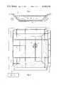
- FIG. 2shows a detailed view of the leak detection system of the present invention from the bottom of the pond in FIG. 1.
- FIG. 3shows an embodiment of the present invention used to detect breaks in a pipeline.
- the present inventionis applicable to, e.g., settling basins, storage basins and tanks, solar ponds, or holding areas for waste streams, as well as to pipelines and other conduit systems.
- a waste disposal pond 10is shown filled with a liquid chemical waste 12.
- the pondis formed by lining an excavated area with an extensive synthetic polymer lining 11.
- a wire networkis positioned beneath the reservoir or conduit in the vicinity of where leaks are likely to occur.
- chemical reservoirs formed by lining an excavated area with an extensive polymer lining in the pasthave been constructed with a bed of sand under the liner which prevents puncture and transmits any leakage to a location at the periphery of the reservoir where it can be collected.
- a networkcomprising two sets of parallel wires is placed in such a sand bed so that the sets of wires are separated from each other by a layer of sand.
- the wires of one setcross the wires of the other at predictable angles and in a prescribed geometric pattern, e.g., at right angles to form a grid pattern as shown in FIG. 2.
- a lining composed of a so-called "geotextile fabric”may be used in place of the sand bed.
- geotextilesare blankets of woven and non-woven fiber materials that are generally formed from polymers such as polyesters and nylons. Situated beneath the plastic liner, these fabrics function much the same way as a sand bed, preventing puncture and draining leakage to a peripheral location for collection.
- a geotextile fabriccan be manufactured to incorporate the wire network, for example by replacing selected spools of the yarn forming the fabric with spools of the network wire.
- the wirescan be separated from one another at the points of intersection by a layer of fabric.
- Geotextile fabricsare porous enough that when leaks occur a change in the electrical properties of the wires will result.
- an entire wire network like that described aboveis woven into a pad of geotextile fabric with the criss-crossing sets of wires separated from each other by fabric within the pad. Since specific wires in the network may be corroded if a leak in the pad occurs, each wire in the network can be connected at both of its ends to separate winding spools or similar devices positioned at the edge of the pad which would permit one to draw the length of wire through the pad, thereby replacing the corroded portion of the wire with new conductor.
- wires in the networkwould pass through a plastic, fabric or other adequately flexible liner, or through a layer of sand, by way of tubes in the liner or sand layer composed of a material sufficiently porous to permit leaking fluid to come into contact with the wire or group of wires within.
- exemplary suitable materials for such tubesare the ceramic compositions utilized in lysimeters, geotextile fibers, and perforated polyvinyl chloride plastics.
- the corroded wirescan be replaced after a leak has occurred and been repaired by splicing new conductor into the network to replace corroded wires. In this manner the system allows more rapid detection, location and monitoring of liner leaks than is currently available.
- Embodiments of the inventionare also envisioned in which the wires are adhered to the plastic liner forming the reservoir using a permeable adhesive composition or tape, or, when the liner is sufficiently thick, the wires are scored into the liner.
- FIG. 2is a detailed view of the leak detection system as seen from the bottom of the pond.
- the wire networkcomprises a metal wire grid 13 positioned directly beneath the liner 11.
- the illustrated wire gridconsists of two criss-crossing sets of parallel wires.
- the first set of parallel wirescomprises wires 31, 32, 33 and 34.
- the second set of parallel wires(31a, 32a, 33a, 34a, 35a and 36a) extends in a direction transverse to the first set of wires so that the two sets cross at predictable angles (here, 90°).
- the wires of the respective gridsare separated from one another, either by soil, fabric or some other insulator, at the points of crossing, the latter being spaced under the pond so as to facilitate the detection and localization of the leak as now described.
- the change in the resistance of wires 33 and 33alocates the leak in the vicinity of their crossing. Also, in accordance with the present invention it is possible to estimate the size of a leak and monitor its progression. For example, in its early stages a leak at 14 might be considered minor and a decision to repair it could be postponed until, for example, the resistances of wires 32a and 34a were also affected.
- FIG. 2illustrates a grid arrangement
- one set of wiresforms a series of concentric circles of successively decreasing diameters and another set extends radially and divides the circles into arcs.
- the wiresare fabricated in a gauge and from a metal that will easily corrode when contacted with the chemicals stored in the reservoir directly above the detection system.
- Aluminum, copper and steel wires about 0.040 inch in diameterhave been studied for use in the invention and it has been found that steel wire easily corrodes upon contact with the leakage from an acid pond, whereas an aluminum wire corrodes particularly quickly in the presence of an alkaline leakage such as sodium hydroxide.
- the systemcan be made more versatile by employing a combination of different wires.
- a system employing steel and aluminum wires togethercould be used to detect leaks of either an acid or an alkaline liquid.
- the wires in one gridmight be alternately acid-corrodable and alkali-corrodable.
- two gridscould be superimposed, one above the other, one grid being acid-corrodable and the other grid alkali-corrodable.
- leaks in the linerare instantly detected as a change in the electrical properties, e.g., the resistance, conductance or impedance, in each wire affected.
- the electrical resistance or voltage across each wire in the networkwould be measured and recorded prior to introducing the waste chemicals or placing the sytem into operation. This is in sharp contrast to the technique disclosed by Berry, whereby the resistance between pairs of wires would be measured.
- the grid arrangement of criss-crossing sets of wiresis a prerequisite to operability of the leak-detection system.
- such a criss-crossing networkis useful with (but not necessary to) the present invention, since the regular geometry of the network permits easy localization of the leak.
- a grid networkneed not be present for applicant's invention to operate as a leak-detector, which function may be fulfilled by a single wire in saturated soil.
- the present inventionis concerned with a change in the electrical properties of the conductors themselves. As a result, the present invention is not subject to problems that occur when the conductivity of the medium surrounding the conductors cannot be controlled.
- the resistance across the wires in the present inventionremains fairly constant or is subject to only predictable and small consistent changes during the service life of the liner. Any natural deterioration in the wires such as due to soil moisture can also be monitored and offset using a small control grid set in the soil adjacent the reservoir.
- the chemicals in the reservoircontact the wires in the grid directly beneath the leak, causing a noticeable change in electrical properties.
- the changemay be caused by corrosion of the wires or, where the chemical waste itself is electrically conductive, result from contact of the waste with the wires.
- the change in electrical propertiescan easily be detected by a variety of conventional means and the exact location of the leak can be determined from the points of intersection of the wires in which a change in resistance is detected.
- One example of the variety of means for monitoring the voltage across the wiresis a Model 2240 B Data Logger by Fluke Co., Tilburg, The Netherlands. In an extreme case, or when a very thin gauge wire is used, the wires can be corroded through producing a break in the circuit.
- the leakage detection system described aboveis used in association with a pipeline or other type of conduit through which potential environmental pollutants are transported.
- An arrangement of this sortis shown in FIG. 3, where an orthogonal network (1) of wires (2) is deployed near a pipeline (3) connecting holding tanks (4) and (5), so that any leakage from the pipeline results in contact between the network and the chemical being transported through the pipeline.
- the electrical properties of one or more wires in the networkare altered, which alteration is detected in each wire affected, thereby permitting the localization of the leakage, as described above.
- the present inventionalso provides an embodiment whereby leaks in reservoirs and conduits containing substantially non-corrosive and non-conductive materials can be detected. Leaks from reservoirs and conduits containing many organic solvents and petroleum products cannot be detected using a simple matrix of uninsulated wires, as described above, because the leaking fluids do not corrode or otherwise affect the conductive properties of the wires.
- the wires used in the systemare coated with a material which can be dissolved or otherwise degraded by the chemicals in the reservoir or conduit. In this case, when a leak occurs, the coating is degraded or removed to such an extent that a change in the electrical properties of each affected wire is detected.
- a first set of parallel wiresmight be coated with, for example, a gum rubber which is degradable by one organic solvent, while the second criss-crossing set of parallel wires would also be coated with the degradable gum rubber.
- the gum rubberWith leakage of the organic solvent, the gum rubber would be attacked by the solvent and degraged to the extent that a change in the conductivity of the partially or fully uncoated wires affected would occur.
- multiple separate pairs of criss-crossing sets of wirescould be employed in a single system, each pair (or each set within a pair) having wires coated with an insulation susceptible to attack by a different non-conducting fluid.
- leaks from a reservoir or conduit carrying different fluids at different timescould be detected.
Landscapes
- Physics & Mathematics (AREA)
- General Physics & Mathematics (AREA)
- Examining Or Testing Airtightness (AREA)
Abstract
Description
Claims (18)
Priority Applications (1)
| Application Number | Priority Date | Filing Date | Title |
|---|---|---|---|
| US06/298,414US4404516A (en) | 1980-10-29 | 1981-09-01 | System for detecting leaks from liquid-containing reservoirs and conduits |
Applications Claiming Priority (2)
| Application Number | Priority Date | Filing Date | Title |
|---|---|---|---|
| US20184180A | 1980-10-29 | 1980-10-29 | |
| US06/298,414US4404516A (en) | 1980-10-29 | 1981-09-01 | System for detecting leaks from liquid-containing reservoirs and conduits |
Related Parent Applications (1)
| Application Number | Title | Priority Date | Filing Date |
|---|---|---|---|
| US20184180AContinuation-In-Part | 1980-10-29 | 1980-10-29 |
Publications (1)
| Publication Number | Publication Date |
|---|---|
| US4404516Atrue US4404516A (en) | 1983-09-13 |
Family
ID=26897139
Family Applications (1)
| Application Number | Title | Priority Date | Filing Date |
|---|---|---|---|
| US06/298,414Expired - LifetimeUS4404516A (en) | 1980-10-29 | 1981-09-01 | System for detecting leaks from liquid-containing reservoirs and conduits |
Country Status (1)
| Country | Link |
|---|---|
| US (1) | US4404516A (en) |
Cited By (67)
| Publication number | Priority date | Publication date | Assignee | Title |
|---|---|---|---|---|
| US4543525A (en)* | 1983-05-09 | 1985-09-24 | Foote Mineral Company | Method for determining a leak in a pond liner of electrically insulating sheet material |
| EP0170174A1 (en)* | 1984-07-20 | 1986-02-05 | W.L. Gore & Associates GmbH | System for detecting leaks of acid or basic products |
| US4598277A (en)* | 1984-07-30 | 1986-07-01 | Chevron Research Company | Water detection subassemblies and method of forming same, for use in computer processing centers |
| US4644263A (en)* | 1984-12-13 | 1987-02-17 | Marathon Oil Company | Method and apparatus for measuring water in crude oil |
| US4684293A (en)* | 1983-03-23 | 1987-08-04 | Nippon Steel Corporation | Cable for fastening structures and method of detecting damage to corrosion-preventive layer thereof |
| US4697456A (en)* | 1986-10-02 | 1987-10-06 | Maser Kenneth R | Leakage test for liquid containment |
| US4710353A (en)* | 1985-07-19 | 1987-12-01 | Junkosha Co., Ltd. | Corrosive liquid leak detecting sensor |
| US4725785A (en)* | 1985-12-17 | 1988-02-16 | Southwest Research Institute | Directional potential analyzer method and apparatus for detecting and locating leaks in geomembrane liners |
| US4823116A (en)* | 1987-11-30 | 1989-04-18 | International Lubrication And Fuel Consultants, Inc. | Fluid detector |
| US4839601A (en)* | 1984-10-24 | 1989-06-13 | Cotterell Daniel E C | Directional current finder |
| EP0325665A1 (en)* | 1988-01-26 | 1989-08-02 | Klaus-Peter Kolbatz | Device for locating liquid in particular water infiltrated into a ceiling |
| US4896528A (en)* | 1987-11-16 | 1990-01-30 | Lewis Donald E | Tank bottom leak testing and apparatus |
| AU599447B2 (en)* | 1986-11-25 | 1990-07-19 | Southwest Research Institute | Method and apparatus for locating leaks in a multiple layer geomembrane |
| US4965554A (en)* | 1987-07-21 | 1990-10-23 | Darling John E | Moisture presence alarm system |
| US4985682A (en)* | 1986-11-20 | 1991-01-15 | Leak Sensors, Inc. | Leak monitor for secondary containment of liquid stored in underground storage tanks |
| EP0418209A1 (en)* | 1989-06-21 | 1991-03-20 | S.A. Uco N.V. | Leak detecting procedure |
| US5015958A (en)* | 1983-06-30 | 1991-05-14 | Raychem Corporation | Elongate sensors comprising conductive polymers, and methods and apparatus using such sensors |
| US5081422A (en)* | 1990-09-07 | 1992-01-14 | Ishiang Shih | Methods for roof, wall or floor leak detection |
| US5120160A (en)* | 1990-03-05 | 1992-06-09 | Environmental Reclamation Systems, Inc. | Method and apparatus for confining and reclaiming hydrocarbon contaminated land sites |
| US5127771A (en)* | 1989-06-13 | 1992-07-07 | Philipp Holzmann Aktiengesellschaft | Narrow or slotted wall which is introduced into a substratum and sealing wall composition contained therein |
| GB2254465A (en)* | 1991-03-20 | 1992-10-07 | Inco Ltd | Conduit liner monitor |
| US5155356A (en)* | 1991-11-29 | 1992-10-13 | Troxler Electronic Laboratories, Inc. | Apparatus and method for detecting subterranean leakage from a large storage vessel |
| US5217304A (en)* | 1991-08-02 | 1993-06-08 | The United States Of America As Represented By The United States Department Of Energy | Electrical network method for the thermal or structural characterization of a conducting material sample or structure |
| US5235286A (en)* | 1985-06-12 | 1993-08-10 | Raychem Corporation | Method for detecting and obtaining information about changers in variables |
| EP0456094A3 (en)* | 1990-05-11 | 1993-08-11 | W.L. Gore & Associates Gmbh | Flat-bottomed container and leak monitoring procedure therefor |
| US5288168A (en)* | 1992-08-24 | 1994-02-22 | Gundle Lining Construction Corporation | Method and apparatus for lining outdoor fluid containment areas to facilitate electrical leak detection |
| US5340238A (en)* | 1992-08-04 | 1994-08-23 | Tanknology Corporation International | Method and apparatus for testing above ground liquid storage tanks for leaks |
| US5357202A (en)* | 1991-12-19 | 1994-10-18 | Henderson Michael E | Plural electrode method for measuring subsurface changes in conductivity as an indication of fluid migration |
| US5382909A (en)* | 1983-06-30 | 1995-01-17 | Raychem Corporation | Method for detecting and obtaining information about changes in variables |
| WO1995021965A1 (en)* | 1994-02-10 | 1995-08-17 | University Of Newcastle Upon Tyne | Improvements relating to geosynthetics |
| DE19534677A1 (en)* | 1994-09-30 | 1996-04-11 | Hubert Reidick | Landfill base seal monitoring appts. |
| WO1996012177A1 (en)* | 1994-10-17 | 1996-04-25 | Henderson Michael E | Detection and location system for monitoring changes in resistivity in three dimensions |
| US5526679A (en)* | 1995-01-05 | 1996-06-18 | Campo/Miller | Automatically calibrated pressurized piping leak detector |
| JPH08178790A (en)* | 1994-12-22 | 1996-07-12 | Riken Kogyo Kk | Waterproofing work structure for construction |
| US5540085A (en)* | 1993-11-30 | 1996-07-30 | Sakata Denki Co., Ltd | Method of measuring leakage position in impervious bottom sheet using electrodes mounted on both surfaces of the sheet and apparatus therefor |
| EP0786655A3 (en)* | 1997-05-07 | 1997-12-10 | Martin Lehmann | Procedure for leak testing of closed containers, test chamber, device and installation therefor |
| WO1998011414A1 (en)* | 1996-09-10 | 1998-03-19 | Progeo Monitoring Gmbh | Device for detecting and locating leakage fluids in sealing systems |
| US5824883A (en)* | 1996-07-16 | 1998-10-20 | Samsung Display Devices Co., Ltd. | Battery leakage sensing system |
| US6056477A (en)* | 1997-07-29 | 2000-05-02 | Taiyo Kogyo Corporation | Waste disposal site |
| US6405135B1 (en) | 2000-07-18 | 2002-06-11 | John J. Adriany | System for remote detection and notification of subterranean pollutants |
| WO2003012484A1 (en) | 2001-07-31 | 2003-02-13 | Terram Limited | Detecting buried geosynthetic |
| US6648552B1 (en)* | 1999-10-14 | 2003-11-18 | Bechtel Bwxt Idaho, Llc | Sensor system for buried waste containment sites |
| US20040046671A1 (en)* | 2002-09-05 | 2004-03-11 | Ninberg Jeffrey A. | Fluid leak detection device |
| DE10256913B3 (en)* | 2002-11-28 | 2004-04-08 | Cta Industriemontage Gmbh | Leakage monitoring device for vertical vessel wall of tank or silo for hazardous liquid detecting leakage liquid in collection space coupled to monitoring space between vessel inner and outer skins |
| US6777947B2 (en) | 2002-04-29 | 2004-08-17 | Tyco Thermal Controls Llc. | Sensor cable |
| US20040162475A1 (en)* | 1998-12-23 | 2004-08-19 | Newcastle University Ventures Limited | Electro kinetic geosynthetic structure |
| KR100467835B1 (en)* | 2001-05-09 | 2005-01-24 | 한국건설기술연구원 | Grid-net contraminant leakage detection system of using method of measuring electrical resistance and measuring method thereof |
| US20060012485A1 (en)* | 2004-07-19 | 2006-01-19 | Tacilauskas Andrew V | Fluid detection apparatus and kit, and method of installation thereof |
| DE10353536B4 (en)* | 2003-11-14 | 2006-07-20 | Cta Industriemontage Gmbh | Device for pressure-free leakage monitoring on vertical vessel walls |
| WO2006117100A1 (en)* | 2005-04-29 | 2006-11-09 | Bernd Lorenz | Leak testing and leak localization arrangement for leak testing and leak localization for flat roofs or the like |
| WO2006114081A3 (en)* | 2005-04-28 | 2007-09-07 | Rossendorf Forschzent | Grid sensor |
| US7951182B2 (en)* | 2005-07-14 | 2011-05-31 | Zoll Circulation, Inc. | System and method for leak detection in external cooling pad |
| CN103328946A (en)* | 2011-08-05 | 2013-09-25 | 俞洪根 | Oil leak detection device |
| WO2013188734A1 (en)* | 2012-06-15 | 2013-12-19 | Pratt & Whitney Rocketdyne, Inc. | Leakage detection |
| US20140049247A1 (en)* | 2012-08-15 | 2014-02-20 | Clark Robert Gunness | Leak detection and location system, method, and software product |
| KR101445310B1 (en) | 2008-12-02 | 2014-09-26 | 유홍근 | Leak Sensing Apparatus |
| FR3007433A1 (en)* | 2013-06-24 | 2014-12-26 | Soletanche Freyssinet | LEAK PREVENTION SYSTEM FOR RETENTION BASIN AND METHOD THEREFOR. |
| US20170096818A1 (en)* | 2015-10-06 | 2017-04-06 | Clark Robert Gunness | Systems and Methods for Leak Detection in Roofing and Waterproofing Membranes |
| US9624671B1 (en)* | 2015-12-03 | 2017-04-18 | Clark Robert Gunness | Leak detection and location system and method |
| US9771703B1 (en) | 2015-04-16 | 2017-09-26 | BuildTech Solutions LLC | Integrated waterproofing and drainage system with intrinsic leak detection |
| JP2017528730A (en)* | 2014-07-01 | 2017-09-28 | センサー・スポレチノスト・エス・ルチェニーム・オブメドゼニームSENSOR spol.s.r.o. | Sensors and systems for monitoring the integrity of waterproof systems or membranes |
| US10344470B2 (en) | 2015-04-16 | 2019-07-09 | BuildTech Solutions LLC | Integrated waterproofing and drainage system with intrinsic leak detection for building structures and methods of use |
| US10488293B1 (en)* | 2018-10-10 | 2019-11-26 | Layfield Group Ltd. | Conductive geotextile |
| US10852225B2 (en)* | 2017-09-01 | 2020-12-01 | Crane Resistoflex | Corrosion indicator for use with a piping system, and a piping system using the corrosion indicator |
| US11105096B2 (en) | 2015-04-16 | 2021-08-31 | BuildTech Solutions LLC | Integrated waterproofing and drainage system with intrinsic leak detection for building structures and methods of use |
| US11614378B2 (en) | 2017-01-06 | 2023-03-28 | Direct-C Limited | Polymeric nanocomposite based sensor and coating systems and their applications |
| US12442192B1 (en)* | 2025-05-16 | 2025-10-14 | Detec Systems Llc | Method of providing a conductive substrate for an electrical leak detection method and a board therefor |
Citations (14)
| Publication number | Priority date | Publication date | Assignee | Title |
|---|---|---|---|---|
| US3197698A (en)* | 1959-12-07 | 1965-07-27 | Pure Oil Co | Temperature-controlled corrosion test probe |
| US3252155A (en)* | 1962-05-18 | 1966-05-17 | American Potash & Chem Corp | Liquid receptacle and method for preparing same |
| US3365661A (en)* | 1965-04-26 | 1968-01-23 | Anaconda Wire & Cable Co | Method and apparatus for locating leaks in a cable by determining the distance to a short circuit in the cable |
| US3383863A (en)* | 1966-08-03 | 1968-05-21 | Joe R. Berry | Pond, tank and pit liner and method of detecting leaks |
| US3564526A (en)* | 1966-12-23 | 1971-02-16 | Butts Ernest Otto | Pipeline leak detection device |
| US3600674A (en)* | 1969-04-02 | 1971-08-17 | Chevron Res | Method of determining leaks from buried pipelines using a time-sharing transmission line |
| US3721898A (en)* | 1968-12-04 | 1973-03-20 | P Dragoumis | Apparatus for detecting leakage from or rupture of pipes and other vessels containing fluid under pressure |
| US3728615A (en)* | 1969-10-29 | 1973-04-17 | Eaton Yale & Towne | Smoke, gas, or rapid temperature increase detector utilizing a periodic electric field to create a self-sustained avalanche current |
| US4095174A (en)* | 1976-01-22 | 1978-06-13 | Towa Electric Co., Ltd. | System for detecting leakage faults in a pipeline by measuring the distributed capacitance of sections of a sensing cable buried parallel to said pipeline |
| US4107672A (en)* | 1975-01-22 | 1978-08-15 | Shell Internationale Research Maatschappij B.V. | Apparatus and method for detecting cracks in the heat-insulating lining of a container for cold liquids |
| US4159447A (en)* | 1976-09-25 | 1979-06-26 | Dr. C. Otto & Comp. G.M.B.H. | System for detecting faults in the wall of a high-temperature pressure vessel |
| FR2425636A1 (en)* | 1978-05-11 | 1979-12-07 | Carbonisation Entr Ceram | Detecting liq. metal leaks along pipes in nuclear reactors - by change in resistance of wires buried in refractory insulating fabric placed around pipe |
| US4206632A (en)* | 1979-01-23 | 1980-06-10 | Hirosuke Suzuki | Liquid detecting device |
| US4305724A (en)* | 1980-08-04 | 1981-12-15 | Delphian Partners | Combustible gas detection system |
- 1981
- 1981-09-01USUS06/298,414patent/US4404516A/ennot_activeExpired - Lifetime
Patent Citations (14)
| Publication number | Priority date | Publication date | Assignee | Title |
|---|---|---|---|---|
| US3197698A (en)* | 1959-12-07 | 1965-07-27 | Pure Oil Co | Temperature-controlled corrosion test probe |
| US3252155A (en)* | 1962-05-18 | 1966-05-17 | American Potash & Chem Corp | Liquid receptacle and method for preparing same |
| US3365661A (en)* | 1965-04-26 | 1968-01-23 | Anaconda Wire & Cable Co | Method and apparatus for locating leaks in a cable by determining the distance to a short circuit in the cable |
| US3383863A (en)* | 1966-08-03 | 1968-05-21 | Joe R. Berry | Pond, tank and pit liner and method of detecting leaks |
| US3564526A (en)* | 1966-12-23 | 1971-02-16 | Butts Ernest Otto | Pipeline leak detection device |
| US3721898A (en)* | 1968-12-04 | 1973-03-20 | P Dragoumis | Apparatus for detecting leakage from or rupture of pipes and other vessels containing fluid under pressure |
| US3600674A (en)* | 1969-04-02 | 1971-08-17 | Chevron Res | Method of determining leaks from buried pipelines using a time-sharing transmission line |
| US3728615A (en)* | 1969-10-29 | 1973-04-17 | Eaton Yale & Towne | Smoke, gas, or rapid temperature increase detector utilizing a periodic electric field to create a self-sustained avalanche current |
| US4107672A (en)* | 1975-01-22 | 1978-08-15 | Shell Internationale Research Maatschappij B.V. | Apparatus and method for detecting cracks in the heat-insulating lining of a container for cold liquids |
| US4095174A (en)* | 1976-01-22 | 1978-06-13 | Towa Electric Co., Ltd. | System for detecting leakage faults in a pipeline by measuring the distributed capacitance of sections of a sensing cable buried parallel to said pipeline |
| US4159447A (en)* | 1976-09-25 | 1979-06-26 | Dr. C. Otto & Comp. G.M.B.H. | System for detecting faults in the wall of a high-temperature pressure vessel |
| FR2425636A1 (en)* | 1978-05-11 | 1979-12-07 | Carbonisation Entr Ceram | Detecting liq. metal leaks along pipes in nuclear reactors - by change in resistance of wires buried in refractory insulating fabric placed around pipe |
| US4206632A (en)* | 1979-01-23 | 1980-06-10 | Hirosuke Suzuki | Liquid detecting device |
| US4305724A (en)* | 1980-08-04 | 1981-12-15 | Delphian Partners | Combustible gas detection system |
Cited By (101)
| Publication number | Priority date | Publication date | Assignee | Title |
|---|---|---|---|---|
| US4684293A (en)* | 1983-03-23 | 1987-08-04 | Nippon Steel Corporation | Cable for fastening structures and method of detecting damage to corrosion-preventive layer thereof |
| US4543525A (en)* | 1983-05-09 | 1985-09-24 | Foote Mineral Company | Method for determining a leak in a pond liner of electrically insulating sheet material |
| US5015958A (en)* | 1983-06-30 | 1991-05-14 | Raychem Corporation | Elongate sensors comprising conductive polymers, and methods and apparatus using such sensors |
| US5382909A (en)* | 1983-06-30 | 1995-01-17 | Raychem Corporation | Method for detecting and obtaining information about changes in variables |
| EP0170174A1 (en)* | 1984-07-20 | 1986-02-05 | W.L. Gore & Associates GmbH | System for detecting leaks of acid or basic products |
| US4598277A (en)* | 1984-07-30 | 1986-07-01 | Chevron Research Company | Water detection subassemblies and method of forming same, for use in computer processing centers |
| US4839601A (en)* | 1984-10-24 | 1989-06-13 | Cotterell Daniel E C | Directional current finder |
| US4644263A (en)* | 1984-12-13 | 1987-02-17 | Marathon Oil Company | Method and apparatus for measuring water in crude oil |
| US5235286A (en)* | 1985-06-12 | 1993-08-10 | Raychem Corporation | Method for detecting and obtaining information about changers in variables |
| US4710353A (en)* | 1985-07-19 | 1987-12-01 | Junkosha Co., Ltd. | Corrosive liquid leak detecting sensor |
| US4725785A (en)* | 1985-12-17 | 1988-02-16 | Southwest Research Institute | Directional potential analyzer method and apparatus for detecting and locating leaks in geomembrane liners |
| US4697456A (en)* | 1986-10-02 | 1987-10-06 | Maser Kenneth R | Leakage test for liquid containment |
| US4985682A (en)* | 1986-11-20 | 1991-01-15 | Leak Sensors, Inc. | Leak monitor for secondary containment of liquid stored in underground storage tanks |
| AU599447B2 (en)* | 1986-11-25 | 1990-07-19 | Southwest Research Institute | Method and apparatus for locating leaks in a multiple layer geomembrane |
| US4965554A (en)* | 1987-07-21 | 1990-10-23 | Darling John E | Moisture presence alarm system |
| US4896528A (en)* | 1987-11-16 | 1990-01-30 | Lewis Donald E | Tank bottom leak testing and apparatus |
| US4823116A (en)* | 1987-11-30 | 1989-04-18 | International Lubrication And Fuel Consultants, Inc. | Fluid detector |
| EP0325665A1 (en)* | 1988-01-26 | 1989-08-02 | Klaus-Peter Kolbatz | Device for locating liquid in particular water infiltrated into a ceiling |
| US5127771A (en)* | 1989-06-13 | 1992-07-07 | Philipp Holzmann Aktiengesellschaft | Narrow or slotted wall which is introduced into a substratum and sealing wall composition contained therein |
| EP0418209A1 (en)* | 1989-06-21 | 1991-03-20 | S.A. Uco N.V. | Leak detecting procedure |
| BE1004301A3 (en)* | 1989-06-21 | 1992-10-27 | Uco Nv Sa | Method for detection of leaks and fixes used geotextiles. |
| US5120160A (en)* | 1990-03-05 | 1992-06-09 | Environmental Reclamation Systems, Inc. | Method and apparatus for confining and reclaiming hydrocarbon contaminated land sites |
| US5269173A (en)* | 1990-05-11 | 1993-12-14 | Klaus Henneck | Flat bottomed tanks and process to detect leakages |
| EP0456094A3 (en)* | 1990-05-11 | 1993-08-11 | W.L. Gore & Associates Gmbh | Flat-bottomed container and leak monitoring procedure therefor |
| US5081422A (en)* | 1990-09-07 | 1992-01-14 | Ishiang Shih | Methods for roof, wall or floor leak detection |
| GB2254465A (en)* | 1991-03-20 | 1992-10-07 | Inco Ltd | Conduit liner monitor |
| US5177468A (en)* | 1991-03-20 | 1993-01-05 | Inco Limited | Conduit liner monitor |
| GB2254465B (en)* | 1991-03-20 | 1994-11-30 | Inco Ltd | Conduit liner monitor |
| US5217304A (en)* | 1991-08-02 | 1993-06-08 | The United States Of America As Represented By The United States Department Of Energy | Electrical network method for the thermal or structural characterization of a conducting material sample or structure |
| EP0545784A3 (en)* | 1991-11-29 | 1993-06-30 | Troxler Electronic Laboratories, Inc. | Apparatus and method for detecting subterranean leakage from a large storage vessel |
| US5155356A (en)* | 1991-11-29 | 1992-10-13 | Troxler Electronic Laboratories, Inc. | Apparatus and method for detecting subterranean leakage from a large storage vessel |
| US5357202A (en)* | 1991-12-19 | 1994-10-18 | Henderson Michael E | Plural electrode method for measuring subsurface changes in conductivity as an indication of fluid migration |
| US5340238A (en)* | 1992-08-04 | 1994-08-23 | Tanknology Corporation International | Method and apparatus for testing above ground liquid storage tanks for leaks |
| US5288168A (en)* | 1992-08-24 | 1994-02-22 | Gundle Lining Construction Corporation | Method and apparatus for lining outdoor fluid containment areas to facilitate electrical leak detection |
| US5540085A (en)* | 1993-11-30 | 1996-07-30 | Sakata Denki Co., Ltd | Method of measuring leakage position in impervious bottom sheet using electrodes mounted on both surfaces of the sheet and apparatus therefor |
| WO1995021965A1 (en)* | 1994-02-10 | 1995-08-17 | University Of Newcastle Upon Tyne | Improvements relating to geosynthetics |
| GB2301311B (en)* | 1994-02-10 | 1998-06-10 | Univ Newcastle | Improvements relating to geosynthetics |
| US5980155A (en)* | 1994-02-10 | 1999-11-09 | University Of Newcastle Upon Tyne | Composite geosynthetics and methods for their use |
| GB2301311A (en)* | 1994-02-10 | 1996-12-04 | Univ Newcastle | Improvements relating to geosynthetics |
| DE19534677A1 (en)* | 1994-09-30 | 1996-04-11 | Hubert Reidick | Landfill base seal monitoring appts. |
| DE19534677C2 (en)* | 1994-09-30 | 1998-04-09 | Hubert Reidick | Device for monitoring sealing soil formations, in particular landfill base seals |
| US5537045A (en)* | 1994-10-17 | 1996-07-16 | Henderson; Michael E. | Detection and location system for monitoring changes in resistivity in three dimensions |
| WO1996012177A1 (en)* | 1994-10-17 | 1996-04-25 | Henderson Michael E | Detection and location system for monitoring changes in resistivity in three dimensions |
| JPH08178790A (en)* | 1994-12-22 | 1996-07-12 | Riken Kogyo Kk | Waterproofing work structure for construction |
| US5883301A (en)* | 1995-01-05 | 1999-03-16 | Campo/Miller | Method and apparatus for calibrating a leak detector |
| US5526679A (en)* | 1995-01-05 | 1996-06-18 | Campo/Miller | Automatically calibrated pressurized piping leak detector |
| US5824883A (en)* | 1996-07-16 | 1998-10-20 | Samsung Display Devices Co., Ltd. | Battery leakage sensing system |
| WO1998011414A1 (en)* | 1996-09-10 | 1998-03-19 | Progeo Monitoring Gmbh | Device for detecting and locating leakage fluids in sealing systems |
| US5962776A (en)* | 1997-05-07 | 1999-10-05 | Lehmann; Martin | Method for tightness testing of closed vessels, test chamber tester and testing system therefor |
| WO1998050769A1 (en)* | 1997-05-07 | 1998-11-12 | Martin Lehmann | Leak test for closed receptacles, testing chamber, testing device and installation therefor |
| EP0786655A3 (en)* | 1997-05-07 | 1997-12-10 | Martin Lehmann | Procedure for leak testing of closed containers, test chamber, device and installation therefor |
| KR100786763B1 (en) | 1997-05-07 | 2007-12-18 | 마틴 레흐만 | Method for producing unleaky liquid content-filled container |
| US6185987B1 (en) | 1997-05-07 | 2001-02-13 | Martin Lehmann | Method for tightness testing of closed containers, test chamber, test system, and tester therefor |
| AU738753B2 (en)* | 1997-05-07 | 2001-09-27 | Wilco Ag | Leak test process for closed receptacles, test chamber, test set-up and testing device for this process |
| CN1322319C (en)* | 1997-05-07 | 2007-06-20 | 马丁·莱曼 | Method for checking the tightness of a closed container, inspection chamber, inspection device and inspection device therefor |
| RU2213333C2 (en)* | 1997-05-07 | 2003-09-27 | Мартин Леманн | Method testing closed vessels for tightness, testing chamber, testing facility and testing plant for realization of method |
| US6056477A (en)* | 1997-07-29 | 2000-05-02 | Taiyo Kogyo Corporation | Waste disposal site |
| US7150583B2 (en) | 1998-12-23 | 2006-12-19 | Newcastle University Ventures Limited | Electro kinetic geosynthetic structure |
| US20040162475A1 (en)* | 1998-12-23 | 2004-08-19 | Newcastle University Ventures Limited | Electro kinetic geosynthetic structure |
| US6648552B1 (en)* | 1999-10-14 | 2003-11-18 | Bechtel Bwxt Idaho, Llc | Sensor system for buried waste containment sites |
| US20040064979A1 (en)* | 1999-10-14 | 2004-04-08 | Smith Ann Marie | Sensor system for buried waste containment sites |
| US6948882B2 (en) | 1999-10-14 | 2005-09-27 | Battelle Energy Alliance, Llc | Sensor system for buried waste containment sites |
| US20050271474A1 (en)* | 1999-10-14 | 2005-12-08 | Smith Ann M | Sensor system for buried waste containment sites |
| US6405135B1 (en) | 2000-07-18 | 2002-06-11 | John J. Adriany | System for remote detection and notification of subterranean pollutants |
| KR100467835B1 (en)* | 2001-05-09 | 2005-01-24 | 한국건설기술연구원 | Grid-net contraminant leakage detection system of using method of measuring electrical resistance and measuring method thereof |
| WO2003012484A1 (en) | 2001-07-31 | 2003-02-13 | Terram Limited | Detecting buried geosynthetic |
| US6777947B2 (en) | 2002-04-29 | 2004-08-17 | Tyco Thermal Controls Llc. | Sensor cable |
| US7084777B2 (en)* | 2002-09-05 | 2006-08-01 | Ninberg Jeffrey A | Fluid leak detection device |
| US20040046671A1 (en)* | 2002-09-05 | 2004-03-11 | Ninberg Jeffrey A. | Fluid leak detection device |
| DE10256913B3 (en)* | 2002-11-28 | 2004-04-08 | Cta Industriemontage Gmbh | Leakage monitoring device for vertical vessel wall of tank or silo for hazardous liquid detecting leakage liquid in collection space coupled to monitoring space between vessel inner and outer skins |
| DE10353536B4 (en)* | 2003-11-14 | 2006-07-20 | Cta Industriemontage Gmbh | Device for pressure-free leakage monitoring on vertical vessel walls |
| WO2006007719A1 (en)* | 2004-07-19 | 2006-01-26 | Andrew Victor Tacilauskas | Fluid detection apparatus and kit, and method of installation thereof |
| US7084776B2 (en) | 2004-07-19 | 2006-08-01 | Andrew Victor Tacilauskas | Fluid detection apparatus and kit, and method of installation thereof |
| US20060012485A1 (en)* | 2004-07-19 | 2006-01-19 | Tacilauskas Andrew V | Fluid detection apparatus and kit, and method of installation thereof |
| WO2006114081A3 (en)* | 2005-04-28 | 2007-09-07 | Rossendorf Forschzent | Grid sensor |
| US20080278184A1 (en)* | 2005-04-28 | 2008-11-13 | Heiko Pietruske | Grid Sensor |
| US7795883B2 (en) | 2005-04-28 | 2010-09-14 | Forschungszentrum Dresden - Rossendorf E.V. | Grid sensor |
| US20080143349A1 (en)* | 2005-04-29 | 2008-06-19 | Bernd Lorenz | Leak Testing and Leak Localization Arrangement For Leak Testing and Leak Localization For Flat Roofs or the Like |
| US7872479B2 (en)* | 2005-04-29 | 2011-01-18 | Bernd Lorenz | Leak testing and leak localization arrangement for leak testing and leak localization for flat roofs or the like |
| WO2006117100A1 (en)* | 2005-04-29 | 2006-11-09 | Bernd Lorenz | Leak testing and leak localization arrangement for leak testing and leak localization for flat roofs or the like |
| US7951182B2 (en)* | 2005-07-14 | 2011-05-31 | Zoll Circulation, Inc. | System and method for leak detection in external cooling pad |
| KR101445310B1 (en) | 2008-12-02 | 2014-09-26 | 유홍근 | Leak Sensing Apparatus |
| CN103328946A (en)* | 2011-08-05 | 2013-09-25 | 俞洪根 | Oil leak detection device |
| WO2013188734A1 (en)* | 2012-06-15 | 2013-12-19 | Pratt & Whitney Rocketdyne, Inc. | Leakage detection |
| US9341540B2 (en)* | 2012-08-15 | 2016-05-17 | Clark Robert Gunness | Leak detection and location system, method, and software product |
| US20140049247A1 (en)* | 2012-08-15 | 2014-02-20 | Clark Robert Gunness | Leak detection and location system, method, and software product |
| EP2818603A1 (en)* | 2013-06-24 | 2014-12-31 | Soletanche Freyssinet | Leakage prevention system for a retention pond and related method |
| FR3007433A1 (en)* | 2013-06-24 | 2014-12-26 | Soletanche Freyssinet | LEAK PREVENTION SYSTEM FOR RETENTION BASIN AND METHOD THEREFOR. |
| JP2017528730A (en)* | 2014-07-01 | 2017-09-28 | センサー・スポレチノスト・エス・ルチェニーム・オブメドゼニームSENSOR spol.s.r.o. | Sensors and systems for monitoring the integrity of waterproof systems or membranes |
| US9771703B1 (en) | 2015-04-16 | 2017-09-26 | BuildTech Solutions LLC | Integrated waterproofing and drainage system with intrinsic leak detection |
| US11105096B2 (en) | 2015-04-16 | 2021-08-31 | BuildTech Solutions LLC | Integrated waterproofing and drainage system with intrinsic leak detection for building structures and methods of use |
| US10344470B2 (en) | 2015-04-16 | 2019-07-09 | BuildTech Solutions LLC | Integrated waterproofing and drainage system with intrinsic leak detection for building structures and methods of use |
| US20170097276A1 (en)* | 2015-10-06 | 2017-04-06 | Clark Robert Gunness | Systems and Methods for Leak Detection in Roofing and Waterproofing Membranes |
| US9632003B1 (en)* | 2015-10-06 | 2017-04-25 | Clark Robert Gunness | Systems and methods for leak detection in roofing and waterproofing membranes |
| US9624672B1 (en)* | 2015-10-06 | 2017-04-18 | Clark Robert Gunness | Systems and methods for leak detection in roofing and waterproofing membranes |
| US20170096818A1 (en)* | 2015-10-06 | 2017-04-06 | Clark Robert Gunness | Systems and Methods for Leak Detection in Roofing and Waterproofing Membranes |
| US9624671B1 (en)* | 2015-12-03 | 2017-04-18 | Clark Robert Gunness | Leak detection and location system and method |
| US11614378B2 (en) | 2017-01-06 | 2023-03-28 | Direct-C Limited | Polymeric nanocomposite based sensor and coating systems and their applications |
| US10852225B2 (en)* | 2017-09-01 | 2020-12-01 | Crane Resistoflex | Corrosion indicator for use with a piping system, and a piping system using the corrosion indicator |
| US10488293B1 (en)* | 2018-10-10 | 2019-11-26 | Layfield Group Ltd. | Conductive geotextile |
| US12442192B1 (en)* | 2025-05-16 | 2025-10-14 | Detec Systems Llc | Method of providing a conductive substrate for an electrical leak detection method and a board therefor |
Similar Documents
| Publication | Publication Date | Title |
|---|---|---|
| US4404516A (en) | System for detecting leaks from liquid-containing reservoirs and conduits | |
| US5176025A (en) | Pipeline secondary containment system and method | |
| US5404104A (en) | Device and method for monitoring and locating defects in, and detachment of, the protective covering of underground or immersed metal structures or pipelines | |
| US5378991A (en) | Detecting degradation of non-conductive inert wall layers in fluid containers | |
| US4672366A (en) | Subterranean tank leak containment and detection system | |
| CN109900744B (en) | Seepage analysis system for geomembrane | |
| CA2098333C (en) | Cathodic protection and leak detection process and apparatus | |
| JP2655232B2 (en) | Method for lining an outdoor storage place by facilitating leakage detection and liner | |
| US5357202A (en) | Plural electrode method for measuring subsurface changes in conductivity as an indication of fluid migration | |
| US4673926A (en) | Liquid containment and leak detection system | |
| US5583283A (en) | Impoundment leak detection, location, and containment system | |
| JPH04311584A (en) | Method and device for monitoring accidental damage of protective coating of underground or immersed metallic structure | |
| US3470340A (en) | Leak detection apparatus | |
| US4771246A (en) | Method for determining the location of a leak in a pond liner formed of electrically insulating material | |
| CA1200874A (en) | Leak detection system for subterranean pipelines | |
| CA1316579C (en) | Subterranean tank leak containment and detection system and method | |
| JP4494920B2 (en) | Structure deterioration detection system | |
| Harris et al. | Reducing the Risk of Ground Water Contamination by Improving Petroleum Product Storage | |
| JPH0933382A (en) | Method for detecting leakage position | |
| Allen | A Coating Evaluation Testing Program | |
| Crowther et al. | Smart membranes and pipe monitoring networks; waterproofing and real-time leak detection systems | |
| JP3116796B2 (en) | Detecting method of defective part of impermeable sheet | |
| CN110132649B (en) | A sampling system for groundwater environmental investigation at contaminated sites | |
| Oh et al. | Laboratory tests for the development of contaminant leakage detection system in soil | |
| Anderson et al. | Service Life Prediction Of Fiberglass Reinforced Plastics Corrosion Resistant Equipment |
Legal Events
| Date | Code | Title | Description |
|---|---|---|---|
| STCF | Information on status: patent grant | Free format text:PATENTED CASE | |
| MAFP | Maintenance fee payment | Free format text:PAYMENT OF MAINTENANCE FEE, 4TH YEAR, PL 96-517 (ORIGINAL EVENT CODE: M170); ENTITY STATUS OF PATENT OWNER: SMALL ENTITY Year of fee payment:4 | |
| FEPP | Fee payment procedure | Free format text:PAYOR NUMBER ASSIGNED (ORIGINAL EVENT CODE: ASPN); ENTITY STATUS OF PATENT OWNER: SMALL ENTITY | |
| FEPP | Fee payment procedure | Free format text:MAINTENANCE FEE REMINDER MAILED (ORIGINAL EVENT CODE: REM.); ENTITY STATUS OF PATENT OWNER: SMALL ENTITY | |
| FEPP | Fee payment procedure | Free format text:SURCHARGE FOR LATE PAYMENT, PL 96-517 (ORIGINAL EVENT CODE: M176); ENTITY STATUS OF PATENT OWNER: SMALL ENTITY | |
| MAFP | Maintenance fee payment | Free format text:PAYMENT OF MAINTENANCE FEE, 8TH YEAR, PL 96-517 (ORIGINAL EVENT CODE: M171); ENTITY STATUS OF PATENT OWNER: SMALL ENTITY Year of fee payment:8 | |
| MAFP | Maintenance fee payment | Free format text:PAYMENT OF MAINTENANCE FEE, 12TH YR, SMALL ENTITY (ORIGINAL EVENT CODE: M285); ENTITY STATUS OF PATENT OWNER: SMALL ENTITY Year of fee payment:12 | |
| FEPP | Fee payment procedure | Free format text:PAYOR NUMBER ASSIGNED (ORIGINAL EVENT CODE: ASPN); ENTITY STATUS OF PATENT OWNER: SMALL ENTITY Free format text:PAYER NUMBER DE-ASSIGNED (ORIGINAL EVENT CODE: RMPN); ENTITY STATUS OF PATENT OWNER: SMALL ENTITY |