US4403826A - Ultraviolet radiation detector - Google Patents
Ultraviolet radiation detectorDownload PDFInfo
- Publication number
- US4403826A US4403826AUS06/246,699US24669981AUS4403826AUS 4403826 AUS4403826 AUS 4403826AUS 24669981 AUS24669981 AUS 24669981AUS 4403826 AUS4403826 AUS 4403826A
- Authority
- US
- United States
- Prior art keywords
- sensor
- fiber
- detector
- length
- optical fiber
- Prior art date
- Legal status (The legal status is an assumption and is not a legal conclusion. Google has not performed a legal analysis and makes no representation as to the accuracy of the status listed.)
- Expired - Lifetime
Links
Images
Classifications
- G—PHYSICS
- G01—MEASURING; TESTING
- G01J—MEASUREMENT OF INTENSITY, VELOCITY, SPECTRAL CONTENT, POLARISATION, PHASE OR PULSE CHARACTERISTICS OF INFRARED, VISIBLE OR ULTRAVIOLET LIGHT; COLORIMETRY; RADIATION PYROMETRY
- G01J1/00—Photometry, e.g. photographic exposure meter
- G01J1/58—Photometry, e.g. photographic exposure meter using luminescence generated by light
Definitions
- This inventionrelates to ultraviolet radiation detectors.
- the index-modifying dopantsused to grade the index profile of an optical fiber, fluoresce when exposed to ultraviolet radiation. This phenomenon is then employed as a means for measuring the index profile of fibers and fiber preforms.
- a uv detectorin accordance with the present invention comprises a uv sensor, a visible light (v1) detector, and an optical fiber for coupling between the uv sensor and the v1 detector.
- the sensorcomprises a filamentary host member in which there is embedded a dopant that fluoresces at the uv wavelength of interest.
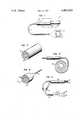
- FIG. 1shows an ultraviolet radiation detector in accordance with the invention
- FIG. 2shows the structural details of the uv sensor
- FIGS. 3, 4 and 5show illustrative sensor configurations.
- FIG. 1shows a uv detecting system in accordance with the present invention comprising a uv sensor 10, a visible light (v1) detector 11, and a length of optical fiber 12 for coupling between the sensor and detector.
- Sensor 10comprises a filamentary member 13 of length L.
- Member 13is made of a material that fluoresces upon exposure to ultraviolet radiation (i.e., between 1500 A and 3250 A) at the wavelength of interest.
- member 13is a length of optical fiber comprising a fluid or solid core region 20 surrounded by a cladding 21 of lower refractive index, as illustrated in FIG. 2.
- the core regionis formed by the addition of a suitable index-modifying dopant, such as germanium, to a host material, such as silica.
- a variety of sensorscan be fabricated using a variety of different dopants and fluids to cover the uv wavelength range of interest.
- the concentration of the index-modifying dopantis advantageously high so as to provide the greatest possible fluorescent emission.
- the induced fluorescencevaries as a linear function of the incident uv. Accordingly, the greater the dopant concentration, the greater the intensity of the resulting visible light.
- the sensoris calibrated for different exposure lengths at the wavelength of interest.
- the effective lengthis determined by means of an adjustable opaque sleeve 14 which can be moved longitudinally along member 13 as indicated by the double-headed arrow 15, to expose varying amounts of the member.
- the fluorescence induced in member 13is coupled to detector 11 by means of a length of conventional optical fiber 12.
- the sensor 13can be a portion of the connecting fiber 12.
- the detectoritself can be any well-known device responsive to light in the visible range. For purposes of illustration, a photodiode 16 and meter 17 are shown.
- the principal advantage of the above-described fiber sensoris its small size which makes it possible to make very fine measurements. For example, some uv sources have irregular radiation patterns which are obviously undesirable if one requires uniform illumination. Using a small sensor makes it possible to obtain an accurate measurement of the radiation pattern.
- FIG. 3shows a sensor configuration wherein the fiber 30 is wound into a spiral for increased sensitivity.
- the fiber 30is wound into a spiral for increased sensitivity.
- other sensor configurationscan readily be devised to conform to unique situations. Because of its small cross-section, the overall size of the sensor can still be kept smaller than conventional uv sensors notwithstanding the length of the fiber employed.
- FIG. 4shows a sensor 40 which tapers from a maximum diameter at the end exposed to the uv to a mininum diameter at the end coupled to the connecting fiber 41.
- a small lens(not shown) can be included to focus the uv radiation onto the core region 42 of the sensor.
Landscapes
- Physics & Mathematics (AREA)
- General Physics & Mathematics (AREA)
- Spectroscopy & Molecular Physics (AREA)
- Investigating, Analyzing Materials By Fluorescence Or Luminescence (AREA)
Abstract
Description
Claims (6)
Priority Applications (1)
| Application Number | Priority Date | Filing Date | Title |
|---|---|---|---|
| US06/246,699US4403826A (en) | 1981-03-23 | 1981-03-23 | Ultraviolet radiation detector |
Applications Claiming Priority (1)
| Application Number | Priority Date | Filing Date | Title |
|---|---|---|---|
| US06/246,699US4403826A (en) | 1981-03-23 | 1981-03-23 | Ultraviolet radiation detector |
Publications (1)
| Publication Number | Publication Date |
|---|---|
| US4403826Atrue US4403826A (en) | 1983-09-13 |
Family
ID=22931828
Family Applications (1)
| Application Number | Title | Priority Date | Filing Date |
|---|---|---|---|
| US06/246,699Expired - LifetimeUS4403826A (en) | 1981-03-23 | 1981-03-23 | Ultraviolet radiation detector |
Country Status (1)
| Country | Link |
|---|---|
| US (1) | US4403826A (en) |
Cited By (41)
| Publication number | Priority date | Publication date | Assignee | Title |
|---|---|---|---|---|
| EP0115025A3 (en)* | 1982-12-23 | 1984-12-12 | Wolfgang Dr. Ruhrmann | Optical sensor |
| US4504114A (en)* | 1982-05-10 | 1985-03-12 | Raychem Corporation | Method of transmitting UV light through optical fibers |
| US4560248A (en)* | 1981-08-14 | 1985-12-24 | Imperial Chemical Industries, Plc | Fibre optic sensor with bonded dye |
| US4627284A (en)* | 1985-07-22 | 1986-12-09 | Spectral Sciences, Inc. | Ultraviolet absorption hygrometer |
| JPS6249244A (en)* | 1985-07-31 | 1987-03-03 | コ−ニング グラス ワ−クス | Spectral spectoscopic analysis method and device |
| US4727247A (en)* | 1985-12-20 | 1988-02-23 | Rosemount Limited | Light attenuation sensing apparatus for measuring physical parameters and other variables utilizing a light conducting member containing a fluorescent material |
| US4753512A (en)* | 1984-12-10 | 1988-06-28 | Commissariat A L'energie Atomique | Process for utilizing light radiation with the aid of fluorescent optical fibres and functional devices and apparatus using said process |
| FR2609778A1 (en)* | 1987-01-16 | 1988-07-22 | Thomson Csf | COLD LIGHT SOURCE WITH HIGH LUMINANCE AND USE FOR IMAGE VISUALIZATION DEVICE |
| WO1988006279A1 (en)* | 1987-02-11 | 1988-08-25 | The Secretary Of State For Defence In Her Britanni | Ultraviolet radiation detector |
| US4782234A (en)* | 1985-05-23 | 1988-11-01 | Tufts University | Method and apparatus for subsurface contaminant detection and measurement |
| FR2616535A1 (en)* | 1987-06-15 | 1988-12-16 | Seftim Sa | Device for detecting sparking and light flashes |
| US4812013A (en)* | 1984-12-10 | 1989-03-14 | Claude Aurouet | Process for utilizing light radiation with the aid of fluorescent optical fibres and functional devices and apparatus using said process |
| EP0334533A3 (en)* | 1988-03-15 | 1989-11-29 | Focal Technologies Incorporated | Fibre optic discrete or continuous liquid level sensor |
| US4885471A (en)* | 1988-04-22 | 1989-12-05 | Taunton Technologies, Inc. | Ultraviolet radiometer |
| US4904876A (en)* | 1987-05-02 | 1990-02-27 | Thomas Swan & Co., Ltd. | Detection of ultraviolet radiation |
| FR2640386A1 (en)* | 1988-12-09 | 1990-06-15 | Alsthom Gec | Device for the detection of light-emitting corona discharges in an enclosed space |
| US4942306A (en)* | 1988-12-30 | 1990-07-17 | Focal Technologies Incorporated | Fibre optic sensor for the continuous measurement liquids level and other parameters |
| US5015067A (en)* | 1988-01-15 | 1991-05-14 | Acculase, Inc. | Optical fiber power output measuring means |
| US5042980A (en)* | 1989-05-26 | 1991-08-27 | C. R. Bard, Inc. | Optical fiber diffusion tip for uniform illumination |
| FR2664381A1 (en)* | 1990-07-04 | 1992-01-10 | Pioneer Electronic Corp | DEVICE FOR DETECTING ULTRAVIOLET RAYS. |
| US5191393A (en)* | 1988-12-05 | 1993-03-02 | Micro-Controle | Optical measurement device and method |
| WO1993007469A1 (en)* | 1991-10-03 | 1993-04-15 | Foster-Miller, Inc. | Optical fiber for spectroscopic monitoring |
| US5207669A (en)* | 1989-05-26 | 1993-05-04 | C. R. Bard, Inc. | Optical fiber diffusion tip for uniform illumination |
| US5585634A (en)* | 1994-09-29 | 1996-12-17 | Foster-Miller, Inc. | Attenuated total reflectance sensing |
| US5712934A (en)* | 1996-07-25 | 1998-01-27 | Johnson; Douglas M. | Fiber optic infrared sensor |
| WO1999037978A1 (en)* | 1998-01-27 | 1999-07-29 | Povl Kaas | A device for intensity measurement of uv light from a lamp and a uv-treatment plant equipped with such a device |
| US6211524B1 (en) | 1997-04-18 | 2001-04-03 | The United States Of America As Represented By The United States Department Of Energy | Enhanced radiation detectors using luminescent materials |
| US6429438B1 (en) | 1999-07-12 | 2002-08-06 | Waterhealth International, Inc. | Ultraviolet light detector for liquid disinfection unit |
| US6965709B1 (en)* | 2003-05-14 | 2005-11-15 | Sandia Corporation | Fluorescent optical position sensor |
| US7049622B1 (en) | 2004-04-09 | 2006-05-23 | Sandia Corporation | Optical position sensor for determining the interface between a clear and an opaque fluid |
| US20070231194A1 (en)* | 2006-03-31 | 2007-10-04 | Searete Llc, A Limited Liability Corporation Of The State Of Delaware | Methods and systems for sterilization |
| US20070231190A1 (en)* | 2006-03-31 | 2007-10-04 | Searete Llc, A Limited Liability Corporation Of The State Of Delaware | Surveying sterilizer methods and systems |
| US20100196214A1 (en)* | 2009-02-05 | 2010-08-05 | Eugene Graff | Air purifying luminaire |
| US8114342B2 (en) | 2006-03-31 | 2012-02-14 | The Invention Science Fund I, Llc | Methods and systems for monitoring sterilization status |
| US8277724B2 (en) | 2006-03-31 | 2012-10-02 | The Invention Science Fund I, Llc | Sterilization methods and systems |
| US8758679B2 (en) | 2006-03-31 | 2014-06-24 | The Invention Science Fund I, Llc | Surveying sterilizer methods and systems |
| US20140275776A1 (en)* | 2013-03-15 | 2014-09-18 | Banpil Photonics, Inc. | Image detecting capsule device and manufacturing thereof |
| US8932535B2 (en) | 2006-03-31 | 2015-01-13 | The Invention Science Fund I, Llc | Surveying sterilizer methods and systems |
| US8992837B2 (en) | 2006-03-31 | 2015-03-31 | The Invention Science Fund I, Llc | Methods and systems for monitoring sterilization status |
| CN113237545A (en)* | 2021-05-18 | 2021-08-10 | 贵州电网有限责任公司 | Optical power detection pen free of carrying tail fiber |
| US20220130621A1 (en)* | 2019-02-11 | 2022-04-28 | Rensselaer Polytechnic Institute | Hybrid fiber for detection of uv light |
Citations (6)
| Publication number | Priority date | Publication date | Assignee | Title |
|---|---|---|---|---|
| US3546460A (en)* | 1967-10-16 | 1970-12-08 | Hartman Systems Co Inc | Nonreciprocal radiation filter device having fluorescent material for wavelength conversion |
| US3935119A (en)* | 1971-11-30 | 1976-01-27 | Owens-Illinois, Inc. | Luminescent device, process, composition, and article |
| US4061922A (en)* | 1976-05-17 | 1977-12-06 | John S. Ewald | Ultraviolet sensing device |
| US4161656A (en)* | 1978-03-28 | 1979-07-17 | Bell Telephone Laboratories, Incorporated | Methods for measuring dopant concentrations in optical fibers and preforms |
| US4243299A (en)* | 1977-09-14 | 1981-01-06 | Jenaer Glaswerk Schott & Gen. | Optical fibers for communication transmission having high stability to nuclear radiation |
| US4257676A (en)* | 1978-08-02 | 1981-03-24 | Siemens Aktiengesellschaft | Device for collecting light |
- 1981
- 1981-03-23USUS06/246,699patent/US4403826A/ennot_activeExpired - Lifetime
Patent Citations (6)
| Publication number | Priority date | Publication date | Assignee | Title |
|---|---|---|---|---|
| US3546460A (en)* | 1967-10-16 | 1970-12-08 | Hartman Systems Co Inc | Nonreciprocal radiation filter device having fluorescent material for wavelength conversion |
| US3935119A (en)* | 1971-11-30 | 1976-01-27 | Owens-Illinois, Inc. | Luminescent device, process, composition, and article |
| US4061922A (en)* | 1976-05-17 | 1977-12-06 | John S. Ewald | Ultraviolet sensing device |
| US4243299A (en)* | 1977-09-14 | 1981-01-06 | Jenaer Glaswerk Schott & Gen. | Optical fibers for communication transmission having high stability to nuclear radiation |
| US4161656A (en)* | 1978-03-28 | 1979-07-17 | Bell Telephone Laboratories, Incorporated | Methods for measuring dopant concentrations in optical fibers and preforms |
| US4257676A (en)* | 1978-08-02 | 1981-03-24 | Siemens Aktiengesellschaft | Device for collecting light |
Non-Patent Citations (1)
| Title |
|---|
| Proceedings of the IEEE, vol. 68(10) Oct. 1980, pp. 1236-1240, "Fiber Transmission Losses in High-Radiation Fields," by George H. Sigel, Jr.* |
Cited By (57)
| Publication number | Priority date | Publication date | Assignee | Title |
|---|---|---|---|---|
| US4560248A (en)* | 1981-08-14 | 1985-12-24 | Imperial Chemical Industries, Plc | Fibre optic sensor with bonded dye |
| US4504114A (en)* | 1982-05-10 | 1985-03-12 | Raychem Corporation | Method of transmitting UV light through optical fibers |
| EP0115025A3 (en)* | 1982-12-23 | 1984-12-12 | Wolfgang Dr. Ruhrmann | Optical sensor |
| US4812013A (en)* | 1984-12-10 | 1989-03-14 | Claude Aurouet | Process for utilizing light radiation with the aid of fluorescent optical fibres and functional devices and apparatus using said process |
| US4753512A (en)* | 1984-12-10 | 1988-06-28 | Commissariat A L'energie Atomique | Process for utilizing light radiation with the aid of fluorescent optical fibres and functional devices and apparatus using said process |
| US4782234A (en)* | 1985-05-23 | 1988-11-01 | Tufts University | Method and apparatus for subsurface contaminant detection and measurement |
| US4627284A (en)* | 1985-07-22 | 1986-12-09 | Spectral Sciences, Inc. | Ultraviolet absorption hygrometer |
| EP0211587A3 (en)* | 1985-07-31 | 1989-03-22 | Corning Glass Works | Dielectric waveguide for use in an assay |
| JPS6249244A (en)* | 1985-07-31 | 1987-03-03 | コ−ニング グラス ワ−クス | Spectral spectoscopic analysis method and device |
| US4727247A (en)* | 1985-12-20 | 1988-02-23 | Rosemount Limited | Light attenuation sensing apparatus for measuring physical parameters and other variables utilizing a light conducting member containing a fluorescent material |
| FR2609778A1 (en)* | 1987-01-16 | 1988-07-22 | Thomson Csf | COLD LIGHT SOURCE WITH HIGH LUMINANCE AND USE FOR IMAGE VISUALIZATION DEVICE |
| EP0280584A1 (en)* | 1987-01-16 | 1988-08-31 | Thomson-Csf | Highly luminous cold light source and its use in an imaging device |
| WO1988006279A1 (en)* | 1987-02-11 | 1988-08-25 | The Secretary Of State For Defence In Her Britanni | Ultraviolet radiation detector |
| US4904876A (en)* | 1987-05-02 | 1990-02-27 | Thomas Swan & Co., Ltd. | Detection of ultraviolet radiation |
| FR2616535A1 (en)* | 1987-06-15 | 1988-12-16 | Seftim Sa | Device for detecting sparking and light flashes |
| US5015067A (en)* | 1988-01-15 | 1991-05-14 | Acculase, Inc. | Optical fiber power output measuring means |
| EP0334533A3 (en)* | 1988-03-15 | 1989-11-29 | Focal Technologies Incorporated | Fibre optic discrete or continuous liquid level sensor |
| US4885471A (en)* | 1988-04-22 | 1989-12-05 | Taunton Technologies, Inc. | Ultraviolet radiometer |
| US5191393A (en)* | 1988-12-05 | 1993-03-02 | Micro-Controle | Optical measurement device and method |
| FR2640386A1 (en)* | 1988-12-09 | 1990-06-15 | Alsthom Gec | Device for the detection of light-emitting corona discharges in an enclosed space |
| US4942306A (en)* | 1988-12-30 | 1990-07-17 | Focal Technologies Incorporated | Fibre optic sensor for the continuous measurement liquids level and other parameters |
| US5042980A (en)* | 1989-05-26 | 1991-08-27 | C. R. Bard, Inc. | Optical fiber diffusion tip for uniform illumination |
| US5207669A (en)* | 1989-05-26 | 1993-05-04 | C. R. Bard, Inc. | Optical fiber diffusion tip for uniform illumination |
| FR2664381A1 (en)* | 1990-07-04 | 1992-01-10 | Pioneer Electronic Corp | DEVICE FOR DETECTING ULTRAVIOLET RAYS. |
| WO1993007469A1 (en)* | 1991-10-03 | 1993-04-15 | Foster-Miller, Inc. | Optical fiber for spectroscopic monitoring |
| US5239176A (en)* | 1991-10-03 | 1993-08-24 | Foster-Miller, Inc. | Tapered optical fiber sensing attenuated total reflectance |
| US5585634A (en)* | 1994-09-29 | 1996-12-17 | Foster-Miller, Inc. | Attenuated total reflectance sensing |
| WO1998004939A1 (en)* | 1996-07-25 | 1998-02-05 | Johnson Douglas M | Optical sensor |
| US5712934A (en)* | 1996-07-25 | 1998-01-27 | Johnson; Douglas M. | Fiber optic infrared sensor |
| US5966477A (en)* | 1996-07-25 | 1999-10-12 | Johnson; Douglas M. | Fiber optic sensor enclosure system |
| US6211524B1 (en) | 1997-04-18 | 2001-04-03 | The United States Of America As Represented By The United States Department Of Energy | Enhanced radiation detectors using luminescent materials |
| WO1999037978A1 (en)* | 1998-01-27 | 1999-07-29 | Povl Kaas | A device for intensity measurement of uv light from a lamp and a uv-treatment plant equipped with such a device |
| US6459087B1 (en) | 1998-01-27 | 2002-10-01 | Povl Kaas | Sensor device for intensity measurement of UV light and a photochemical UV treatment system |
| US6429438B1 (en) | 1999-07-12 | 2002-08-06 | Waterhealth International, Inc. | Ultraviolet light detector for liquid disinfection unit |
| US6965709B1 (en)* | 2003-05-14 | 2005-11-15 | Sandia Corporation | Fluorescent optical position sensor |
| US7049622B1 (en) | 2004-04-09 | 2006-05-23 | Sandia Corporation | Optical position sensor for determining the interface between a clear and an opaque fluid |
| US8114342B2 (en) | 2006-03-31 | 2012-02-14 | The Invention Science Fund I, Llc | Methods and systems for monitoring sterilization status |
| US8932535B2 (en) | 2006-03-31 | 2015-01-13 | The Invention Science Fund I, Llc | Surveying sterilizer methods and systems |
| US20070231193A1 (en)* | 2006-03-31 | 2007-10-04 | Searete Llc, A Limited Liability Corporation Of The State Of Delaware | Sterilization methods and systems |
| US7638090B2 (en) | 2006-03-31 | 2009-12-29 | Searete Llc | Surveying sterilizer methods and systems |
| US7754156B2 (en) | 2006-03-31 | 2010-07-13 | The Invention Science Fund I, Llc | Surveying sterilizer methods and systems |
| US11185604B2 (en) | 2006-03-31 | 2021-11-30 | Deep Science Llc | Methods and systems for monitoring sterilization status |
| US20070231194A1 (en)* | 2006-03-31 | 2007-10-04 | Searete Llc, A Limited Liability Corporation Of The State Of Delaware | Methods and systems for sterilization |
| US8178042B2 (en) | 2006-03-31 | 2012-05-15 | The Invention Science Fund I, Llc | Methods and systems for monitoring sterilization status |
| US8277724B2 (en) | 2006-03-31 | 2012-10-02 | The Invention Science Fund I, Llc | Sterilization methods and systems |
| US8758679B2 (en) | 2006-03-31 | 2014-06-24 | The Invention Science Fund I, Llc | Surveying sterilizer methods and systems |
| US10646602B2 (en) | 2006-03-31 | 2020-05-12 | Deep Science, Llc | Methods and systems for sterilization |
| US20070231190A1 (en)* | 2006-03-31 | 2007-10-04 | Searete Llc, A Limited Liability Corporation Of The State Of Delaware | Surveying sterilizer methods and systems |
| US8992837B2 (en) | 2006-03-31 | 2015-03-31 | The Invention Science Fund I, Llc | Methods and systems for monitoring sterilization status |
| US9308289B2 (en) | 2009-02-05 | 2016-04-12 | Koninklijke Philips N.V. | Air purifying luminaire |
| US20100196214A1 (en)* | 2009-02-05 | 2010-08-05 | Eugene Graff | Air purifying luminaire |
| US9420941B2 (en)* | 2013-03-15 | 2016-08-23 | Banpil Photonics, Inc. | Image detecting capsule device and manufacturing thereof |
| US20140275776A1 (en)* | 2013-03-15 | 2014-09-18 | Banpil Photonics, Inc. | Image detecting capsule device and manufacturing thereof |
| US20220130621A1 (en)* | 2019-02-11 | 2022-04-28 | Rensselaer Polytechnic Institute | Hybrid fiber for detection of uv light |
| US12152935B2 (en)* | 2019-02-11 | 2024-11-26 | Rensselaer Polytechnic Institute | Hybrid fiber for detection of UV light |
| CN113237545A (en)* | 2021-05-18 | 2021-08-10 | 贵州电网有限责任公司 | Optical power detection pen free of carrying tail fiber |
| CN113237545B (en)* | 2021-05-18 | 2023-04-07 | 贵州电网有限责任公司 | Optical power detection pen free of carrying tail fiber |
Similar Documents
| Publication | Publication Date | Title |
|---|---|---|
| US4403826A (en) | Ultraviolet radiation detector | |
| US5004913A (en) | Remote measurement of physical variables with fiber optic systems - methods, materials and devices | |
| CA1129672A (en) | Fiber optical temperature sensors | |
| CA1318229C (en) | Optical fiber sensors for chemical detection | |
| US4136566A (en) | Semiconductor temperature sensor | |
| GB2037448A (en) | Optical temperature sensor | |
| US4302970A (en) | Optical temperature probe employing rare earth absorption | |
| Chaudhari et al. | Multi-wavelength optical fiber liquid refractometry based on intensity modulation | |
| US4316388A (en) | Temperature detection using the refractive indices of light guides | |
| JP2008539447A (en) | Improved reversible, low cost, high spatial resolution distributed fiber optic sensor | |
| CN105571750A (en) | Distributed pressure sensing system | |
| CA1148731A (en) | Method of observing the core region of optical fibers and preforms | |
| Aiestaran et al. | A fluorescent linear optical fiber position sensor | |
| Andreev et al. | Single-mode fiber polished into the core as a sensor element | |
| CN212482511U (en) | A device for large-scale high-precision fiber grating sensing based on cavity ring-down | |
| US4946275A (en) | Fiber optic position transducer | |
| AU625154B2 (en) | Temperature sensor | |
| US6358748B1 (en) | Microbend fiber-optic chemical sensor | |
| CN206772824U (en) | A kind of multimode tapered fiber humidity sensor based on polyvinyl alcohol film | |
| CN108398403A (en) | A kind of cone of wavelength modulation type four light fibre humidity transducer | |
| SU1755123A1 (en) | Fiber-optics refractometer | |
| GB1582768A (en) | Temperature sensitive optical fibre | |
| SU922538A1 (en) | Device for remote measuring of temperature | |
| RU2008630C1 (en) | Fiber-optic temperature transducer | |
| JPS62159027A (en) | Oil deterioration level detection device |
Legal Events
| Date | Code | Title | Description |
|---|---|---|---|
| AS | Assignment | Owner name:BELL TELEPHONE LABORATORIES, INCORPORATED, 600 MOU Free format text:ASSIGNMENT OF ASSIGNORS INTEREST.;ASSIGNOR:PRESBY HERMAN M.;REEL/FRAME:003874/0407 Effective date:19810318 | |
| STCF | Information on status: patent grant | Free format text:PATENTED CASE | |
| MAFP | Maintenance fee payment | Free format text:PAYMENT OF MAINTENANCE FEE, 4TH YEAR, PL 96-517 (ORIGINAL EVENT CODE: M170); ENTITY STATUS OF PATENT OWNER: LARGE ENTITY Year of fee payment:4 | |
| FEPP | Fee payment procedure | Free format text:PAYOR NUMBER ASSIGNED (ORIGINAL EVENT CODE: ASPN); ENTITY STATUS OF PATENT OWNER: LARGE ENTITY | |
| MAFP | Maintenance fee payment | Free format text:PAYMENT OF MAINTENANCE FEE, 8TH YEAR, PL 96-517 (ORIGINAL EVENT CODE: M171); ENTITY STATUS OF PATENT OWNER: LARGE ENTITY Year of fee payment:8 | |
| MAFP | Maintenance fee payment | Free format text:PAYMENT OF MAINTENANCE FEE, 12TH YEAR, LARGE ENTITY (ORIGINAL EVENT CODE: M185); ENTITY STATUS OF PATENT OWNER: LARGE ENTITY Year of fee payment:12 |