US4403722A - Combustion gas powered fastener driving tool - Google Patents
Combustion gas powered fastener driving toolDownload PDFInfo
- Publication number
- US4403722A US4403722AUS06/227,194US22719481AUS4403722AUS 4403722 AUS4403722 AUS 4403722AUS 22719481 AUS22719481 AUS 22719481AUS 4403722 AUS4403722 AUS 4403722A
- Authority
- US
- United States
- Prior art keywords
- combustion chamber
- tool
- cylinder
- fuel
- piston
- Prior art date
- Legal status (The legal status is an assumption and is not a legal conclusion. Google has not performed a legal analysis and makes no representation as to the accuracy of the status listed.)
- Expired - Lifetime
Links
Images

Classifications
- B—PERFORMING OPERATIONS; TRANSPORTING
- B25—HAND TOOLS; PORTABLE POWER-DRIVEN TOOLS; MANIPULATORS
- B25C—HAND-HELD NAILING OR STAPLING TOOLS; MANUALLY OPERATED PORTABLE STAPLING TOOLS
- B25C1/00—Hand-held nailing tools; Nail feeding devices
- B25C1/008—Safety devices
- B—PERFORMING OPERATIONS; TRANSPORTING
- B05—SPRAYING OR ATOMISING IN GENERAL; APPLYING FLUENT MATERIALS TO SURFACES, IN GENERAL
- B05C—APPARATUS FOR APPLYING FLUENT MATERIALS TO SURFACES, IN GENERAL
- B05C1/00—Apparatus in which liquid or other fluent material is applied to the surface of the work by contact with a member carrying the liquid or other fluent material, e.g. a porous member loaded with a liquid to be applied as a coating
- B05C1/04—Apparatus in which liquid or other fluent material is applied to the surface of the work by contact with a member carrying the liquid or other fluent material, e.g. a porous member loaded with a liquid to be applied as a coating for applying liquid or other fluent material to work of indefinite length
- B—PERFORMING OPERATIONS; TRANSPORTING
- B25—HAND TOOLS; PORTABLE POWER-DRIVEN TOOLS; MANIPULATORS
- B25C—HAND-HELD NAILING OR STAPLING TOOLS; MANUALLY OPERATED PORTABLE STAPLING TOOLS
- B25C1/00—Hand-held nailing tools; Nail feeding devices
- B25C1/08—Hand-held nailing tools; Nail feeding devices operated by combustion pressure
- F—MECHANICAL ENGINEERING; LIGHTING; HEATING; WEAPONS; BLASTING
- F02—COMBUSTION ENGINES; HOT-GAS OR COMBUSTION-PRODUCT ENGINE PLANTS
- F02B—INTERNAL-COMBUSTION PISTON ENGINES; COMBUSTION ENGINES IN GENERAL
- F02B63/00—Adaptations of engines for driving pumps, hand-held tools or electric generators; Portable combinations of engines with engine-driven devices
- F02B63/02—Adaptations of engines for driving pumps, hand-held tools or electric generators; Portable combinations of engines with engine-driven devices for hand-held tools
- F—MECHANICAL ENGINEERING; LIGHTING; HEATING; WEAPONS; BLASTING
- F02—COMBUSTION ENGINES; HOT-GAS OR COMBUSTION-PRODUCT ENGINE PLANTS
- F02B—INTERNAL-COMBUSTION PISTON ENGINES; COMBUSTION ENGINES IN GENERAL
- F02B1/00—Engines characterised by fuel-air mixture compression
- F02B1/02—Engines characterised by fuel-air mixture compression with positive ignition
- F02B1/04—Engines characterised by fuel-air mixture compression with positive ignition with fuel-air mixture admission into cylinder
Definitions
- This inventionrelates generally to fastener applying tools of the type used to drive staples, nails and the like into a workpiece.
- a fastener applying toolpowered by the pressure produced by the combustion of a fuel and air mixture and to those tools which are portable or self-contained and which do not rely on compressed air or electricity to supply the power heretofore necessary to drive large fasteners.
- Pneumatically driven fastener driving toolsare well known to those skilled in the art.
- One excellent exampleis described by A. Langas in U.S. Pat. No. 3,106,135 which is assigned to the assignee of the present invention.
- Another exampleis U.S. Pat. No. 3,815,475 by Howard and Wilson (also assigned to the assignee of the present invention).
- These toolshave been well received by the industry and perform quite satisfactory. However, they have one basic shortcoming.
- Pneumatic toolsmust be provided with a continuous source of pressurized air or gas of a high order of magnitude to drive for example a 31/2 inch long nail. This is usually accomplished by a flexible hose joining the tool to a tank filled with pressurized gas or to an air compressor.
- Fastener applying toolscan be made portable by providing a self-contained source of power. However, if the energy required to operate the tool is high or if the tool must be operated rapidly or for a relatively long period of time, the power source used to operate the tool becomes limiting. None of the available portable tools that can drive large fasteners are capable of high speed operation for an extended period at an economically acceptable rate. Electric batteries, as such, are relatively bulky, high in weight, and do not provide a uniform source of power over a long period of time. A chemical source of power in the form of explosive pellets or shells can be used. However, the operating cost per unit fastener is quite high. In addition, those tools cannot be operated for a relatively long period of time without having the supply of shells or blanks refilled.
- the present inventionrelates to a fastener driving tool powered by the gases produced from the combustion of a fuel and air mixture within a confined space.
- the available poweris capable of driving fasteners at a rapid rate in a truly portable tool at an economic basis that up to the present time has only been available with tools requiring auxiliary sources of pressure such as an air compressor.
- auxiliary sources of pressuresuch as an air compressor.
- a housingprovides support for the major components of the tool incorporating numerous inventive concepts.
- a main cylinderlocated within the housing, supports and guides a piston to reciprocate through a driving and a return stroke. The lower end of the cylinder is closed-off by the housing.
- the pistoncarries a fastener driver and one or more sealing rings for sealing the interface between the piston and the walls of the main cylinder.
- a combustion chamberis formed at the upper end of the main cylinder by the inside of the housing, the piston, and a main valve mechanism which controls the flow of air between the atmosphere and the upper end of the main cylinder. In the combustion chamber is located a fan that is started prior to operation of the tool to provide turbulence in the combustion chamber which increases the efficiency of the tool.
- the main valve mechanismis controlled by a bottom trip mechanism which when it engages a workpiece the main valve mechanism is moved to form a sealed combustion chamber.
- trigger mechanism operated in conjunction with the bottom trip mechanismacts to (1) operate a firing mechanism, (2) inject fuel into the combustion chamber where the fuel and air are mixed together, and (3) ignite the mixture to drive the piston through its driving stroke.
- a check valve mounted on the side walls of the main cylinderis used to vent the air compressed within the main cylinder by the lower face of the piston. This check valve also aids in venting the combustion chamber when the piston has completed its driving stroke.
- actuation of the bottom tripacts to close the combustion chamber as it releases the trigger to permit firing. Closing of the combustion chamber acts to activate the fuel injection system to introduce a metered amount of fuel into the combustion chamber.
- the pistonis precluded from striking the lower end of the main cylinder and the housing by a bumper formed from the air compressed by the piston at the lower end of the main cylinder. This space is not vented by the side valve means.
- expansion and rapid cooling of the gases within the combustion chamberaided by the cooling effect of the surrounding cylinder walls, causes the pressure in the combustion chamber above the piston to decrease below atmospheric pressure and the pressure of the air forming the bumper is sufficient to force the piston upwardly.
- the main valveopens to permit scavenging of the combustion gases from the combustion chamber.
- a check valveat the lower end of the main cylinder, admits a continuous supply of air at atmospheric pressure to the lower face of the piston.
- the pistonis moved upwardly through its return stroke until it reaches the top of the cylinder where it is retained in position by friction engagement between the piston and cylinder wall, as well as the friction that exists between the driver blade and the stopper through which it extends.
- the housingcarries a small tank of liquified gas such as methylacetylene-propodiene (MAPP gas) or propane.
- MAPP gasmethylacetylene-propodiene
- propanepropane
- the tankis provided with a self-contained metering valve for dispensing a prescribed quantity of fuel into the combustion chamber.
- liquified gasBy using liquified gas, a relatively large amount of fuel can be carried in a small volume to operate the tool. The utilization of such fuel results in a substantial economic saving over compressed air. This enhances its portability.
- a pair of piezo-electric crystalsare used to create the spark within the combustion chamber and ignite the fuel and air mixture. These crystals are virtually everlasting and require no maintenance or adjustment.
- a relatively foolproof interlocking arrangementis used to control the sequence of steps to fire the piston and to insure its safe operation. It insures that the combustion chamber is isolated from the atmosphere before fuel is injected. It also insures that the fuel and air mixture can be ignited only after they have been thoroughly mixed. Also, it insures that the tool cannot be refired unless the main valve mechanism has been cycled to discharge the combustion products and recharge the combustion chamber with fresh air.
- the interlocking arrangementis that it is brought into action merely by grasping the housing of the tool and positioning the tool against the workpiece at the point where the fastener is to be applied. Thus, safety is insured without interfering with the user of the tool or reducing productivity.
- the housingcarries the motor and the batteries which supply the power to the motor to drive the fan blades.
- a "dead-man's" switchis used to activate the motor whenever the user grasps the front handle portion of the tool.
- the use of a fan in the combustion chambersubstantially increases the rate of energy released from the fuel at the time of combustion.
- the fanhelps in purging combustion gases out of the main cylinder through the side mounted check valve.
- the fanalso induces rapid cooling of the remaining combustion gases within the combustion chamber and the walls of the internal combustion chamber. This insures that a vacuum is formed at the end of the driving stroke so that atmospheric pressure on the other side of the piston can to be used to assist in moving the piston through its return stroke.
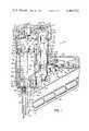
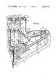
- FIG. 1is a partial, cross-sectional, side, elevational view of a fastener driving tool that is the subject of the invention, and illustrating the relative position of the principal components prior to being placed in operation;
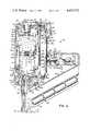
- FIG. 2is a partial, cross-sectional, side, elevational view of the fastener driver tool of FIG. 1 illustrating the position of the principal components shortly after the tool has been fired;
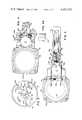
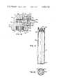
- FIG. 3is a partial, cross-sectional plan view of the fastener driver tool of FIG. 1 as viewed along line 3--3;
- FIG. 4is a partial, cross-sectional plan view of the fastener driver tool of FIG. 1 taken along line 4--4;
- FIG. 4Ais a detailed side, elevational view of the camming surface shown in FIG. 4 as viewed along line 4A--4A;
- FIG. 5is a partial, cross-sectional, plan view of the fastener driving tool of FIG. 1 taken along line 5--5;
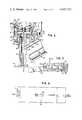
- FIG. 6is a partial, cross-sectional, side elevational view of the fastener driver tool shown in FIG. 1 illustrating the position of the major components located at the lower end of the barrel section at the end of the driving stroke;
- FIG. 7is an enlarged partial, cross-sectional, side, elevational view of the components forming the ignition mechanism
- FIG. 8is a schematic diagram illustrating the ignition circuit
- FIG. 9is a view similar to FIG. 1, but illustrating a second embodiment of a tool embodying the present invention.
- FIG. 10is a partial cross-sectional, side elevational view illustrating details of the safety trip mechanism used in the tool shown in FIG. 9;
- FIG. 11is a partial, cross-sectional, plan view of the fastener driving tool of FIG. 9 taken along line 11--11;
- FIG. 12is an enlarged cross-sectional view of the cap operation of the fuel injection mechanism of the tool illustrated in FIG. 9;
- FIG. 13is an enlarged cross-sectional view of the fuel metering valve of the present invention.
- FIG. 14is an enlarged cross-sectional view of a source of fuel used with the present invention.
- FIG. 15is a cross-sectional view taken along line 15--15 of FIG. 14.
- FIG. 1illustrates a fastener driving tool 10 the principal components of which are attached to or carried by a generally hollow housing 11.
- the housing 11 of the tool 10has three major sections: a barrel section 14; a graspable elongated handle section 15 extending horizontally outwardly from a position generally midway of the barrel section; and a base 13 extending under the barrel section and the handle section.
- a magazine assembly 16holding a row of nails disposed transversely to the path of a fastener driver 30.
- the lower end of the barrel section 14carries a guide assembly 52 which guides the fastener driver towards the workpiece.
- the magazine 16supplies fasteners serially under the fastener driver 30 into the guide assembly 52 to be driven into the workpiece.
- the base 13also supports a holder 18 containing a plurality of dry cells which form a power source or battery 20. The purpose and use of the battery will be explained at a later point in this specification.
- a fuel tank 17is mounted between the barrel section 14 and the handle section 15 of the housing 11.
- the fuel tank 17is filled with a liquified combustible gas kept under pressure, such as MAPP gas, or propane or butane, which vaporizes when it is discharged to the atmosphere.
- the fuel tank 17is supported by a pivoted lower bracket 91 and a fixed, generally U-shaped upper bracket 92.
- the lower end of the fuel tank 17defines a boss 93.
- the bossfits within a complementary opening 94 within the lower bracket 91.
- a pivot pin 95pivotally joins the lower bracket 91 with a fixed arm 96 at the lower end of the barrel section 14 of the housing 11.
- the upper end of the fuel tank 17carries a valve assembly 97 (to be hereafter described in detail) for metering fuel out of the tank.
- a flexible plastic cover 100pivotally joined to the top of the cap or cover 66 at one of its ends and to a notch 123 in the upper bracket 92 at its other end, protects the valve assembly 97.
- the cover 100is opened when the fuel tank 17 must be replaced.
- the cover 100also provides a downward force which snugly holds the lower end of the fuel tank within the lower bracket 91.
- the upper bracket 92has an inside dimension greater than the outside diameter of the fuel tank 17.
- this dimensionis selected such that if the upper end of the fuel tank is forced towards the upper end of the barrel section 14 of the housing 11, the valve assembly 97 will be actuated to dispense a metered quantity of fuel. The manner in which this is accomplished will be explained after the interior components of the tool have been described.
- an open ended cylinder 12This cylinder will hereafter be referred to as the "main cylinder.”
- the diameter of the main cylinder 12 relative to the diameter of the barrel section 14 of the housing 11is such that an open generally annular zone or region 36 is formed (See FIG. 3).
- the barrel section 14 of the housing 11is generally hollow and is provided with a number of peripheral openings or slots 120a, 120b and 120c (See FIG. 3). This allows air to pass freely around the exterior of the main cylinder 12.
- the driving piston 28is mounted within the main cylinder.
- the pistoncarries the upper end of the fastener driver 30.
- the upper end of the barrel section 15 of the housing 11carries an electrically powered fan 22 and a main valve mechanism 24 which controls the flow of air between the tool and atmosphere.
- the cylinder head 25the upper end of the barrel section of the housing which carries the electric fan 22 will be referred to as the cylinder head 25.
- the main valve mechanismincludes an upper or second cylinder 37 which together with the cylinder head 25, the main cylinder 12 and the piston 28 forms a chamber 21 which can be isolated from the atmosphere. This chamber is suitable for the combustion of a mixture of air and fuel and will be referred to hereafter as the "combustion chamber.”
- the electric fanincludes a set of blades 51 which are joined to the output shaft 49 of an electric motor 61.
- the main cylinder 12 in which the piston 28 is locatedis open at both ends.
- the support casting 26is attached to the lower end of the barrel section 14 of the housing 11 by four legs 27a, 27b, 27c and 27d (See FIG. 5).
- a hollow cavity 29is formed between the outside of the support casting 26 and the upper end of the guide assembly 52.
- a ring-shaped casting 23is used to buttress the side walls of main cylinder 12 against the interior of the barrel section 14 of the housing.
- a plurality of ports 54 piercing the side walls of the main cylinder 12are located below the ring shaped casting 23.
- An O-ring 55seals the interface between the outside wall of the main cylinder 12 and the inside wall of the support casting 26.
- a seal 56is used to plug the center of the support casting 26.
- the seal 56is preferably made of a plastic material such that it seals the inside of the main cylinder 12 from the outside of the support casting 26.
- the base or bottom of the support casting 26is provided with a plurality of axially extending ports 19. These ports interconnect the inside of the main cylinder 12 with the lower cavity 29 at the bottom of the barrel section 14.
- the piston 28is slidably mounted within the main cylinder 12 such that it is free to move reciprocatingly between the upper end (FIG. 1) and the lower end (FIG. 6) of the main cylinder.
- the downward and upward movement of the pistondefines the driving and the return strokes of the piston, respectfully.
- the piston 28carries a fastener driver 30 and a sealing means 32.
- the fastener driver 30is joined to the piston 28 by a threaded fitting 31.
- the lower end of the fastener driver 30fits within the guide assembly 52 at the lower end of the barrel section 14 of the housing 11.
- the guide assembly 52is configured to pass individual fasteners 53 discharged by the magazine 16 in such a manner that when the piston 28 is driven through its driving stroke, a fastener is driven into the workpiece W (See FIG. 2).
- the sealing means 32is formed from a plurality of O-rings disposed between the outside periphery of the piston 28 and the inside side walls of the main cylinder 12.
- the O-ringsare sized so that the frictional force between the piston 28 and the inside side walls of the main cylinder 12 is sufficiently great that, in the absence of a differential pressure across the upper face 34 and the lower face 35 of the piston, the piston will remain fixed in place relative to the interior side walls of the main cylinder.
- the cylinder 12defines an overhanging lip 12A which determines the upward movement of piston 23.
- a second cylinder 37 constituting the main valve meansis located between the upper end of the main cylinder 12 and the cylinder head 25.
- the second cylinder 37is formed from a threadably joined upper part 37a and lower part 37b.
- the second cylinder 37is slidably disposed within the upper end of the barrel section 14 of the housing 11 so that it is free to move between a raised position (See FIG. 2) and a lowered position (See FIG. 1).
- the second cylinder 37cooperates with the upper end of the main cylinder 12 to form an opening 38 (hereafter referred to as the "lower opening") between the interior of the two cylinders and the exterior of the housing 11 (See arrow 200).
- the upper end of the second cylinder 37cooperates with the cylinder head 25 to define a second opening 39 (hereafter referred to as the "upper opening").
- the openings 38, 39interconnect the combustion chamber 21 with the outside air. In the raised position both the upper opening 39 and the lower opening 38 are closed (See FIG. 2). In the lowered position (See FIG. 1) both the upper opening 39 and the lower opening 38 are exposed.
- a series of O-ringsare used to seal the interface between the second cylinder 37, the main cylinder 12 and a cylinder head 25.
- O-ring 57cooperates with the upper part 37a of the second cylinder to seal the upper opening 39
- O-ring 58carried by the outside upper edge of the main cylinder 12, cooperates with the lower end of the lower part 37b of the second cylinder to seal the lower opening 38.
- Another O-ring 59seals the joint between the upper and lower parts 37a and 37b of the second cylinder 37.
- an O-ring 60is used to seal the interface between the mounting bracket 62 holding the electric fan 22 in the cylinder head 25.
- the lower part 37b of the second cylinder 37is provided with an internal baffle or spider 67, which engages the outside of the upper end of the main cylinder 12 to limit the downward movement of cylinder 37 (See FIG. 1).
- the movement of the cylinder 37is effected by a bottom trip mechanism which functions to permit operation of the tool when it is brought into contact with the workpiece into which a fastener is to be driven.
- thisincludes a spring loaded casting that together with a set of lifting rods is used to raise and lower the second cylinder 37.
- a Y-shaped casting 40(See FIG. 5) is positioned in the cavity 29 between the guide assembly 52 at the bottom of the barrel section 14 and the lower end of the support casting 26.
- the Y-shaped casting 40features an open central hub 43 to which are attached three upwardly disposed arms 44a, 44b, and 44c.
- the lower end of the seal 56is configured to pass through an opening in the center of the hub 43 of the Y-shaped casting 40.
- the lower end of the Y-shaped casting 40defines a cylindrical mount 45 depending downwardly therefrom.
- a spring 46positioned between the lower end of the support casting 26 and the upper end of the Y-shaped casting, biases the Y-shaped casting 40 downwardly in an outward direction (See FIG. 1).
- Three lifting rods 42a, 42b, and 42cjoin the upwardly extending arms 44a, 44b, and 44c of the Y-shaped casting 40 with the lower end of the second cylinder 37 (See FIG. 5).
- a series of openings 210are provided in the ring shaped casting 23 for the lifting rods 42a, 42b, and 42c.
- a main lifting rod 48fits within the mount 45 at the lower end of the Y-shaped casting 40. The length of the main lifting rod 48 is selected such that, when the tool is in engagement with the workpiece W (See FIG. 6), the second cylinder 37 is moved from its lowered (See FIG. 1) to its raised position (See FIG. 2).
- the biasing spring 46moves the second cylinder downwardly to expose the interior of the combustion chamber 21 to the surrounding atmosphere.
- a ring-like flange 50removably joined to the lower end of the barrel section 14 of the housing 11, facilitates inspection and repair of the Y-shaped casting 40 and its associated components.
- the Y-shaped castingcauses the upward motion of the main lifting rod 48 to be transmitted to the second cylinder 37 without unduly restricting or inhibiting the flow of air and gas across the annular zone or region 36 between the outside of the main cylinder 12 and the inside of the barrel section 14 of housing 11.
- the volume or space defined by the lower face 35 of the piston 28, the inside surface of the side walls of the main cylinder 12, and inside surface of the support casting 26is sealed from the atmosphere with the exception of the ports 54 in the side walls of the main cylinder and the ports 19 at the bottom of the support casting.
- Flowis controlled through these ports by reed valves or spring loaded flapper check valves 68 and 69. As such, these check valves control the flow of air into and out of the main cylinder 12 from the surrounding atmosphere.
- the check valves 68 mounted alongside the walls of the main cylinder 12will hereafter be referred to as the "exhaust valve means,” and the check valves 69 mounted at the bottom of the support casting 26 will hereafter be referred to as the "return valve means.”
- the return valve means 69includes an O-ring 70 which cooperates with the leaf or free end of a flapper member 71 to assure that no air at the lower end of the main cylinder 12 leaks into the lower cavity 29.
- a snap ring 72holds the seal 56 and the flapper member 71 in place relative to the support casting 26.
- the cylinder head 25carries the electric fan 22, a spark plug 63 and provides an internal passageway 64 through which fuel is injected into the combustion chamber 21.
- the mounting bracket 62 for the electric fan 61is coupled to the cylinder head 25 by a resilient member 65.
- the resilient member 65absorbs the shock or force directed at electric fan 22.
- An upper cap 66holds the resilient member 65 against the cylinder head 25 and provides an anchoring point for the fuel tank cover 100.
- the handle section or handle 15 of the housing 11contains the controls used to operate the tool 10.
- the handle section 15contains: a "dead-man's" switch 75; a trigger mechanism 76; a piezo-electric firing circuit 77 which activates the spark plug 63; a portion of a fuel ejecting mechanism 78 which forces fuel into the combustion chamber 21 via the passageway 64 in the cylinder head 25; and a firing circuit interlock mechanism 80 which locks and unlocks the trigger mechanism 76.
- the dead-mans switch 75is mounted within an opening 81 at the top of the handle 15. It includes a button 82, an encapsulated electrical contact assembly 83, and an arm 84 which pivotally joins the button to the contact assembly.
- the electrical contact assembly 83is joined in series with the battery 20 formed from the dry cells mounted in the holder 18 on the base 13 of the housing 11 and the motor 61 driving the electric fan 22.
- the arm 84is biased to the "open" position (i.e., in the open position a pair of contacts within the electrical contact assembly 83 are separated so as to break the electrical circuit).
- the button 82is depressed which closes the electrical contacts within the contact assembly 83.
- the trigger mechanism 76is mounted at the lower end of the handle 15. It includes: a lever or arm 85 which is pivoted at one end by a pin 86 (FIG. 7) to the firing circuit 77 which is anchored to the inside of the handle 15; and a trigger button 87 joined to the free end of the lever by a machine screw 88 and a pin 116 (FIG. 3).
- the trigger button 87fits within an opening 79 at the lower end of the handle 15.
- the upper end of the trigger button 87is joined by a pivot pin 89 to the fuel ejecting mechanism 78.
- the trigger button 87also defines a generally U-shaped slotted opening 90 positioned between its upper and lower sections.
- the lever 85is free to move between a raised position (FIG. 2) and a lowered position (FIG. 1). The purpose of the slotted opening 90 will become apparent after the firing circuit interlock mechanism 80 is described.
- the fuel ejecting mechanism 78which acts to introduce a prescribed metered amount of fuel into the combustion chamber will now be described.
- FIG. 4a plan view of the U-shaped upper bracket 92 is presented which shows the relationship between the upper end of the fuel tank 17 and the upper end of the barrel section 14 of the housing 11.
- the valve assembly 97has an outlet nozzle 98 which is joined to the passageway 64 in the cylinder head 25.
- a spring 99biases the valve assembly 97 away from the upper end of the barrel section 14.
- the fuel ejecting mechanism 78includes: an actuating linkage 102 and a camming mechanism 103.
- the actuating linkage 102joins the upper end of the trigger button 87 with a camming mechanism 103 which is used to overcome the spring 99 and swing the upper end of fuel tank 17 inwardly in response to the movement of trigger mechanism 76.
- the lower end of the actuating linkage 102is connected to the trigger button 87 by a pivot pin 89.
- the upper end of the actuating linkage 102supports a pair of parallel transverse ears 104a and 104b. The ears in turn support two parallel wheels 108a and 108b and a shaft 106. The edges of the two wheels rest against a camming surface 110 defined at the interior of the bight portion of the upper bracket 92 (see detail, FIG. 4A).
- the shaft 106supports a roller 107 which bears against the exterior of fuel tank 17.
- the wheels 108a and 108bare driven across the camming surface 110 which moves ears 104a and 104b upwardly and inwardly towards the barrel section 14 of the housing 11.
- Thisdrives the roller 107 against the fuel tank 17 in opposition to the force of biasing spring 99.
- the upward movement of the actuating linkage 102opens the valve assembly 97 which injects a metered quantity of liquid fuel into combustion chamber 21 (See FIG. 2).
- the trigger button 87is released, the actuating linkage 102 is free to move downwardly. This resets or closes the valve assembly 97.
- the trigger mechanism 76controls the operation of the valve assembly 97 which injects fuel into the combustion chamber 21.
- FIG. 7illustrates the firing circuit 77.
- a camming mechanism 73actuated by the lever 85 and pivot pin 86, is used to force together the two crystals 77a and 77b.
- An adjustment screw 73asets the preload to the assembly.
- FIG. 8A schematic diagram of the electrical circuit between the spark plug 63 and the piezo-electric firing circuit 77 is illustrated in FIG. 8. It includes a capacitor C and a rectifier R.
- the capacitor Cstores energy until the spark discharges, and the rectifier R permits the spark to occur when the trigger is squeezed, but not when the trigger is released.
- the piezo-electric firing circuit 77is tripped when the lever 85 is raised upwardly by the trigger mechanism 76. Before the firing circuit 77 can be refired or recycled, the lever 85 must be lowered to cock the cam 73 used to force the two crystals 77a and 77b together.
- FIG. 3shows a top plan view of the major components of the firing circuit interlock mechanism 80. It includes a pair of links 112a and 112b joined together by a pair of connecting pins 114a and 114b which are connected to trigger mechanism 76 by a tension spring 115 and a pivot pin 116. The two connecting links 112a and 112b are located on either side of the fuel tank 17.
- One connecting pin 114a(hereinafter called the “lift pin”) is mounted between two lifting rods 42a and 42b which join the second cylinder 37 with the Y-shaped casting 40 (See FIG. 5).
- the other connecting pin 114b(hereinafter called the “lock pin”) fits within the slotted opening 90 in the trigger button 87.
- the pivot pin 116is carried by and links together the lever 85 operating the firing circuit 77 with the trigger button 87.
- the tension spring 115in the absence of any external force, holds the lock pin 114b within the slotted opening 90 in the trigger button 87.
- FIG. 2illustrates the arrangement of the various pins and links when the combustion chamber 21 has been isolated from the atmosphere.
- the dead-mans switch 75when the user of the tool 10 grasps the tool about its handle 15, the dead-mans switch 75 is tripped which immediately energizes the electric fan 22. This forces fresh air into the combustion chamber 21.
- the trigger mechanism 76Once the main lifting rod 48 is raised by positioning the tool 10 on the workpiece the trigger mechanism 76 is unlocked. Subsequent upward movement of the trigger button 87 activates the valve assembly 97 which injects fuel into the combustion chamber where it is thoroughly mixed with freshair by the electric fan 22. Soon thereafter the piezo-electric firing circuit 77 is tripped and a spark is produced in the combustion chamber 21 by the spark plug 63 whereupon the fuel and air mixture is ignited.
- the dead-man's switch 75is tripped which starts the electric fan 22.
- the second cylinder 37is held in its lowered position by the biasing spring 46.
- the combustion chamber 21is in communication with the surrounding atmosphere by way of the upper opening 39 and the lower opening 38 and the slots 120a, 120b, and 120c in the barrel section 14 of the housing 11. Since the electric fan 22 is running, a differential pressure is produced across the combustion chamber 21. This forces fresh air in (arrow 202) through the upper opening 39 and out (arrow 200) through the lower opening 38.
- the rotating fan blades 51produce a swirling turbulent effect within the combustion chamber 21. Any combustion gases remaining in the combustion chamber 21 due to the previous operation of the tool are thoroughly scavenged and discharged from the combustion chamber by the operation of the electric fan 22.
- the main lifting rod 48is depressed (See FIG. 2). This overcomes the force of the biasing spring 46 and forces the Y-shaped casting 40 and the associated lifting rods 42a, 42b, and 42c upwardly. This upward movement lifts the second cylinder 37 from its lowered to its raised position. Once the second cylinder 37 is in its raised position the combustion chamber 21 is isolated from the atmosphere.
- the upward movement of two of the lifting rods 42a and 42balso activates the firing circuit interlock mechanism 80.
- the upward movement of the lifting rods 42a and 42bpulls the lock pin 114b out of the slotted opening 90 in the trigger button 87. Once the lock pin 114b is free from the trigger button 87, the trigger mechanism 76 can be operated.
- the fuel ejecting mechanism 78When the user of the tool 10 forces the trigger button 87 upwardly, the fuel ejecting mechanism 78 is actuated. This forces a metered quantity of fuel into the combustion chamber 21 from the fuel tank 17.
- the upward movement of the trigger button 87operates the valve assembly 97 which forces a fixed metered quantity of fuel into the combustion chamber by way of an internal passageway 64 in the cylinder head 25. Since the blades 51 of the electric fan 22 are continuously rotating, the fuel is thoroughly mixed with the fresh air already in the combustion chamber 21. This insures rapid combustion.
- Continued upward movement of the tripper button 87eventually trips the piezo-electric firing circuit 77 which fires the spark plug 63 in the combustion chamber 21.
- the combustion gasesare free to flow out of the main cylinder 12 through the exhaust valve means 68 to the atmosphere (arrow 205).
- Studies on a prototype of the fastener driver tool 10have shown that the temperature of the gases in the combustion chamber rapidly drops from approximately 2000 degrees F. to 70 degrees F. in about 70 milliseconds due to the expansion of the gases as the piston moves downwardly and the cooling effect of the walls surrounding the expanding gases. This sudden temperature drop produces a thermal vacuum within the combustion chamber 21. Once the pressure within the combustion chamber is below atmospheric, the exhaust valve means 68 shuts off.
- the piston 28will be forced upwardly through its return stroke. Initially this upward movement is caused by the expansion of the compressed air within the compression chamber (See FIG. 6). Subsequent movement is caused by the pressure of the atmosphere since the thermal vacuum formed within the combustion chamber 21 is in the order of a few psia. Additional air is supplied to the lower face 35 of the piston 28 through the return valve means 69 which is opened by the atmospheric pressure. The piston 28 will continue upwardly until it engages cylinder lip 12A. The piston will remain suspended or at the upper end of the main cylinder 12 by virtue of the frictional engagement between the sealing means 32 and the cylinder wall plus the force of the seal 56 on the fastener driver 30 (See FIG. 1).
- the main lifting rod 48is forced outwardly by its biasing spring 46. Since the electric fan 22 is still in operation, any remaining combustion gases are forced out (arrow 200) of the lower opening 38 and fresh air is drawn in (arrow 202) through the upper opening 39. This prepares the tool 10 for firing another fastener into the workpiece.
- the trigger button 87is released the piezo-electric firing button 87 is reset or cocked for a subsequent firing.
- the lock pin 114b within the firing circuit interlock mechanism 80is forced into the slotted opening 90 in the trigger button 87. This prevents subsequent operation of the trigger mechanism 76 until the tool 10 is properly positioned on the workpiece and the combustion chamber is isolated from the atmosphere.
- FIGS. 9-12The fastener driving tool illustrated in FIGS. 9-12 is similar in many respects to that illustrated in FIGS. 1-8.
- the portions of the tool in FIG. 9 that are substantially identical with those illustrated in FIG. 1have been given the same numerals and will only be briefly referred to herein.
- the aspects of the tool in FIGS. 9-12 that differ from those illustrated in FIGS. 1-8will be dealt with in detail.
- the principal components of the second embodiment of the fastener driving tool disclosed in FIG. 9are very similar to those in FIG. 1 in that the tool in FIG. 9 contains a housing 11 including a barrel section 14, a graspable elongated handle section 15 extending outwardly from a position generally midway of the barrel section, and a base 13 extending under the barrel section and the handle section. Included in the base 13 is a magazine assembly 16 holding a row of nails diposed transversely to the path of the fastener driver 30.
- the barrel section of the toolincluding the fan, piston assembly, main valve means and a bottom trip safety mechanism are very similar to that disclosed in FIGS. 2-5 except for those differences to be discussed hereinafter.
- the mechanism for positioning the upper cylinder 37 that constitutes a main valve means to control the opening and closing of the combustion chamber 21is slightly different from that disclosed in FIG. 1.
- upward movement of the lifting rod 48 by bringing the tool into contact with the workpieceacts to move the rod support 214 upwardly against the action of the spring 46.
- the rod support 214is essentially X-shaped and includes four leg portions, 214A, 214B, 214C, and 214D. Connected to each of these leg portions are lifting rods 216A, 216B, 216C and 216D, which as shown in FIG. 10 have their upper ends disposed in the annular slot 37C of cylinder 37.
- a snap ring 238located in the top of the cylinder 12 which limits the upward movement of the piston 28, and a second snap ring 74 located within a slot in the bottom portion of the cylinder 12 which serves as a backup support for the valve 68.
- a spring 217within the cylinder mount 45, which spring is disposed between the rod support 214 and the lifting rod 48 to insure that the lifting rod will always be moved to its outward position when the tool is moved away from the workpiece, irrespective of whether or not the cylinder 37 has been moved to its downward position by the action of the spring 46.
- FIG. 9Another difference between the two embodiments is the bottom safety mechanism disclosed in FIG. 9, which prevents movement of the trigger to bring about firing of the tool until the tool engages a workpiece.
- the tool of FIG. 9employs a safety latch mechanism 226, which when the tool is out of engagement with the workpiece is positioned so that the latch arm 228 thereof prevents trigger actuating movement of the trigger 218 by virtue of engagement between the latch arm 228 and the flange 224 that extends outwardly from the trigger leg 222 of the trigger 218.
- the trigger latch 226is maintained in the position shown by the action of a torsion spring 232 which is located about the pin 231 whereby the safety latch is connected to the tool housing 11.
- the latch 226is moved out of engagement with the trigger 218 by the upward movement of the lifting rod 48.
- the lifting rod 48connected to the ring 234 through the cylindrical mount 45.
- the ring 234has an arm 236 that is normally in engagement with the latch arm 230.
- the ring arm 236pivots the safety latch 226 in a clockwise direction to move the latch arm 228 out of engagement with flange 224.
- the trigger 218is now free to move and its upward movement moves the lever 220, which actuates the piezo-electric circuit to send a charge to spark plug 63 and ignite the fuel and air mixture contained in the combustion chamber.
- the upward movement of the cylinder 37results in introducing a metered amount of fuel into the combustion chamber through passageway 64. This occurs as a result of the cylinder 37 engaging the depending arm 210 of the cap 206, which acts to swing the cap 206 upwardly and move the tank 17 in a counterclockwise direction to actuate the fuel valve assembly 97 inwardly to dispense a metered amount of fuel into the chamber 21.
- the upward movement of the lifting rodmoves the safety latch 226 in a clockwise direction to disengage the latch from the trigger mechanism to permit the trigger 218 to move upwardly. Upward movement of the trigger 218 results in actuating the piezo-electric firing circuit which fires the spark plug 63 in the combustion chamber 21.
- the pistonis then driven to drive a nail into a workpiece.
- the return action of the piston and the scavenging of the combustion chamberis identical to that which occurs in the tool of FIG. 1, and further repetition of that opertion is not believed necessary.
- Valve 300includes a valve body 301 having a fuel inlet stem 202, and a fuel outlet stem 303 having passages 304 and 305, respectively.
- Valve body 301includes a bushing 306 seated within a generally cylindrical cavity 307, and bushing 306 is provided with a cylindrical cavity 308 which defines a metering chamber.
- a coil spring 310is mounted in a cylindrical cavity 311 in valve body 301 and bears against a spring seat 312 carried at the reduced diameter end 313 of stem 303.
- An O-ring 314is disposed around stem portion 313, and is loosely received between a flange 315 on bushing 306 and a gasket 317.
- a plug 318is threadably received within valve body 301 and bears against a flexible gasket 319. Plug 318 supports stem 303 for axial movement with respect thereto.
- Radially extending outlet openings 320are provided in stem 303 for discharging liquid fuel in atomized form into the passage 64 leading to the combustion chamber.
- the metered charge of liquid fuel within metering chamber 308is placed in fluid communication with passage 305 when stem 303 is moved inwardly, since openings 320 are disposed to the left of gasket 319, and the liquified gaseous fuel expands into the combustion chamber through passages 305 and 64.
- the stem 303is shifted to the right, as viewed in FIG. 13, under the influence of spring 310, the inclined portion of stem 303 moves away from O-ring 314 and a fresh charge of liquid fuel passes into chamber 308 between stem portion 313 and O-ring 314.
- Metering valve body 301is associated with liquified gas container 330 by the insertion of inlet stem 302 within an outlet passage 331 at the upper end of container 330.
- the outlet passage 331is associated with a conventional valve 332, forming no part of the present invention.
- the container 330is preferably formed of metal to provide appropriate bursting strength, and supported within container 330 is a bag 333 of generally cruciform shape which has a threaded upper end 334 threadably associated with valve 332. Bag 333 is collapsible, and contains therewithin a given volume of liquified gas.
- a suitable propellant 335such as propane, is provided between the bag 333 and the inner wall of container 330 for applying pressure to bag 333 for expelling liquid fuel outwardly of valve 332, and into the metering valve through inlet passage 304.
- a suitable lubricating mediumis associated with, and dispersed within the liquid fuel in bag 333.
- the lubricating mediummay take the form of a lubricating oil, which is mixed as a minor percent with the liquid gas in bag 333. It has been found that such a lubricating medium not only does not significantly detract from ignition of the liquid fuel in the combustion chamber or from flame propagation therewithin, but also reduces wear on the moving parts thus prolonging the useful life of the metering valve and other moving parts of the tool.
Landscapes
- Engineering & Computer Science (AREA)
- Mechanical Engineering (AREA)
- Chemical & Material Sciences (AREA)
- Combustion & Propulsion (AREA)
- General Engineering & Computer Science (AREA)
- Portable Nailing Machines And Staplers (AREA)
- Perforating, Stamping-Out Or Severing By Means Other Than Cutting (AREA)
- Wire Bonding (AREA)
- Details Of Spanners, Wrenches, And Screw Drivers And Accessories (AREA)
- Road Paving Machines (AREA)
- Yarns And Mechanical Finishing Of Yarns Or Ropes (AREA)
- Gas Separation By Absorption (AREA)
- Silver Salt Photography Or Processing Solution Therefor (AREA)
- Dental Preparations (AREA)
- Treatments For Attaching Organic Compounds To Fibrous Goods (AREA)
- Curing Cements, Concrete, And Artificial Stone (AREA)
- Processing Of Solid Wastes (AREA)
Abstract
Description
Claims (29)
Priority Applications (26)
| Application Number | Priority Date | Filing Date | Title |
|---|---|---|---|
| US06/227,194US4403722A (en) | 1981-01-22 | 1981-01-22 | Combustion gas powered fastener driving tool |
| IL64694AIL64694A (en) | 1981-01-22 | 1982-01-01 | Self-starting portable tool and method of using same for driving a fastener |
| IN14/DEL/82AIN157476B (en) | 1981-01-22 | 1982-01-06 | |
| NZ199536ANZ199536A (en) | 1981-01-22 | 1982-01-20 | Combustion gas powered fastener driving tool |
| PH26761APH20783A (en) | 1981-01-22 | 1982-01-20 | Portable gaspowered tool with linear motor |
| AR288489DAR228635A1 (en) | 1981-01-22 | 1982-01-20 | LINEAR MOTOR DRIVEN PORTABLE TOOL |
| EP82100443AEP0056990B1 (en) | 1981-01-22 | 1982-01-21 | Combustion gas powered fastener driving tool |
| KR8200251AKR890000720B1 (en) | 1981-01-22 | 1982-01-21 | Tableting machine using combustion gas as power |
| NO820183ANO156520C (en) | 1981-01-22 | 1982-01-21 | SUSTAINABLE TOOL FOR RECOVERY OF MOUNTING ELEMENTS. |
| DE8282100443TDE3277616D1 (en) | 1981-01-22 | 1982-01-21 | Combustion gas powered fastener driving tool |
| JP57008244AJPS57178676A (en) | 1981-01-22 | 1982-01-21 | Portable fastener driving tool and its driving method |
| PT74323APT74323B (en) | 1981-01-22 | 1982-01-21 | Process for driving portable tools with a combustion gases powered linear motor and portable tools using such a process |
| CA000394615ACA1170801A (en) | 1981-01-22 | 1982-01-21 | Combustion gas powered fastener driving tool |
| DK026382ADK168882B1 (en) | 1981-01-22 | 1982-01-21 | Portable combustion gas powered tool and method for recovering fasteners. |
| IE122/82AIE57459B1 (en) | 1981-01-22 | 1982-01-21 | Portable gas-powered tool with linear motor |
| SU823388088ASU1768024A3 (en) | 1981-01-22 | 1982-01-21 | Portable drive tool for fastening |
| FI820190AFI76950C (en) | 1981-01-22 | 1982-01-21 | Exhaust-driven wrapping tool for fasteners. |
| AT82100443TATE30692T1 (en) | 1981-01-22 | 1982-01-21 | COMBUSTION GAS ACTUATED ATTACHMENT TOOL. |
| ES508986AES508986A0 (en) | 1981-01-22 | 1982-01-22 | IMPROVEMENTS IN A PORTABLE DRIVING TOOL FOR FASTENING ELEMENTS SUCH AS NAIL STAPLES OR SIMILAR. |
| ZA82449AZA82449B (en) | 1981-01-22 | 1982-01-22 | Combustion gas powered fastener driving tool |
| AU79747/82AAU548857B2 (en) | 1981-01-22 | 1982-01-22 | Combustion gas powered fastener driving tool |
| MX191107AMX155598A (en) | 1981-01-22 | 1982-01-22 | IMPROVEMENTS TO INTERNAL COMBUSTION PORTABLE TOOL, FOR NAILING STAPLES AND NAILS |
| BR8200347ABR8200347A (en) | 1981-01-22 | 1982-01-22 | PORTABLE FIXER APPLICATION TOOL AND FIXER APPLICATION PROCESS |
| US06/490,409US4483474A (en) | 1981-01-22 | 1983-05-02 | Combustion gas-powered fastener driving tool |
| SU4202980/06ARU2039644C1 (en) | 1981-01-22 | 1987-07-28 | Self-controlled portable tool |
| JP63297145AJPH01188284A (en) | 1981-01-22 | 1988-11-24 | Fastener driving method |
Applications Claiming Priority (1)
| Application Number | Priority Date | Filing Date | Title |
|---|---|---|---|
| US06/227,194US4403722A (en) | 1981-01-22 | 1981-01-22 | Combustion gas powered fastener driving tool |
Related Child Applications (1)
| Application Number | Title | Priority Date | Filing Date |
|---|---|---|---|
| US06/490,409Continuation-In-PartUS4483474A (en) | 1981-01-22 | 1983-05-02 | Combustion gas-powered fastener driving tool |
Publications (1)
| Publication Number | Publication Date |
|---|---|
| US4403722Atrue US4403722A (en) | 1983-09-13 |
Family
ID=22852146
Family Applications (1)
| Application Number | Title | Priority Date | Filing Date |
|---|---|---|---|
| US06/227,194Expired - LifetimeUS4403722A (en) | 1981-01-22 | 1981-01-22 | Combustion gas powered fastener driving tool |
Country Status (17)
| Country | Link |
|---|---|
| US (1) | US4403722A (en) |
| EP (1) | EP0056990B1 (en) |
| JP (2) | JPS57178676A (en) |
| KR (1) | KR890000720B1 (en) |
| AT (1) | ATE30692T1 (en) |
| AU (1) | AU548857B2 (en) |
| BR (1) | BR8200347A (en) |
| CA (1) | CA1170801A (en) |
| DE (1) | DE3277616D1 (en) |
| DK (1) | DK168882B1 (en) |
| ES (1) | ES508986A0 (en) |
| FI (1) | FI76950C (en) |
| IN (1) | IN157476B (en) |
| MX (1) | MX155598A (en) |
| NO (1) | NO156520C (en) |
| NZ (1) | NZ199536A (en) |
| ZA (1) | ZA82449B (en) |
Cited By (212)
| Publication number | Priority date | Publication date | Assignee | Title |
|---|---|---|---|---|
| US4534500A (en)* | 1981-12-28 | 1985-08-13 | Hilti Aktiengesellschaft | Setting device with a driving piston propelled by high pressure gases |
| USRE32452E (en)* | 1981-01-22 | 1987-07-07 | Signode Corporation | Portable gas-powered tool with linear motor |
| US4717060A (en)* | 1986-07-02 | 1988-01-05 | Senco Products, Inc. | Self-contained internal combustion fastener driving tool |
| EP0251684A1 (en)* | 1986-07-02 | 1988-01-07 | Senco Products, Inc | Cam-controlled self-contained internal combustion fastener driving tool |
| EP0252653A1 (en)* | 1986-07-02 | 1988-01-13 | Senco Products, Inc | Simplified self-contained internal combustion fastener driving tool |
| US4773581A (en)* | 1986-06-13 | 1988-09-27 | Hitachi Koki Company, Ltd. | Combustion gas powered tool |
| US4821683A (en)* | 1983-04-18 | 1989-04-18 | Veldman Alphonsus G | Portable power tool with improved combustion chamber charging means |
| US4913331A (en)* | 1988-10-21 | 1990-04-03 | Hitachi Koki Company, Ltd. | Internal-combustion piston driving apparatus having a decompression channel |
| US5090606A (en)* | 1989-10-27 | 1992-02-25 | Hitachi Koki Company, Limited | Combustion gas powered fastener driving tool |
| EP0519239A2 (en) | 1991-06-17 | 1992-12-23 | Illinois Tool Works Inc. | Photoelectric switch sealed against infiltration of contaminants |
| US5191861A (en)* | 1991-07-12 | 1993-03-09 | Stanley-Bostitch, Inc. | Internal combustion actuated portable tool |
| US5197646A (en)* | 1992-03-09 | 1993-03-30 | Illinois Tool Works Inc. | Combustion-powered tool assembly |
| EP0642892A1 (en)* | 1993-08-30 | 1995-03-15 | Illinois Tool Works Inc. | Combined ignition and fuel system for combustion-powered tool |
| US5443345A (en)* | 1994-06-20 | 1995-08-22 | Illinois Tool Works Inc. | Fastener-sleeve assembly and strip of collated fasteners |
| US5489484A (en)* | 1993-04-05 | 1996-02-06 | Black & Decker Inc. | Battery pack for cordless device |
| EP0695605A2 (en) | 1994-08-01 | 1996-02-07 | Illinois Tool Works Inc. | Fastener-driving tool and positioning mechanism for it |
| EP0711634A2 (en) | 1994-11-10 | 1996-05-15 | Illinois Tool Works Inc. | System for controlling energy output of combustion-powered, fastener-driving tool |
| EP0726122A1 (en) | 1995-02-13 | 1996-08-14 | Illinois Tool Works Inc. | Combustion-powered, fastener-driving tool with gas-actuated, fastener-feeding mechanism |
| EP0775553A1 (en) | 1995-11-27 | 1997-05-28 | Illinois Tool Works Inc. | Combustion-powered fastener driving tool |
| US5636427A (en)* | 1995-10-06 | 1997-06-10 | Scovill Fasteners Inc. | Hand-held snap fastener closer |
| US5687898A (en)* | 1995-02-15 | 1997-11-18 | Societe De Prospection Et D'inventions Techniques (Spit) | Fixing apparatus with a compressed gas-powered piston |
| US5687899A (en)* | 1995-04-19 | 1997-11-18 | Illinois Tool Works Inc. | Portable fastener driver using inflammable gas |
| US5713313A (en)* | 1997-02-07 | 1998-02-03 | Illinois Tool Works Inc. | Combustion powered tool with dual fans |
| US5752643A (en)* | 1995-05-23 | 1998-05-19 | Applied Tool Development Corporation | Internal combustion powered tool |
| US5794831A (en)* | 1996-07-12 | 1998-08-18 | Illinois Tool Works Inc. | Fastener detection and firing control system for powered fastener driving tools |
| US5799855A (en)* | 1996-02-09 | 1998-09-01 | Illinois Tool Works Inc. | Velocity control and nosepiece stabilizer system for combustion powered tools |
| US5909836A (en)* | 1997-10-31 | 1999-06-08 | Illinois Tool Works Inc. | Combustion powered tool with combustion chamber lockout |
| US5988477A (en)* | 1998-06-03 | 1999-11-23 | Illinois Tools Works, Inc. | Nosepiece shield for combustion powered tool |
| US6123241A (en)* | 1995-05-23 | 2000-09-26 | Applied Tool Development Corporation | Internal combustion powered tool |
| US6164510A (en)* | 1998-06-03 | 2000-12-26 | Illinois Tool Works Inc. | Nosepiece shield for combustion powered tool |
| US6176412B1 (en) | 1998-04-20 | 2001-01-23 | Illinois Tool Works Inc. | Fastener driving tool for trim applications |
| USRE37092E1 (en) | 1993-01-13 | 2001-03-13 | Streamlight, Inc. | Flashlight and recharging system therefor |
| US6302297B1 (en) | 2000-09-06 | 2001-10-16 | Illinois Tool Works Inc. | External metering valve for a fuel cell |
| USD457811S1 (en) | 2000-09-06 | 2002-05-28 | Illinois Tool Works Inc. | Fuel canister dispensing valve |
| EP0765715B1 (en)* | 1995-09-29 | 2002-06-12 | Illinois Tool Works Inc. | Combustion-powered, fastener-driving tool |
| US6474953B2 (en)* | 2000-02-22 | 2002-11-05 | Atlas Copco Airpower, Naamloze Vennootschap | Compressor control system and method for controlling the same |
| EP1260321A2 (en) | 2001-04-30 | 2002-11-27 | Illinois Tool Works Inc. | Trim-type fastener driving tool |
| US6520397B1 (en) | 1997-12-22 | 2003-02-18 | Illinois Tool Works Inc. | Combustion powered tool with improved combustion chamber fan motor suspension |
| FR2833199A1 (en)* | 2001-12-10 | 2003-06-13 | Hilti Ag | Fuel tank for combustion powered nail driver tool has tank shaped to fit around part of driver housing |
| US6619527B1 (en) | 2000-10-10 | 2003-09-16 | Illinois Tool Works Inc. | Combustion powered tool suspension for iron core fan motor |
| EP1388394A1 (en)* | 2002-08-09 | 2004-02-11 | Hitachi Koki Co., Ltd. | Combustion-powered nail gun |
| US20040026476A1 (en)* | 2002-08-09 | 2004-02-12 | Hitachi Koki Co., Ltd. | Combustion-powered nail gun |
| US6695195B2 (en) | 2002-06-03 | 2004-02-24 | Hitachi Koki Co., Ltd. | Combustion-powered nail gun |
| US20040050901A1 (en)* | 2002-09-12 | 2004-03-18 | Turk Robert L. | Fan motor suspension mount for a combustion-powered tool |
| US20040056063A1 (en)* | 2002-09-25 | 2004-03-25 | Ulrich Rosenbaum | Hand-guided working tool, in particular a fuel-driven setting tool |
| US6722550B1 (en) | 2003-05-09 | 2004-04-20 | Illinois Tool Works Inc. | Fuel level indicator for combustion tools |
| DE10218194B4 (en)* | 2002-04-24 | 2004-05-13 | Hilti Ag | Setting tool that can be driven by expanding gases |
| FR2847501A1 (en)* | 2002-11-26 | 2004-05-28 | Hilti Ag | Fixing components e.g. nail, drive tool, has current source with generator to convert energy resulting from combustion of driving medium to electrical energy, where generator has coils arranged on magazine cooperating with piston |
| US6779493B2 (en) | 2002-06-13 | 2004-08-24 | Illinois Tool Works Inc. | Combustion mechanism for generating a flame jet |
| US6786378B2 (en) | 2002-01-09 | 2004-09-07 | Illinois Tool Works Inc. | Fastener tool having auxiliary fuel cell metering valve stem seal adaptor |
| EP1459850A1 (en)* | 2003-03-19 | 2004-09-22 | Hitachi Koki Co., Ltd. | Combustion type power tool having avoiding unit for avoiding overheating to mechanical components in the tool |
| US20040238588A1 (en)* | 2003-06-02 | 2004-12-02 | Makita Corporation | Combustion power tool |
| EP1488891A2 (en) | 2003-06-20 | 2004-12-22 | Hitachi Koki Co., Ltd. | Combustion-powered driving tool |
| US20050001003A1 (en)* | 2003-06-02 | 2005-01-06 | Frederic Nayrac | Gas-operated apparatus with combustion chamber |
| US20050029323A1 (en)* | 2002-08-09 | 2005-02-10 | Hitachi Koki Co., Ltd. | Combustion-powered nail gun |
| WO2005011924A1 (en) | 2003-07-31 | 2005-02-10 | Max Co., Ltd. | Gas combusion-type impact device |
| US20050035171A1 (en)* | 2003-08-11 | 2005-02-17 | Shinki Ohtsu | Combustion type power tool facilitating cleaning to internal cleaning target |
| US20050056072A1 (en)* | 2003-09-16 | 2005-03-17 | Schmidt Christopher J. | Power crimping tool |
| US20050098123A1 (en)* | 2003-11-07 | 2005-05-12 | Makita Corporation | Combustion power tool |
| US20050116006A1 (en)* | 2003-11-27 | 2005-06-02 | Tomomasa Nishikawa | Combustion chamber arrangement in combustion type power tool |
| US20050156007A1 (en)* | 2004-01-16 | 2005-07-21 | Tomomasa Nishikawa | Combustion type power tool having fan |
| EP1559514A1 (en)* | 2004-01-30 | 2005-08-03 | Hitachi Koki Co., Ltd. | Combustion type power tool having segmental connection unit |
| US20050173484A1 (en)* | 2004-02-09 | 2005-08-11 | Moeller Larry M. | Combustion chamber control for combustion-powered fastener-driving tool |
| WO2005077607A1 (en) | 2004-02-09 | 2005-08-25 | Illinois Tool Works, Inc. | Exhaust system for combustion-powered fastener-driving tool |
| WO2005077605A1 (en) | 2004-02-09 | 2005-08-25 | Illinois Tool Works Inc. | Combustion chamber control for combustion-powered fastener-driving tool |
| US20050218186A1 (en)* | 2004-04-02 | 2005-10-06 | Michael Forster | Method for sizing a motor for a power tool |
| US20050218174A1 (en)* | 2004-04-02 | 2005-10-06 | Kenney James J | Activation arm configuration for a power tool |
| US20050217876A1 (en)* | 2004-04-02 | 2005-10-06 | Kenney James J | Activation arm assembly method |
| US20050218185A1 (en)* | 2004-04-02 | 2005-10-06 | Kenney James J | Cam and clutch configuration for a power tool |
| US20050224552A1 (en)* | 2004-04-02 | 2005-10-13 | Alan Berry | Flywheel configuration for a power tool |
| US20050242154A1 (en)* | 2004-04-30 | 2005-11-03 | Leimbach Richard L | Cordless fastener driving tool |
| US20050247276A1 (en)* | 2004-05-10 | 2005-11-10 | Shoichi Hirai | Combustion type power tool having fin for effectively cooling cylinder |
| US20050263113A1 (en)* | 2004-05-10 | 2005-12-01 | Hitachi Koki Co., Ltd. | Combustion type nailing machine |
| EP1479483A3 (en)* | 2003-05-23 | 2006-01-04 | Illinois Tool Works Inc. | Combustion apparatus having improved airflow |
| US20060006207A1 (en)* | 2004-07-09 | 2006-01-12 | Yoshitaka Akiba | Combustion type power tool having buffer piece |
| US20060022013A1 (en)* | 2004-07-20 | 2006-02-02 | Paul Gaudron | Gas charge setting tool |
| US20060042566A1 (en)* | 2004-08-31 | 2006-03-02 | Aichi Machine Industry Co., Ltd | Internal combustion engine |
| US20060042571A1 (en)* | 2004-09-01 | 2006-03-02 | Panasik Cheryl L | Fuel cell compartment for combustion-powered tool |
| US20060060628A1 (en)* | 2004-08-30 | 2006-03-23 | Larkin John F | Combustion fastener |
| US20060102108A1 (en)* | 2004-11-18 | 2006-05-18 | Panasik Cheryl L | Combustion-powered tool fuel heating system |
| US20060102111A1 (en)* | 2004-11-16 | 2006-05-18 | Yasuki Ohmori | Combustion-type power tool |
| US20060129009A1 (en)* | 2004-11-25 | 2006-06-15 | Tomomasa Nishikawa | Fuel, gas, combustion type power tool driven by the fuel gas, and compressed gas container for the combustion type power tool |
| US20060144889A1 (en)* | 2004-12-20 | 2006-07-06 | Tomomasa Nishikawa | Combustion-type power tool with exhaust gas flow regulating rib |
| EP1693156A2 (en) | 2005-02-18 | 2006-08-23 | Hitachi Koki Co., Ltd. | Combustion-type power tool having switch protection arrangement |
| US20060186166A1 (en)* | 2005-02-18 | 2006-08-24 | Yoshitaka Akiba | Combustion-type power tool |
| US7138595B2 (en) | 2004-04-02 | 2006-11-21 | Black & Decker Inc. | Trigger configuration for a power tool |
| US20070045377A1 (en)* | 2005-08-25 | 2007-03-01 | Hilti Aktiengensellschaft | Pneumatically driven setting tool |
| US20070074706A1 (en)* | 2005-10-03 | 2007-04-05 | Wagdy Mohamed K | Actuation structure for internal fuel cell metering valve and associated combustion tool |
| US20070074684A1 (en)* | 2005-10-05 | 2007-04-05 | Hilti Aktiengesellschaft | Combustion-engined setting tool |
| US20070131731A1 (en)* | 2004-02-09 | 2007-06-14 | Moeller Larry M | Combustion chamber distance control for combustion-powered fastener-driving tool |
| US20070181596A1 (en)* | 2006-01-27 | 2007-08-09 | Max Co., Ltd. | Gas cartridge |
| US20070187426A1 (en)* | 2006-01-27 | 2007-08-16 | Max Co, Ltd. | Gas cartridge |
| US20070210132A1 (en)* | 2006-03-08 | 2007-09-13 | Yoshitaka Akiba | Combustion Type Power Tool Having Sealing Arrangement |
| EP1332836A3 (en)* | 2002-02-04 | 2007-09-19 | Illinois Tool Works Inc. | Integrated spark and switch unit for combustion fastener driving tool and said fastener driving tool |
| US20070222198A1 (en)* | 2006-03-23 | 2007-09-27 | Green David J | Multi-firing combustion actuated device and related methods for firing re-deployable automotive safety devices |
| US20070221697A1 (en)* | 2006-03-22 | 2007-09-27 | Hilti Aktiengesellschaft | Combustion-engine setting tool |
| US20070237591A1 (en)* | 2006-04-06 | 2007-10-11 | Oliver Ohlendorf | Electrical hand-held tool with a cooling fan |
| US20070251967A1 (en)* | 2006-04-26 | 2007-11-01 | Taylor Walter J | Fuel cell actuator and associated combustion tool |
| US20070295727A1 (en)* | 2006-01-27 | 2007-12-27 | Keijiro Murayama | Gas cartridge |
| US20080008929A1 (en)* | 1993-04-05 | 2008-01-10 | Wheeler Dale K | Tool system having rechargeable battery pack |
| CN100364722C (en)* | 2002-12-19 | 2008-01-30 | 希尔蒂股份公司 | Combustion - powered working tool, in particular a setting tool for fastening elements |
| US7325710B1 (en)* | 2006-10-24 | 2008-02-05 | De Poan Pneumatic Corp. | Pneumatic nail gun |
| US7331403B2 (en) | 2004-04-02 | 2008-02-19 | Black & Decker Inc. | Lock-out for activation arm mechanism in a power tool |
| EP1894679A2 (en) | 1998-04-20 | 2008-03-05 | Illinois Tool Works Inc. | Fastener driving tool for trim applications |
| US20080110953A1 (en)* | 2004-04-19 | 2008-05-15 | Gibson Eric S | Interchangeable adapter for in-can and on-can fuel cells |
| WO2008085465A2 (en) | 2006-12-29 | 2008-07-17 | Illinois Tool Works Inc. | Cordless fastener tool with fastener driving and rotating functions |
| US20080203133A1 (en)* | 2005-06-29 | 2008-08-28 | Max Co Ltd | Hand-Held Power Tool |
| US20080223895A1 (en)* | 2007-03-15 | 2008-09-18 | Hitachi Koki Co., Ltd. | Combustion-powered tool with improved ignition starting feature |
| US20080308593A1 (en)* | 2007-03-15 | 2008-12-18 | Yoshitaka Akiba | Combustion type power tool |
| US20080314952A1 (en)* | 2006-02-23 | 2008-12-25 | Junichi Tamura | Driving Piston Maintaining Structure in Gas Nailer |
| US20080314953A1 (en)* | 2007-06-21 | 2008-12-25 | Illinois Tool Works Inc. | Feeder mechanism retention device for fastener driving tool |
| US20090001120A1 (en)* | 2006-06-30 | 2009-01-01 | Shea Maureen L | Enhanced fuel passageway and adapter for combustion tool fuel cell |
| US20090008423A1 (en)* | 2007-01-19 | 2009-01-08 | Yasuo Sasaki | Combustion type driving tool |
| US20090020583A1 (en)* | 2007-07-17 | 2009-01-22 | Kyle Kestner | Actuator pin guide for a fastener driving tool |
| US7503401B2 (en) | 2004-04-02 | 2009-03-17 | Black & Decker Inc. | Solenoid positioning methodology |
| US20090095249A1 (en)* | 2007-10-16 | 2009-04-16 | Panasik Cheryl L | Air filter assembly for combustion tool |
| US20090145945A1 (en)* | 2007-12-10 | 2009-06-11 | Heinzen William J | Power tool having a mating battery |
| US20090159635A1 (en)* | 2007-12-21 | 2009-06-25 | Thomas Sperrfechter | Combustion-operated setting tool |
| US7556184B2 (en) | 2007-06-11 | 2009-07-07 | Black & Decker Inc. | Profile lifter for a nailer |
| CN100571994C (en)* | 2004-09-01 | 2009-12-23 | 伊利诺斯器械工程公司 | Fuel tank compartment for combustion power tools |
| US20090314817A1 (en)* | 2005-11-17 | 2009-12-24 | Larry Moeller | Variable Ignition Delay for Combustion Nailer |
| US20090321493A1 (en)* | 2005-11-15 | 2009-12-31 | Larry Moeller | One way valve for combustion tool fan motor |
| US20100003107A1 (en)* | 2008-07-03 | 2010-01-07 | Hilti Aktiengesellschaft | Auxiliary constructional component |
| US20100012699A1 (en)* | 2008-07-15 | 2010-01-21 | Chia-Sheng Liang | Control mechanism for Pneumatic Nail Guns |
| US20100032467A1 (en)* | 2006-12-05 | 2010-02-11 | Max Co., Ltd. | Gas combustion type driving tool |
| WO2010030453A1 (en) | 2008-09-12 | 2010-03-18 | Illinois Tool Works Inc. | Combustion power source with back pressure release for combustion powered fastener-driving tool |
| CN101678540A (en)* | 2007-06-29 | 2010-03-24 | 美克司株式会社 | Gas combustion type driving tool |
| US7686199B2 (en) | 2004-04-02 | 2010-03-30 | Black & Decker Inc. | Lower bumper configuration for a power tool |
| US20100096429A1 (en)* | 2008-10-22 | 2010-04-22 | Superior Power Tool Co., Ltd. | Gas can mounting structure for gas nail gun |
| US20100108735A1 (en)* | 2007-04-02 | 2010-05-06 | Max Co., Ltd. | Gas internal combustion type nailing machine |
| CN101142060B (en)* | 2005-03-15 | 2010-05-19 | 伊利诺斯器械工程公司 | Exhaust check valve for combustion nailer |
| US20100127038A1 (en)* | 2008-11-26 | 2010-05-27 | Superior Power Tool Co., Ltd | Gas can mounting structure for gas-operated nail gun |
| US7726536B2 (en) | 2004-04-02 | 2010-06-01 | Black & Decker Inc. | Upper bumper configuration for a power tool |
| US20100176180A1 (en)* | 2009-01-12 | 2010-07-15 | Superior Power Tool Co., Ltd. | Gas nail gun |
| US7789169B2 (en) | 2004-04-02 | 2010-09-07 | Black & Decker Inc. | Driver configuration for a power tool |
| US20100237125A1 (en)* | 2009-03-18 | 2010-09-23 | Basso Industry Corp. | Nail Gun and Safety Device of the Same |
| US20100243702A1 (en)* | 2009-03-27 | 2010-09-30 | Hon Kan Cheung | Apparatus for shooting a nail |
| WO2010114657A1 (en) | 2009-03-31 | 2010-10-07 | Illinois Tool Works Inc. | Single switched dual firing condition combustion nailer |
| US20100258607A1 (en)* | 2009-04-13 | 2010-10-14 | Stanley Fastening Systems, L.P. | Fastener driving device with contact trip having an electrical actuator |
| US20100258608A1 (en)* | 2007-06-21 | 2010-10-14 | Porth Chris H | Fastener feeder delay for fastener driving tool |
| US20110049212A1 (en)* | 2009-09-03 | 2011-03-03 | Taylor Walter J | Fuel cell actuation mechanism for combustion-powered tool |
| US20110073630A1 (en)* | 2009-09-25 | 2011-03-31 | Makita Corporation | Driving tool |
| US20110084109A1 (en)* | 2009-10-09 | 2011-04-14 | Illinois Tool Works Inc. | Automatic low power consumption mode for combustion tools |
| WO2011049821A1 (en) | 2009-10-22 | 2011-04-28 | Illinois Tool Works Inc. | Fuel level monitoring system for combustion-powered tools |
| US7975893B2 (en) | 2004-04-02 | 2011-07-12 | Black & Decker Inc. | Return cord assembly for a power tool |
| US20110180582A1 (en)* | 2010-01-26 | 2011-07-28 | Societe De Prospection Et D'inventions Techniques Spit | Pressure-temperature abacus and a fuel cartridge, a device for transferring fuel and a hand fastening tool with a pressure sensor |
| US20110204118A1 (en)* | 2006-10-16 | 2011-08-25 | Illinois Tool Works Inc. | Recharge cycle function for combustion nailer |
| US20110239398A1 (en)* | 2010-04-05 | 2011-10-06 | Makita Corporation | Dust collecting devices |
| US20120097727A1 (en)* | 2009-06-25 | 2012-04-26 | Societe De Prospection Et D'inventions Techniques Spit | Fastening tool for fastening members with a fuel injector |
| WO2012068007A1 (en) | 2010-11-15 | 2012-05-24 | Illinois Tool Works Inc. | Fastener driving tool |
| US20120132690A1 (en)* | 2010-11-25 | 2012-05-31 | Hilti Aktiengesellschaft | Fastener driving tool |
| US8231039B2 (en) | 2004-04-02 | 2012-07-31 | Black & Decker Inc. | Structural backbone/motor mount for a power tool |
| CN102672676A (en)* | 2011-02-22 | 2012-09-19 | 美克司株式会社 | Gas combustion type driving tool |
| DE112011100056T5 (en) | 2010-04-13 | 2012-10-04 | Illionois Tool Works Inc. | Fuel cell with flange and positioning structure for combustion-powered tool |
| US8302833B2 (en) | 2004-04-02 | 2012-11-06 | Black & Decker Inc. | Power take off for cordless nailer |
| WO2012162297A1 (en) | 2011-05-23 | 2012-11-29 | Illinois Tool Works Inc. | Stud miss indicator for fastening driving tool |
| WO2013003502A1 (en) | 2011-06-30 | 2013-01-03 | Illinois Tool Works Inc. | Fuel cell adapter |
| WO2013013155A1 (en) | 2011-07-21 | 2013-01-24 | Illinois Tool Works Inc. | Portable combustion gas-powered tools with combustion chamber lockout system |
| WO2013033054A1 (en) | 2011-08-31 | 2013-03-07 | Illinois Tool Works Inc. | High efficiency engine for combustion nailer |
| WO2013055979A1 (en) | 2011-10-12 | 2013-04-18 | Illinois Tool Works Inc. | Interface for fuel delivery system for combustion nailer |
| US8485410B1 (en) | 2008-09-02 | 2013-07-16 | High Wind Products, Inc. | Nail gun magazine for stacked fasteners |
| DE202013007908U1 (en) | 2013-09-09 | 2013-10-18 | Olaf Kersten | Propellant gas for combustion-powered setting devices |
| US8579175B2 (en)* | 2011-03-01 | 2013-11-12 | Illinois Tool Works Inc. | Valve cap for pneumatic nailer |
| WO2013169696A2 (en) | 2012-05-11 | 2013-11-14 | Illinois Tool Works Inc. | Lockout for fastener-driving tool |
| US8591242B2 (en) | 2010-04-08 | 2013-11-26 | Illinois Tool Works Inc. | Floating battery contact module for a power tool |
| WO2014011508A1 (en) | 2012-07-10 | 2014-01-16 | Illinois Tool Works Inc. | Fastener driving tool with fastener driving and rotating mechanism |
| CN103639988A (en)* | 2013-12-03 | 2014-03-19 | 台州市大江实业有限公司 | Gas staple gun with interior convenient to clean |
| US8679665B2 (en) | 2007-12-10 | 2014-03-25 | Illinois Tool Works Inc. | Battery for a power tool |
| DE102005000200B4 (en)* | 2005-12-21 | 2014-07-03 | Hilti Aktiengesellschaft | Internal combustion setting device |
| WO2014113199A1 (en) | 2013-01-15 | 2014-07-24 | Illinois Tool Works Inc. | Reversion trigger for combustion-powered fastener-driving tool |
| US20140299646A1 (en)* | 2011-10-13 | 2014-10-09 | Poly Systems Pty Ltd | Hand held power tool for driving fasteners |
| US20140367441A1 (en)* | 2013-06-18 | 2014-12-18 | Basso Industry Corporation | Combustion-type power tool |
| US20150047608A1 (en)* | 2012-04-03 | 2015-02-19 | Illinois Tool Works Inc. | Removable adapter for air and fuel intake and mixing in a combustion tool |
| WO2015069363A1 (en) | 2013-11-06 | 2015-05-14 | Illinois Tool Works Inc. | Fastener driving tool with an automatic nose chamber guide member |
| WO2015073688A1 (en) | 2013-11-18 | 2015-05-21 | Illinois Tool Works Inc. | Faceted fastener driver bumper with cooling slots |
| DE202015003264U1 (en) | 2015-05-06 | 2015-06-01 | Olaf Kersten | Gas operated setting tool |
| DE202015003261U1 (en) | 2015-05-06 | 2015-06-01 | Olaf Kersten | Gas operated setting tool |
| DE202015003265U1 (en) | 2015-05-06 | 2015-06-03 | Olaf Kersten | Gas operated setting tool |
| DE202015003262U1 (en) | 2015-05-06 | 2015-06-03 | Olaf Kersten | Gas operated setting tool |
| DE202015003581U1 (en) | 2015-05-20 | 2015-07-06 | Olaf Kersten | Gas operated setting tool |
| DE202015003579U1 (en) | 2015-05-19 | 2015-07-06 | Olaf Kersten | Gas operated setting tool |
| WO2015134076A1 (en) | 2014-03-03 | 2015-09-11 | Illinois Tool Works Inc. | Interface for fuel delivery system for combustion fastener driver |
| US20150343625A1 (en)* | 2013-01-18 | 2015-12-03 | Illinois Tool Works Inc. | Electropneumatic gas fastening device |
| WO2016018197A1 (en)* | 2014-07-28 | 2016-02-04 | Ashmann Marshall | Multi-cycle stratified internal combustion system |
| WO2016137571A1 (en) | 2015-02-25 | 2016-09-01 | Illinois Tool Works Inc. | Fuel and propellant composition for combustion tools |
| US20160303725A1 (en)* | 2013-11-26 | 2016-10-20 | Hilti Aktiengesellschaft | Pyrotechnic driving device |
| US20170106516A1 (en)* | 2015-10-14 | 2017-04-20 | Basso Industry Corp. | Fuel transmitting device |
| US9662777B2 (en) | 2013-08-22 | 2017-05-30 | Techtronic Power Tools Technology Limited | Pneumatic fastener driver |
| WO2017091442A1 (en) | 2015-11-25 | 2017-06-01 | Illinois Tool Works Inc. | Adapter for combustion tool fuel cells |
| US20170259417A1 (en)* | 2016-03-11 | 2017-09-14 | Max Co., Ltd. | Driving tool |
| US9802303B2 (en) | 2010-04-13 | 2017-10-31 | Illinois Tool Works Inc. | Interface for fuel delivery system for combustion fastener driver |
| USD812101S1 (en) | 2016-05-27 | 2018-03-06 | Illinois Tool Works Inc. | Combination fuel cell adapter and cap |
| WO2018128818A1 (en)* | 2017-01-06 | 2018-07-12 | Illinois Tool Works Inc. | Powered fastener-driving tool including an engaging element to frictionally engage a piston upon returning to a pre-firing position |
| US10040183B2 (en) | 2013-10-11 | 2018-08-07 | Illinois Tool Works Inc. | Powered nailer with positive piston return |
| USD828398S1 (en) | 2016-12-08 | 2018-09-11 | Illinois Tool Works Inc. | Fuel cell metering valve |
| US10335937B2 (en) | 2012-06-05 | 2019-07-02 | Illinois Tool Works Inc. | Fastener-driving tool including a fastening result detector |
| WO2019112870A3 (en)* | 2017-12-05 | 2019-08-22 | Illinois Tool Works Inc. | Powered fastener driving tools and clean lubricants therefor |
| US10518396B2 (en)* | 2014-12-23 | 2019-12-31 | Tti (Macao Commercial Offshore) Limited | Drive blade lubrication assembly and powered fastener driver containing the same |
| US10598377B2 (en) | 2016-05-27 | 2020-03-24 | Illinois Tool Works Inc. | Combustion-powered fastener driving tool fuel cell assembly |
| US10875165B2 (en) | 2017-08-02 | 2020-12-29 | Illinois Tool Works Inc. | Fastener-driving tool with one or more combustion chambers and an exhaust gas recirculation system |
| US10882172B2 (en) | 2004-04-02 | 2021-01-05 | Black & Decker, Inc. | Powered hand-held fastening tool |
| US20210213595A1 (en)* | 2016-07-29 | 2021-07-15 | Koki Holdings Co., Ltd. | Driver |
| US11426851B2 (en) | 2019-08-21 | 2022-08-30 | Illinois Tool Works Inc. | Fastener driving tool |
| US11466815B2 (en) | 2017-10-06 | 2022-10-11 | Black & Decker Inc. | Hydrogen fuel canister |
| USD1001736S1 (en) | 2020-09-01 | 2023-10-17 | Illinois Tool Works Inc. | Fuel cell adapter for tool |
| US11978915B2 (en) | 2020-09-01 | 2024-05-07 | Illinois Tool Works Inc. | Combustion-powered fastener driving tool fuel cell adapter |
| US11992925B2 (en) | 2021-11-23 | 2024-05-28 | Illinois Tool Works Inc. | Fuel cell adapter for fastener driving tool |
| US12070843B2 (en) | 2021-11-23 | 2024-08-27 | Illinois Tool Works Inc. | Combustion chamber ring for fastener driving tool |
| US12179327B2 (en) | 2020-12-16 | 2024-12-31 | Illinois Tool Works Inc. | Fastener driving device |
| US12251809B2 (en) | 2021-11-23 | 2025-03-18 | Illinois Tool Works Inc. | Dosing lever for fastener driving tool |
| US12343009B2 (en) | 2021-06-07 | 2025-07-01 | Lexington Medical, Inc. | Motorized surgical handle assembly |
| US12414766B2 (en) | 2017-04-07 | 2025-09-16 | Lexington Medical, Inc. | Surgical handle assembly |
Families Citing this family (23)
| Publication number | Priority date | Publication date | Assignee | Title |
|---|---|---|---|---|
| AU572133B2 (en)* | 1983-04-18 | 1988-05-05 | Veldman, A.G.G. | Percussive tool with improved combustion chamber |
| US4483473A (en)* | 1983-05-02 | 1984-11-20 | Signode Corporation | Portable gas-powered fastener driving tool |
| JPS62297076A (en)* | 1986-06-13 | 1987-12-24 | 日立工機株式会社 | Gas-fired piston drive device |
| US4712379A (en)* | 1987-01-08 | 1987-12-15 | Pow-R Tools Corporation | Manual recycler for detonating impact tool |
| AU629232B2 (en)* | 1988-08-12 | 1992-10-01 | Veldman, Alphonsus G.G. | Power tool drive system |
| US5263439A (en)* | 1992-11-13 | 1993-11-23 | Illinois Tool Works Inc. | Fuel system for combustion-powered, fastener-driving tool |
| DE10034016C1 (en)* | 2000-07-13 | 2002-01-03 | Hilti Ag | Fuel gas for fuel-driven tool, especially tool for fixing nails or bolts, based on combustible gas, contains fragrance (mixture), e.g. eugenol, isoeugenol and clove oil in mixture of dimethyl ether, propylene and isobutane |
| DE10048311B4 (en)* | 2000-09-29 | 2012-03-01 | Hilti Aktiengesellschaft | setting tool |
| DE10318555B3 (en)* | 2003-04-24 | 2004-11-25 | Hilti Ag | Blowing agent container for setting tools and combustion-powered setting tool |
| JP2005144608A (en)* | 2003-11-17 | 2005-06-09 | Makita Corp | Combustion type working tool |
| FR2870770B1 (en)* | 2004-05-27 | 2006-08-11 | Prospection Et D Inv S Techniq | GAS FIXING APPARATUS WITH FRONT FLOATING HEATER MOUNTED HEAT ENGINE |
| JP4534667B2 (en)* | 2004-08-24 | 2010-09-01 | 日立工機株式会社 | Combustion power tool |
| US7097083B2 (en)* | 2004-09-01 | 2006-08-29 | Illinois Tool Works Inc. | Cage and offset upper probe assembly for fastener-driving tool |
| FR2884894B1 (en)* | 2005-04-22 | 2007-06-29 | Prospection Et D Inv S Techniq | COMBUSTION GAS CARTRIDGE FOR GAS FIXING APPARATUS |
| JP4935978B2 (en) | 2006-08-09 | 2012-05-23 | マックス株式会社 | Valve device for combustion chamber in gas-fired driving tool |
| JP5011888B2 (en) | 2006-08-22 | 2012-08-29 | マックス株式会社 | Gas fired driving tool |
| JP2008255813A (en) | 2007-04-02 | 2008-10-23 | Max Co Ltd | Gas internal combustion type nail driver |
| AU2008201129B2 (en)* | 2007-04-04 | 2011-01-27 | Hilti Ag | Combustion-operated setting tool |
| JP5070957B2 (en) | 2007-06-29 | 2012-11-14 | マックス株式会社 | Gas fired driving tool |
| JP5286945B2 (en)* | 2008-05-30 | 2013-09-11 | 日立工機株式会社 | Combustion nailer |
| KR200476698Y1 (en)* | 2013-11-18 | 2015-03-23 | 제일타카 주식회사 | Shooting apparatus for insulation fastener |
| TWI532571B (en)* | 2015-10-12 | 2016-05-11 | Electric nail gun drive device | |
| CN111347375B (en)* | 2020-02-17 | 2022-11-01 | 天津大学 | A liquid nitrogen nail gun device |
Citations (10)
| Publication number | Priority date | Publication date | Assignee | Title |
|---|---|---|---|---|
| US3042008A (en)* | 1958-10-18 | 1962-07-03 | Liesse Maurice | Striking machine, chiefly nailing, clamping and the like percussion machines |
| US3858781A (en)* | 1973-05-14 | 1975-01-07 | Fastener Corp | Safety mechanism for fastener driving tool |
| DE2552106A1 (en)* | 1974-11-20 | 1976-05-26 | Max Co Ltd | Internal combustion driven impact tool - has driving piston cylinder connected by valve to combustion chamber round outside |
| US3967771A (en)* | 1974-12-16 | 1976-07-06 | Smith James E | Self-contained impact tool |
| JPS523772A (en)* | 1975-06-28 | 1977-01-12 | Max Co Ltd | Impact tool with internal combustion chamber |
| JPS5334179A (en)* | 1976-09-13 | 1978-03-30 | Max Co Ltd | Automatic return device for piston of internal combustion tool |
| JPS53115980A (en)* | 1977-03-19 | 1978-10-09 | Max Co Ltd | Valve arrangement for use in internal combustion type percussive tool |
| JPS53115981A (en)* | 1977-03-19 | 1978-10-09 | Max Co Ltd | Internal combustion type tool |
| US4260092A (en)* | 1979-07-02 | 1981-04-07 | Duo-Fast Corporation | Safety assembly for a tool for driving fasteners |
| US4331277A (en)* | 1980-05-23 | 1982-05-25 | United States Surgical Corporation | Self-contained gas powered surgical stapler |
Family Cites Families (4)
| Publication number | Priority date | Publication date | Assignee | Title |
|---|---|---|---|---|
| DE703206C (en)* | 1935-07-16 | 1941-03-04 | Meco Brennkraft Maschinen G M | Inlet organ for internal combustion shaker and vibration devices |
| US3850359A (en)* | 1973-05-11 | 1974-11-26 | Fastener Corp | Fastener driving tool |
| CA1080401A (en)* | 1976-08-12 | 1980-07-01 | Maurice Liesse | Explosion impact device and accessories for vailing, fastening, etc. |
| US4200213A (en)* | 1977-08-10 | 1980-04-29 | Agence Nationale De Valorisation De La Recherche (Anvar) | Percussion apparatus |
- 1981
- 1981-01-22USUS06/227,194patent/US4403722A/ennot_activeExpired - Lifetime
- 1982
- 1982-01-06ININ14/DEL/82Apatent/IN157476B/enunknown
- 1982-01-20NZNZ199536Apatent/NZ199536A/enunknown
- 1982-01-21DEDE8282100443Tpatent/DE3277616D1/ennot_activeExpired
- 1982-01-21KRKR8200251Apatent/KR890000720B1/ennot_activeExpired
- 1982-01-21ATAT82100443Tpatent/ATE30692T1/enactive
- 1982-01-21DKDK026382Apatent/DK168882B1/enactive
- 1982-01-21NONO820183Apatent/NO156520C/ennot_activeIP Right Cessation
- 1982-01-21JPJP57008244Apatent/JPS57178676A/enactiveGranted
- 1982-01-21CACA000394615Apatent/CA1170801A/ennot_activeExpired
- 1982-01-21EPEP82100443Apatent/EP0056990B1/ennot_activeExpired
- 1982-01-21FIFI820190Apatent/FI76950C/ennot_activeIP Right Cessation
- 1982-01-22ESES508986Apatent/ES508986A0/enactiveGranted
- 1982-01-22ZAZA82449Apatent/ZA82449B/enunknown
- 1982-01-22AUAU79747/82Apatent/AU548857B2/ennot_activeExpired
- 1982-01-22BRBR8200347Apatent/BR8200347A/ennot_activeIP Right Cessation
- 1982-01-22MXMX191107Apatent/MX155598A/enunknown
- 1988
- 1988-11-24JPJP63297145Apatent/JPH01188284A/enactiveGranted
Patent Citations (10)
| Publication number | Priority date | Publication date | Assignee | Title |
|---|---|---|---|---|
| US3042008A (en)* | 1958-10-18 | 1962-07-03 | Liesse Maurice | Striking machine, chiefly nailing, clamping and the like percussion machines |
| US3858781A (en)* | 1973-05-14 | 1975-01-07 | Fastener Corp | Safety mechanism for fastener driving tool |
| DE2552106A1 (en)* | 1974-11-20 | 1976-05-26 | Max Co Ltd | Internal combustion driven impact tool - has driving piston cylinder connected by valve to combustion chamber round outside |
| US3967771A (en)* | 1974-12-16 | 1976-07-06 | Smith James E | Self-contained impact tool |
| JPS523772A (en)* | 1975-06-28 | 1977-01-12 | Max Co Ltd | Impact tool with internal combustion chamber |
| JPS5334179A (en)* | 1976-09-13 | 1978-03-30 | Max Co Ltd | Automatic return device for piston of internal combustion tool |
| JPS53115980A (en)* | 1977-03-19 | 1978-10-09 | Max Co Ltd | Valve arrangement for use in internal combustion type percussive tool |
| JPS53115981A (en)* | 1977-03-19 | 1978-10-09 | Max Co Ltd | Internal combustion type tool |
| US4260092A (en)* | 1979-07-02 | 1981-04-07 | Duo-Fast Corporation | Safety assembly for a tool for driving fasteners |
| US4331277A (en)* | 1980-05-23 | 1982-05-25 | United States Surgical Corporation | Self-contained gas powered surgical stapler |
Cited By (398)
| Publication number | Priority date | Publication date | Assignee | Title |
|---|---|---|---|---|
| USRE32452E (en)* | 1981-01-22 | 1987-07-07 | Signode Corporation | Portable gas-powered tool with linear motor |
| US4534500A (en)* | 1981-12-28 | 1985-08-13 | Hilti Aktiengesellschaft | Setting device with a driving piston propelled by high pressure gases |
| US4821683A (en)* | 1983-04-18 | 1989-04-18 | Veldman Alphonsus G | Portable power tool with improved combustion chamber charging means |
| US4773581A (en)* | 1986-06-13 | 1988-09-27 | Hitachi Koki Company, Ltd. | Combustion gas powered tool |
| US4721240A (en)* | 1986-07-02 | 1988-01-26 | Senco Products, Inc. | Cam-controlled self-contained internal combustion fastener driving tool |
| EP0252653A1 (en)* | 1986-07-02 | 1988-01-13 | Senco Products, Inc | Simplified self-contained internal combustion fastener driving tool |
| EP0251684A1 (en)* | 1986-07-02 | 1988-01-07 | Senco Products, Inc | Cam-controlled self-contained internal combustion fastener driving tool |
| EP0251685A1 (en)* | 1986-07-02 | 1988-01-07 | Senco Products, Inc | Self-contained internal combustion fastener driving tool |
| US4717060A (en)* | 1986-07-02 | 1988-01-05 | Senco Products, Inc. | Self-contained internal combustion fastener driving tool |
| US4913331A (en)* | 1988-10-21 | 1990-04-03 | Hitachi Koki Company, Ltd. | Internal-combustion piston driving apparatus having a decompression channel |
| US5090606A (en)* | 1989-10-27 | 1992-02-25 | Hitachi Koki Company, Limited | Combustion gas powered fastener driving tool |
| AU645906B2 (en)* | 1991-06-17 | 1994-01-27 | Illinois Tool Works Inc. | Photoelectric switch sealed against infiltration of contaminants |
| EP0519239A2 (en) | 1991-06-17 | 1992-12-23 | Illinois Tool Works Inc. | Photoelectric switch sealed against infiltration of contaminants |
| US5191861A (en)* | 1991-07-12 | 1993-03-09 | Stanley-Bostitch, Inc. | Internal combustion actuated portable tool |
| US5197646A (en)* | 1992-03-09 | 1993-03-30 | Illinois Tool Works Inc. | Combustion-powered tool assembly |
| USRE37092E1 (en) | 1993-01-13 | 2001-03-13 | Streamlight, Inc. | Flashlight and recharging system therefor |
| US5489484A (en)* | 1993-04-05 | 1996-02-06 | Black & Decker Inc. | Battery pack for cordless device |
| US20080008929A1 (en)* | 1993-04-05 | 2008-01-10 | Wheeler Dale K | Tool system having rechargeable battery pack |
| US7550213B2 (en) | 1993-04-05 | 2009-06-23 | Black & Decker Inc. | Tool system having rechargeable battery pack |
| EP0642892A1 (en)* | 1993-08-30 | 1995-03-15 | Illinois Tool Works Inc. | Combined ignition and fuel system for combustion-powered tool |
| US5443345A (en)* | 1994-06-20 | 1995-08-22 | Illinois Tool Works Inc. | Fastener-sleeve assembly and strip of collated fasteners |
| EP0688964A1 (en) | 1994-06-20 | 1995-12-27 | Illinois Tool Works Inc. | Fastener-sleeve assembly and strip of collated fasteners |
| EP0695605A2 (en) | 1994-08-01 | 1996-02-07 | Illinois Tool Works Inc. | Fastener-driving tool and positioning mechanism for it |
| EP0711634A2 (en) | 1994-11-10 | 1996-05-15 | Illinois Tool Works Inc. | System for controlling energy output of combustion-powered, fastener-driving tool |
| EP0726122A1 (en) | 1995-02-13 | 1996-08-14 | Illinois Tool Works Inc. | Combustion-powered, fastener-driving tool with gas-actuated, fastener-feeding mechanism |
| US5687898A (en)* | 1995-02-15 | 1997-11-18 | Societe De Prospection Et D'inventions Techniques (Spit) | Fixing apparatus with a compressed gas-powered piston |
| EP0738565B1 (en)* | 1995-04-19 | 2000-06-28 | Illinois Tool Works Inc. | Portable fastener driver using inflammable gas |
| US5687899A (en)* | 1995-04-19 | 1997-11-18 | Illinois Tool Works Inc. | Portable fastener driver using inflammable gas |
| US6213370B1 (en) | 1995-05-23 | 2001-04-10 | Applied Tool Development Corporation | Internal combustion powered tool |
| US6247626B1 (en) | 1995-05-23 | 2001-06-19 | Applied Tool Development Corporation | Internal combustion powered tool |
| US5873508A (en)* | 1995-05-23 | 1999-02-23 | Applied Tool Development Corporation | Internal combustion powered tool |
| US6311887B1 (en) | 1995-05-23 | 2001-11-06 | Applied Tool Development Corporation | Internal combustion powered tool |
| US6318615B1 (en) | 1995-05-23 | 2001-11-20 | Applied Tool Development Corporation | Internal combustion powered tool |
| US6223963B1 (en) | 1995-05-23 | 2001-05-01 | J. Oscar Aparacio, Jr. | Internal combustion powered tool |
| US5752643A (en)* | 1995-05-23 | 1998-05-19 | Applied Tool Development Corporation | Internal combustion powered tool |
| US6123241A (en)* | 1995-05-23 | 2000-09-26 | Applied Tool Development Corporation | Internal combustion powered tool |
| EP0765715B1 (en)* | 1995-09-29 | 2002-06-12 | Illinois Tool Works Inc. | Combustion-powered, fastener-driving tool |
| US5636427A (en)* | 1995-10-06 | 1997-06-10 | Scovill Fasteners Inc. | Hand-held snap fastener closer |
| US5971245A (en)* | 1995-11-27 | 1999-10-26 | Illinois Tool Works Inc. | Fuel injection system for combustion-powered tool |
| US5680980A (en)* | 1995-11-27 | 1997-10-28 | Illinois Tool Works Inc. | Fuel injection system for combustion-powered tool |
| EP0775553A1 (en) | 1995-11-27 | 1997-05-28 | Illinois Tool Works Inc. | Combustion-powered fastener driving tool |
| US5897043A (en)* | 1996-02-09 | 1999-04-27 | Illinois Tool Works Inc. | Velocity control and nosepiece stabilizer system for combustion powered tools |
| US5799855A (en)* | 1996-02-09 | 1998-09-01 | Illinois Tool Works Inc. | Velocity control and nosepiece stabilizer system for combustion powered tools |
| US5794831A (en)* | 1996-07-12 | 1998-08-18 | Illinois Tool Works Inc. | Fastener detection and firing control system for powered fastener driving tools |
| US5713313A (en)* | 1997-02-07 | 1998-02-03 | Illinois Tool Works Inc. | Combustion powered tool with dual fans |
| US5909836A (en)* | 1997-10-31 | 1999-06-08 | Illinois Tool Works Inc. | Combustion powered tool with combustion chamber lockout |
| US6520397B1 (en) | 1997-12-22 | 2003-02-18 | Illinois Tool Works Inc. | Combustion powered tool with improved combustion chamber fan motor suspension |
| EP0925880A3 (en)* | 1997-12-22 | 2004-05-06 | Illinois Tool Works Inc. | Suspension mechanism for a combustion chamber fan motor of a combustion powered tool |
| US6176412B1 (en) | 1998-04-20 | 2001-01-23 | Illinois Tool Works Inc. | Fastener driving tool for trim applications |
| EP1894679A2 (en) | 1998-04-20 | 2008-03-05 | Illinois Tool Works Inc. | Fastener driving tool for trim applications |
| US6179192B1 (en) | 1998-04-20 | 2001-01-30 | Illinois Tool Works Inc. | Fastener driving tool for trim applications |
| US5988477A (en)* | 1998-06-03 | 1999-11-23 | Illinois Tools Works, Inc. | Nosepiece shield for combustion powered tool |
| US6164510A (en)* | 1998-06-03 | 2000-12-26 | Illinois Tool Works Inc. | Nosepiece shield for combustion powered tool |
| US6474953B2 (en)* | 2000-02-22 | 2002-11-05 | Atlas Copco Airpower, Naamloze Vennootschap | Compressor control system and method for controlling the same |
| EP1186553A2 (en) | 2000-09-06 | 2002-03-13 | Illinois Tool Works Inc. | External metering valve for a fuel cell |
| USD457811S1 (en) | 2000-09-06 | 2002-05-28 | Illinois Tool Works Inc. | Fuel canister dispensing valve |
| US6302297B1 (en) | 2000-09-06 | 2001-10-16 | Illinois Tool Works Inc. | External metering valve for a fuel cell |
| AU2004203202B2 (en)* | 2000-10-10 | 2007-08-09 | Illinois Tool Works Inc. | Combustion powered tool |
| EP1798000A1 (en)* | 2000-10-10 | 2007-06-20 | Illinois Tool Works Inc. | Combustion powered tool suspension for iron core fan motor |
| US6619527B1 (en) | 2000-10-10 | 2003-09-16 | Illinois Tool Works Inc. | Combustion powered tool suspension for iron core fan motor |
| EP1260321A2 (en) | 2001-04-30 | 2002-11-27 | Illinois Tool Works Inc. | Trim-type fastener driving tool |
| DE10160575C1 (en)* | 2001-12-10 | 2003-06-18 | Hilti Ag | setting tool |
| FR2833199A1 (en)* | 2001-12-10 | 2003-06-13 | Hilti Ag | Fuel tank for combustion powered nail driver tool has tank shaped to fit around part of driver housing |
| US6786378B2 (en) | 2002-01-09 | 2004-09-07 | Illinois Tool Works Inc. | Fastener tool having auxiliary fuel cell metering valve stem seal adaptor |
| EP1327501A3 (en)* | 2002-01-09 | 2004-10-06 | Illinois Tool Works Inc. | Fastener tool having auxiliary fuel cell metering valve stem seal adaptor |
| KR100939072B1 (en)* | 2002-01-09 | 2010-01-28 | 일리노이즈 툴 워크스 인코포레이티드 | Metering Valve Assemblies, Metering Valve-Tool Stem Assemblies and Combustion Powered Fasteners |
| EP1332836A3 (en)* | 2002-02-04 | 2007-09-19 | Illinois Tool Works Inc. | Integrated spark and switch unit for combustion fastener driving tool and said fastener driving tool |
| DE10218194B4 (en)* | 2002-04-24 | 2004-05-13 | Hilti Ag | Setting tool that can be driven by expanding gases |
| US6695195B2 (en) | 2002-06-03 | 2004-02-24 | Hitachi Koki Co., Ltd. | Combustion-powered nail gun |
| US6779493B2 (en) | 2002-06-13 | 2004-08-24 | Illinois Tool Works Inc. | Combustion mechanism for generating a flame jet |
| US6889885B2 (en) | 2002-08-09 | 2005-05-10 | Hitachi Koki Co., Ltd. | Combustion-powered nail gun |
| US6783045B2 (en) | 2002-08-09 | 2004-08-31 | Hitachi Koki Co., Ltd. | Combustion-powered nail gun |
| US20040026476A1 (en)* | 2002-08-09 | 2004-02-12 | Hitachi Koki Co., Ltd. | Combustion-powered nail gun |
| EP1388394A1 (en)* | 2002-08-09 | 2004-02-11 | Hitachi Koki Co., Ltd. | Combustion-powered nail gun |
| AU2003231693B2 (en)* | 2002-08-09 | 2008-06-05 | Hitachi Koki Co., Ltd. | Combustion-powered Nail Gun |
| US20040026475A1 (en)* | 2002-08-09 | 2004-02-12 | Hitachi Koki Co., Ltd. | Combustion-powered nail gun |
| US7427007B2 (en) | 2002-08-09 | 2008-09-23 | Hitachi Koki Co., Ltd. | Combustion-powered nail gun |
| US20060283909A1 (en)* | 2002-08-09 | 2006-12-21 | Hitachi Koki Co.,Ltd. | Combustion-powered nail gun |
| US20050029323A1 (en)* | 2002-08-09 | 2005-02-10 | Hitachi Koki Co., Ltd. | Combustion-powered nail gun |
| US7108164B2 (en) | 2002-08-09 | 2006-09-19 | Hitachi Koki Co., Ltd. | Combustion-powered nail gun |
| US20060065691A1 (en)* | 2002-08-09 | 2006-03-30 | Hitachi Koki Co., Ltd. | Combustion-powered nail gun |
| US6983871B2 (en) | 2002-08-09 | 2006-01-10 | Hitachi Koki Co., Ltd. | Combustion-powered nail gun |
| US20060289596A1 (en)* | 2002-09-12 | 2006-12-28 | Turk Robert L | Fan motor suspension mount for a combustion-powered tool |
| US7568602B2 (en)* | 2002-09-12 | 2009-08-04 | Illinois Tool Works Inc. | Fan motor suspension mount for a combustion-powered tool |
| US7118018B2 (en)* | 2002-09-12 | 2006-10-10 | Illinois Tool Works Inc. | Fan motor suspension mount for a combustion-powered tool |
| US20040050901A1 (en)* | 2002-09-12 | 2004-03-18 | Turk Robert L. | Fan motor suspension mount for a combustion-powered tool |
| US7040520B2 (en)* | 2002-09-12 | 2006-05-09 | Illinois Tool Works Inc. | Fan motor suspension mount for a combustion-powered tool |
| US20040173657A1 (en)* | 2002-09-12 | 2004-09-09 | Turk Robert L. | Fan motor suspension mount for a combustion-powered tool |
| US20040056063A1 (en)* | 2002-09-25 | 2004-03-25 | Ulrich Rosenbaum | Hand-guided working tool, in particular a fuel-driven setting tool |
| FR2844736A1 (en)* | 2002-09-25 | 2004-03-26 | Hilti Ag | Hand-guided working tool for driving fastening unit e.g., nail, has voltage source formed by capacitor, which are arranged in setting tool and are connected to discharge side of electrical circuit comprising electrical consumers |
| DE10254965B4 (en)* | 2002-11-26 | 2021-05-06 | Hilti Aktiengesellschaft | Internal combustion-powered setting tool |
| FR2847501A1 (en)* | 2002-11-26 | 2004-05-28 | Hilti Ag | Fixing components e.g. nail, drive tool, has current source with generator to convert energy resulting from combustion of driving medium to electrical energy, where generator has coils arranged on magazine cooperating with piston |
| CN100364722C (en)* | 2002-12-19 | 2008-01-30 | 希尔蒂股份公司 | Combustion - powered working tool, in particular a setting tool for fastening elements |
| EP1459850A1 (en)* | 2003-03-19 | 2004-09-22 | Hitachi Koki Co., Ltd. | Combustion type power tool having avoiding unit for avoiding overheating to mechanical components in the tool |
| US20040182336A1 (en)* | 2003-03-19 | 2004-09-23 | Yasuki Ohmori | Combustion type power tool having avoiding unit for avoiding overheating to mechanical components in the tool |
| US7021251B2 (en) | 2003-03-19 | 2006-04-04 | Hitachi Koki Co., Ltd. | Combustion type power tool having avoiding unit for avoiding overheating to mechanical components in the tool |
| CN100411824C (en)* | 2003-03-19 | 2008-08-20 | 日立工机株式会社 | Combustion-type power tools with preventive devices to avoid overheating of mechanical parts in the tool |
| US6722550B1 (en) | 2003-05-09 | 2004-04-20 | Illinois Tool Works Inc. | Fuel level indicator for combustion tools |
| CN100390384C (en)* | 2003-05-23 | 2008-05-28 | 伊利诺斯器械工程公司 | Combustion apparatus having improved airflow |
| EP1479483A3 (en)* | 2003-05-23 | 2006-01-04 | Illinois Tool Works Inc. | Combustion apparatus having improved airflow |
| EP1484138A3 (en)* | 2003-06-02 | 2006-10-25 | Makita Corporation | Combustion power tool |
| US20050001003A1 (en)* | 2003-06-02 | 2005-01-06 | Frederic Nayrac | Gas-operated apparatus with combustion chamber |
| US20040238588A1 (en)* | 2003-06-02 | 2004-12-02 | Makita Corporation | Combustion power tool |
| US7243829B2 (en) | 2003-06-02 | 2007-07-17 | Makita Corporation | Combustion power tool |
| US7036704B2 (en)* | 2003-06-02 | 2006-05-02 | Societe Prospection Et D'inventions Techniques Spit | Gas-operated apparatus with combustion chamber |
| EP1488891A2 (en) | 2003-06-20 | 2004-12-22 | Hitachi Koki Co., Ltd. | Combustion-powered driving tool |
| AU2004202711B2 (en)* | 2003-06-20 | 2006-04-27 | Hitachi Koki Co., Ltd. | Combustion-powered Driving Tool |
| US20060237513A1 (en)* | 2003-07-31 | 2006-10-26 | Hiroshi Tanaka | Gas combusion-type impact device |
| EP1649982A4 (en)* | 2003-07-31 | 2007-05-23 | Max Co Ltd | Gas combusion-type impact device |
| WO2005011924A1 (en) | 2003-07-31 | 2005-02-10 | Max Co., Ltd. | Gas combusion-type impact device |
| US7308996B2 (en) | 2003-07-31 | 2007-12-18 | Max Co., Ltd. | Gas combustion-type impact device |
| US7261071B2 (en) | 2003-08-11 | 2007-08-28 | Hitachi Koki Co., Ltd. | Combustion type power tool facilitating cleaning to internal cleaning target |
| US20050035171A1 (en)* | 2003-08-11 | 2005-02-17 | Shinki Ohtsu | Combustion type power tool facilitating cleaning to internal cleaning target |
| US7044090B2 (en) | 2003-08-11 | 2006-05-16 | Hitachi Koki Co., Ltd. | Combustion type power tool facilitating cleaning to internal cleaning target |
| CN100345663C (en)* | 2003-08-11 | 2007-10-31 | 日立工机株式会社 | Combustion type power tool convenient for cleaning its internal object to be cleaned |
| US20050056072A1 (en)* | 2003-09-16 | 2005-03-17 | Schmidt Christopher J. | Power crimping tool |
| US7146837B2 (en) | 2003-09-16 | 2006-12-12 | Schmidt Christopher J | Power crimping tool |
| US7461766B2 (en) | 2003-11-07 | 2008-12-09 | Makita Corporation | Combustion power tool |
| US20050098123A1 (en)* | 2003-11-07 | 2005-05-12 | Makita Corporation | Combustion power tool |
| US20060151565A1 (en)* | 2003-11-27 | 2006-07-13 | Tomomasa Nishikawa | Combustion chamber arrangement in combustion type power tool |
| US7458493B2 (en) | 2003-11-27 | 2008-12-02 | Hitachi Koki Co., Ltd. | Combustion chamber arrangement in combustion type power tool |
| US20050116006A1 (en)* | 2003-11-27 | 2005-06-02 | Tomomasa Nishikawa | Combustion chamber arrangement in combustion type power tool |
| US7066117B2 (en) | 2003-11-27 | 2006-06-27 | Hitachi Koki Co., Ltd. | Combustion chamber arrangement in combustion type power tool |
| US20050156007A1 (en)* | 2004-01-16 | 2005-07-21 | Tomomasa Nishikawa | Combustion type power tool having fan |
| US7743955B2 (en) | 2004-01-16 | 2010-06-29 | Hitachi Koki Co., Ltd. | Combustion type power tool having fan |
| US20070138231A1 (en)* | 2004-01-30 | 2007-06-21 | Yoshitaka Akiba | Combustion type power tool having segmental connection unit |
| EP1559514A1 (en)* | 2004-01-30 | 2005-08-03 | Hitachi Koki Co., Ltd. | Combustion type power tool having segmental connection unit |
| US20050167464A1 (en)* | 2004-01-30 | 2005-08-04 | Yoshitaka Akiba | Combustion type power tool having segmental connection unit |
| US7182237B2 (en) | 2004-01-30 | 2007-02-27 | Hitachi Koki Co., Ltd. | Combustion type power tool having segmental connection unit |
| WO2005077605A1 (en) | 2004-02-09 | 2005-08-25 | Illinois Tool Works Inc. | Combustion chamber control for combustion-powered fastener-driving tool |
| US20100163594A1 (en)* | 2004-02-09 | 2010-07-01 | Moeller Larry M | Combustion chamber distance control for combustion-powered fastener-driving tool |
| WO2005077607A1 (en) | 2004-02-09 | 2005-08-25 | Illinois Tool Works, Inc. | Exhaust system for combustion-powered fastener-driving tool |
| US20050173484A1 (en)* | 2004-02-09 | 2005-08-11 | Moeller Larry M. | Combustion chamber control for combustion-powered fastener-driving tool |
| US7673779B2 (en) | 2004-02-09 | 2010-03-09 | Illinois Tool Works Inc. | Combustion chamber distance control combustion-powered fastener-driving tool |
| US20070131731A1 (en)* | 2004-02-09 | 2007-06-14 | Moeller Larry M | Combustion chamber distance control for combustion-powered fastener-driving tool |
| US7487898B2 (en) | 2004-02-09 | 2009-02-10 | Illinois Tool Works Inc. | Combustion chamber control for combustion-powered fastener-driving tool |
| US8191751B2 (en) | 2004-02-09 | 2012-06-05 | Illinois Tool Works Inc. | Combustion chamber distance control for combustion-powered fastener-driving tool |
| US7138595B2 (en) | 2004-04-02 | 2006-11-21 | Black & Decker Inc. | Trigger configuration for a power tool |
| US7686199B2 (en) | 2004-04-02 | 2010-03-30 | Black & Decker Inc. | Lower bumper configuration for a power tool |
| US7322506B2 (en) | 2004-04-02 | 2008-01-29 | Black & Decker Inc. | Electric driving tool with driver propelled by flywheel inertia |
| US7975893B2 (en) | 2004-04-02 | 2011-07-12 | Black & Decker Inc. | Return cord assembly for a power tool |
| US7204403B2 (en) | 2004-04-02 | 2007-04-17 | Black & Decker Inc. | Activation arm configuration for a power tool |
| US7726536B2 (en) | 2004-04-02 | 2010-06-01 | Black & Decker Inc. | Upper bumper configuration for a power tool |
| US10882172B2 (en) | 2004-04-02 | 2021-01-05 | Black & Decker, Inc. | Powered hand-held fastening tool |
| US10272554B2 (en) | 2004-04-02 | 2019-04-30 | Black & Decker Inc. | Powered hand-held fastening tool |
| US7165305B2 (en) | 2004-04-02 | 2007-01-23 | Black & Decker Inc. | Activation arm assembly method |
| US9486905B2 (en) | 2004-04-02 | 2016-11-08 | Black & Decker Inc. | Driving tool with controller having microswitch for controlling operation of motor |
| US8302833B2 (en) | 2004-04-02 | 2012-11-06 | Black & Decker Inc. | Power take off for cordless nailer |
| US8011549B2 (en) | 2004-04-02 | 2011-09-06 | Black & Decker Inc. | Flywheel configuration for a power tool |
| US7503401B2 (en) | 2004-04-02 | 2009-03-17 | Black & Decker Inc. | Solenoid positioning methodology |
| US7789169B2 (en) | 2004-04-02 | 2010-09-07 | Black & Decker Inc. | Driver configuration for a power tool |
| US8231039B2 (en) | 2004-04-02 | 2012-07-31 | Black & Decker Inc. | Structural backbone/motor mount for a power tool |
| US7331403B2 (en) | 2004-04-02 | 2008-02-19 | Black & Decker Inc. | Lock-out for activation arm mechanism in a power tool |
| US20050224552A1 (en)* | 2004-04-02 | 2005-10-13 | Alan Berry | Flywheel configuration for a power tool |
| US20050218185A1 (en)* | 2004-04-02 | 2005-10-06 | Kenney James J | Cam and clutch configuration for a power tool |
| US20050218186A1 (en)* | 2004-04-02 | 2005-10-06 | Michael Forster | Method for sizing a motor for a power tool |
| US20050217876A1 (en)* | 2004-04-02 | 2005-10-06 | Kenney James J | Activation arm assembly method |
| US8123099B2 (en) | 2004-04-02 | 2012-02-28 | Black & Decker Inc. | Cam and clutch configuration for a power tool |
| US20050218174A1 (en)* | 2004-04-02 | 2005-10-06 | Kenney James J | Activation arm configuration for a power tool |
| US11090791B2 (en) | 2004-04-02 | 2021-08-17 | Black & Decker Inc. | Powered hand-held fastening tool |
| US7571841B2 (en) | 2004-04-19 | 2009-08-11 | Illinois Tool Works, Inc. | Interchangeable adapter for in-can and on-can fuel cells |
| US20080110953A1 (en)* | 2004-04-19 | 2008-05-15 | Gibson Eric S | Interchangeable adapter for in-can and on-can fuel cells |
| US20050242154A1 (en)* | 2004-04-30 | 2005-11-03 | Leimbach Richard L | Cordless fastener driving tool |
| US7201303B2 (en) | 2004-04-30 | 2007-04-10 | Senco Products, Inc. | Cordless fastener driving tool |
| US20060225676A1 (en)* | 2004-05-10 | 2006-10-12 | Shoichi Hirai | Combustion type power tool having fin for effectively cooling cylinder |
| US7490582B2 (en) | 2004-05-10 | 2009-02-17 | Hitachi Koki Co., Ltd. | Combustion type power tool having fin for effectively cooling cylinder |
| US20050247276A1 (en)* | 2004-05-10 | 2005-11-10 | Shoichi Hirai | Combustion type power tool having fin for effectively cooling cylinder |
| US20050263113A1 (en)* | 2004-05-10 | 2005-12-01 | Hitachi Koki Co., Ltd. | Combustion type nailing machine |
| US7063053B2 (en) | 2004-05-10 | 2006-06-20 | Hitachi Koki Co., Ltd. | Combustion type power tool having fin for effectively cooling cylinder |
| US7316209B2 (en) | 2004-07-09 | 2008-01-08 | Hitachi Koki Co., Ltd. | Combustion type power tool having buffer piece |
| US20070227477A1 (en)* | 2004-07-09 | 2007-10-04 | Yoshitaka Akiba | Combustion type power tool having buffer piece |
| US20060006207A1 (en)* | 2004-07-09 | 2006-01-12 | Yoshitaka Akiba | Combustion type power tool having buffer piece |
| US7225768B2 (en) | 2004-07-09 | 2007-06-05 | Hitachi Koki Co., Ltd. | Combustion type power tool having buffer piece |
| US20060022013A1 (en)* | 2004-07-20 | 2006-02-02 | Paul Gaudron | Gas charge setting tool |
| US20060060628A1 (en)* | 2004-08-30 | 2006-03-23 | Larkin John F | Combustion fastener |
| US8002160B2 (en) | 2004-08-30 | 2011-08-23 | Black & Decker Inc. | Combustion fastener |
| US20060042566A1 (en)* | 2004-08-31 | 2006-03-02 | Aichi Machine Industry Co., Ltd | Internal combustion engine |
| US7546938B2 (en)* | 2004-09-01 | 2009-06-16 | Illinois Tool Works Inc. | Fuel cell compartment for combustion-powered tool |
| CN100571994C (en)* | 2004-09-01 | 2009-12-23 | 伊利诺斯器械工程公司 | Fuel tank compartment for combustion power tools |
| WO2006025010A3 (en)* | 2004-09-01 | 2006-08-10 | Illinois Tool Works | Fuel cell compartment for combustion-powered tool |
| US20060042571A1 (en)* | 2004-09-01 | 2006-03-02 | Panasik Cheryl L | Fuel cell compartment for combustion-powered tool |
| AU2005278793B2 (en)* | 2004-09-01 | 2009-03-19 | Illinois Tool Works Inc. | Fuel cell compartment for combustion-powered tool |
| US20060102111A1 (en)* | 2004-11-16 | 2006-05-18 | Yasuki Ohmori | Combustion-type power tool |
| US7194988B2 (en) | 2004-11-16 | 2007-03-27 | Hitachi Koki Co., Ltd. | Combustion-type power tool |
| US7124923B2 (en) | 2004-11-18 | 2006-10-24 | Illinois Tool Works Inc. | Combustion-powered tool fuel heating system |
| US20060102108A1 (en)* | 2004-11-18 | 2006-05-18 | Panasik Cheryl L | Combustion-powered tool fuel heating system |
| US8205777B2 (en)* | 2004-11-25 | 2012-06-26 | Hitachi Koki Co., Ltd. | Fuel, gas, combustion type power tool driven by the fuel gas, and compressed gas container for the combustion type power tool |
| US20060129009A1 (en)* | 2004-11-25 | 2006-06-15 | Tomomasa Nishikawa | Fuel, gas, combustion type power tool driven by the fuel gas, and compressed gas container for the combustion type power tool |
| US20060144889A1 (en)* | 2004-12-20 | 2006-07-06 | Tomomasa Nishikawa | Combustion-type power tool with exhaust gas flow regulating rib |
| US7210431B2 (en)* | 2004-12-20 | 2007-05-01 | Hitachi Koki Co., Ltd. | Combustion-type power tool with exhaust gas flow regulating rib |
| US7931181B2 (en) | 2005-02-18 | 2011-04-26 | Hitachi Koki Co., Ltd. | Combustion-type power tool with trigger control arrangements |
| US7484481B2 (en)* | 2005-02-18 | 2009-02-03 | Hitachi Koki Co., Ltd. | Combustion-type power tool having switch protection arrangement |
| EP1693156A2 (en) | 2005-02-18 | 2006-08-23 | Hitachi Koki Co., Ltd. | Combustion-type power tool having switch protection arrangement |
| US20060186166A1 (en)* | 2005-02-18 | 2006-08-24 | Yoshitaka Akiba | Combustion-type power tool |
| US20060185630A1 (en)* | 2005-02-18 | 2006-08-24 | Haruhisa Fujisawa | Combustion-type power tool having switch protection arrangement |
| CN101142060B (en)* | 2005-03-15 | 2010-05-19 | 伊利诺斯器械工程公司 | Exhaust check valve for combustion nailer |
| US7594599B2 (en)* | 2005-06-29 | 2009-09-29 | Poly Systems Pty Ltd | Hand-held power tool |
| US20080203133A1 (en)* | 2005-06-29 | 2008-08-28 | Max Co Ltd | Hand-Held Power Tool |
| US8561869B2 (en)* | 2005-08-25 | 2013-10-22 | Hilti Aktiengesellschaft | Pneumatically driven setting tool |
| US20070045377A1 (en)* | 2005-08-25 | 2007-03-01 | Hilti Aktiengensellschaft | Pneumatically driven setting tool |
| US20070074706A1 (en)* | 2005-10-03 | 2007-04-05 | Wagdy Mohamed K | Actuation structure for internal fuel cell metering valve and associated combustion tool |
| US7591249B2 (en) | 2005-10-03 | 2009-09-22 | Illinois Tool Works Inc. | Actuation structure for internal fuel cell metering valve and associated combustion tool |
| US20070074684A1 (en)* | 2005-10-05 | 2007-04-05 | Hilti Aktiengesellschaft | Combustion-engined setting tool |
| EP1772234A1 (en)* | 2005-10-05 | 2007-04-11 | HILTI Aktiengesellschaft | Combustion-driven fastening tool |
| US7424870B2 (en) | 2005-10-05 | 2008-09-16 | Hilti Aktiengesellschaft | Combustion-engined setting tool |
| US7946463B2 (en)* | 2005-11-15 | 2011-05-24 | Illinois Tool Works Inc. | One way valve for combustion tool fan motor |
| US20090321493A1 (en)* | 2005-11-15 | 2009-12-31 | Larry Moeller | One way valve for combustion tool fan motor |
| US20090314817A1 (en)* | 2005-11-17 | 2009-12-24 | Larry Moeller | Variable Ignition Delay for Combustion Nailer |
| US8070031B2 (en) | 2005-11-17 | 2011-12-06 | Illinois Tool Works Inc. | Variable ignition delay for combustion nailer |
| DE102005000200B4 (en)* | 2005-12-21 | 2014-07-03 | Hilti Aktiengesellschaft | Internal combustion setting device |
| US20070181596A1 (en)* | 2006-01-27 | 2007-08-09 | Max Co., Ltd. | Gas cartridge |
| US8157130B2 (en) | 2006-01-27 | 2012-04-17 | Max Co., Ltd. | Gas cartridge |
| US20070295727A1 (en)* | 2006-01-27 | 2007-12-27 | Keijiro Murayama | Gas cartridge |
| US20070187426A1 (en)* | 2006-01-27 | 2007-08-16 | Max Co, Ltd. | Gas cartridge |
| US8025182B2 (en) | 2006-01-27 | 2011-09-27 | Max Co., Ltd. | Gas cartridge |
| US7681758B2 (en) | 2006-01-27 | 2010-03-23 | Max Co., Ltd. | Gas cartridge |
| US20080314952A1 (en)* | 2006-02-23 | 2008-12-25 | Junichi Tamura | Driving Piston Maintaining Structure in Gas Nailer |
| US20070210132A1 (en)* | 2006-03-08 | 2007-09-13 | Yoshitaka Akiba | Combustion Type Power Tool Having Sealing Arrangement |
| DE102006000127B4 (en)* | 2006-03-22 | 2015-05-13 | Hilti Aktiengesellschaft | Internal combustion setting device |
| US20070221697A1 (en)* | 2006-03-22 | 2007-09-27 | Hilti Aktiengesellschaft | Combustion-engine setting tool |
| US20130087108A1 (en)* | 2006-03-22 | 2013-04-11 | Hilti Aktiengesellschaft | Combustion-engined setting tool |
| US20070222198A1 (en)* | 2006-03-23 | 2007-09-27 | Green David J | Multi-firing combustion actuated device and related methods for firing re-deployable automotive safety devices |
| US20070237591A1 (en)* | 2006-04-06 | 2007-10-11 | Oliver Ohlendorf | Electrical hand-held tool with a cooling fan |
| US20070251967A1 (en)* | 2006-04-26 | 2007-11-01 | Taylor Walter J | Fuel cell actuator and associated combustion tool |
| US7296719B1 (en) | 2006-04-26 | 2007-11-20 | Illinois Tool Works Inc. | Fuel cell actuator and associated combustion tool |
| US7654429B2 (en) | 2006-06-30 | 2010-02-02 | Illinois Tool Works Inc. | Enhanced fuel passageway and adapter combustion tool fuel cell |
| US7478740B2 (en) | 2006-06-30 | 2009-01-20 | Illinois Tool Works Inc. | Enhanced fuel passageway and adapter for combustion tool fuel cell |
| US20090001120A1 (en)* | 2006-06-30 | 2009-01-01 | Shea Maureen L | Enhanced fuel passageway and adapter for combustion tool fuel cell |
| TWI468265B (en)* | 2006-06-30 | 2015-01-11 | Illinois Tool Works | Enhanced fuel passageway and adapter for combustion tool fuel cell |
| US20110204118A1 (en)* | 2006-10-16 | 2011-08-25 | Illinois Tool Works Inc. | Recharge cycle function for combustion nailer |
| US8770456B2 (en) | 2006-10-16 | 2014-07-08 | Illinois Tool Works Inc. | Recharge cycle function for combustion nailer |
| US7325710B1 (en)* | 2006-10-24 | 2008-02-05 | De Poan Pneumatic Corp. | Pneumatic nail gun |
| US8006880B2 (en)* | 2006-12-05 | 2011-08-30 | Max Co., Ltd | Gas combustion type driving tool |
| US20100032467A1 (en)* | 2006-12-05 | 2010-02-11 | Max Co., Ltd. | Gas combustion type driving tool |
| WO2008085465A3 (en)* | 2006-12-29 | 2008-08-28 | Illinois Tool Works | Cordless fastener tool with fastener driving and rotating functions |
| WO2008085465A2 (en) | 2006-12-29 | 2008-07-17 | Illinois Tool Works Inc. | Cordless fastener tool with fastener driving and rotating functions |
| US7588096B2 (en) | 2006-12-29 | 2009-09-15 | Illinois Tool Works Inc. | Cordless fastener tool with fastener driving and rotating functions |
| US20090008423A1 (en)* | 2007-01-19 | 2009-01-08 | Yasuo Sasaki | Combustion type driving tool |
| US7815085B2 (en) | 2007-01-19 | 2010-10-19 | Hitachi Koki Co., Ltd. | Combustion type driving tool |
| US20080223895A1 (en)* | 2007-03-15 | 2008-09-18 | Hitachi Koki Co., Ltd. | Combustion-powered tool with improved ignition starting feature |
| US20080308593A1 (en)* | 2007-03-15 | 2008-12-18 | Yoshitaka Akiba | Combustion type power tool |
| US8113403B2 (en) | 2007-04-02 | 2012-02-14 | Max Co., Ltd. | Gas internal combustion type nailing machine |
| US20100108735A1 (en)* | 2007-04-02 | 2010-05-06 | Max Co., Ltd. | Gas internal combustion type nailing machine |
| US7556184B2 (en) | 2007-06-11 | 2009-07-07 | Black & Decker Inc. | Profile lifter for a nailer |
| US20080314953A1 (en)* | 2007-06-21 | 2008-12-25 | Illinois Tool Works Inc. | Feeder mechanism retention device for fastener driving tool |
| US8931677B2 (en) | 2007-06-21 | 2015-01-13 | Illinois Tool Works Inc. | Fastener feeder delay for fastener driving tool |
| US20100258608A1 (en)* | 2007-06-21 | 2010-10-14 | Porth Chris H | Fastener feeder delay for fastener driving tool |
| US8276798B2 (en) | 2007-06-21 | 2012-10-02 | Illinois Tool Works Inc. | Feeder mechanism retention device for fastener driving tool |
| US8302832B2 (en) | 2007-06-21 | 2012-11-06 | Illinois Tool Works Inc. | Fastener feeder delay for fastener driving tool |
| US8485408B2 (en)* | 2007-06-29 | 2013-07-16 | Max Co., Ltd. | Gas combustion type driving tool |
| US20100193561A1 (en)* | 2007-06-29 | 2010-08-05 | Max Co., Ltd. | Gas combustion type driving tool |
| CN101678540A (en)* | 2007-06-29 | 2010-03-24 | 美克司株式会社 | Gas combustion type driving tool |
| US20090020583A1 (en)* | 2007-07-17 | 2009-01-22 | Kyle Kestner | Actuator pin guide for a fastener driving tool |
| US8220686B2 (en) | 2007-07-17 | 2012-07-17 | Illinois Tool Works Inc. | Actuator pin guide for a fastener driving tool |
| US20090095249A1 (en)* | 2007-10-16 | 2009-04-16 | Panasik Cheryl L | Air filter assembly for combustion tool |
| US8313545B2 (en) | 2007-10-16 | 2012-11-20 | Illinois Tool Works Inc. | Air filter assembly for combustion tool |
| US20090145945A1 (en)* | 2007-12-10 | 2009-06-11 | Heinzen William J | Power tool having a mating battery |
| US8679665B2 (en) | 2007-12-10 | 2014-03-25 | Illinois Tool Works Inc. | Battery for a power tool |
| US7999507B2 (en) | 2007-12-10 | 2011-08-16 | Illinois Tool Works Inc. | Power tool having mating battery terminals |
| US7967177B2 (en)* | 2007-12-21 | 2011-06-28 | Hilti Aktiengesellschaft | Combustion-operated setting tool |
| US20090159635A1 (en)* | 2007-12-21 | 2009-06-25 | Thomas Sperrfechter | Combustion-operated setting tool |
| US20100003107A1 (en)* | 2008-07-03 | 2010-01-07 | Hilti Aktiengesellschaft | Auxiliary constructional component |
| US8235638B2 (en)* | 2008-07-03 | 2012-08-07 | Hilti Aktiengesellschaft | Auxiliary constructional component |
| US20100012699A1 (en)* | 2008-07-15 | 2010-01-21 | Chia-Sheng Liang | Control mechanism for Pneumatic Nail Guns |
| US7762442B2 (en)* | 2008-07-15 | 2010-07-27 | De Poan Pneumatic Corp. | Control mechanism for pneumatic nail guns |
| US8485410B1 (en) | 2008-09-02 | 2013-07-16 | High Wind Products, Inc. | Nail gun magazine for stacked fasteners |
| WO2010030453A1 (en) | 2008-09-12 | 2010-03-18 | Illinois Tool Works Inc. | Combustion power source with back pressure release for combustion powered fastener-driving tool |
| US7841500B2 (en)* | 2008-10-22 | 2010-11-30 | Superior Power Tool Co., Ltd. | Gas can mounting structure for gas nail gun |
| US20100096429A1 (en)* | 2008-10-22 | 2010-04-22 | Superior Power Tool Co., Ltd. | Gas can mounting structure for gas nail gun |
| US7841499B2 (en)* | 2008-11-26 | 2010-11-30 | Superior Power Tool Co., Ltd. | Gas can mounting structure for gas-operated nail gun |
| US20100127038A1 (en)* | 2008-11-26 | 2010-05-27 | Superior Power Tool Co., Ltd | Gas can mounting structure for gas-operated nail gun |
| US20100176180A1 (en)* | 2009-01-12 | 2010-07-15 | Superior Power Tool Co., Ltd. | Gas nail gun |
| US8453902B2 (en) | 2009-03-18 | 2013-06-04 | Basso Industry Corp. | Nail gun and safety device of the same |
| US20100237125A1 (en)* | 2009-03-18 | 2010-09-23 | Basso Industry Corp. | Nail Gun and Safety Device of the Same |
| US8272550B2 (en)* | 2009-03-27 | 2012-09-25 | Sun Grace Holdings Limited | Apparatus for shooting a nail |
| US20100243702A1 (en)* | 2009-03-27 | 2010-09-30 | Hon Kan Cheung | Apparatus for shooting a nail |
| WO2010114657A1 (en) | 2009-03-31 | 2010-10-07 | Illinois Tool Works Inc. | Single switched dual firing condition combustion nailer |
| US8336749B2 (en) | 2009-03-31 | 2012-12-25 | Illinois Tool Works Inc. | Single switched dual firing condition combustion nailer |
| US8042717B2 (en)* | 2009-04-13 | 2011-10-25 | Stanley Fastening Systems, Lp | Fastener driving device with contact trip having an electrical actuator |
| US20100258607A1 (en)* | 2009-04-13 | 2010-10-14 | Stanley Fastening Systems, L.P. | Fastener driving device with contact trip having an electrical actuator |
| US20120097727A1 (en)* | 2009-06-25 | 2012-04-26 | Societe De Prospection Et D'inventions Techniques Spit | Fastening tool for fastening members with a fuel injector |
| WO2011028721A1 (en) | 2009-09-03 | 2011-03-10 | Illinois Tool Works Inc. | Fuel cell actuation mechanism for combustion-powered tool |
| US8042718B2 (en) | 2009-09-03 | 2011-10-25 | Illinois Tool Works Inc. | Fuel cell actuation mechanism for combustion-powered tool |
| US20110049212A1 (en)* | 2009-09-03 | 2011-03-03 | Taylor Walter J | Fuel cell actuation mechanism for combustion-powered tool |
| US20110073630A1 (en)* | 2009-09-25 | 2011-03-31 | Makita Corporation | Driving tool |
| US8777078B2 (en)* | 2009-09-25 | 2014-07-15 | Makita Corporation | Safety assembly for a driving tool |
| US8261847B2 (en) | 2009-10-09 | 2012-09-11 | Illinois Tool Works Inc. | Automatic low power consumption mode for combustion tools |
| WO2011043958A1 (en) | 2009-10-09 | 2011-04-14 | Illinois Tool Works Inc. | Automatic low power consumption mode for combustion tools |
| US20110084109A1 (en)* | 2009-10-09 | 2011-04-14 | Illinois Tool Works Inc. | Automatic low power consumption mode for combustion tools |
| WO2011049821A1 (en) | 2009-10-22 | 2011-04-28 | Illinois Tool Works Inc. | Fuel level monitoring system for combustion-powered tools |
| US20110180582A1 (en)* | 2010-01-26 | 2011-07-28 | Societe De Prospection Et D'inventions Techniques Spit | Pressure-temperature abacus and a fuel cartridge, a device for transferring fuel and a hand fastening tool with a pressure sensor |
| US8479964B2 (en)* | 2010-04-05 | 2013-07-09 | Makita Corporation | Dust collecting devices |
| US20110239398A1 (en)* | 2010-04-05 | 2011-10-06 | Makita Corporation | Dust collecting devices |
| US8591242B2 (en) | 2010-04-08 | 2013-11-26 | Illinois Tool Works Inc. | Floating battery contact module for a power tool |
| DE112011100056B4 (en) | 2010-04-13 | 2025-03-06 | Illionois Tool Works Inc. | Fuel tank with flange and positioning structure for combustion-powered tool |
| US8939339B2 (en) | 2010-04-13 | 2015-01-27 | Illinois Tool Works Inc. | Interface for fuel delivery system for combustion nailer |
| US8302831B2 (en) | 2010-04-13 | 2012-11-06 | Illinois Tool Works Inc. | Flanged fuel cell and locating structure for combustion tool |
| US9802303B2 (en) | 2010-04-13 | 2017-10-31 | Illinois Tool Works Inc. | Interface for fuel delivery system for combustion fastener driver |
| DE112011100056T5 (en) | 2010-04-13 | 2012-10-04 | Illionois Tool Works Inc. | Fuel cell with flange and positioning structure for combustion-powered tool |
| WO2012068007A1 (en) | 2010-11-15 | 2012-05-24 | Illinois Tool Works Inc. | Fastener driving tool |
| US8636185B2 (en) | 2010-11-15 | 2014-01-28 | Illinois Tool Works Inc. | Fastener advance delay for fastener driving tool |
| US8925780B2 (en) | 2010-11-15 | 2015-01-06 | Illinois Tool Works Inc. | Fastener advance delay for fastener driving tool |
| US9027816B2 (en)* | 2010-11-25 | 2015-05-12 | Tilo Dittrich | Fastener driving tool |
| US20120132690A1 (en)* | 2010-11-25 | 2012-05-31 | Hilti Aktiengesellschaft | Fastener driving tool |
| CN102672676B (en)* | 2011-02-22 | 2015-02-04 | 美克司株式会社 | Gas combustion type driving tool |
| US9370859B2 (en) | 2011-02-22 | 2016-06-21 | Max Co., Ltd. | Gas combustion type driving tool |
| CN102672676A (en)* | 2011-02-22 | 2012-09-19 | 美克司株式会社 | Gas combustion type driving tool |
| US8579175B2 (en)* | 2011-03-01 | 2013-11-12 | Illinois Tool Works Inc. | Valve cap for pneumatic nailer |
| WO2012162297A1 (en) | 2011-05-23 | 2012-11-29 | Illinois Tool Works Inc. | Stud miss indicator for fastening driving tool |
| US10442065B2 (en) | 2011-05-23 | 2019-10-15 | Illinois Tool Works Inc. | Stud miss indicator for fastener driving tool |
| WO2013003502A1 (en) | 2011-06-30 | 2013-01-03 | Illinois Tool Works Inc. | Fuel cell adapter |
| US8720764B2 (en) | 2011-06-30 | 2014-05-13 | Illinois Tool Works Inc. | Fuel cell adapter |
| WO2013013155A1 (en) | 2011-07-21 | 2013-01-24 | Illinois Tool Works Inc. | Portable combustion gas-powered tools with combustion chamber lockout system |
| US9114516B2 (en) | 2011-07-21 | 2015-08-25 | Illinois Tool Works Inc. | Portable combustion gas-powered tools with combustion chamber lockout system |
| US9492915B2 (en) | 2011-08-31 | 2016-11-15 | Illinois Tool Works Inc. | High efficiency engine for combustion nailer |
| WO2013033054A1 (en) | 2011-08-31 | 2013-03-07 | Illinois Tool Works Inc. | High efficiency engine for combustion nailer |
| US10493608B2 (en) | 2011-08-31 | 2019-12-03 | Illinois Tool Works Inc. | High efficiency engine for combustion nailer |
| WO2013055979A1 (en) | 2011-10-12 | 2013-04-18 | Illinois Tool Works Inc. | Interface for fuel delivery system for combustion nailer |
| US20140299646A1 (en)* | 2011-10-13 | 2014-10-09 | Poly Systems Pty Ltd | Hand held power tool for driving fasteners |
| US10352276B2 (en)* | 2012-04-03 | 2019-07-16 | Illinois Tool Works Inc. | Removable adapter for air and fuel intake and mixing in a combustion tool |
| US20150047608A1 (en)* | 2012-04-03 | 2015-02-19 | Illinois Tool Works Inc. | Removable adapter for air and fuel intake and mixing in a combustion tool |
| US9486906B2 (en) | 2012-05-11 | 2016-11-08 | Illinois Tool Works Inc. | Lockout for fastener-driving tool |
| WO2013169696A2 (en) | 2012-05-11 | 2013-11-14 | Illinois Tool Works Inc. | Lockout for fastener-driving tool |
| US10668607B2 (en) | 2012-05-11 | 2020-06-02 | Illinois Tool Works Inc. | Lockout for fastener-driving tool |
| US10335937B2 (en) | 2012-06-05 | 2019-07-02 | Illinois Tool Works Inc. | Fastener-driving tool including a fastening result detector |
| WO2014011508A1 (en) | 2012-07-10 | 2014-01-16 | Illinois Tool Works Inc. | Fastener driving tool with fastener driving and rotating mechanism |
| WO2014113199A1 (en) | 2013-01-15 | 2014-07-24 | Illinois Tool Works Inc. | Reversion trigger for combustion-powered fastener-driving tool |
| US11318595B2 (en) | 2013-01-15 | 2022-05-03 | Illinois Tool Works Inc. | Reversion trigger for combustion-powered fastener-driving tool |
| US11826889B2 (en) | 2013-01-15 | 2023-11-28 | Illinois Tool Works Inc. | Reversion trigger for combustion-powered fastener-driving tool |
| US12285850B2 (en) | 2013-01-15 | 2025-04-29 | Illinois Tool Works Inc. | Reversion trigger for combustion-powered fastener-driving tool |
| US20150343625A1 (en)* | 2013-01-18 | 2015-12-03 | Illinois Tool Works Inc. | Electropneumatic gas fastening device |
| US20140367441A1 (en)* | 2013-06-18 | 2014-12-18 | Basso Industry Corporation | Combustion-type power tool |
| US9662777B2 (en) | 2013-08-22 | 2017-05-30 | Techtronic Power Tools Technology Limited | Pneumatic fastener driver |
| DE202013007908U1 (en) | 2013-09-09 | 2013-10-18 | Olaf Kersten | Propellant gas for combustion-powered setting devices |
| US10040183B2 (en) | 2013-10-11 | 2018-08-07 | Illinois Tool Works Inc. | Powered nailer with positive piston return |
| EP4186644A1 (en) | 2013-10-11 | 2023-05-31 | Illinois Tool Works, Inc. | Powered nailer with positive piston return |
| US11707827B2 (en) | 2013-10-11 | 2023-07-25 | Illinois Tool Works Inc. | Powered nailer with positive piston return |
| US10888983B2 (en) | 2013-10-11 | 2021-01-12 | Illinois Tool Works Inc. | Powered nailer with positive piston return |
| EP3881972A1 (en) | 2013-11-06 | 2021-09-22 | Illinois Tool Works, Inc. | Nosepiece assembly for fastener driving tool |
| US9527196B2 (en) | 2013-11-06 | 2016-12-27 | Illinois Tool Works Inc. | Fastener driving tool with an automatic nose chamber guide member |
| US10144120B2 (en) | 2013-11-06 | 2018-12-04 | Illinois Tool Works Inc. | Fastener driving tool with an automatic nose chamber guide member |
| WO2015069363A1 (en) | 2013-11-06 | 2015-05-14 | Illinois Tool Works Inc. | Fastener driving tool with an automatic nose chamber guide member |
| US9664045B2 (en) | 2013-11-18 | 2017-05-30 | Illinois Tool Works Inc. | Faceted fastener driver bumper with cooling slots |
| US10711610B2 (en) | 2013-11-18 | 2020-07-14 | Illinois Tool Works Inc. | Faceted fastener driver bumper with cooling slots |
| WO2015073688A1 (en) | 2013-11-18 | 2015-05-21 | Illinois Tool Works Inc. | Faceted fastener driver bumper with cooling slots |
| US20160303725A1 (en)* | 2013-11-26 | 2016-10-20 | Hilti Aktiengesellschaft | Pyrotechnic driving device |
| US10160109B2 (en)* | 2013-11-26 | 2018-12-25 | Hilti Aktiengesellschaft | Pyrotechnic driving device |
| CN103639988A (en)* | 2013-12-03 | 2014-03-19 | 台州市大江实业有限公司 | Gas staple gun with interior convenient to clean |
| WO2015134076A1 (en) | 2014-03-03 | 2015-09-11 | Illinois Tool Works Inc. | Interface for fuel delivery system for combustion fastener driver |
| WO2016018197A1 (en)* | 2014-07-28 | 2016-02-04 | Ashmann Marshall | Multi-cycle stratified internal combustion system |
| US10518396B2 (en)* | 2014-12-23 | 2019-12-31 | Tti (Macao Commercial Offshore) Limited | Drive blade lubrication assembly and powered fastener driver containing the same |
| US11034902B2 (en) | 2015-02-25 | 2021-06-15 | Illinois Tool Works Inc. | Fuel and propellant composition for combustion tools |
| US10385285B2 (en) | 2015-02-25 | 2019-08-20 | Illinois Tool Works Inc. | Fuel and propellant composition for combustion tools |
| WO2016137571A1 (en) | 2015-02-25 | 2016-09-01 | Illinois Tool Works Inc. | Fuel and propellant composition for combustion tools |
| DE202015003262U1 (en) | 2015-05-06 | 2015-06-03 | Olaf Kersten | Gas operated setting tool |
| DE202015003265U1 (en) | 2015-05-06 | 2015-06-03 | Olaf Kersten | Gas operated setting tool |
| DE202015003261U1 (en) | 2015-05-06 | 2015-06-01 | Olaf Kersten | Gas operated setting tool |
| DE202015003264U1 (en) | 2015-05-06 | 2015-06-01 | Olaf Kersten | Gas operated setting tool |
| DE202015003579U1 (en) | 2015-05-19 | 2015-07-06 | Olaf Kersten | Gas operated setting tool |
| DE202015003581U1 (en) | 2015-05-20 | 2015-07-06 | Olaf Kersten | Gas operated setting tool |
| US20170106516A1 (en)* | 2015-10-14 | 2017-04-20 | Basso Industry Corp. | Fuel transmitting device |
| US11273544B2 (en) | 2015-11-25 | 2022-03-15 | Illinois Tool Works Inc. | Adapter for combustion tool fuel cells |
| WO2017091442A1 (en) | 2015-11-25 | 2017-06-01 | Illinois Tool Works Inc. | Adapter for combustion tool fuel cells |
| US10166666B2 (en) | 2015-11-25 | 2019-01-01 | Illinois Tool Works Inc. | Adapter for combustion tool fuel cells |
| US10654156B2 (en) | 2015-11-25 | 2020-05-19 | Illinois Tool Works Inc. | Adapter for combustion tool fuel cells |
| US20170259417A1 (en)* | 2016-03-11 | 2017-09-14 | Max Co., Ltd. | Driving tool |
| US10603773B2 (en)* | 2016-03-11 | 2020-03-31 | Max Co., Ltd. | Driving tool |
| US11287129B2 (en) | 2016-05-27 | 2022-03-29 | Illinois Tool Works Inc. | Combustion-powered fastener driving tool fuel cell assembly |
| USD873301S1 (en) | 2016-05-27 | 2020-01-21 | Illinois Tool Works Inc. | Fuel cell adapter cap |
| USD875139S1 (en) | 2016-05-27 | 2020-02-11 | Illinois Tool Works Inc. | Fuel cell adapter |
| USD812101S1 (en) | 2016-05-27 | 2018-03-06 | Illinois Tool Works Inc. | Combination fuel cell adapter and cap |
| USD903716S1 (en) | 2016-05-27 | 2020-12-01 | Illinois Tool Works Inc. | Fuel cell adapter |
| US10598377B2 (en) | 2016-05-27 | 2020-03-24 | Illinois Tool Works Inc. | Combustion-powered fastener driving tool fuel cell assembly |
| US20210213595A1 (en)* | 2016-07-29 | 2021-07-15 | Koki Holdings Co., Ltd. | Driver |
| USD910718S1 (en) | 2016-12-08 | 2021-02-16 | Illinois Tool Works Inc. | Fuel cell metering valve |
| USD828398S1 (en) | 2016-12-08 | 2018-09-11 | Illinois Tool Works Inc. | Fuel cell metering valve |
| US10646984B2 (en) | 2017-01-06 | 2020-05-12 | Illinois Tool Works Inc. | Powered fastener-driving tool including an engaging element to frictionally engage a piston upon returning to a pre-firing position |
| AU2017391281B2 (en)* | 2017-01-06 | 2023-12-14 | Illinois Tool Works Inc. | Powered fastener-driving tool including an engaging element to frictionally engage a piston upon returning to a pre-firing position |
| WO2018128818A1 (en)* | 2017-01-06 | 2018-07-12 | Illinois Tool Works Inc. | Powered fastener-driving tool including an engaging element to frictionally engage a piston upon returning to a pre-firing position |
| US12414766B2 (en) | 2017-04-07 | 2025-09-16 | Lexington Medical, Inc. | Surgical handle assembly |
| US10875165B2 (en) | 2017-08-02 | 2020-12-29 | Illinois Tool Works Inc. | Fastener-driving tool with one or more combustion chambers and an exhaust gas recirculation system |
| US11642767B2 (en) | 2017-08-02 | 2023-05-09 | Illinois Tool Works Inc. | Fastener-driving tool with one or more combustion chambers and an exhaust gas recirculation system |
| US12005553B2 (en) | 2017-08-02 | 2024-06-11 | Illinois Tool Works Inc. | Fastener-driving tool with one or more combustion chambers and an exhaust gas recirculation system |
| US11466815B2 (en) | 2017-10-06 | 2022-10-11 | Black & Decker Inc. | Hydrogen fuel canister |
| WO2019112870A3 (en)* | 2017-12-05 | 2019-08-22 | Illinois Tool Works Inc. | Powered fastener driving tools and clean lubricants therefor |
| US11554472B2 (en) | 2017-12-05 | 2023-01-17 | Illinois Tool Works Inc. | Powered fastener driving tools and clean lubricants therefor |
| US11241777B2 (en) | 2017-12-05 | 2022-02-08 | Illinois Tool Works Inc. | Powered fastener driving tools and clean lubricants therefor |
| AU2018381171B2 (en)* | 2017-12-05 | 2024-12-19 | Illinois Tool Works Inc. | Powered fastener driving tools and clean lubricants therefor |
| US12172275B2 (en) | 2019-08-21 | 2024-12-24 | Illinois Tool Works Inc. | Fastener driving tool |
| US11426851B2 (en) | 2019-08-21 | 2022-08-30 | Illinois Tool Works Inc. | Fastener driving tool |
| US11978915B2 (en) | 2020-09-01 | 2024-05-07 | Illinois Tool Works Inc. | Combustion-powered fastener driving tool fuel cell adapter |
| USD1001736S1 (en) | 2020-09-01 | 2023-10-17 | Illinois Tool Works Inc. | Fuel cell adapter for tool |
| US12179327B2 (en) | 2020-12-16 | 2024-12-31 | Illinois Tool Works Inc. | Fastener driving device |
| US12343009B2 (en) | 2021-06-07 | 2025-07-01 | Lexington Medical, Inc. | Motorized surgical handle assembly |
| US12070843B2 (en) | 2021-11-23 | 2024-08-27 | Illinois Tool Works Inc. | Combustion chamber ring for fastener driving tool |
| US12251809B2 (en) | 2021-11-23 | 2025-03-18 | Illinois Tool Works Inc. | Dosing lever for fastener driving tool |
| US11992925B2 (en) | 2021-11-23 | 2024-05-28 | Illinois Tool Works Inc. | Fuel cell adapter for fastener driving tool |
| US12337453B2 (en) | 2021-11-23 | 2025-06-24 | Illinois Tool Works Inc. | Fuel cell adapter for fastener driving tool |
Also Published As
| Publication number | Publication date |
|---|---|
| JPH0448589B2 (en) | 1992-08-07 |
| ATE30692T1 (en) | 1987-11-15 |
| NZ199536A (en) | 1984-12-14 |
| AU7974782A (en) | 1982-07-29 |
| NO820183L (en) | 1982-07-23 |
| ZA82449B (en) | 1982-12-29 |
| JPH0134753B2 (en) | 1989-07-20 |
| KR890000720B1 (en) | 1989-03-30 |
| KR830008805A (en) | 1983-12-14 |
| MX155598A (en) | 1988-04-04 |
| EP0056990A2 (en) | 1982-08-04 |
| FI76950C (en) | 1989-01-10 |
| NO156520C (en) | 1987-10-07 |
| FI76950B (en) | 1988-09-30 |
| DE3277616D1 (en) | 1987-12-17 |
| CA1170801A (en) | 1984-07-17 |
| EP0056990B1 (en) | 1987-11-11 |
| DK168882B1 (en) | 1994-07-04 |
| JPH01188284A (en) | 1989-07-27 |
| FI820190L (en) | 1982-07-23 |
| DK26382A (en) | 1982-07-23 |
| BR8200347A (en) | 1982-11-23 |
| JPS57178676A (en) | 1982-11-02 |
| ES8306448A1 (en) | 1983-06-01 |
| EP0056990A3 (en) | 1984-01-04 |
| ES508986A0 (en) | 1983-06-01 |
| NO156520B (en) | 1987-06-29 |
| AU548857B2 (en) | 1986-01-02 |
| IN157476B (en) | 1986-04-05 |
Similar Documents
| Publication | Publication Date | Title |
|---|---|---|
| US4403722A (en) | Combustion gas powered fastener driving tool | |
| US4483474A (en) | Combustion gas-powered fastener driving tool | |
| USRE32452E (en) | Portable gas-powered tool with linear motor | |
| US4483473A (en) | Portable gas-powered fastener driving tool | |
| CA1282551C (en) | Self contained internal combustion fastener driving tool | |
| EP1657028B1 (en) | Combustion-type power tool | |
| IE820122L (en) | Portable gas powered fastener driving tool | |
| JPS6210786B2 (en) |
Legal Events
| Date | Code | Title | Description |
|---|---|---|---|
| AS | Assignment | Owner name:SIGNODE CORPORATION, A CORP. OF DE. Free format text:ASSIGNMENT OF ASSIGNORS INTEREST.;ASSIGNOR:NIKOLICH MILOVAN;REEL/FRAME:003848/0907 Effective date:19810121 Owner name:SIGNODE CORPORATION, A CORP. OF, DELAWARE Free format text:ASSIGNMENT OF ASSIGNORS INTEREST;ASSIGNOR:NIKOLICH MILOVAN;REEL/FRAME:003848/0907 Effective date:19810121 | |
| STCF | Information on status: patent grant | Free format text:PATENTED CASE | |
| MAFP | Maintenance fee payment | Free format text:PAYMENT OF MAINTENANCE FEE, 4TH YEAR, PL 96-517 (ORIGINAL EVENT CODE: M170); ENTITY STATUS OF PATENT OWNER: LARGE ENTITY Year of fee payment:4 | |
| FEPP | Fee payment procedure | Free format text:PAYOR NUMBER ASSIGNED (ORIGINAL EVENT CODE: ASPN); ENTITY STATUS OF PATENT OWNER: LARGE ENTITY | |
| MAFP | Maintenance fee payment | Free format text:PAYMENT OF MAINTENANCE FEE, 8TH YEAR, PL 96-517 (ORIGINAL EVENT CODE: M171); ENTITY STATUS OF PATENT OWNER: LARGE ENTITY Year of fee payment:8 | |
| FEPP | Fee payment procedure | Free format text:SURCHARGE FOR LATE PAYMENT, LARGE ENTITY (ORIGINAL EVENT CODE: M186); ENTITY STATUS OF PATENT OWNER: LARGE ENTITY | |
| MAFP | Maintenance fee payment | Free format text:PAYMENT OF MAINTENANCE FEE, 12TH YEAR, LARGE ENTITY (ORIGINAL EVENT CODE: M185); ENTITY STATUS OF PATENT OWNER: LARGE ENTITY Year of fee payment:12 | |
| AS | Assignment | Owner name:ILLINOIS TOOL WORKS INC. Free format text:ASSIGNMENT OF ASSIGNORS INTEREST;ASSIGNOR:SIGNODE CORPORATION;REEL/FRAME:007414/0451 Effective date:19950316 | |
| FEPP | Fee payment procedure | Free format text:MAINTENANCE FEE REMINDER MAILED (ORIGINAL EVENT CODE: REM.); ENTITY STATUS OF PATENT OWNER: LARGE ENTITY |