US4403004A - Sandwich metalized resin laminate - Google Patents
Sandwich metalized resin laminateDownload PDFInfo
- Publication number
- US4403004A US4403004AUS06/314,314US31431481AUS4403004AUS 4403004 AUS4403004 AUS 4403004AUS 31431481 AUS31431481 AUS 31431481AUS 4403004 AUS4403004 AUS 4403004A
- Authority
- US
- United States
- Prior art keywords
- laminate
- layer
- base layer
- metallized
- capping layer
- Prior art date
- Legal status (The legal status is an assumption and is not a legal conclusion. Google has not performed a legal analysis and makes no representation as to the accuracy of the status listed.)
- Expired - Fee Related
Links
- 229920005989resinPolymers0.000titleclaimsabstractdescription26
- 239000011347resinSubstances0.000titleclaimsabstractdescription26
- 238000000576coating methodMethods0.000claimsabstractdescription61
- 229910052751metalInorganic materials0.000claimsabstractdescription57
- 239000002184metalSubstances0.000claimsabstractdescription57
- 239000011248coating agentSubstances0.000claimsabstractdescription53
- 239000000853adhesiveSubstances0.000claimsabstractdescription45
- 230000001070adhesive effectEffects0.000claimsabstractdescription45
- 230000005855radiationEffects0.000claimsabstractdescription11
- 239000011095metalized laminateSubstances0.000claimsabstractdescription6
- 238000004026adhesive bondingMethods0.000claimsabstractdescription5
- 230000001681protective effectEffects0.000claimsabstractdescription5
- 239000000463materialSubstances0.000claimsdescription16
- 239000000203mixtureSubstances0.000claimsdescription14
- 229910052782aluminiumInorganic materials0.000claimsdescription11
- XAGFODPZIPBFFR-UHFFFAOYSA-NaluminiumChemical compound[Al]XAGFODPZIPBFFR-UHFFFAOYSA-N0.000claimsdescription11
- -1polyethylene terephthalatePolymers0.000claimsdescription9
- 229920002554vinyl polymerPolymers0.000claimsdescription9
- PXHVJJICTQNCMI-UHFFFAOYSA-NNickelChemical compound[Ni]PXHVJJICTQNCMI-UHFFFAOYSA-N0.000claimsdescription8
- 239000003054catalystSubstances0.000claimsdescription8
- 229920001577copolymerPolymers0.000claimsdescription8
- XEEYBQQBJWHFJM-UHFFFAOYSA-NIronChemical compound[Fe]XEEYBQQBJWHFJM-UHFFFAOYSA-N0.000claimsdescription6
- 150000001875compoundsChemical class0.000claimsdescription5
- 229920000728polyesterPolymers0.000claimsdescription5
- 229920000098polyolefinPolymers0.000claimsdescription5
- 229920000915polyvinyl chloridePolymers0.000claimsdescription5
- 239000004800polyvinyl chlorideSubstances0.000claimsdescription5
- 229920002620polyvinyl fluoridePolymers0.000claimsdescription5
- 229920002050silicone resinPolymers0.000claimsdescription5
- 239000000758substrateSubstances0.000claimsdescription5
- 239000004342Benzoyl peroxideSubstances0.000claimsdescription4
- OMPJBNCRMGITSC-UHFFFAOYSA-NBenzoylperoxideChemical groupC=1C=CC=CC=1C(=O)OOC(=O)C1=CC=CC=C1OMPJBNCRMGITSC-UHFFFAOYSA-N0.000claimsdescription4
- VYZAMTAEIAYCRO-UHFFFAOYSA-NChromiumChemical compound[Cr]VYZAMTAEIAYCRO-UHFFFAOYSA-N0.000claimsdescription4
- 235000019400benzoyl peroxideNutrition0.000claimsdescription4
- 239000011651chromiumSubstances0.000claimsdescription4
- 229920000139polyethylene terephthalatePolymers0.000claimsdescription4
- 239000005020polyethylene terephthalateSubstances0.000claimsdescription4
- 229920001296polysiloxaneChemical class0.000claimsdescription4
- 125000000391vinyl groupChemical group[H]C([*])=C([H])[H]0.000claimsdescription4
- XECAHXYUAAWDEL-UHFFFAOYSA-Nacrylonitrile butadiene styreneChemical compoundC=CC=C.C=CC#N.C=CC1=CC=CC=C1XECAHXYUAAWDEL-UHFFFAOYSA-N0.000claimsdescription3
- 229920000122acrylonitrile butadiene styrenePolymers0.000claimsdescription3
- 239000004676acrylonitrile butadiene styreneSubstances0.000claimsdescription3
- 230000001464adherent effectEffects0.000claimsdescription3
- 229910045601alloyInorganic materials0.000claimsdescription3
- 239000000956alloySubstances0.000claimsdescription3
- 229910052804chromiumInorganic materials0.000claimsdescription3
- 229920001519homopolymerPolymers0.000claimsdescription3
- 229910052742ironInorganic materials0.000claimsdescription3
- 229920005668polycarbonate resinPolymers0.000claimsdescription3
- 239000004431polycarbonate resinSubstances0.000claimsdescription3
- 229920001225polyester resinPolymers0.000claimsdescription3
- 239000004645polyester resinSubstances0.000claimsdescription3
- 239000007787solidSubstances0.000claimsdescription3
- 239000004925Acrylic resinSubstances0.000claimsdescription2
- 229920000178Acrylic resinPolymers0.000claimsdescription2
- KPUWHANPEXNPJT-UHFFFAOYSA-NdisiloxaneChemical class[SiH3]O[SiH3]KPUWHANPEXNPJT-UHFFFAOYSA-N0.000claimsdescription2
- 229910052759nickelInorganic materials0.000claimsdescription2
- 125000002924primary amino groupChemical class[H]N([H])*0.000claims1
- 238000000034methodMethods0.000abstractdescription29
- 238000003856thermoformingMethods0.000abstractdescription16
- 239000002131composite materialSubstances0.000abstractdescription9
- 238000001746injection mouldingMethods0.000abstractdescription6
- 238000004519manufacturing processMethods0.000abstractdescription6
- 239000000047productSubstances0.000description16
- 230000007547defectEffects0.000description7
- 238000002360preparation methodMethods0.000description7
- 239000012260resinous materialSubstances0.000description6
- 230000015572biosynthetic processEffects0.000description5
- 238000010276constructionMethods0.000description5
- 230000007812deficiencyEffects0.000description4
- 230000006866deteriorationEffects0.000description4
- 238000001125extrusionMethods0.000description4
- 229920006267polyester filmPolymers0.000description4
- 238000002310reflectometryMethods0.000description4
- 229910000599Cr alloyInorganic materials0.000description3
- 238000007796conventional methodMethods0.000description3
- 230000032798delaminationEffects0.000description3
- 230000000694effectsEffects0.000description3
- 239000003112inhibitorSubstances0.000description3
- 238000003475laminationMethods0.000description3
- 150000002739metalsChemical class0.000description3
- 238000012545processingMethods0.000description3
- 238000012546transferMethods0.000description3
- 238000007740vapor depositionMethods0.000description3
- 229910000990Ni alloyInorganic materials0.000description2
- 230000006750UV protectionEffects0.000description2
- 238000001816coolingMethods0.000description2
- 238000011161developmentMethods0.000description2
- 238000001035dryingMethods0.000description2
- 230000001747exhibiting effectEffects0.000description2
- 238000010438heat treatmentMethods0.000description2
- 238000002347injectionMethods0.000description2
- 239000007924injectionSubstances0.000description2
- 238000010030laminatingMethods0.000description2
- 238000001465metallisationMethods0.000description2
- 229920000058polyacrylatePolymers0.000description2
- 229920000515polycarbonatePolymers0.000description2
- 239000004417polycarbonateSubstances0.000description2
- 239000000126substanceSubstances0.000description2
- 238000001771vacuum depositionMethods0.000description2
- WYTZZXDRDKSJID-UHFFFAOYSA-N(3-aminopropyl)triethoxysilaneChemical compoundCCO[Si](OCC)(OCC)CCCNWYTZZXDRDKSJID-UHFFFAOYSA-N0.000description1
- 229910000640Fe alloyInorganic materials0.000description1
- 239000004698PolyethyleneSubstances0.000description1
- 229920003182Surlyn®Polymers0.000description1
- 238000005299abrasionMethods0.000description1
- 229920006243acrylic copolymerPolymers0.000description1
- 239000004840adhesive resinSubstances0.000description1
- 229920006223adhesive resinPolymers0.000description1
- 125000003277amino groupChemical class0.000description1
- 150000008366benzophenonesChemical class0.000description1
- QRUDEWIWKLJBPS-UHFFFAOYSA-NbenzotriazoleChemical compoundC1=CC=C2N[N][N]C2=C1QRUDEWIWKLJBPS-UHFFFAOYSA-N0.000description1
- 239000012964benzotriazoleSubstances0.000description1
- 230000015556catabolic processEffects0.000description1
- 239000007795chemical reaction productSubstances0.000description1
- 239000000788chromium alloySubstances0.000description1
- 239000008199coating compositionSubstances0.000description1
- 238000009833condensationMethods0.000description1
- 230000005494condensationEffects0.000description1
- 239000012050conventional carrierSubstances0.000description1
- 238000003851corona treatmentMethods0.000description1
- 230000007797corrosionEffects0.000description1
- 238000005260corrosionMethods0.000description1
- 238000000151depositionMethods0.000description1
- 230000008021depositionEffects0.000description1
- 238000013461designMethods0.000description1
- 230000007613environmental effectEffects0.000description1
- 125000000816ethylene groupChemical group[H]C([H])([*:1])C([H])([H])[*:2]0.000description1
- 230000002349favourable effectEffects0.000description1
- 238000009472formulationMethods0.000description1
- 230000006698inductionEffects0.000description1
- 230000001939inductive effectEffects0.000description1
- 238000009434installationMethods0.000description1
- 229910001120nichromeInorganic materials0.000description1
- 239000008188pelletSubstances0.000description1
- 229920003023plasticPolymers0.000description1
- 239000004033plasticSubstances0.000description1
- 229920000573polyethylenePolymers0.000description1
- 239000002685polymerization catalystSubstances0.000description1
- 238000006116polymerization reactionMethods0.000description1
- 230000001105regulatory effectEffects0.000description1
- 230000000717retained effectEffects0.000description1
- 238000012552reviewMethods0.000description1
- 239000003381stabilizerSubstances0.000description1
- 229910001220stainless steelInorganic materials0.000description1
- 239000010935stainless steelSubstances0.000description1
- 238000004381surface treatmentMethods0.000description1
- 238000011282treatmentMethods0.000description1
- 229920006163vinyl copolymerPolymers0.000description1
- 230000000007visual effectEffects0.000description1
- 239000013585weight reducing agentSubstances0.000description1
Images

Classifications
- B—PERFORMING OPERATIONS; TRANSPORTING
- B44—DECORATIVE ARTS
- B44C—PRODUCING DECORATIVE EFFECTS; MOSAICS; TARSIA WORK; PAPERHANGING
- B44C1/00—Processes, not specifically provided for elsewhere, for producing decorative surface effects
- B44C1/10—Applying flat materials, e.g. leaflets, pieces of fabrics
- B44C1/14—Metallic leaves or foils, e.g. gold leaf
- Y—GENERAL TAGGING OF NEW TECHNOLOGICAL DEVELOPMENTS; GENERAL TAGGING OF CROSS-SECTIONAL TECHNOLOGIES SPANNING OVER SEVERAL SECTIONS OF THE IPC; TECHNICAL SUBJECTS COVERED BY FORMER USPC CROSS-REFERENCE ART COLLECTIONS [XRACs] AND DIGESTS
- Y10—TECHNICAL SUBJECTS COVERED BY FORMER USPC
- Y10S—TECHNICAL SUBJECTS COVERED BY FORMER USPC CROSS-REFERENCE ART COLLECTIONS [XRACs] AND DIGESTS
- Y10S428/00—Stock material or miscellaneous articles
- Y10S428/913—Material designed to be responsive to temperature, light, moisture
- Y—GENERAL TAGGING OF NEW TECHNOLOGICAL DEVELOPMENTS; GENERAL TAGGING OF CROSS-SECTIONAL TECHNOLOGIES SPANNING OVER SEVERAL SECTIONS OF THE IPC; TECHNICAL SUBJECTS COVERED BY FORMER USPC CROSS-REFERENCE ART COLLECTIONS [XRACs] AND DIGESTS
- Y10—TECHNICAL SUBJECTS COVERED BY FORMER USPC
- Y10S—TECHNICAL SUBJECTS COVERED BY FORMER USPC CROSS-REFERENCE ART COLLECTIONS [XRACs] AND DIGESTS
- Y10S428/00—Stock material or miscellaneous articles
- Y10S428/914—Transfer or decalcomania
- Y—GENERAL TAGGING OF NEW TECHNOLOGICAL DEVELOPMENTS; GENERAL TAGGING OF CROSS-SECTIONAL TECHNOLOGIES SPANNING OVER SEVERAL SECTIONS OF THE IPC; TECHNICAL SUBJECTS COVERED BY FORMER USPC CROSS-REFERENCE ART COLLECTIONS [XRACs] AND DIGESTS
- Y10—TECHNICAL SUBJECTS COVERED BY FORMER USPC
- Y10T—TECHNICAL SUBJECTS COVERED BY FORMER US CLASSIFICATION
- Y10T428/00—Stock material or miscellaneous articles
- Y10T428/26—Web or sheet containing structurally defined element or component, the element or component having a specified physical dimension
- Y10T428/263—Coating layer not in excess of 5 mils thick or equivalent
- Y10T428/264—Up to 3 mils
- Y—GENERAL TAGGING OF NEW TECHNOLOGICAL DEVELOPMENTS; GENERAL TAGGING OF CROSS-SECTIONAL TECHNOLOGIES SPANNING OVER SEVERAL SECTIONS OF THE IPC; TECHNICAL SUBJECTS COVERED BY FORMER USPC CROSS-REFERENCE ART COLLECTIONS [XRACs] AND DIGESTS
- Y10—TECHNICAL SUBJECTS COVERED BY FORMER USPC
- Y10T—TECHNICAL SUBJECTS COVERED BY FORMER US CLASSIFICATION
- Y10T428/00—Stock material or miscellaneous articles
- Y10T428/26—Web or sheet containing structurally defined element or component, the element or component having a specified physical dimension
- Y10T428/266—Web or sheet containing structurally defined element or component, the element or component having a specified physical dimension of base or substrate
- Y—GENERAL TAGGING OF NEW TECHNOLOGICAL DEVELOPMENTS; GENERAL TAGGING OF CROSS-SECTIONAL TECHNOLOGIES SPANNING OVER SEVERAL SECTIONS OF THE IPC; TECHNICAL SUBJECTS COVERED BY FORMER USPC CROSS-REFERENCE ART COLLECTIONS [XRACs] AND DIGESTS
- Y10—TECHNICAL SUBJECTS COVERED BY FORMER USPC
- Y10T—TECHNICAL SUBJECTS COVERED BY FORMER US CLASSIFICATION
- Y10T428/00—Stock material or miscellaneous articles
- Y10T428/26—Web or sheet containing structurally defined element or component, the element or component having a specified physical dimension
- Y10T428/269—Web or sheet containing structurally defined element or component, the element or component having a specified physical dimension including synthetic resin or polymer layer or component
- Y—GENERAL TAGGING OF NEW TECHNOLOGICAL DEVELOPMENTS; GENERAL TAGGING OF CROSS-SECTIONAL TECHNOLOGIES SPANNING OVER SEVERAL SECTIONS OF THE IPC; TECHNICAL SUBJECTS COVERED BY FORMER USPC CROSS-REFERENCE ART COLLECTIONS [XRACs] AND DIGESTS
- Y10—TECHNICAL SUBJECTS COVERED BY FORMER USPC
- Y10T—TECHNICAL SUBJECTS COVERED BY FORMER US CLASSIFICATION
- Y10T428/00—Stock material or miscellaneous articles
- Y10T428/28—Web or sheet containing structurally defined element or component and having an adhesive outermost layer
- Y10T428/2813—Heat or solvent activated or sealable
- Y10T428/2817—Heat sealable
Definitions
- the present inventionrelates to reflective decorative laminates, and more particularly to such laminates as are useful in applications requiring exposure to mechanical stress and environmental extremes.
- U.S. Pat. No. 4,275,099 to Daniis of particular interest, as it discloses in its general discussion, a laminate construction that is presently popular, that of the tri-laminate.
- Danidescribes this construction as essentially three-ply, constituted of an aluminized polyester film, adhesively bonded to outer polyvinylfluoride film and bonded on its opposite side to a base layer of what patentee terms a "virgin vinyl resin.”
- the tri-laminatemaybe either heat fused or otherwise adhesively bonded to a three dimensional extrusion, to form products such as automotive trim strips and the like.
- a further problem, noted by Dani, and others in the art,comprises the susceptibility of the resin laminate to attack and rapid deterioration upon exposure to ultra-violet light.
- Daniproposes to include an ultra-violet inhibitor in the polyester film to remedy this defect.
- the present inventorshave found, however, that the adhesive utilized in the laminates presently known, have generally low resistance to deterioration from exposure to ultra-violet light, and therefore fail within an unacceptably short period of time after their installation. Further, the prior art adhesives appear to attack the adjacent metal layer and to cause it to corrode, with the result that desired appearance and laminate integrity rapidly deteriorate.
- a decorative metallized laminateexhibiting improved brilliance, reflectance and weatherability which comprises a base layer prepared from a thermo formable resin film having both surfaces thereof coated with a thin, adherent layer of metal, and an outer, protective capping layer prepared from a film having at least one surface treated for receptivity to adhesive bonding and resistance to attack by ultra-violet radiation, the capping layer adhesively bonded to one of the metallized surfaces of the base layer.
- a pressure and heat sensitive elastomeric adhesive coatingalso resistant to attack by ultra-violet radiation and harmless to the metal layers, is disposed between the capping layer and the metallized surface of the base layer, and forms the bond therebetween.
- the present laminatemaybe bonded to a compatable thermo-formable resin backing layer that may be laminated to the free metallized surface of the base layer.
- the base layeris a non-oriented resin film prepared from material selected from the group consisting of amorphous polyester resins, polycarbonate resins, substituted and unsubstituted vinyl polymers, and their co-polymers.
- the non-oriented resincomprises an amorphous polyester, such as polyethylene terephthalate and ranges in thickness from about 3 to about 8 mils.
- the metal layersmay be applied by conventional techniques, such as vapor deposition, and may include chromium, nickel, iron, aluminum, and others, with aluminum preferred.
- the capping layermay be a material selected from the group consisting of fluorinated vinyl polymers, fluorinated polyolefins, and polyesters treated for resistance to ultra-violet radiation.
- the capping layercomprises a polyvinylfluoride.
- the adhesive coatingmaybe a silicone resin or an acrylic resin, and preferably includes a catalyst in amount ranging from about 2% to about 6% by weight of the resin solids of the adhesive.
- the adhesiveis a silicone resin such as a substituted polysiloxane
- the catalystis a silicone compound as well.
- the present inventionincludes a method for preparing the decorative metallic laminate, comprising the steps of applying the metal layer to one surface of the base layer, adhesively bonding the capping layer to the metallized surface of the base layer and thereafter metallizing the free surface of the base layer.
- the resulting laminatemay then be bonded by standard laminating techniques, such as extrusion lamination, to a backing layer of a thermo-formable resinous material.
- the resulting laminatemay be extrusion molded to a pre-formed substrate or maybe formed into a three dimensional article by injection molding with additional resinous material adhesively compatible with the composition of the backing layer.
- resinous materialmay include various known polyolefins, vinyl compounds such as polyvinylchloride, and others.
- the present laminatesare particularly useful in the instance where automotive products for exterior exposure are prepared, as the combined inertness of the adhesive and the ultra-violet resistance of both the adhesive and the capping layer, substantially extend the useful life of the laminate surface, to resist ultra-violet radiation, chemical attack from the environment, and resistance to fracture from mechanical impact.
- the presence of the catalyst in the adhesive of the present laminatepromotes the formation of a firm bond between the capping layer and the underlying base layer, that resists surface defect formation and delamination during subsequent thermo-forming operations, and provides improved transparency that enhances the brilliance and reflectivity of the metal layer.
- the present productis easily and inexpensively prepared without resorting to rigorous processing. Product uniformity is substantially improved so that the reject rate for formed parts drop well within commercially acceptable tolerances.
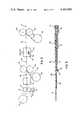
- FIG. 1is a schematic fragmentary sectional view of a laminate in accordance with the present invention.
- FIG. 2is a schematic representation of the process of the present invention.
- FIG. 3is a schematic representation illustrating the state of preparation of the laminate at the various points of the process illustrated schematically in FIG. 2.
- FIG. 4is a schematic perspective illustrating a typical automotive product utilizing the laminate of the present invention.
- the decorative laminate 10is illustrated schematically and comprises a base layer 12 that is prepared from a thermo formable resin film.
- the base layer 12is preferably prepared from a non-oriented film selected from the group consisting of amorphous polyester resins, polycarbonate resins, substituted and unsubstituted vinyl polymers, and their copolymers. More particularly, the amphorous polyesters may include polyethylene terephthalate, the polycarbonates may include acrylonitrile-butadiene-styrene resins, the vinyl polymers may include polyvinylchloride homo- or copolymers as well as other commercially available vacuum formable or thermo-formable materials.
- a preferred material for base layer 12comprises a polyethylene terephthalate sold by Allied Chemical Corporation, known as "Petra.”
- the inventionhowever is not limited to this later material, so long as the base layer is substantially non-oriented, that is to say, has not been previously mechanically treated, to enhance rigidity and "memory.”
- Base layer 12may be provided in a variety of thicknesses, depending upon the specific application for the resulting laminate, however, in the instance where an automotive laminate is contemplated, that is to be formed by injection molding as described hereinafter, base layer 12 preferably possesses a thickness ranging from about 3 mils to about 8 mils, and more specifically made be utilized at a thickness of 5 mils.
- Base layer 12is provided on both of its surfaces with tightly adherent, reflective metal coatings 14 and 16. While metal coatings 14 and 16 may be applied by a variety of well recognized techniques, it is preferable in the present invention that metal coatings 14 and 16 be applied by vapor deposition.
- the techniques of vapor depositionparticularly as utilized in connection with the preparation of aluminized polyester films, are well known, and are described, for example, in the Modern Plastics Encyclopedia (1970-1971), at pages 710 and following. For example, in the instance where aluminum is to be vapor deposited upon base layer 12, the aluminum (99+% pure) is held in a heated crucible in the form of pellets or the like, and is thereafter vaporized in a high vacuum chamber by resistance or induction heating.
- base layer 12comprises a continuous film, the running length of which is passed through the chamber so that one surface of the film is exposed to contact with the vaporized metal at a running rate sufficient to deposit a uniform layer of the metal onto the film, to a thickness of from 100 to 200 Angstroms.
- the opposite side of the filmmay be subjected to cooling by contact with a cooling cylinder, to effect the condensation of the aluminum on the metallized surface.
- Both of the metal coatings 14 and 16may be prepared by the foregoing method, to the thicknesses specified above, in accordance with one embodiment hereof.
- metal coatings 14 and 16 on both broad surfaces of base layer 12forms a sandwiching relationship therewith that obscures visual distortion that frequently results when base 12 is subjected to subsequent deformation by thermo forming techniques.
- Metal layers 14 and 16are applied in a particular sequence, that will be discussed later on with reference to the method of the present invention.
- an outer protective capping layer 18is provided, adhesively bonded to base layer 12, against metal coating 14. The exact sequence of application of capping layer 18 will be discussed later on with respect to the present method.
- Capping layer 18is prepared from a film that is treated to resist attack to ultra-violet light, and to be receptive to adhesive bonding.
- capping layer 18may receive surface treatments in a variety of ways, within the skill of the art, to provide both properties, such as, by corona discharge treatment, or by the application of known ultra-violet inhibitors and the like.
- ultra-violet inhibitors and stabilizersmay be utilized, among them compounds containing a benzotriazole or benzophenone nucleus. These materials are well known and commercially available, and may be selected for use in accordance with the skill of the art.
- Capping layer 18itself comprises a resin having particular resistance to ultra-violet radiation, and the corresponding capability to successfully undergo a thermo-forming operation.
- Layer 18may thus be prepared from a material selected from the group consisting of fluorinated vinyl-polymers, fluorinated polyolefins, and polyesters treated for resistance to ultra-violet radiation.
- capping layer 18may comprise a polyvinylfluoride, generally available and manufactured by DuPont under the name "Tedlar.”
- the capping layer 18may range in thickness from 1 to 2 mils, as it is provided to present a uniform and protective exterior surface to laminate 10.
- Capping layer 18is adhesively bonded to metal coating 14 by a pressure and heat sensitive elastomeric adhesive coating 20.
- Adhesive coating 20is resistant to attack by ultra-violet radiation and is harmless with respect to metal coating 14, and thus possesses favorable qualities lacking in the adhesives utilized in the prior art. As noted earlier, prior art adhesives tend to attack the metal layer and to cause its deterioration, and, by virtue of their instability in contact with ultra-violet light, tend to deteriorate unilaterally, and to allow delamination and other surface discontinuities to appear in the laminate over a short period of time.
- the adhesive coating 20may be a composition such as a silicone resin or an appropriate acrylic polymer, and is preferably the former.
- the adhesive coating 20may comprise homopolymers and copolymers of siloxane resins, such as those commercially manufactured by the General Electric Company, and others.
- compositions of adhesive coating 20,preferably contain a polymerization ccatalyst in amount that ranges from about 2% to about 6% by weight of the adhesive resin solids.
- the provision of the catalyst within this rangeis particularly advantageous, as it confers a partial cure to the adhesive that promotes improved bonding and stability of the adhesive after its application and disposition between capping layer 18 and metal coating 14, that resists distortion and resulting surface discontinuities during subsequent thermo-forming operations.
- One of the problems that has attended the use of various adhesives, particularly in contact with the metal layer of reflective laminateshas been the tendency of the adhesive, not only to attack the metal layer, but to undesirably migrate during subsequent thermo-forming.
- the present adhesive compositionsneither attack the metal layer nor migrate in such manner, and permit the formation of faithfully uniform, thermo-formed products, having retained, improved brilliance and reflectivity.
- a variety of polymerization catalystsmay be utilized in the compositions of adhesive coating 20, among them benzoyl peroxide, substituted benzoyl peroxide, amino-substituted compounds and silicone compounds.
- a preferred catalystcomprises an amino-substituted silane, such as gamma aminopropyl triethoxysilane.
- Adhesive coating 20is preferably applied to the surface of capping layer 18 that is to be bonded to metal coating 14, prior to the bonding thereof. The exact procedure associated with the application of adhesive coating 20, will be discussed with reference to the method of the present invention, later on. Preferably, adhesive coating 20 is applied to a dry thickness ranging from about 0.3 mils to about 0.8 mils, and particularly may be applied to a thickness ranging from 0.35 mils to 0.4 mils.
- metal coatings 14 and 16may be prepared from a variety of metals well known for imparting highly reflective corrosion and abrasion resistant surfaces.
- such metalsmay comprise chromium, alloys of chromium, nickel, nickel and chromium alloys such as Nichrome, iron, alloys of iron and chromium, stainless steel, aluminum, alloys of aluminum and others.
- the metal applied to form metal coatings 14 and 16comprises aluminum.
- backing layer 22may be prepared as a sheet or the like from a variety of resins, including various polyolefins, vinyl polymers and copolymers, polycarbonates, acrylic polymers and copolymers, and other materials capable of undergoing a thermo-forming operation.
- backing layer 22may be prepared from polyvinylchloride homo- and co-polymers, polyethylene, its copolymers and interpolymers, acrylonitrile-butadiene-styrene copolymers, and suitable mixtures thereof.
- backing layer 22comprises an ion-linked and modified ethylene interpoloymer, known commercially as "Surlyn.”
- Backing layer 22may vary in thickness, and, for example, may have a thickness of 20 mils, when provided for thermo-forming and subsequent injection molding for exterior automotive application.
- additional resinous materialeither identical to or variant but compatible with the composition of backing layer 22 may be laminated to the free surface thereof, or injection molded into association therewith by processes described further, later on.
- a method for preparing the present laminatescomprises first applying a metal coating on one surface of base layer 12, adhesively bonding capping layer 18 to the metallized surface provided, for example, by metal coating 14, and thereafter applying a second metal coating 16 to the uncoated free surface of base layer 12.
- the resulting laminate 10may optionally include a backing layer 22 that is subsequently applied by lamination techniques known in the art, including extrusion lamination, and the like.
- the first step of the present methodcomprises the deposition of metal coating 14 on one surface of base layer 12.
- base layer 12is disposed in an extended strip of varying widths, maintained on a roll, and is continually fed through a vacuum deposition chamber, in the manner described earlier, to provide a metallized surface on one side of the film strip.
- the one-sided metallized strip of base layer 12is gathered by a take up reel, not shown, and is stored in this condition for further processing in accordance herewith.
- the foregoing treatmentis performed in accordance with well known conventional industry standards, and a specific illustration thereof is not believed to be necessary.
- the next stepcomprises application of adhesive coating 20 to one surface of the film defining capping layer 18.
- capping layer 18may be paid out from a continuous roll 24 to provide a strip of material for continuous adhesive coating.
- Capping layer 18then passes through an adhesive coater where a regulated amount of adhesive composition is applied to the lower surface of layer 18, such as, for example, by the schematic assembly 26 illustrated herewith.
- assembly 26may comprise a trough having a quantity of adhesive compositions therein, a dip roll 30 that initially picks up the adhesive composition and relays it to a transfer roll 32, for application to the surface of capping layer 18.
- Proper coating pressuremaybe provided by a squeeze roll 34, so that a uniform coating 20 results.
- the coated layer 18maybe exposed to heat to dry adhesive coating 20, by passage through a drying tunnel 36, where heat is applied by forced air impinging on the wet surface. Drying may take place at a temperature on the order of about 240° F. with the coated layer 18 travelling at a speed of, for example, 70 feet per minute. Naturally, the foregoing parameters are illustrative only.
- the resulting composite layer 38is now ready for further processing in accordance with the present method.
- the next step in the processcomprises the adhesive bonding of composite capping layer 38 with the base layer 12 previously coated on one side with a metal coating such as metal coating 14.
- a metal coatingsuch as metal coating 14.
- the application of coating 14is conventional and is not illustrated schematically herein. Accordingly, a pay out reel 40 bearing the base layer 12 having the first metal coating 14 thereon, hereinafter referred to as first composite base layer 42 is brought into contact with the adhesive coated surface of composite capping layer 38, with its metal coated surface disposed thereagainst.
- adhesive coating 20is dry, however, the bonding of coating 14 to coating 20 may take place under pressure alone, as coating 20, noted earlier, is pressure sensitive. Alternatively, bonding may take place under combined heat and pressure, and these latter conditions are preferred. As illustrated in FIG.
- composite layers 38 and 42maybe bonded by passage between pressure rollers 44 and 46, which may likewise be heated to impart both heat and pressure to the materials.
- bondingmay take place at temperatures ranging from about 140° to 150° F., and pressures ranging from about 30 to about 60 psi.
- the resulting capped, metallized base 48consists essentially of four discrete layers, namely, capping layer 18, adhesive coating 20, metal coating 14 and base layer 12.
- Metallized base 48is thereafter coated on the free surface of base layer 12, with a second reflective metal coating 16, by feeding base 48 through a conventional vacuum metalization chamber schematically illustrated at 50.
- a quantity of metal in pelletized form within a container such as crucible 52is heated, such as by inductive heating means 54 to cause a fine layer of metal to deposit on the adjacent side of base 48, whereby layer 16 is formed.
- Layer 16 like layer 14maybe formed to a thickness of from 100 to 200 Angstroms, and the resulting product emerging from chamber 50 will comprise the preliminary laminated structure 56 that is the essence of the present invention.
- a backing layer 22 disposed on a similar pay out reel 58may be bonded to the free surface of metal coating 16, of laminated structure 56, by conventional techniques, including, as illustrated, passage through heated pressure rollers 60 and 62. While bonding by heat and pressure is illustrated schematically herein, it is to be understood, as discussed earlier, that the bonding of backing layer 22 to laminated structure 56 may be performed by other laminating techniques known in the art, within the scope of the present invention.
- the product exiting from rollers 60 and 62comprises laminate 10, illustrated in FIG. 1.
- FIG. 3a schematic cross-sectional illustration of the various layers coated and otherwise combined in accordance with the present method is provided, to illustrate the manner in which the respective layers are accumulated and brought together.
- the left hand portion of the figureshows capping layer 18 both before and after application of adhesive coating 20, and the resulting composite capping layer 38 produced thereby.
- first composite base layer 42 and its components, metal coating 14 and base layer 12are illustrated being brought together with composite capping layer 38, to form the multi-layered capped, metallized base 48.
- metallized base 48is shown after vacuum deposition of metal coating 16 on the free surface of base layer 12, to form preliminary laminated structure 56, and the final laminate 10 is shown to result from the bonding of backing layer 22 to the free surface of metal coating 16.
- bumper panel 64comprises a segment of laminate 10 that has been heated and molded by thermo forming techniques, to assume the three dimensional, curved shaped illustrated.
- the thermo forming operation per sedoes not form a part of the present invention, and is accordingly not illustrated herein.
- a precut segment of laminate 10, of a size sufficient to form the contoured part illustrated in FIG. 4,is placed in a heated die cavity, where either heat and vacuum or die pressure forces the laminate 10 to assume the configuration illustrated.
- the formed laminatemaybe placed in an injection molding cavity, where it serves as one of the surfaces against which a quantity of moldable resin is injected, in accordance with known techniques and parameters.
- the molded articleis permitted to cool and solidify.
- the male mold segmentis retracted, and the excess material from the article is trimmed and removed.
- the injection molded articleis removed from the female die, and the formation of the product such as bumper panel 64 is complete.
- panel 64is illustrated with a line of demarcation between backing layer 22 and the resinous substrate 66, to emphasize the quantity of resin that is frequently added by the final injection molding of the article.
- the amount of resin utilized in the addition of substrate 66may vary in accordance with manufacturing requirements and specific applications, and the present invention is not to be construed by way of limitation to the present illustrations.
- the present laminate and associated method of preparationmay be utilized for the production of a variety of products, including, without limitation, the preparation of a transfer sheet comprising a conventional carrier having a release coating disposed thereon, to which the outer surface of capping layer 18 may be releasably bound.
- the transfer sheetwould preferably comprise the preliminary laminated structure 56, identified in FIG. 3, which might optionally bear an appropriate adhesive coating, not shown herein, on the free metallized surface of metal coating 16.
- the foregoingis illustrative of a variant embodiment and utility of the present invention.
Landscapes
- Laminated Bodies (AREA)
Abstract
Description
Claims (18)
Priority Applications (1)
| Application Number | Priority Date | Filing Date | Title |
|---|---|---|---|
| US06/314,314US4403004A (en) | 1981-10-23 | 1981-10-23 | Sandwich metalized resin laminate |
Applications Claiming Priority (1)
| Application Number | Priority Date | Filing Date | Title |
|---|---|---|---|
| US06/314,314US4403004A (en) | 1981-10-23 | 1981-10-23 | Sandwich metalized resin laminate |
Publications (1)
| Publication Number | Publication Date |
|---|---|
| US4403004Atrue US4403004A (en) | 1983-09-06 |
Family
ID=23219461
Family Applications (1)
| Application Number | Title | Priority Date | Filing Date |
|---|---|---|---|
| US06/314,314Expired - Fee RelatedUS4403004A (en) | 1981-10-23 | 1981-10-23 | Sandwich metalized resin laminate |
Country Status (1)
| Country | Link |
|---|---|
| US (1) | US4403004A (en) |
Cited By (43)
| Publication number | Priority date | Publication date | Assignee | Title |
|---|---|---|---|---|
| US4722818A (en)* | 1984-03-20 | 1988-02-02 | The Standard Products Company | Method for making an elongated composite article |
| US4743477A (en)* | 1987-03-24 | 1988-05-10 | Beaver Warren R | Optical novelty simulating a containerized rainbow |
| US4868021A (en)* | 1987-10-07 | 1989-09-19 | The Standard Products Company | Molded trim with bright insert |
| DE4022737A1 (en)* | 1989-07-19 | 1991-01-24 | Toyoda Gosei Kk | Ornamental part for motor vehicles - has metal layer on plastic base, transparent protective layer consisting of UV absorber-contg. filter layer and hard surface layer |
| EP0417797A3 (en)* | 1989-09-14 | 1991-08-14 | Lothar Trier | Corrosion-protected trim moulding |
| US5753349A (en)* | 1994-04-04 | 1998-05-19 | Novavision, Inc. | Document having security image and composite sheet and method for forming |
| US5763024A (en)* | 1995-02-28 | 1998-06-09 | Transfer Print Foils, Inc. | Trim component including a metalized polyester film and substrate having curled edges |
| US5897937A (en)* | 1993-01-16 | 1999-04-27 | Saint Gobain Vitrage | Automobile glass pane adapted for bonding to a window frame and a method for the production thereof |
| US5916643A (en)* | 1987-03-27 | 1999-06-29 | Avery Dennison Corporation | Dry paint transfer-laminated body panels having deep-draw high DOI automotive paint coat |
| WO1999040770A1 (en)* | 1998-02-04 | 1999-08-12 | Stork Screens B.V. | Method of fabricating a support provided with shielding against interfering radiation, and shielding material |
| US6287672B1 (en) | 1999-03-12 | 2001-09-11 | Rexam, Inc. | Bright metallized film laminate |
| US6306242B1 (en)* | 1997-10-10 | 2001-10-23 | Peter J. Dronzek | Techniques for labeling of plastic, glass or metal containers or surfaces with polymeric labels |
| US20020009594A1 (en)* | 1998-12-15 | 2002-01-24 | Guardian Automotive Trim, Inc. | Extruded automotive trim and method of making same |
| US20020036368A1 (en)* | 1997-12-31 | 2002-03-28 | Textron Systems Corporation | Metallized sheeting, composites, and methods for their formation |
| US6551432B1 (en) | 1987-03-27 | 2003-04-22 | Avery Dennison Corporation | Dry paint transfer process and product |
| US6579397B1 (en) | 1987-03-27 | 2003-06-17 | Avery Dennison Corporation | Dry paint transfer process for making deep draw high DOI automotive body panels |
| US6602591B1 (en)* | 1998-12-15 | 2003-08-05 | Guardian Automotive Trim, Inc. | Automotive trim with clear top coat and method of making same |
| US20030170460A1 (en)* | 1999-10-13 | 2003-09-11 | John Sienkiewicz | Extruded automotive trim and method of making same |
| US20030190485A1 (en)* | 2002-03-26 | 2003-10-09 | Hirotsugu Takatsuki | Metallically decorated sheet and metallically decorated sheet intermediate |
| DE10233120A1 (en)* | 2002-07-20 | 2004-02-05 | Eichler Pulverbeschichtung Gmbh | Universal decorative surface coating for semi-finished products, e.g. aluminum bars, comprises conversion layer, levelling varnish, coupling layer, metallized layer and topcoat varnish |
| US6702343B1 (en) | 2002-11-02 | 2004-03-09 | William S. Stull | Automotive grille |
| US20040101692A1 (en)* | 2002-11-27 | 2004-05-27 | Mizuno Sei-No-Suke | Sparkling laminate film and sparkling shaped article |
| US20040219366A1 (en)* | 2003-05-02 | 2004-11-04 | Johnson John R. | Bright formable metalized film laminate |
| US20050023863A1 (en)* | 2002-11-02 | 2005-02-03 | Stull William S. | Automotive grille |
| US6858287B2 (en) | 2001-08-10 | 2005-02-22 | Soliant Llc | Formable bright film having discontinuous metallic layers |
| US20050182167A1 (en)* | 2001-03-05 | 2005-08-18 | Goodson Raymond L. | Fire-resistant architectural resin materials |
| US20050241759A1 (en)* | 2001-03-05 | 2005-11-03 | 3-Form | Laminate structure with polycarbonate sheets and method of making |
| US20060019089A1 (en)* | 2004-07-26 | 2006-01-26 | Npa Coatings, Inc. | Method for applying a decorative metal layer |
| EP1785268A1 (en)* | 2005-11-12 | 2007-05-16 | Hueck Folien Ges.m.b.H | Decorative sheet |
| US20080085402A1 (en)* | 2006-10-09 | 2008-04-10 | Leininger Marshall E | Method for applying a decorative layer and protective coating |
| US7550057B1 (en) | 2004-04-09 | 2009-06-23 | 3Form, Inc. | Architectural laminate panel with embedded compressible objects and methods for making the same |
| US20090197058A1 (en)* | 2007-05-08 | 2009-08-06 | 3Form, Inc. | Multivariate color system with texture application |
| US20090250136A1 (en)* | 2008-04-07 | 2009-10-08 | Illinois Tool Works Inc. | Corrosion resistant sheet metal jacketing |
| US20100289187A1 (en)* | 2009-05-15 | 2010-11-18 | Samsung Electronics Co., Ltd | Film for insert injection molding and insert injection molding method using the same |
| CN101124082B (en)* | 2004-06-11 | 2011-12-28 | 3-福姆有限公司 | Fire-resistant architectural resin materials |
| US20120052314A1 (en)* | 2001-11-30 | 2012-03-01 | Sabic Innovative Plastics Ip B.V. | Multilayer articles comprising resorcinol arylate polyester and method for making thereof |
| US20120091625A1 (en)* | 2009-03-23 | 2012-04-19 | Paolo Peruzza | Film for production of composite material artefacts, production method of said film and production method of composite material artefacts using said film |
| US8241714B2 (en) | 2004-09-01 | 2012-08-14 | 3Form, Inc. | Architectural panels with objects embedded in resin interlayer |
| USD691289S1 (en) | 2012-09-05 | 2013-10-08 | 3Form, Inc. | Panel with cut and aligned thatch interlayer |
| EP2803753A1 (en) | 2013-05-13 | 2014-11-19 | Grendene S/A | Soft and flexible metallized polymeric article, method for producing the same, footwear with soft and flexible metallized polymeric component, method for producing footwear. |
| US20160089850A1 (en)* | 2014-09-30 | 2016-03-31 | Yamaha Fine Technologies Co., Ltd. | Decoration panel and method for manufacturing decoration panel |
| RU2603621C2 (en)* | 2011-07-15 | 2016-11-27 | Хуек Фолиен Гезелльшафт М.Б.Х. | Flat carrier and method of making flat carrier |
| EP3733749A1 (en) | 2019-05-02 | 2020-11-04 | Hueck Folien Gesellschaft m.b.H. | Metallized film |
Citations (6)
| Publication number | Priority date | Publication date | Assignee | Title |
|---|---|---|---|---|
| US3152950A (en)* | 1954-06-03 | 1964-10-13 | Minnesota Mining & Mfg | Protective reflective film |
| US3720567A (en)* | 1971-02-09 | 1973-03-13 | Glass Lab Co | Light reflective composite molding |
| US3811989A (en)* | 1972-05-15 | 1974-05-21 | Creators Ltd | Decorative trim strips |
| US4101698A (en)* | 1975-07-14 | 1978-07-18 | Avery International Corp. | Elastomeric reflective metal surfaces |
| US4235949A (en)* | 1978-07-27 | 1980-11-25 | Voplex Corporation | Non-wrinkling automotive trim strip |
| US4275099A (en)* | 1979-11-05 | 1981-06-23 | Dunmore Corporation | Metalized polyester resin laminate |
- 1981
- 1981-10-23USUS06/314,314patent/US4403004A/ennot_activeExpired - Fee Related
Patent Citations (6)
| Publication number | Priority date | Publication date | Assignee | Title |
|---|---|---|---|---|
| US3152950A (en)* | 1954-06-03 | 1964-10-13 | Minnesota Mining & Mfg | Protective reflective film |
| US3720567A (en)* | 1971-02-09 | 1973-03-13 | Glass Lab Co | Light reflective composite molding |
| US3811989A (en)* | 1972-05-15 | 1974-05-21 | Creators Ltd | Decorative trim strips |
| US4101698A (en)* | 1975-07-14 | 1978-07-18 | Avery International Corp. | Elastomeric reflective metal surfaces |
| US4235949A (en)* | 1978-07-27 | 1980-11-25 | Voplex Corporation | Non-wrinkling automotive trim strip |
| US4275099A (en)* | 1979-11-05 | 1981-06-23 | Dunmore Corporation | Metalized polyester resin laminate |
Cited By (75)
| Publication number | Priority date | Publication date | Assignee | Title |
|---|---|---|---|---|
| US4722818A (en)* | 1984-03-20 | 1988-02-02 | The Standard Products Company | Method for making an elongated composite article |
| US4743477A (en)* | 1987-03-24 | 1988-05-10 | Beaver Warren R | Optical novelty simulating a containerized rainbow |
| US6551432B1 (en) | 1987-03-27 | 2003-04-22 | Avery Dennison Corporation | Dry paint transfer process and product |
| US6649003B1 (en) | 1987-03-27 | 2003-11-18 | Avery Dennison Corporation | Dry paint transfer lamination process for making high DOI automotive body panels |
| US20040123941A1 (en)* | 1987-03-27 | 2004-07-01 | Spain Patrick L. | Dry paint transfer-lamination process for making high doi automotive body panels |
| US5916643A (en)* | 1987-03-27 | 1999-06-29 | Avery Dennison Corporation | Dry paint transfer-laminated body panels having deep-draw high DOI automotive paint coat |
| US6966962B2 (en) | 1987-03-27 | 2005-11-22 | Avery Dennison Corporation | Dry paint transfer-lamination process for making high DOI automotive body panels |
| US6984280B2 (en) | 1987-03-27 | 2006-01-10 | Avery Dennison Coporation | Dry paint transfer process for making deep-draw high doi automotive body panels |
| US20040123942A1 (en)* | 1987-03-27 | 2004-07-01 | Spain Patrick L. | Dry paint transfer process for making deep-draw high doi automotive body panels |
| US6838130B1 (en) | 1987-03-27 | 2005-01-04 | Avery Dennison Corporation | Dry paint transfer process and product |
| US6579397B1 (en) | 1987-03-27 | 2003-06-17 | Avery Dennison Corporation | Dry paint transfer process for making deep draw high DOI automotive body panels |
| US6835267B1 (en) | 1987-03-27 | 2004-12-28 | Avery Dennison Corporation | Dry paint transfer process and product |
| US4868021A (en)* | 1987-10-07 | 1989-09-19 | The Standard Products Company | Molded trim with bright insert |
| DE4022737A1 (en)* | 1989-07-19 | 1991-01-24 | Toyoda Gosei Kk | Ornamental part for motor vehicles - has metal layer on plastic base, transparent protective layer consisting of UV absorber-contg. filter layer and hard surface layer |
| EP0417797A3 (en)* | 1989-09-14 | 1991-08-14 | Lothar Trier | Corrosion-protected trim moulding |
| US5897937A (en)* | 1993-01-16 | 1999-04-27 | Saint Gobain Vitrage | Automobile glass pane adapted for bonding to a window frame and a method for the production thereof |
| US5753349A (en)* | 1994-04-04 | 1998-05-19 | Novavision, Inc. | Document having security image and composite sheet and method for forming |
| US5763024A (en)* | 1995-02-28 | 1998-06-09 | Transfer Print Foils, Inc. | Trim component including a metalized polyester film and substrate having curled edges |
| US6306242B1 (en)* | 1997-10-10 | 2001-10-23 | Peter J. Dronzek | Techniques for labeling of plastic, glass or metal containers or surfaces with polymeric labels |
| US6455138B1 (en) | 1997-12-31 | 2002-09-24 | Textron System Corporation | Metallized sheeting, composites, and methods for their formation |
| US20020036368A1 (en)* | 1997-12-31 | 2002-03-28 | Textron Systems Corporation | Metallized sheeting, composites, and methods for their formation |
| US6761793B2 (en) | 1997-12-31 | 2004-07-13 | Textron Systems Corporation | Method for forming a metallized composite |
| WO1999040770A1 (en)* | 1998-02-04 | 1999-08-12 | Stork Screens B.V. | Method of fabricating a support provided with shielding against interfering radiation, and shielding material |
| US7005103B2 (en) | 1998-12-15 | 2006-02-28 | Guardian Automotive Trim, Inc. | Method of making a colored automotive trim product |
| US20020009594A1 (en)* | 1998-12-15 | 2002-01-24 | Guardian Automotive Trim, Inc. | Extruded automotive trim and method of making same |
| US6602591B1 (en)* | 1998-12-15 | 2003-08-05 | Guardian Automotive Trim, Inc. | Automotive trim with clear top coat and method of making same |
| US6565955B2 (en) | 1999-03-12 | 2003-05-20 | Soliant Llc | Bright indium-metallized formable film laminate |
| US6287672B1 (en) | 1999-03-12 | 2001-09-11 | Rexam, Inc. | Bright metallized film laminate |
| US20030170460A1 (en)* | 1999-10-13 | 2003-09-11 | John Sienkiewicz | Extruded automotive trim and method of making same |
| US7195727B2 (en) | 1999-10-13 | 2007-03-27 | Guardian Industries Corp. | Extruded automotive trim and method of making same |
| US7691470B2 (en) | 2001-03-05 | 2010-04-06 | 3Form | Laminate structure with polycarbonate sheets |
| US7303810B2 (en)* | 2001-03-05 | 2007-12-04 | 3Form, Inc. | Fire-resistant architectural resin materials |
| US20050182167A1 (en)* | 2001-03-05 | 2005-08-18 | Goodson Raymond L. | Fire-resistant architectural resin materials |
| US20050241759A1 (en)* | 2001-03-05 | 2005-11-03 | 3-Form | Laminate structure with polycarbonate sheets and method of making |
| US6858287B2 (en) | 2001-08-10 | 2005-02-22 | Soliant Llc | Formable bright film having discontinuous metallic layers |
| US20120052314A1 (en)* | 2001-11-30 | 2012-03-01 | Sabic Innovative Plastics Ip B.V. | Multilayer articles comprising resorcinol arylate polyester and method for making thereof |
| USD621068S1 (en) | 2002-03-01 | 2010-08-03 | 3Form, Inc. | Architectural panel with thatch reed design |
| US20030190485A1 (en)* | 2002-03-26 | 2003-10-09 | Hirotsugu Takatsuki | Metallically decorated sheet and metallically decorated sheet intermediate |
| US7666497B2 (en)* | 2002-03-26 | 2010-02-23 | Japan Wavelock Co., Ltd. | Metallically decorated sheet and metallically decorated sheet intermediate |
| DE10233120A1 (en)* | 2002-07-20 | 2004-02-05 | Eichler Pulverbeschichtung Gmbh | Universal decorative surface coating for semi-finished products, e.g. aluminum bars, comprises conversion layer, levelling varnish, coupling layer, metallized layer and topcoat varnish |
| US6957837B2 (en) | 2002-11-02 | 2005-10-25 | Stull William S | Automotive grille |
| US20050023863A1 (en)* | 2002-11-02 | 2005-02-03 | Stull William S. | Automotive grille |
| US6951356B1 (en)* | 2002-11-02 | 2005-10-04 | Stull William S | Automotive grille |
| US6702343B1 (en) | 2002-11-02 | 2004-03-09 | William S. Stull | Automotive grille |
| US20040101692A1 (en)* | 2002-11-27 | 2004-05-27 | Mizuno Sei-No-Suke | Sparkling laminate film and sparkling shaped article |
| US20040219366A1 (en)* | 2003-05-02 | 2004-11-04 | Johnson John R. | Bright formable metalized film laminate |
| US20050175843A1 (en)* | 2003-05-02 | 2005-08-11 | Johnson John R. | Bright formable metalized film laminate |
| US7550057B1 (en) | 2004-04-09 | 2009-06-23 | 3Form, Inc. | Architectural laminate panel with embedded compressible objects and methods for making the same |
| WO2005123824A3 (en)* | 2004-06-11 | 2007-03-29 | Form Inc 3 | Fire-resistant architectural resin materials |
| CN101124082B (en)* | 2004-06-11 | 2011-12-28 | 3-福姆有限公司 | Fire-resistant architectural resin materials |
| US7297397B2 (en) | 2004-07-26 | 2007-11-20 | Npa Coatings, Inc. | Method for applying a decorative metal layer |
| US20060019089A1 (en)* | 2004-07-26 | 2006-01-26 | Npa Coatings, Inc. | Method for applying a decorative metal layer |
| US8241714B2 (en) | 2004-09-01 | 2012-08-14 | 3Form, Inc. | Architectural panels with objects embedded in resin interlayer |
| EP1785268A1 (en)* | 2005-11-12 | 2007-05-16 | Hueck Folien Ges.m.b.H | Decorative sheet |
| US20100035032A1 (en)* | 2005-11-12 | 2010-02-11 | Hueck Folien Ges.M.B.H | Decorative foil |
| WO2007054343A3 (en)* | 2005-11-12 | 2007-09-07 | Hueck Folien Gmbh | Decorative foil |
| US20080085402A1 (en)* | 2006-10-09 | 2008-04-10 | Leininger Marshall E | Method for applying a decorative layer and protective coating |
| US20110226424A1 (en)* | 2007-05-08 | 2011-09-22 | 3Form, Inc. | Multivariate color system with texture application |
| US8617695B2 (en) | 2007-05-08 | 2013-12-31 | 3Form, Inc. | Multivariate color system with texture application |
| US9348065B2 (en) | 2007-05-08 | 2016-05-24 | 3Form, Llc | Multivariate color system with texture application |
| US8157942B1 (en) | 2007-05-08 | 2012-04-17 | Willham John E C | Multivariate color system with texture application |
| US8268106B2 (en) | 2007-05-08 | 2012-09-18 | 3Form, Inc. | Multivariate color system with texture application |
| US8182903B2 (en) | 2007-05-08 | 2012-05-22 | 3Form, Inc. | Multivariate color system with texture application |
| US20090197058A1 (en)* | 2007-05-08 | 2009-08-06 | 3Form, Inc. | Multivariate color system with texture application |
| US20090250136A1 (en)* | 2008-04-07 | 2009-10-08 | Illinois Tool Works Inc. | Corrosion resistant sheet metal jacketing |
| US10208885B2 (en)* | 2008-04-07 | 2019-02-19 | Illinois Tool Works Inc. | Corrosion resistant sheet metal jacketing |
| US20120091625A1 (en)* | 2009-03-23 | 2012-04-19 | Paolo Peruzza | Film for production of composite material artefacts, production method of said film and production method of composite material artefacts using said film |
| US20100289187A1 (en)* | 2009-05-15 | 2010-11-18 | Samsung Electronics Co., Ltd | Film for insert injection molding and insert injection molding method using the same |
| RU2603621C2 (en)* | 2011-07-15 | 2016-11-27 | Хуек Фолиен Гезелльшафт М.Б.Х. | Flat carrier and method of making flat carrier |
| USD691289S1 (en) | 2012-09-05 | 2013-10-08 | 3Form, Inc. | Panel with cut and aligned thatch interlayer |
| EP2803753A1 (en) | 2013-05-13 | 2014-11-19 | Grendene S/A | Soft and flexible metallized polymeric article, method for producing the same, footwear with soft and flexible metallized polymeric component, method for producing footwear. |
| US20160089850A1 (en)* | 2014-09-30 | 2016-03-31 | Yamaha Fine Technologies Co., Ltd. | Decoration panel and method for manufacturing decoration panel |
| US10166739B2 (en)* | 2014-09-30 | 2019-01-01 | Yamaha Fine Technologies Co., Ltd. | Decoration panel and method for manufacturing decoration panel |
| EP3733749A1 (en) | 2019-05-02 | 2020-11-04 | Hueck Folien Gesellschaft m.b.H. | Metallized film |
| WO2020221753A1 (en) | 2019-05-02 | 2020-11-05 | Hueck Folien Gesellschaft M.B.H. | Metallized film |
Similar Documents
| Publication | Publication Date | Title |
|---|---|---|
| US4403004A (en) | Sandwich metalized resin laminate | |
| CA2365842C (en) | Bright metallized film laminate | |
| US6858287B2 (en) | Formable bright film having discontinuous metallic layers | |
| CA2099600C (en) | Surfacing film with thermoformable carrier layer | |
| US6761793B2 (en) | Method for forming a metallized composite | |
| CA2266873C (en) | Film finishing system with design option | |
| US10099462B2 (en) | Releasable polyester high gloss metal transfer film | |
| GB2039791A (en) | Delamination resistant multilayer metal/polymer composites | |
| WO1995023688A1 (en) | Vehicle part having weather sealed mirror finish decorative portion integral therewith | |
| US5763024A (en) | Trim component including a metalized polyester film and substrate having curled edges | |
| CA1210681A (en) | Sandwich metalized composite laminate | |
| US20020192440A1 (en) | Bright tin-metallized formable film laminate | |
| CA2333795A1 (en) | Longitudinally stretched, vacuum vapour coated packaging films | |
| US20040101692A1 (en) | Sparkling laminate film and sparkling shaped article | |
| JPH11208196A (en) | Metal thin film transfer foil for simultaneous forming | |
| JP7284917B2 (en) | Coating Substitute Films, Composite Films, Laminated Metal Sheets, Processed Products and Molded Products | |
| JP3704421B2 (en) | Corrosion-resistant metallized film for PVC steel sheet | |
| JP2527808Y2 (en) | Synthetic resin laminated film for molding | |
| MXPA00006517A (en) | Metallized sheeting, composites, and methods for their formation | |
| HU209158B (en) | Method for joining surfaces of metal and plastic workpieces | |
| JPH11123739A (en) | Method for producing high gloss injection molded article and molded article thereof | |
| MXPA97001428A (en) | Adorno or aluminum molding reflec | |
| CA2025557A1 (en) | Fluoropolymer-metal laminates |
Legal Events
| Date | Code | Title | Description |
|---|---|---|---|
| AS | Assignment | Owner name:TRANSFER PRINT FOILS, INC., 9 COTTERS LANE, EAST B Free format text:ASSIGNMENT OF ASSIGNORS INTEREST.;ASSIGNORS:PARKER, HARRY A.;GREENMAN, JOSEPH;REEL/FRAME:003942/0721 Effective date:19811020 | |
| FEPP | Fee payment procedure | Free format text:SURCHARGE FOR LATE PAYMENT, PL 96-517 (ORIGINAL EVENT CODE: M176); ENTITY STATUS OF PATENT OWNER: LARGE ENTITY | |
| MAFP | Maintenance fee payment | Free format text:PAYMENT OF MAINTENANCE FEE, 4TH YEAR, PL 96-517 (ORIGINAL EVENT CODE: M170); ENTITY STATUS OF PATENT OWNER: LARGE ENTITY Year of fee payment:4 | |
| FEPP | Fee payment procedure | Free format text:PAYOR NUMBER ASSIGNED (ORIGINAL EVENT CODE: ASPN); ENTITY STATUS OF PATENT OWNER: LARGE ENTITY | |
| AS | Assignment | Owner name:MIDLANTIC NATIONAL BANK, 710 TURNPIKE ROAD, EAST B Free format text:SECURITY INTEREST;ASSIGNOR:TRANSFER PRINT FOILS, INC.;REEL/FRAME:005264/0776 Effective date:19900104 | |
| FEPP | Fee payment procedure | Free format text:MAINTENANCE FEE REMINDER MAILED (ORIGINAL EVENT CODE: REM.); ENTITY STATUS OF PATENT OWNER: LARGE ENTITY | |
| LAPS | Lapse for failure to pay maintenance fees | ||
| STCH | Information on status: patent discontinuation | Free format text:PATENT EXPIRED DUE TO NONPAYMENT OF MAINTENANCE FEES UNDER 37 CFR 1.362 | |
| FP | Lapsed due to failure to pay maintenance fee | Effective date:19910908 | |
| AS | Assignment | Owner name:ILLINOIS TOOL WORKS INC., ILLINOIS Free format text:ASSIGNMENT OF ASSIGNORS INTEREST;ASSIGNOR:TRANSFER PRINT FOILS, INC.;REEL/FRAME:012075/0198 Effective date:20010521 |