US4402641A - Self centering fastener - Google Patents
Self centering fastenerDownload PDFInfo
- Publication number
- US4402641A US4402641AUS06/238,718US23871881AUS4402641AUS 4402641 AUS4402641 AUS 4402641AUS 23871881 AUS23871881 AUS 23871881AUS 4402641 AUS4402641 AUS 4402641A
- Authority
- US
- United States
- Prior art keywords
- shank
- fastening element
- ribs
- webs
- element according
- Prior art date
- Legal status (The legal status is an assumption and is not a legal conclusion. Google has not performed a legal analysis and makes no representation as to the accuracy of the status listed.)
- Expired - Lifetime
Links
- 229920002994synthetic fiberPolymers0.000claimsabstractdescription3
- 230000015572biosynthetic processEffects0.000claimsdescription3
- 238000005452bendingMethods0.000description2
- 238000003780insertionMethods0.000description2
- 230000037431insertionEffects0.000description2
- 239000000463materialSubstances0.000description2
- 239000002184metalSubstances0.000description2
- 241000191291Abies albaSpecies0.000description1
- 238000004873anchoringMethods0.000description1
- 238000010276constructionMethods0.000description1
- 230000001419dependent effectEffects0.000description1
- 238000001746injection mouldingMethods0.000description1
- 238000003475laminationMethods0.000description1
- 238000004519manufacturing processMethods0.000description1
- 238000000034methodMethods0.000description1
Images

Classifications
- F—MECHANICAL ENGINEERING; LIGHTING; HEATING; WEAPONS; BLASTING
- F16—ENGINEERING ELEMENTS AND UNITS; GENERAL MEASURES FOR PRODUCING AND MAINTAINING EFFECTIVE FUNCTIONING OF MACHINES OR INSTALLATIONS; THERMAL INSULATION IN GENERAL
- F16B—DEVICES FOR FASTENING OR SECURING CONSTRUCTIONAL ELEMENTS OR MACHINE PARTS TOGETHER, e.g. NAILS, BOLTS, CIRCLIPS, CLAMPS, CLIPS OR WEDGES; JOINTS OR JOINTING
- F16B19/00—Bolts without screw-thread; Pins, including deformable elements; Rivets
- F16B19/002—Resiliently deformable pins
- F16B19/004—Resiliently deformable pins made in one piece
- F—MECHANICAL ENGINEERING; LIGHTING; HEATING; WEAPONS; BLASTING
- F16—ENGINEERING ELEMENTS AND UNITS; GENERAL MEASURES FOR PRODUCING AND MAINTAINING EFFECTIVE FUNCTIONING OF MACHINES OR INSTALLATIONS; THERMAL INSULATION IN GENERAL
- F16B—DEVICES FOR FASTENING OR SECURING CONSTRUCTIONAL ELEMENTS OR MACHINE PARTS TOGETHER, e.g. NAILS, BOLTS, CIRCLIPS, CLAMPS, CLIPS OR WEDGES; JOINTS OR JOINTING
- F16B21/00—Means for preventing relative axial movement of a pin, spigot, shaft or the like and a member surrounding it; Stud-and-socket releasable fastenings
- F16B21/06—Releasable fastening devices with snap-action
- F16B21/08—Releasable fastening devices with snap-action in which the stud, pin, or spigot has a resilient part
- F16B21/084—Releasable fastening devices with snap-action in which the stud, pin, or spigot has a resilient part with a series of flexible ribs or fins extending laterally from the shank of the stud, pin or spigot, said ribs or fins deforming predominantly in a direction parallel to the direction of insertion of the shank
- Y—GENERAL TAGGING OF NEW TECHNOLOGICAL DEVELOPMENTS; GENERAL TAGGING OF CROSS-SECTIONAL TECHNOLOGIES SPANNING OVER SEVERAL SECTIONS OF THE IPC; TECHNICAL SUBJECTS COVERED BY FORMER USPC CROSS-REFERENCE ART COLLECTIONS [XRACs] AND DIGESTS
- Y10—TECHNICAL SUBJECTS COVERED BY FORMER USPC
- Y10S—TECHNICAL SUBJECTS COVERED BY FORMER USPC CROSS-REFERENCE ART COLLECTIONS [XRACs] AND DIGESTS
- Y10S411/00—Expanded, threaded, driven, headed, tool-deformed, or locked-threaded fastener
- Y10S411/904—Fastener or fastener element composed of nonmetallic material
- Y10S411/908—Resinous material
- Y—GENERAL TAGGING OF NEW TECHNOLOGICAL DEVELOPMENTS; GENERAL TAGGING OF CROSS-SECTIONAL TECHNOLOGIES SPANNING OVER SEVERAL SECTIONS OF THE IPC; TECHNICAL SUBJECTS COVERED BY FORMER USPC CROSS-REFERENCE ART COLLECTIONS [XRACs] AND DIGESTS
- Y10—TECHNICAL SUBJECTS COVERED BY FORMER USPC
- Y10T—TECHNICAL SUBJECTS COVERED BY FORMER US CLASSIFICATION
- Y10T24/00—Buckles, buttons, clasps, etc.
- Y10T24/30—Trim molding fastener
- Y10T24/309—Plastic type
Definitions
- fastening elements of the type shownare already known (German disclosure letter No. 24 06 231). It serves to fasten an article to a workpiece provided with an aperture, e.g. a sheet metal plate.
- the lamellar flexible ribsmake possible an effective fastening of articles of different thicknesses to a holding element, in that dependent on the thickness of the article a corresponding lamellar rib grips beneath the edge of the aperture at the underside of the holding element, for instance, a sheet metal plate.
- the handling of such fastening elementsis extremely simple, because they only have to be forced or beaten into an aperture via their head. For this reason the field of application of such fastening elements also is extraordinarily wide and many-sided.
- the object of this inventionis fulfilled in accordance with the invention in that between adjacent rows of lamellar ribs an axially extending rib is respectively formed in a circumferential direction integrally with the shank which is provided with at least one axial guide surface adapted to be brought into contact with the aperture wall of a workpiece.
- the lamellar ribsare the portions of the fastening element projecting farthest in the radial direction and a recess is respectively arranged between adjacent rows of lamellar ribs.
- the shankWith the aid of such axial ribs, which are preferably disposed diametrically with respect to the shank axis, the shank may be centered upon insertion of the fastening element into an aperture of a workpiece so that upon engagement with the aperture wall all the lamellar ribs are deformed uniformly and thus are uniformly loaded. Excessive loading and the danger of individual ones of the laminations breaking away are thus avoided.
- the fastening element according to the instant inventionthe shank is arranged centrically in the fastening aperture and an absolutely safe anchoring of the fastening element is obtained.
- the axial ribto radially taper towards the free end of the shank.
- the shank and the axial ribs integrally formed therewithto be of a double-T-shape cross sectional configuration with the lamellar ribs accommodated by the recesses between the transverse webs on either side of the longitudinal web but being at least in part freely movable with respect to the transverse webs.
- Such a constructionis simple to manufacture, i.e. by injection molding using relatively simple tools.
- such a shank configurationprovides for a safe guidance and centering of the shank in a workpiece aperture and as seen in the drawings, a lamellar rib having a substantially longer length.
- the transverse webs of the double-T-shape shankare slightly shorter than the width, and the spacing of the outsides of the transverse webs is slightly smaller than the length of the aperture.
- Such a shankmay be inserted into a rectangular aperture leaving a slight play with respect to the double-T-shape and ensures that the lamellar ribs are uniformly brought into engagement with the aperture wall on opposite sides and are thus uniformly deformed and loaded, i.e. both during the procedure of insertion and also afterwards.
- the transverse webs of the double-T-shape shankare tapered at the outer corners for the formation of the guide surfaces. It may indeed be imagined to provide the guide surfaces with a radius adapted to the radius of the fastening aperture in order to establish snug engagement with the aperture wall; as, however, the width of the guide surface is relatively small, it suffices also to design the guide surface to be planar.
- the shankin connection with the last mentioned embodiment provision is made in a further development of the invention for the shank to be reduced in cross section in the region of the ribs in the direction of the radial extension thereof. In this manner a substantial saving of plastic material may be obtained in the formation of the shank of the fastening element and the length of the ribs is increased.
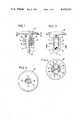
- FIG. 1shows a part-sectional side elevational view of the fastening element according to the invention.
- FIG. 2shows a side view of the fastening element according to FIG. 1.
- FIG. 3shows a sectional view of the fastening element according to FIG. 1 taken on line 3--3.
- FIG. 4shows a sectional view of the fastening element according to FIG. 2 taken on line 4--4.
- FIG. 5shows a side view partly in section of another embodiment of a fastening element according to the invention.
- FIG. 6shows a sectional view of the fastening element according to FIG. 5 taken on line 6--6.
- FIG. 7shows another side view of the fastening element according to FIG. 5.
- the clip type fastening element shown in FIGS. 1 to 4possesses a plate-shaped head 10 and a shank 11 extending axially from said head 10, which it will now be dealt with in more detail.
- the shank 11is provided with a double-T-shaped cross-sectional configuration over the greatest portion of its extension, as to be seen from FIG. 4.
- the longitudinal web 14is provided with rectangular recesses 15, 16 on the opposing longitudinal sides thereof which are for material saving purposes.
- radial flexible ribs 19are formed integrally with said web 14 between the transverse webs 12, 13.
- Each of the ribs of each roware axially spaced from each other.
- the ribs 19which are arranged in the form of a Christmas Tree® fastener have an approximately triangular cross-sectional configuration and in their inclination are slightly pointing towards the head 10.
- the lower five ribshave essentially the same axial width and radially extending length, while the upper two ribs are shaped to be clearly visibly shorter.
- the ribs 19are spaced from the facing side of the transverse webs 12, 13 through a certain distance as identified at 20 in order to permit a free bending deformation of the ribs 19 with respect to the shank 11 and the transverse webs 12, 13 thereof, respectively.
- the transverse webs 12, 13form axial ribs which are tapering upwards towards the head 10 and downwards as indicated at 21 and 22, respectively, in FIG. 2.
- a taper of the longitudinal webis provided also in the direction which is offset by 90° as indicated at 24.
- the transverse webs 12, 13 and the axial ribs formed thereby, respectively,are tapered at the outer corners, as indicated at 25.
- four diametrically opposed guide surfacesare formed which substantially conforms to the diameter of a circular fastening aperture, as indicated in FIG. 4 by the dotted line 26.
- the guide surfacescenter the shank 11 in the workpiece aperture 26 so that the flexible ribs 19 which by their radial extension thereby extend beyond the width of the aperture 26 are uniformly deformed and loaded.
- the connection of the shank 11 to the head 10may be recognized from FIG. 3.
- the shank 11possesses in cross section two parallel straight sides 27, 28 and two opposite arcuate sides 29, 30.
- FIGS. 5 to 7is intended for a rectangular workpiece aperture and possesses again a plate-shaped head 110 and a shank 111 extending axially thereof.
- the cross section of the shank, as shown in FIG. 6,is again double-T-shaped and thus comprises two transverse webs 112, 113 and one longitudinal web 114.
- On both longitudinal sides of the longitudinal web 114two rows 117, 118 of lamellar radially extending flexible ribs 119 are again formed integrally with said web the function of which is the same as the flexible ribs 19 as discussed according to FIGS. 1 to 4.
- Spaces 120are provided between the ribs 119 and the transverse webs 112, 113 in order to make possible a flexible bending of the ribs 119 with respect to the shank 111 and the webs 112, 113.
- transverse webs 112, 113 and outwardly facing surfaces thereof facing the aperture wall, respectively,are inserted into a rectangular aperture with slight play and thus serve centering purposes and to ensure a centered seating in the workpiece aperture.
- the ribs 119which are of a greater extension than the corresponding width of the fastening aperture are thereby again uniformly deformed and uniformly loaded on both sides so that the danger of breakage thereof during the introduction of the fastening element into the fastening aperture or while being seated therein is avoided.
- the shank 111is slightly tapered towards the free end thereof, as shown at 123, in order to facilitate the introduction into a fastening aperture.
Landscapes
- Engineering & Computer Science (AREA)
- General Engineering & Computer Science (AREA)
- Mechanical Engineering (AREA)
- Insertion Pins And Rivets (AREA)
- Connection Of Plates (AREA)
- Dowels (AREA)
Abstract
Description
Claims (8)
Applications Claiming Priority (2)
| Application Number | Priority Date | Filing Date | Title |
|---|---|---|---|
| DE3014745 | 1980-04-17 | ||
| DE19803014745DE3014745A1 (en) | 1980-04-17 | 1980-04-17 | ONE-PIECE FASTENING ELEMENT FROM PLASTIC (SELF-CENTERING TREE CLIP) |
Publications (1)
| Publication Number | Publication Date |
|---|---|
| US4402641Atrue US4402641A (en) | 1983-09-06 |
Family
ID=6100260
Family Applications (1)
| Application Number | Title | Priority Date | Filing Date |
|---|---|---|---|
| US06/238,718Expired - LifetimeUS4402641A (en) | 1980-04-17 | 1981-02-27 | Self centering fastener |
Country Status (6)
| Country | Link |
|---|---|
| US (1) | US4402641A (en) |
| BR (1) | BR8101548A (en) |
| DE (1) | DE3014745A1 (en) |
| ES (1) | ES257727Y (en) |
| FR (1) | FR2501808A1 (en) |
| GB (1) | GB2074688A (en) |
Cited By (55)
| Publication number | Priority date | Publication date | Assignee | Title |
|---|---|---|---|---|
| US4705442A (en)* | 1986-04-07 | 1987-11-10 | Trw Inc. | Quarter turn fastener |
| US4724628A (en)* | 1986-01-03 | 1988-02-16 | Schreiner Kevin E | Heel jewelry |
| USD295722S (en) | 1985-05-24 | 1988-05-17 | Nifco Inc. | Panel fastener or the like |
| USD295826S (en) | 1985-06-26 | 1988-05-24 | Nifco Inc. | Fastener or the like |
| USD295951S (en) | 1985-06-26 | 1988-05-31 | Nifco Inc. | Fastener or the like |
| US4776328A (en)* | 1986-04-15 | 1988-10-11 | Sulzer Brothers Limited | Bone nail and an instrument for implanting a bone nail |
| US4787795A (en)* | 1985-10-02 | 1988-11-29 | Trw United-Carr Gmbh | Push-in fastener |
| USD298801S (en) | 1985-09-26 | 1988-12-06 | Nifco Inc. | Panel fastener or the like |
| US4805370A (en)* | 1987-07-20 | 1989-02-21 | General Electric Company | Cabinet corner cap and method of assembly |
| US4867599A (en)* | 1987-10-15 | 1989-09-19 | Toyoda Gosei Co., Ltd. | Automotive column cover |
| US4938645A (en)* | 1989-05-30 | 1990-07-03 | Phillips Plastics Corporation | Tee tree fastener |
| US4981310A (en)* | 1988-12-16 | 1991-01-01 | Legris Sa | Device for fixing an element passing through a wall |
| US4993903A (en)* | 1989-11-16 | 1991-02-19 | Trw United Carr Gmbh & Co. | Plastic fastening element with flexible centering straps |
| US5039267A (en)* | 1989-05-30 | 1991-08-13 | Phillips Plastics Corporation | Tee tree fastener |
| US5261914A (en)* | 1987-09-02 | 1993-11-16 | Russell Warren | Surgical fastener |
| US5468108A (en)* | 1994-09-12 | 1995-11-21 | Illinois Tool Works Inc. | Spiral flex tree fastener |
| USD367420S (en) | 1994-12-12 | 1996-02-27 | Newcomer Charles H | Fastener |
| US5496141A (en)* | 1993-05-22 | 1996-03-05 | Moss Plastic Parts Limited | Article for insertion into an opening |
| AT1514U1 (en)* | 1996-08-01 | 1997-06-25 | Blum Gmbh Julius | DOWEL |
| US5669727A (en)* | 1991-12-12 | 1997-09-23 | Karner & Company Aktiebolag | Device for fixedly interconnecting two parts of a clothes hanger |
| US5672038A (en)* | 1995-11-20 | 1997-09-30 | Ford Global Technologies, Inc. | Fastener |
| US5813810A (en)* | 1994-11-30 | 1998-09-29 | Nifco Inc. | Fastener for circular and square apertures |
| US5907891A (en)* | 1998-02-24 | 1999-06-01 | Illinois Tool Works Inc. | Tree fastener with split wings |
| US5971985A (en)* | 1997-09-12 | 1999-10-26 | Ace Surgical Supply Co., Inc. | Bone attachment device for use with tissue grafts and membranes |
| US6360779B1 (en)* | 2001-04-11 | 2002-03-26 | Aqueduct Utility Pipe Contractor, Inc. | Closure device for a pipe/wall aperture |
| US6371710B1 (en) | 2000-09-05 | 2002-04-16 | Southern Impact Research Center, Llc | Attachment system |
| US20030012620A1 (en)* | 2001-06-21 | 2003-01-16 | O'banion Michael L. | Method and apparatus for fastening steel framing using helical features |
| US20030017029A1 (en)* | 2001-06-21 | 2003-01-23 | O' Banion Michael L. | Explosive assisted expanding fastener |
| US20030125750A1 (en)* | 2001-11-05 | 2003-07-03 | Zwirnmann Ralph Fritz | Spring loaded fixation element insertion device |
| US6669426B1 (en)* | 2002-06-13 | 2003-12-30 | Delphi Technologies, Inc. | Tree fastener |
| US6719513B1 (en) | 2000-09-19 | 2004-04-13 | Ford Global Technologies, Llc | Reverse bow retention push pin |
| US20040154154A1 (en)* | 2001-06-21 | 2004-08-12 | Berry Robert A. | Method and apparatus for fastening steel framing by crimping |
| US20040159071A1 (en)* | 2001-06-21 | 2004-08-19 | O'banion Michael L. | Method and apparatus for fastening steel framing with self-locking nails |
| US6862864B2 (en) | 2001-06-21 | 2005-03-08 | Black & Decker Inc. | Method and apparatus for fastening steel framing members |
| US20060239796A1 (en)* | 2005-04-20 | 2006-10-26 | Franks John R | Cable tie with fir-tree type fastener |
| US7147641B2 (en) | 2001-05-30 | 2006-12-12 | Chen Michael C | Fixation element insertion device |
| WO2007004023A1 (en)* | 2005-06-30 | 2007-01-11 | Itw Automotive Italia S.R.L. Con Unico Socio | Retaining pin, in particular for fixing an automotive finishing element |
| US20070134073A1 (en)* | 2005-12-14 | 2007-06-14 | Shereyk David A | Fastener |
| US20080035801A1 (en)* | 2006-08-11 | 2008-02-14 | Panduit Corp. | Cable mount |
| US20080236691A1 (en)* | 2007-04-02 | 2008-10-02 | Roll Larry D | Lift hole plug |
| US7591819B2 (en)* | 2003-06-18 | 2009-09-22 | Stryker Trauma Gmbh | Bone nail |
| US20100147846A1 (en)* | 2008-12-15 | 2010-06-17 | Randy Soibel | Container Assembly With Flexible Seal |
| US20100196091A1 (en)* | 2009-01-31 | 2010-08-05 | Stephen Selle | Fastener and method of using same |
| US20140274447A1 (en)* | 2013-03-14 | 2014-09-18 | Karsten Manufacturing Corporation | Shaft plugs for golf clubs and methods to manufacture golf clubs |
| US20160069500A9 (en)* | 2012-09-20 | 2016-03-10 | Sanexen Environmental Services Inc. | Apparatus for Rehabilitating an Underground Water Conduit and Detecting and Drilling a Service Entrance in the Conduit |
| CN106358396A (en)* | 2015-07-14 | 2017-01-25 | 日立欧姆龙金融系统有限公司 | Hole cover |
| US20180134445A1 (en)* | 2016-11-14 | 2018-05-17 | Haier Us Appliance Solutions, Inc. | Multi-density skid assembly |
| USD909859S1 (en)* | 2019-08-07 | 2021-02-09 | Uriel Tekunoff | Hub and connector |
| US10946536B2 (en) | 2014-02-24 | 2021-03-16 | Koninklijke Philips N.V. | Rotary shaver having a disc-shaped element |
| US10952491B2 (en)* | 2016-05-30 | 2021-03-23 | Global Secure Sa | Footwear item comprising a device for storing information or an object |
| US20210093037A1 (en)* | 2016-05-30 | 2021-04-01 | Global Secure Sa | Footwear item comprising a device with a tube for storing information or an object |
| US20220228618A1 (en)* | 2021-01-21 | 2022-07-21 | Daiwa Kasei Industry Co.,Ltd. | Clip attachment structure |
| EP4198373A1 (en)* | 2021-12-16 | 2023-06-21 | Antonio Brao Amo | Sealing element for pipes |
| US12326210B2 (en) | 2022-03-24 | 2025-06-10 | Hellermanntyton Corporation | Quick attach clamp |
| US12338848B2 (en) | 2022-06-30 | 2025-06-24 | Hellermanntyton Corporation | Anti-wobble fir tree mount |
Families Citing this family (4)
| Publication number | Priority date | Publication date | Assignee | Title |
|---|---|---|---|---|
| DE3545680C2 (en)* | 1985-12-21 | 1995-11-23 | Mulfingen Elektrobau Ebm | Fan housing with protective grille |
| US7819906B1 (en) | 1988-12-05 | 2010-10-26 | Gary Karlin Michelson | Method for arthroscopic meniscal repair |
| DE3933301A1 (en)* | 1989-10-05 | 1991-04-18 | United Carr Gmbh Trw | FASTENING ELEMENT IN PLASTIC |
| DE202009000971U1 (en) | 2009-01-26 | 2009-04-09 | Newfrey Llc, Newark | fastener |
Citations (8)
| Publication number | Priority date | Publication date | Assignee | Title |
|---|---|---|---|---|
| DD66048A (en)* | ||||
| US3139784A (en)* | 1961-06-22 | 1964-07-07 | Gen Motors Corp | Plastic fastener having double tapered point |
| US3481242A (en)* | 1968-06-06 | 1969-12-02 | Samuel B Topf | One piece expansion fastener |
| US3483787A (en)* | 1968-07-25 | 1969-12-16 | Robin Products Co | Reinforced plastic fastener |
| US3810279A (en)* | 1973-02-28 | 1974-05-14 | Illinois Tool Works | Plastic drive fastener |
| GB1396103A (en)* | 1971-09-02 | 1975-06-04 | Tucker Fasteners Ltd | Fasteners |
| GB2020733A (en)* | 1978-05-16 | 1979-11-21 | Itw Ltd | Fasteners |
| US4261243A (en)* | 1978-05-16 | 1981-04-14 | Itw Limited | Fasteners for use in apertured panels |
Family Cites Families (2)
| Publication number | Priority date | Publication date | Assignee | Title |
|---|---|---|---|---|
| DE1789014U (en)* | 1957-02-25 | 1959-05-21 | Parisienne De Const Electro Me | FASTENING DEVICE. |
| AT315754B (en)* | 1971-11-19 | 1974-06-10 | Zenhaeusern Heinrich | Holder for climbing elements or the like. |
- 1980
- 1980-04-17DEDE19803014745patent/DE3014745A1/enactiveGranted
- 1981
- 1981-02-27USUS06/238,718patent/US4402641A/ennot_activeExpired - Lifetime
- 1981-03-10FRFR8104744Apatent/FR2501808A1/enactiveGranted
- 1981-03-17BRBR8101548Apatent/BR8101548A/ennot_activeIP Right Cessation
- 1981-04-10GBGB8111552Apatent/GB2074688A/ennot_activeWithdrawn
- 1981-04-15ESES1981257727Upatent/ES257727Y/ennot_activeExpired
Patent Citations (8)
| Publication number | Priority date | Publication date | Assignee | Title |
|---|---|---|---|---|
| DD66048A (en)* | ||||
| US3139784A (en)* | 1961-06-22 | 1964-07-07 | Gen Motors Corp | Plastic fastener having double tapered point |
| US3481242A (en)* | 1968-06-06 | 1969-12-02 | Samuel B Topf | One piece expansion fastener |
| US3483787A (en)* | 1968-07-25 | 1969-12-16 | Robin Products Co | Reinforced plastic fastener |
| GB1396103A (en)* | 1971-09-02 | 1975-06-04 | Tucker Fasteners Ltd | Fasteners |
| US3810279A (en)* | 1973-02-28 | 1974-05-14 | Illinois Tool Works | Plastic drive fastener |
| GB2020733A (en)* | 1978-05-16 | 1979-11-21 | Itw Ltd | Fasteners |
| US4261243A (en)* | 1978-05-16 | 1981-04-14 | Itw Limited | Fasteners for use in apertured panels |
Cited By (81)
| Publication number | Priority date | Publication date | Assignee | Title |
|---|---|---|---|---|
| USD295722S (en) | 1985-05-24 | 1988-05-17 | Nifco Inc. | Panel fastener or the like |
| USD295826S (en) | 1985-06-26 | 1988-05-24 | Nifco Inc. | Fastener or the like |
| USD295951S (en) | 1985-06-26 | 1988-05-31 | Nifco Inc. | Fastener or the like |
| USD298801S (en) | 1985-09-26 | 1988-12-06 | Nifco Inc. | Panel fastener or the like |
| US4787795A (en)* | 1985-10-02 | 1988-11-29 | Trw United-Carr Gmbh | Push-in fastener |
| US4724628A (en)* | 1986-01-03 | 1988-02-16 | Schreiner Kevin E | Heel jewelry |
| US4705442A (en)* | 1986-04-07 | 1987-11-10 | Trw Inc. | Quarter turn fastener |
| US4776328A (en)* | 1986-04-15 | 1988-10-11 | Sulzer Brothers Limited | Bone nail and an instrument for implanting a bone nail |
| US4805370A (en)* | 1987-07-20 | 1989-02-21 | General Electric Company | Cabinet corner cap and method of assembly |
| US5261914A (en)* | 1987-09-02 | 1993-11-16 | Russell Warren | Surgical fastener |
| US4867599A (en)* | 1987-10-15 | 1989-09-19 | Toyoda Gosei Co., Ltd. | Automotive column cover |
| US4981310A (en)* | 1988-12-16 | 1991-01-01 | Legris Sa | Device for fixing an element passing through a wall |
| US4938645A (en)* | 1989-05-30 | 1990-07-03 | Phillips Plastics Corporation | Tee tree fastener |
| US5039267A (en)* | 1989-05-30 | 1991-08-13 | Phillips Plastics Corporation | Tee tree fastener |
| US4993903A (en)* | 1989-11-16 | 1991-02-19 | Trw United Carr Gmbh & Co. | Plastic fastening element with flexible centering straps |
| US5669727A (en)* | 1991-12-12 | 1997-09-23 | Karner & Company Aktiebolag | Device for fixedly interconnecting two parts of a clothes hanger |
| ES2112710A1 (en)* | 1993-05-22 | 1998-04-01 | Moss Plastic Parts Ltd | Article for insertion into an opening |
| US5496141A (en)* | 1993-05-22 | 1996-03-05 | Moss Plastic Parts Limited | Article for insertion into an opening |
| ES2133203A1 (en)* | 1994-09-12 | 1999-09-01 | Illinois Tool Works | Spiral flex tree fastener |
| US5468108A (en)* | 1994-09-12 | 1995-11-21 | Illinois Tool Works Inc. | Spiral flex tree fastener |
| US5813810A (en)* | 1994-11-30 | 1998-09-29 | Nifco Inc. | Fastener for circular and square apertures |
| USD367420S (en) | 1994-12-12 | 1996-02-27 | Newcomer Charles H | Fastener |
| US5672038A (en)* | 1995-11-20 | 1997-09-30 | Ford Global Technologies, Inc. | Fastener |
| AT1514U1 (en)* | 1996-08-01 | 1997-06-25 | Blum Gmbh Julius | DOWEL |
| US5971985A (en)* | 1997-09-12 | 1999-10-26 | Ace Surgical Supply Co., Inc. | Bone attachment device for use with tissue grafts and membranes |
| US5907891A (en)* | 1998-02-24 | 1999-06-01 | Illinois Tool Works Inc. | Tree fastener with split wings |
| US6371710B1 (en) | 2000-09-05 | 2002-04-16 | Southern Impact Research Center, Llc | Attachment system |
| US6719513B1 (en) | 2000-09-19 | 2004-04-13 | Ford Global Technologies, Llc | Reverse bow retention push pin |
| US6360779B1 (en)* | 2001-04-11 | 2002-03-26 | Aqueduct Utility Pipe Contractor, Inc. | Closure device for a pipe/wall aperture |
| US8052691B2 (en) | 2001-05-30 | 2011-11-08 | Synthes Usa, Llc | Spring loaded fixation element insertion device |
| US7147641B2 (en) | 2001-05-30 | 2006-12-12 | Chen Michael C | Fixation element insertion device |
| US20050070918A1 (en)* | 2001-05-30 | 2005-03-31 | Zwirnmann Ralph Fritz | Spring loaded fixation element insertion device |
| US6905299B2 (en) | 2001-06-21 | 2005-06-14 | Black & Decker Inc. | Method and apparatus for fastening steel framing with a harpoon nail |
| US7097405B2 (en) | 2001-06-21 | 2006-08-29 | Black & Decker Inc. | Method and apparatus for fastening steel framing with staggered teeth nails |
| US20040159071A1 (en)* | 2001-06-21 | 2004-08-19 | O'banion Michael L. | Method and apparatus for fastening steel framing with self-locking nails |
| US20040161319A1 (en)* | 2001-06-21 | 2004-08-19 | O'banion Michael L. | Method and apparatus for fastening steel framing with nails |
| US20040161318A1 (en)* | 2001-06-21 | 2004-08-19 | O'banion Michael L. | Method and apparatus for fastening steel framing with nails |
| US6862864B2 (en) | 2001-06-21 | 2005-03-08 | Black & Decker Inc. | Method and apparatus for fastening steel framing members |
| US20030012620A1 (en)* | 2001-06-21 | 2003-01-16 | O'banion Michael L. | Method and apparatus for fastening steel framing using helical features |
| US20050120541A1 (en)* | 2001-06-21 | 2005-06-09 | O' Banion Michael L. | Method and apparatus for fastening steel framing members using helical features |
| US20040154154A1 (en)* | 2001-06-21 | 2004-08-12 | Berry Robert A. | Method and apparatus for fastening steel framing by crimping |
| US6938452B2 (en) | 2001-06-21 | 2005-09-06 | Black & Decker Inc. | Method and apparatus for fastening steel framing by crimping |
| US7008157B2 (en) | 2001-06-21 | 2006-03-07 | Black & Decker Inc. | Explosive assisted expanding fastener |
| US7014408B2 (en) | 2001-06-21 | 2006-03-21 | Black & Decker Inc. | Method and apparatus for fastening steel framing with self-locking nails |
| US7077613B2 (en)* | 2001-06-21 | 2006-07-18 | Black & Decker Inc. | Method and apparatus for fastening steel framing using helical features |
| US7478987B2 (en) | 2001-06-21 | 2009-01-20 | Black & Decker Inc. | Method and apparatus for fastening steel framing using helical features |
| US20080086979A1 (en)* | 2001-06-21 | 2008-04-17 | O'banion Michael L | Method and apparatus for fastening steel framing members using helical features |
| US20060254189A1 (en)* | 2001-06-21 | 2006-11-16 | O'banion Michael L | Method and apparatus for fastening steel framing using helical features |
| US20030017029A1 (en)* | 2001-06-21 | 2003-01-23 | O' Banion Michael L. | Explosive assisted expanding fastener |
| US20030125750A1 (en)* | 2001-11-05 | 2003-07-03 | Zwirnmann Ralph Fritz | Spring loaded fixation element insertion device |
| US6669426B1 (en)* | 2002-06-13 | 2003-12-30 | Delphi Technologies, Inc. | Tree fastener |
| US7591819B2 (en)* | 2003-06-18 | 2009-09-22 | Stryker Trauma Gmbh | Bone nail |
| US20060239796A1 (en)* | 2005-04-20 | 2006-10-26 | Franks John R | Cable tie with fir-tree type fastener |
| WO2007004023A1 (en)* | 2005-06-30 | 2007-01-11 | Itw Automotive Italia S.R.L. Con Unico Socio | Retaining pin, in particular for fixing an automotive finishing element |
| US20070134073A1 (en)* | 2005-12-14 | 2007-06-14 | Shereyk David A | Fastener |
| US20080035801A1 (en)* | 2006-08-11 | 2008-02-14 | Panduit Corp. | Cable mount |
| US7503528B2 (en) | 2006-08-11 | 2009-03-17 | Panduit Corp. | Cable mount |
| US20080236691A1 (en)* | 2007-04-02 | 2008-10-02 | Roll Larry D | Lift hole plug |
| USD638103S1 (en) | 2007-04-02 | 2011-05-17 | Roll Larry D | Lift hole plug |
| US20100147846A1 (en)* | 2008-12-15 | 2010-06-17 | Randy Soibel | Container Assembly With Flexible Seal |
| US8899443B2 (en)* | 2008-12-15 | 2014-12-02 | Wki Holding Company, Inc. | Container assembly with flexible seal |
| US20100196091A1 (en)* | 2009-01-31 | 2010-08-05 | Stephen Selle | Fastener and method of using same |
| US8459920B2 (en)* | 2009-01-31 | 2013-06-11 | Stafast Products, Inc. | Fastener |
| US20160069500A9 (en)* | 2012-09-20 | 2016-03-10 | Sanexen Environmental Services Inc. | Apparatus for Rehabilitating an Underground Water Conduit and Detecting and Drilling a Service Entrance in the Conduit |
| US9410654B2 (en)* | 2012-09-20 | 2016-08-09 | Sanexen Environmental Services Inc. | Apparatus for rehabilitating an underground water conduit and detecting and drilling a service entrance in the conduit |
| US20140274447A1 (en)* | 2013-03-14 | 2014-09-18 | Karsten Manufacturing Corporation | Shaft plugs for golf clubs and methods to manufacture golf clubs |
| US9216325B2 (en)* | 2013-03-14 | 2015-12-22 | Karsten Manufacturing Corporation | Shaft plugs for golf clubs and methods to manufacture golf clubs |
| US9895580B2 (en) | 2013-03-14 | 2018-02-20 | Karsten Manufacturing Corporation | Shaft plugs for golf clubs and methods to manufacture golf clubs |
| US10946536B2 (en) | 2014-02-24 | 2021-03-16 | Koninklijke Philips N.V. | Rotary shaver having a disc-shaped element |
| CN106358396B (en)* | 2015-07-14 | 2019-07-30 | 日立欧姆龙金融系统有限公司 | Port lid |
| CN106358396A (en)* | 2015-07-14 | 2017-01-25 | 日立欧姆龙金融系统有限公司 | Hole cover |
| US10952491B2 (en)* | 2016-05-30 | 2021-03-23 | Global Secure Sa | Footwear item comprising a device for storing information or an object |
| US20210093037A1 (en)* | 2016-05-30 | 2021-04-01 | Global Secure Sa | Footwear item comprising a device with a tube for storing information or an object |
| US20180134445A1 (en)* | 2016-11-14 | 2018-05-17 | Haier Us Appliance Solutions, Inc. | Multi-density skid assembly |
| US10414543B2 (en)* | 2016-11-14 | 2019-09-17 | Haier Us Appliance Solutions, Inc. | Multi-density skid assembly |
| USD909859S1 (en)* | 2019-08-07 | 2021-02-09 | Uriel Tekunoff | Hub and connector |
| US20220228618A1 (en)* | 2021-01-21 | 2022-07-21 | Daiwa Kasei Industry Co.,Ltd. | Clip attachment structure |
| US12359688B2 (en)* | 2021-01-21 | 2025-07-15 | Daiwa Kasei Industry Co., Ltd. | Clip attachment structure |
| EP4198373A1 (en)* | 2021-12-16 | 2023-06-21 | Antonio Brao Amo | Sealing element for pipes |
| US12326210B2 (en) | 2022-03-24 | 2025-06-10 | Hellermanntyton Corporation | Quick attach clamp |
| US12338848B2 (en) | 2022-06-30 | 2025-06-24 | Hellermanntyton Corporation | Anti-wobble fir tree mount |
Also Published As
| Publication number | Publication date |
|---|---|
| ES257727U (en) | 1981-11-16 |
| DE3014745C2 (en) | 1987-10-29 |
| GB2074688A (en) | 1981-11-04 |
| DE3014745A1 (en) | 1981-10-22 |
| BR8101548A (en) | 1982-11-03 |
| FR2501808A1 (en) | 1982-09-17 |
| FR2501808B1 (en) | 1985-03-29 |
| ES257727Y (en) | 1982-05-16 |
Similar Documents
| Publication | Publication Date | Title |
|---|---|---|
| US4402641A (en) | Self centering fastener | |
| US3485133A (en) | Drive fastener | |
| US4588152A (en) | Stucco wall fastener | |
| JP3900374B2 (en) | Fastener assembly | |
| JPH026923B2 (en) | ||
| CA1106659A (en) | Fasteners | |
| EP0365161B1 (en) | Push-in fastener | |
| US4396329A (en) | Pine tree clip | |
| US3828925A (en) | Stud magazine | |
| US2102558A (en) | Nut and installation thereof | |
| US3057001A (en) | Strain relief grommet | |
| US3768845A (en) | Drawer pull anchoring device | |
| KR910006627A (en) | Nails with differential holding ability along shank | |
| US4127250A (en) | Wire clamping device | |
| US6832696B2 (en) | Strip magazine | |
| KR850008613A (en) | Fastener assembly | |
| ES242863U (en) | Multigrip fastener | |
| US3266362A (en) | Connector plate for wood joints | |
| SE441576B (en) | HALLARE FOR A HALF PLATED | |
| CA2292052C (en) | Fastening element | |
| US3955462A (en) | Fastener with deformable portion for guiding pins or the like | |
| US3362277A (en) | Connector plates | |
| US4229888A (en) | Fastener suitable for attaching a heel to a shoe | |
| US4776740A (en) | Stud fastener | |
| AU2005333514B8 (en) | Pin fastener for achieving metal-to-metal connections |
Legal Events
| Date | Code | Title | Description |
|---|---|---|---|
| AS | Assignment | Owner name:ITW-ATECO GMBH, STORMARNSTRASSE 43-49, NORDERSTEDT Free format text:ASSIGNMENT OF ASSIGNORS INTEREST.;ASSIGNOR:ARFF HEINO;REEL/FRAME:003871/0302 Effective date:19801223 | |
| STCF | Information on status: patent grant | Free format text:PATENTED CASE | |
| MAFP | Maintenance fee payment | Free format text:PAYMENT OF MAINTENANCE FEE, 4TH YEAR, PL 96-517 (ORIGINAL EVENT CODE: M170); ENTITY STATUS OF PATENT OWNER: LARGE ENTITY Year of fee payment:4 | |
| FEPP | Fee payment procedure | Free format text:PAYOR NUMBER ASSIGNED (ORIGINAL EVENT CODE: ASPN); ENTITY STATUS OF PATENT OWNER: LARGE ENTITY | |
| FEPP | Fee payment procedure | Free format text:PAYMENT IS IN EXCESS OF AMOUNT REQUIRED. REFUND SCHEDULED (ORIGINAL EVENT CODE: F169); ENTITY STATUS OF PATENT OWNER: LARGE ENTITY | |
| MAFP | Maintenance fee payment | Free format text:PAYMENT OF MAINTENANCE FEE, 8TH YEAR, PL 96-517 (ORIGINAL EVENT CODE: M171); ENTITY STATUS OF PATENT OWNER: LARGE ENTITY Year of fee payment:8 | |
| FEPP | Fee payment procedure | Free format text:SURCHARGE FOR LATE PAYMENT, LARGE ENTITY (ORIGINAL EVENT CODE: M186); ENTITY STATUS OF PATENT OWNER: LARGE ENTITY | |
| MAFP | Maintenance fee payment | Free format text:PAYMENT OF MAINTENANCE FEE, 12TH YEAR, LARGE ENTITY (ORIGINAL EVENT CODE: M185); ENTITY STATUS OF PATENT OWNER: LARGE ENTITY Year of fee payment:12 | |
| FEPP | Fee payment procedure | Free format text:MAINTENANCE FEE REMINDER MAILED (ORIGINAL EVENT CODE: REM.); ENTITY STATUS OF PATENT OWNER: LARGE ENTITY |