US4402331A - Portable lavage device - Google Patents
Portable lavage deviceDownload PDFInfo
- Publication number
- US4402331A US4402331AUS06/248,510US24851081AUS4402331AUS 4402331 AUS4402331 AUS 4402331AUS 24851081 AUS24851081 AUS 24851081AUS 4402331 AUS4402331 AUS 4402331A
- Authority
- US
- United States
- Prior art keywords
- fluid
- cleansing
- pump
- tank
- tubes
- Prior art date
- Legal status (The legal status is an assumption and is not a legal conclusion. Google has not performed a legal analysis and makes no representation as to the accuracy of the status listed.)
- Expired - Lifetime
Links
- 239000007788liquidSubstances0.000claimsabstractdescription24
- 239000007921spraySubstances0.000claimsabstractdescription15
- 239000012530fluidSubstances0.000claimsdescription103
- 229920001971elastomerPolymers0.000claimsdescription22
- 238000005406washingMethods0.000claimsdescription10
- 238000005507sprayingMethods0.000claimsdescription6
- 210000004905finger nailAnatomy0.000claimsdescription5
- 239000000463materialSubstances0.000claimsdescription3
- 239000004033plasticSubstances0.000claimsdescription2
- 229920003023plasticPolymers0.000claimsdescription2
- 230000000712assemblyEffects0.000claims11
- 238000000429assemblyMethods0.000claims11
- 238000004140cleaningMethods0.000claims2
- 230000008878couplingEffects0.000claims2
- 238000010168coupling processMethods0.000claims2
- 238000005859coupling reactionMethods0.000claims2
- 241000894006BacteriaSpecies0.000description11
- 238000007373indentationMethods0.000description9
- 238000005201scrubbingMethods0.000description6
- 230000007794irritationEffects0.000description5
- 230000008859changeEffects0.000description4
- 244000052616bacterial pathogenSpecies0.000description3
- 230000000903blocking effectEffects0.000description3
- 230000003749cleanlinessEffects0.000description3
- 230000000694effectsEffects0.000description3
- 230000000622irritating effectEffects0.000description3
- 238000000034methodMethods0.000description3
- 238000007789sealingMethods0.000description3
- XLYOFNOQVPJJNP-UHFFFAOYSA-NwaterSubstancesOXLYOFNOQVPJJNP-UHFFFAOYSA-N0.000description3
- 238000011109contaminationMethods0.000description2
- 229920005372Plexiglas®Polymers0.000description1
- 239000008280bloodSubstances0.000description1
- 210000004369bloodAnatomy0.000description1
- 150000001875compoundsChemical class0.000description1
- 238000010276constructionMethods0.000description1
- 238000005260corrosionMethods0.000description1
- 230000007797corrosionEffects0.000description1
- 230000003247decreasing effectEffects0.000description1
- 238000013461designMethods0.000description1
- 239000000645desinfectantSubstances0.000description1
- 239000003599detergentSubstances0.000description1
- ZZUFCTLCJUWOSV-UHFFFAOYSA-NfurosemideChemical compoundC1=C(Cl)C(S(=O)(=O)N)=CC(C(O)=O)=C1NCC1=CC=CO1ZZUFCTLCJUWOSV-UHFFFAOYSA-N0.000description1
- 238000003780insertionMethods0.000description1
- 230000037431insertionEffects0.000description1
- 229920000126latexPolymers0.000description1
- 239000002184metalSubstances0.000description1
- 238000012986modificationMethods0.000description1
- 230000004048modificationEffects0.000description1
- 239000004926polymethyl methacrylateSubstances0.000description1
- 230000001737promoting effectEffects0.000description1
- 238000011012sanitizationMethods0.000description1
- 230000035945sensitivityEffects0.000description1
- 244000005714skin microbiomeSpecies0.000description1
- 239000000126substanceSubstances0.000description1
- 238000001356surgical procedureMethods0.000description1
- 230000004083survival effectEffects0.000description1
- 238000012360testing methodMethods0.000description1
- 230000007704transitionEffects0.000description1
Images


Classifications
- A—HUMAN NECESSITIES
- A61—MEDICAL OR VETERINARY SCIENCE; HYGIENE
- A61B—DIAGNOSIS; SURGERY; IDENTIFICATION
- A61B90/00—Instruments, implements or accessories specially adapted for surgery or diagnosis and not covered by any of the groups A61B1/00 - A61B50/00, e.g. for luxation treatment or for protecting wound edges
- A61B90/80—Implements for cleaning or washing the skin of surgeons or patients
- Y—GENERAL TAGGING OF NEW TECHNOLOGICAL DEVELOPMENTS; GENERAL TAGGING OF CROSS-SECTIONAL TECHNOLOGIES SPANNING OVER SEVERAL SECTIONS OF THE IPC; TECHNICAL SUBJECTS COVERED BY FORMER USPC CROSS-REFERENCE ART COLLECTIONS [XRACs] AND DIGESTS
- Y10—TECHNICAL SUBJECTS COVERED BY FORMER USPC
- Y10T—TECHNICAL SUBJECTS COVERED BY FORMER US CLASSIFICATION
- Y10T137/00—Fluid handling
- Y10T137/8593—Systems
- Y10T137/86389—Programmer or timer
- Y10T137/86405—Repeating cycle
Definitions
- the present inventionrelates to a cleansing device and in particular to a device for surgically scrubbing and cleansing the hands and arms of a surgeon.
- U.S. Pat. No. 3,757,806proposed a pulsating hydrojet lavage device which utilized pulsating jets of pressurized washing fluid for the purpose of quickly preparing personnel for cleanliness of the hands.
- the hands and arms of the individual to be scrubbedwere inserted in a washing chamber comprising a curvilinear manifold arranged about longitudinal axis and subjecting the arms and hands to pulsating jets of a washing fluid discharged from the manifold device.
- the armwould be slowly rotated to achieve uniform exosure to the pulsating jets of washing fluid discharged from the manifold openings.
- the present inventionrelates to a portable lavage device comprising a moveable tank for holding a cleansing liquid, pump means coupled to said tank for circulating said liquid under a varying pressure and spaced nozzle means coupled to said circulating pump and arranged to spray said liquid under said varying pressure against an item to be cleansed.
- the novel inventionalso related to a method of cleansing an item comprising the steps of providing a cleansing fluid, circulating said fluid under pressure, varying said fluid pressure periodically from a maximum pressure to a minimum pressure and directing said fluid under said periodically varying pressure against said item to be cleansed.
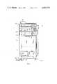
- FIG. 1is a side view of the novel, portable, lavage device
- FIG. 2is a front view of the device shown in FIG. 1;
- FIG. 3is a side view, in partial cross-section, of one of the fluid distributing manifolds and its associated nozzles which direct the cleansing fluid against the item to be cleansed, for instance, arms and hands;
- FIG. 4is a front view of the manifold flange to which the manifold is connected and from which the manifold receives the cleansing fluid;
- FIG. 5is a cross-sectional view of the manifold flange of FIG. 4 taken along lines A--A;
- FIG. 6is a front view of the intake flange which holds the manifold flange in FIG. 4 in place and provides a cleansing fluid to it;
- FIG. 7is a cross-sectional view of the intake flange in FIG. 6 taken along lines A--A;
- FIG. 8is a front view of the housing assembly in which is located two fluid distributing manifolds separated by a wall thus allowing both arms and hands to be simultaneously cleansed;
- FIG. 9is a top view of the housing assembly shown in FIG. 8;
- FIG. 10is a front view of a housing and valves associated therewith which receives pressurized fluid and produces an output fluid to the fluid distributing manifolds which varies in pressure from a maximum pressure to a minimum pressure;
- FIG. 11is a view of one of the impellers as it passes an associated output port showing how the output port is decreased gradually in area to gradually and cyclically vary the pressure from a maximum when the output port is wide open to a minimum as the output port is gradually reduced in area to a minimum;
- FIG. 12is a front view of one of the impellers illustrated in FIG. 10 and FIG. 11;
- FIG. 13is a top view of the impeller of FIG. 12;
- FIG. 14is a side view of the impeller of FIG. 12.
- FIG. 15is a front view of the rubber boot used as a seal with the novel lavage device.
- FIG. 16is a cross-sectional view of the seal shown in FIG. 15.
- FIG. 1is a side view of the novel hydro scrubber 10 which is portable in nature and is therefore mounted on casters or wheels 12.
- the scrubber 10has a mechanical portion 14 in which is located the pumps, valves, motors, and the like, a tank section 16 which contains the cleansing fluid and a manifold section 18 which includes the liquid dispensing manifold.
- An electronic control panel 22sits on top of the unit and is used to turn on the electrical power, to electronically and automatically time the desired cleansing cycle and to select the frequency or number of times per minute the fluid is to be directed against the arms and hands being cleansed.
- Manifold 20includes a plurality of hollow tubes or pipes 30 each of which has a plurality of nozzles 32 (only a representative few of which are shown in FIG. 1 for clarity) directed inwardly toward the hand and arm of the user.
- the plurality of horizontal hollow tubes 30are parallel to each other and are spaced in a circular pattern (as shown in FIG. 2) when viewed from either the front or back of said lavage device 10 and the plurality of spaced nozzles 32 spray liquid toward the hand and arm in the center of said circular pattern.
- Each of said tubes 30has a portion 34 which is curved inwardly toward the center axis of said circular pattern where they attach to a circular manifold 36 which receives the cleansing fluid from a pipe 38 and distributes the fluid to the horizontal manifold tubes 30. Further, at least one spray nozzle 40 is located on the curved end portion 34 of the hollow tubes 30 and at least one spray nozzle 42 is mounted on the center of circular manifold 36 for spraying said liquid toward and perpendicular to the plane of said circular pattern for aiding in the cleansing of the fingernails of the user.
- a foot actuated switch 44is attached to the lavage device 10 by means of electrical cable 46 whereby when each of the arms of the user are inserted into a corresponding rubber boot 28 for cleansing, the use of the foot on foot switch 44 can start the cleansing cycle.
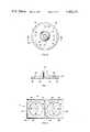
- FIG. 2is a front view of the portable lavage device 10 shown in FIG. 1.
- the unitis mounted on wheels 12 for portability and includes mechanical section 14, the fluid containing section 16, and the manifold section 18 which includes two liquid dispensing manifolds 20.
- the manifold section 18which includes two liquid dispensing manifolds 20.
- foot actuated switch 44is connected by cable 46 to the unit.
- the electronic control unit 22sits on top of the device 10 and has the electrical power on/off switch, the timer meter and corresponding selector switch and the switch for controlling the frequency at which the cleansing fluid is directed against the skin of the user thereof.
- a wall 48separates the left and right liquid dispensing manifolds 20.
- Manifold section 18is preferably made of a clear plastic including top wall 50, end walls 52, back wall 54, and the front wall 26 as shown in FIG. 1.
- the mounting panel 24has been omitted in FIG. 2 within circle 56 in order to more clearly view the end of the parallel, horizontally spaced tubes 30 which form the liquid dispensing manifolds 20.
- a liquid level gauge 58 or any other device for indicating the level of the fluid within the storage tank 16is shown on the front of said lavage device 10.
- FIG. 3is a side view of one of the fluid distributing manifolds 20 and its associated nozzles which direct the cleansing fluid against the items to be cleansed, for instance arms and hands.
- FIG. 3For purposes of clarity of FIG. 3, only two of the plurality of parallel, horizontally spaced tubes 30 are shown. Normally, six of tubes 30 are used as shown in FIG. 2. Again, it will be noted that each of said tubes 30 has a portion 34 of one end curved inwardly towards the center axis of the circular pattern formed by said horizontal hollow tubes 30 when viewed from the end of the tubes (as in FIG. 2) with each curved end 34 being mounted in an orifice on and supported by circular manifold 36.
- the circular manifold 36is attached to the rear wall 54 by means of a manifold flange 58 with bolts or other fasteners which fit through orifices 60. Seal 62 forms a water tight connection with the back wall 54 and prevents any leakage from circular manifold 36 and manifold flange 58.
- the forward end of each of the horizontal hollow tubes 30 which form the manifold 20are mounted in recesses 64 in mounting plate or panel 24.
- the mounting plate 24is rigidly attached to front wall 26 by means of bolts, screws or other fasteners 66.
- a rubber boot 28shown in cross-section in FIG. 3, and which is held in place by a sealing ring 68 which mounts over the shoulders 70 of rubber boot 28 to hold it tightly in place.
- the sealing ring 68may be fastened to the mounting plate 24 with screw 72 or other fastening means.
- the rubber boot 28allows the arm of the user to be inserted there-through into the cleansing chamber into the center of the circular pattern fromed by horizontal hollow tubes 30 each of which has a plurality of spaced nozzles 32 for spraying the cleansing liquid toward the center of said circular pattern.
- the spray nozzles 40 on the curved end 34 of the spaced horizontal tubes 30have a 60 degree spray angle as does nozzle 42 which is directly on the front end of circular manifold 36 while the nozzles 32 on the horizontal portion of spaced hollow tubes 30 have a 30 degree spray angle.
- the 60 degree angle on the spray nozzles 40 and 42insure that the fingernails and fingers of the user of the lavage device are thoroughly encompassed and cleansed.
- the spray nozzles 74are positioned such that the end of the rubber boot 28 which is in contact with the arm of the user is continuously and completely sprayed with the cleansing fluid to insure that no germs can survive in that transition area between that part of the arm not to be cleansed and that part of the arm that is within the cleansing chamber of lavage device.
- rubber boot 28has an indentation 76 formed in the truncated end of the conical shaped boot.
- This indentation 76causes a secure fit about the arm of the user and, when the arm is withdrawn after the cleansing cycle is completed, the flexibility of rubber boot 28 and the snug fit of the indentation 76 about the arm of the user turns rubber boot 28 inside out as the arm is withdrawn thus keeping the sterilized interior side of the rubber boot 28 in contact with the sterilized arm thus preventing any germs or bacteria from making contact therewith as the arm is withdrawn.
- FIG. 4is a front view of the circular flange 36 to which is attached the ends of the spaced, parallel, horizontal hollow tubes 30 forming the fluid distributing manifold 20.
- Orifices 60are for the screws or bolts which attach the circular flange 36 to the rear wall 54 of the housing. These holes or orifices 60 are formed in flange 78 from which extends a cylindrical portion 87 having a slanted face 82 in which orifices 80 are formed and connect to the interior thereof and to the entrance port 88 shown in FIG. 3 and FIG. 5.
- On the flat front face 86is an orifice 84 in which is mounted spray nozzle 42 as shown in FIG. 3.
- FIG. 5is a cross-sectional view of the circular flange 36 shown in FIG. 4 taken along lines A--A.
- the basehas a flange 78 on the back side of which are orifices 60 which may have threads and extend partially into the base as shown in FIG. 5 or which may extend entirely through the base as shown in FIG. 3 but, in any case, which are used for attaching the circular flange 36 to the rear wall 54.
- Recesses 62are used for seals to be placed therein to prevent fluid leakage between the circular flange 36 and the rear wall 54.
- the fluidenters inlet port 88 and exits through ports 80 to the horizontal hollow tubes 30 and through orifice 84 to nozzle 42.
- cylindrical extension 87which extends upwardly from base 78 has a face 82 forming a slanted edge thereof in which orifices 80 are located.
- the faces 82are slanted at an angle sufficient to allow the curved ends 34 of the horizontal hollow tubes 30 to be mounted therein as shown in FIG. 3. Such an angle permits the cleansing fluid to enter the horizontal pipes 30 at a gentle angle instead of a right angle thus reducing the noise which would be generated if the fluid had to enter the orifices 80 and, thus tubes 30, at 90 degree angles.
- FIG. 6is a front view of the intake flange 58 which is shown in FIG. 3, and which cooperates with the circular flange 36 to carry the cleansing fluid from the pump to the distributing manifold 20.
- the flangesimply is a flat plate 90 having orifices 60 therein through which screws or bolts or other fastening means are inserted to attach the intake flange to the circular flange as shown in FIG. 3.
- FIG. 7is a cross-section view of the intake flange 58 taken along lines A--A of FIG. 6.
- Recesses 62are for the purpose of placing seals therein to prevent any fluid leakage between the rear wall 54 and the intake flange 58.
- the fluidenters the flange through orifice 92 and communicates with the circular flange 78 as stated previously.
- FIG. 8is a front view of the housing or manifold assembly 18 for containing the plurality of parallel, horizontally spaced tubes 30 as shown in FIG. 1.
- the housing assemblyincludes top wall 50, bottom wall 94, and side walls 52.
- Center wall 48divides the housing into two chambers but, as shown, divider wall 48 only partially divides the two compartments.
- Bottom wall 94is really the top wall of the fluid holding tank 16 and has therein an orifice 96 for draining the excess fluid back into tank 16 from either chamber formed by center divider wall 48 where the fluid can be recirculated.
- Back wall 54has orifices 60 for bolts or screws or other attaching means to fasten the circular flange 36 and the intake flange 58 to the back wall 54.
- Orifice 98communicates with the input orifice 88 of the circular flange 36 and receives fluid from orifice 92 on the intake flange 58.
- Orifices 66 in front wall 26receives bolts, screws or other attaching means in order to fasten a front mounting plate 24 to the front wall 26 as shown in FIG. 3.
- FIG. 9is a top view of the housing assembly shown in FIG. 8 and, in particular, illustrates the manner in which orifice 96 in bottom wall 94 extends partially into each of the chambers formed by divider wall 48 to drain the excess fluid therefrom. Further, orifice 98 is shown on back wall 54 for passing the cleansing fluid from the intake flange 58 to the circular flange 36. Also in front wall 26 is illustrated orifice 100 for receiving mounting plate 24.
- the preferred material for the top wall, side walls, back and front walls, and the bottom wallis on-half inch clear plexiglas although, of course, other materials such as any metal could be used so long as it resists corrosion.
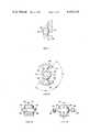
- FIG. 10is a front view of a housing and valves associated therewith which receive pressurized fluid and transmit a fluid to the fluid distributing manifolds which cyclically varies in pressure from a maximum pressure to a minimum pressure.
- One of the problems associated with the prior artis the fact that a pulsating jet of cleansing fluid is utilized. Because the cleansing fluid supply is turned alternately completely on and completely off at a high frequency, the sudden stopping and surging of the liquid creates a tremendous pounding which generates a noise level that is unacceptable. It is therefore necessary to vary the fluid pressure from a maximum to a minimum pressure cyclically without completely interrupting the flow of the cleansing fluid.
- FIG. 10is a front view of a housing and valves associated therewith which receive pressurized fluid and transmit a fluid to the fluid distributing manifolds which cyclically varies in pressure from a maximum pressure to a minimum pressure.
- a two speed motor 102drives a V-belt pulley 104 through shaft 106.
- a V-belt 108couples pulley 104 with a larger pulley 110 which is mounted on shaft 112.
- Shaft 112extends into valve housing 114 which has two output ports 116 and 118 respectively and input port 120.
- the cleansing fluidenters input port 120 under pressure from a source such as a pump (not shown).
- a sourcesuch as a pump (not shown).
- impellers 122 and 124are mounted on shaft 112 inside housing 114. As will be seen with respect to FIG. 12, impellers 122 and 124 are shaped generally in a figure eight configuration and are positioned 90 degrees apart.
- flange 126 of impeller 124is blocking orifice 118 to its maximum thus allowing only a small portion of the orifice 118 free to pass cleansing fluid to the fluid distrubuting manifold 20 to which it is connected.
- impeller 122which is 90 degrees rotationally spaced from impeller 124, has both its upper and lower flanges 128 and 130 clear of orifice 116 thus allowing maximum water pressure to pass to the fluid distributing manifold 20 to which this orifice is connected.
- impeller 124will have its flanges clear of orifice 118 while impeller 122 will have one of its upper or lower flanges 128 or 130 blocking orifice 116 to its maximum.
- the fluid being coupled to the fluid distributing manifold 20 from orifice 116is at its maximum pressure.
- the fluidnot be completely stopped, or pulsed, in order to reduce the noise level and to permit continued usage without irritation to the skin.
- the flanges forming impellers 122 and 124are beveled at an angle on each end thereof.
- flange 128 of impeller 122is beginning to move into orifice 116.
- the flangeis just outside the orifice and maximum pressure is being passed through the orifice 116.
- flange 128has moved such that the tip of the flange is just entering orifice 116 and begins to gradually cut off the fluid flow.
- the tip of flange 128has moved to a point whereby approximately one-fourth of the fluid flow has been reduced through orifice 116.
- the impeller 128has moved sufficiently into orifice 116 to cut off approximately one-half of the fluid flow.
- the flange 128 of impeller 122has moved sufficiently through orifice 116 to close off approximately three-fourths of the fluid flow and at point F, the flange 128 has moved sufficiently through orifice 116 to reduce the fluid flow almost to the minimum pressure.
- the flange 128 of impeller 122has moved entirely into the orifice 116 thereby blocking fluid flow to the maximum such that fluid can pass only on each side 132 and 134 of flange 128.
- the fluid pressurevaries cyclically from a maximum pressure to a minimum pressure with a gradual change taking place between the point of the maximum pressure to the point of minimum pressure and vice-versa. This is extremely important because, as stated previously, a pulsating jet, wherein the fluid pressure is abruptly reduced to zero pressure and then abruptly increased to maximum pressure, creates a pounding and thus an unacceptable noise level.
- the resulting cleansing fluidis changed in pressure 800 times per minute and, if the motor speed is increased to 600 rpm, the pressure of the cleansing fluid is changed 1200 times per minute from a maximum to a minimum. This can be irritating on the skin when the water is pulsed or the pressure is changed from a zero pressure to maximum pressure.
- Impeller 122has an upper flange 128 and a lower flange 130 and is generally in the shape of a figure-eight. Each end 136 of the upper flange 128 and each end 138 of the lower flange 130 is cut at an angle so as to form a point 140 as shown in FIG. 12.
- Orifice 142is for the insertion of the drive shaft 112 which is coupled by the V-belts to motor 102.
- An orifice 144allows a set screw or other type of fastening unit to attach the impeller 122 to shaft 112.
- the width of flange 128is such that it does not completely block the output orifice 116 shown in FIG. 10. It has been found that the preferred ratio of the closed area of the output orifice to the area left open is 82% to 18%.
- FIG. 14is a side view of the impeller 122.
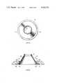
- FIG. 15is a front view of the rubber boot 28 illustrated in FIG. 1 and includes a flange 70, a truncated cone body 146 and an indentation or groove 76 at the end thereof.
- FIG. 16illustrates how the rubber boot looks in cross-section when it is mounted in the mounting flange 24 shown in FIG. 1.
- the boothas a flange 70 which is placed in indentation 148 over which is placed a sealing ring 150 which is held in place by screws 152.
- Flange 70is slightly thicker than indentation 148 but because it is made of rubber such as amtex latex rubber compound no. 15030, amber, it is held tightly in place.
- the rubber boot 28has a truncated cone body 146 which terminates with a groove 76 at the end thereof through which the arm and hand must pass. This configuration is very important for hygenic purposes.
- indentation 76fits snugly about any size arm since it is made of rubber and therefore is elastic in nature.
- nozzles 74direct the cleansing fluid on the inside surfaces of the rubber boot 28 during the cleansing operation.
- the indentation 76holds firmly about the arm causing the rubber boot 28 to pull inside out as the arm is removed.
- the sanitized inside surface of the boot 28comes in contact with the part of the body which has been cleansed.
- the cleansed armis not subjected to any part of the apparatus that has not been cleansed or that might contain germs.
- the indentation 76 illustrated in FIG. 16keeps the arm in contact with the sterilized inner surface of rubber booth 28 while the arm and hand are being removed therefrom to prevent contamination of the cleansed arm and hand. Further, the U-shaped groove 76 allows different size arms to fit snugly in the rubber boot and still prevents blood cut off for the larger arm inasmuch as it is flexible and can give.
- the electrical control unit 22includes a timer built therein which can be set to any predetermined amount of time, for instance, 90 seconds, and which will also automatically shut the unit off when the preset amount of time has elapsed.
- the present inventionrelates to a unique lavage device which saves valuable time with the possibility of saving human lives. It has a great number of advantages over a standard ten minute presurgical scrub including reducing the scrub time by as much as 85%, achieving consistent presurgical scrub results, causing much less irritation to the skin, providing cost and energy efficient use, increasing productivity with time saving, promoting enthusiasm for safety and cleanliness and removing more skin bacteria thus reducing risk of contamination.
Landscapes
- Health & Medical Sciences (AREA)
- Surgery (AREA)
- Life Sciences & Earth Sciences (AREA)
- Heart & Thoracic Surgery (AREA)
- Molecular Biology (AREA)
- Oral & Maxillofacial Surgery (AREA)
- Engineering & Computer Science (AREA)
- Biomedical Technology (AREA)
- Nuclear Medicine, Radiotherapy & Molecular Imaging (AREA)
- Medical Informatics (AREA)
- Pathology (AREA)
- Animal Behavior & Ethology (AREA)
- General Health & Medical Sciences (AREA)
- Public Health (AREA)
- Veterinary Medicine (AREA)
- Infusion, Injection, And Reservoir Apparatuses (AREA)
- Jet Pumps And Other Pumps (AREA)
- Nozzles (AREA)
- Cleaning By Liquid Or Steam (AREA)
Abstract
Description
Claims (21)
Priority Applications (10)
| Application Number | Priority Date | Filing Date | Title |
|---|---|---|---|
| US06/248,510US4402331A (en) | 1981-03-27 | 1981-03-27 | Portable lavage device |
| PH26971APH18165A (en) | 1981-03-27 | 1982-03-10 | Portable lavage device |
| IN297/CAL/82AIN158335B (en) | 1981-03-27 | 1982-03-17 | |
| IL6527482AIL65274A (en) | 1981-03-27 | 1982-03-17 | Portable lavage device for hands and arms |
| AR28883582AAR228391A1 (en) | 1981-03-27 | 1982-03-22 | DISPLACABLE WASHING DEVICE, PARTICULARLY TO PROPERLY WASH A SURGEON'S ARMS AND HANDS |
| IT6739782AIT1200047B (en) | 1981-03-27 | 1982-03-26 | PORTABLE WASHING DEVICE AND WASHING METHOD PARTICULARLY FOR THE BACTERIAL DECONTAMINATION OF THE HANDS AND ARMS OF STAFF EMPLOYED IN SURGERY OPERATIONS |
| CA000399498ACA1206067A (en) | 1981-03-27 | 1982-03-26 | Portable lavage device |
| ES510831AES8401841A1 (en) | 1981-03-27 | 1982-03-26 | Portable lavage device |
| IE721/82AIE52771B1 (en) | 1981-03-27 | 1982-03-26 | Partable lavage device |
| US06/500,163US4465522A (en) | 1981-03-27 | 1983-06-01 | Method for surgically cleaning hands and arms |
Applications Claiming Priority (1)
| Application Number | Priority Date | Filing Date | Title |
|---|---|---|---|
| US06/248,510US4402331A (en) | 1981-03-27 | 1981-03-27 | Portable lavage device |
Related Child Applications (1)
| Application Number | Title | Priority Date | Filing Date |
|---|---|---|---|
| US06/500,163DivisionUS4465522A (en) | 1981-03-27 | 1983-06-01 | Method for surgically cleaning hands and arms |
Publications (1)
| Publication Number | Publication Date |
|---|---|
| US4402331Atrue US4402331A (en) | 1983-09-06 |
Family
ID=22939466
Family Applications (1)
| Application Number | Title | Priority Date | Filing Date |
|---|---|---|---|
| US06/248,510Expired - LifetimeUS4402331A (en) | 1981-03-27 | 1981-03-27 | Portable lavage device |
Country Status (8)
| Country | Link |
|---|---|
| US (1) | US4402331A (en) |
| AR (1) | AR228391A1 (en) |
| CA (1) | CA1206067A (en) |
| ES (1) | ES8401841A1 (en) |
| IE (1) | IE52771B1 (en) |
| IL (1) | IL65274A (en) |
| IT (1) | IT1200047B (en) |
| PH (1) | PH18165A (en) |
Cited By (39)
| Publication number | Priority date | Publication date | Assignee | Title |
|---|---|---|---|---|
| US4802508A (en)* | 1988-03-31 | 1989-02-07 | Pacific Biosystems, Inc. | Cyclically varying pulsating fluid supply system |
| US4817651A (en)* | 1987-10-26 | 1989-04-04 | Scientific Growth, Inc. | Hand and forearm cleansing apparatus |
| US4945901A (en)* | 1989-03-22 | 1990-08-07 | Burcke Jr Harry J | Hand therapy apparatus and method therefor |
| US5070864A (en)* | 1990-07-30 | 1991-12-10 | Lemons David H | Body massage apparatus |
| US5318056A (en)* | 1986-03-20 | 1994-06-07 | Safety-Kleen Corporation | Solvent recirculating type spray gun cleaner |
| US5477984A (en)* | 1993-04-27 | 1995-12-26 | Saraya Co., Ltd. | Liquid jetting apparatus for jetting liquid toward a hand for disinfection thereof |
| WO1996026795A1 (en)* | 1995-02-27 | 1996-09-06 | Meritech, Inc. | Automated cleansing chamber with air knife |
| US5634890A (en)* | 1995-05-09 | 1997-06-03 | Aquasage, Inc. | Water massage therapy device and method for using the same |
| US5727579A (en)* | 1996-05-29 | 1998-03-17 | 144 Limited Partnership | Automatic hand washing and drying apparatus including combined blow drying means and towel dispensing means |
| US5823447A (en)* | 1996-08-27 | 1998-10-20 | Meritech, Inc. | Angled fan nozzle and unibody cylinder |
| WO1998053752A3 (en)* | 1997-05-30 | 1999-03-04 | 700303 Alberta Ltd | Apparatus for and method of cleaning hands |
| US5964955A (en)* | 1997-11-14 | 1999-10-12 | Steris Corporation | System for coupling operating equipment to a washer |
| US5992430A (en)* | 1998-09-28 | 1999-11-30 | 144 Limited Partnership | Automatic hand washing and drying apparatus including combined blow drying means, towel dispensing means and waste disposal means |
| US6003529A (en)* | 1997-09-30 | 1999-12-21 | Adamation, Inc. | Dish machine/pot washer |
| WO2000018284A1 (en) | 1998-09-28 | 2000-04-06 | 144 Limited Partnership | Hand washing and drying apparatus and system including waste disposal apparatus and method |
| US6110292A (en)* | 1997-08-12 | 2000-08-29 | Warren R. Jewett | Oscillating liquid jet washing system |
| US6161227A (en)* | 1999-08-17 | 2000-12-19 | Bargenquast; Scott | Portable hand cleaning device |
| US6341612B1 (en) | 2000-03-09 | 2002-01-29 | Steris Inc | Two compartment container for neutralizing used cleaning solutions |
| FR2816190A1 (en)* | 2000-11-06 | 2002-05-10 | Innov Concept Solutions | Hand washer for garage mechanics has housing with foam feed and collector for solid and liquid waste |
| US6431189B1 (en)* | 1997-06-02 | 2002-08-13 | 700303 Alberta Ltd. | Apparatus for and method of disinfecting hands |
| US6527760B1 (en) | 2000-09-25 | 2003-03-04 | Vijay B. Vad | Out-patient joint lavage kit and protocol |
| US6550487B1 (en) | 2000-03-09 | 2003-04-22 | Steris Inc. | Apparatus for removing deposits from enclosed chambers |
| US6770150B1 (en) | 2000-03-09 | 2004-08-03 | Steris Inc. | Process for removing deposits from enclosed chambers |
| US7607443B2 (en)* | 2006-10-31 | 2009-10-27 | Resurgent Health & Medical, Llc | Wash chamber for automated appendage-washing apparatus |
| US7659824B2 (en) | 2006-10-31 | 2010-02-09 | Resurgent Health & Medical, Llc | Sanitizer dispensers with compliance verification |
| US7698770B2 (en) | 2006-10-31 | 2010-04-20 | Resurgent Health & Medical, Llc | Automated appendage cleaning apparatus with brush |
| US7818083B2 (en) | 2006-10-31 | 2010-10-19 | Resurgent Health & Medical, Llc | Automated washing system with compliance verification and automated compliance monitoring reporting |
| US8146613B2 (en) | 2008-04-29 | 2012-04-03 | Resurgent Health & Medical, Llc | Wash chamber for surgical environment |
| DE102011052555A1 (en)* | 2011-08-10 | 2013-02-14 | Hokwang Industries Co., Ltd. | Multidirectional air discharge hand drying apparatus used in public lavatory facilities, has casing which includes two air discharge nozzles ejecting high-pressure airflows with output airflow axes crossed in hand drying compartment |
| US20140090731A1 (en)* | 2012-09-28 | 2014-04-03 | Grundfos Holding A/S | Dosing manifold and system |
| US8950019B2 (en) | 2007-09-20 | 2015-02-10 | Bradley Fixtures Corporation | Lavatory system |
| US8997271B2 (en) | 2009-10-07 | 2015-04-07 | Bradley Corporation | Lavatory system with hand dryer |
| US9170148B2 (en) | 2011-04-18 | 2015-10-27 | Bradley Fixtures Corporation | Soap dispenser having fluid level sensor |
| US9267736B2 (en) | 2011-04-18 | 2016-02-23 | Bradley Fixtures Corporation | Hand dryer with point of ingress dependent air delay and filter sensor |
| US9758953B2 (en) | 2012-03-21 | 2017-09-12 | Bradley Fixtures Corporation | Basin and hand drying system |
| US10041236B2 (en) | 2016-06-08 | 2018-08-07 | Bradley Corporation | Multi-function fixture for a lavatory system |
| US10100501B2 (en) | 2012-08-24 | 2018-10-16 | Bradley Fixtures Corporation | Multi-purpose hand washing station |
| US11015329B2 (en) | 2016-06-08 | 2021-05-25 | Bradley Corporation | Lavatory drain system |
| US20220175197A1 (en)* | 2020-12-04 | 2022-06-09 | Thuan Dac Ngo | Hand washing, disinfection and automatic massage machine, and method of operating the same |
Families Citing this family (1)
| Publication number | Priority date | Publication date | Assignee | Title |
|---|---|---|---|---|
| US11666185B1 (en) | 2020-10-27 | 2023-06-06 | Travis Windsor | Portable hand-washing kit |
Citations (5)
| Publication number | Priority date | Publication date | Assignee | Title |
|---|---|---|---|---|
| US3227158A (en)* | 1961-05-08 | 1966-01-04 | Aquatec Corp | Method and apparatus for oral hygiene |
| US3416544A (en)* | 1966-12-09 | 1968-12-17 | Paiva Joseph | Tool washing machine |
| US3699984A (en)* | 1971-01-12 | 1972-10-24 | Charles T Davis | Cleaning and sterilizing device |
| US3757806A (en)* | 1972-01-19 | 1973-09-11 | Us Army | Pulsating hydrojet lavage device |
| US3918987A (en)* | 1973-11-09 | 1975-11-11 | Rudolph J Kopfer | Surgeon hand and arm scrubbing apparatus |
- 1981
- 1981-03-27USUS06/248,510patent/US4402331A/ennot_activeExpired - Lifetime
- 1982
- 1982-03-10PHPH26971Apatent/PH18165A/enunknown
- 1982-03-17ILIL6527482Apatent/IL65274A/enunknown
- 1982-03-22ARAR28883582Apatent/AR228391A1/enactive
- 1982-03-26CACA000399498Apatent/CA1206067A/ennot_activeExpired
- 1982-03-26ESES510831Apatent/ES8401841A1/ennot_activeExpired
- 1982-03-26ITIT6739782Apatent/IT1200047B/enactive
- 1982-03-26IEIE721/82Apatent/IE52771B1/enunknown
Patent Citations (5)
| Publication number | Priority date | Publication date | Assignee | Title |
|---|---|---|---|---|
| US3227158A (en)* | 1961-05-08 | 1966-01-04 | Aquatec Corp | Method and apparatus for oral hygiene |
| US3416544A (en)* | 1966-12-09 | 1968-12-17 | Paiva Joseph | Tool washing machine |
| US3699984A (en)* | 1971-01-12 | 1972-10-24 | Charles T Davis | Cleaning and sterilizing device |
| US3757806A (en)* | 1972-01-19 | 1973-09-11 | Us Army | Pulsating hydrojet lavage device |
| US3918987A (en)* | 1973-11-09 | 1975-11-11 | Rudolph J Kopfer | Surgeon hand and arm scrubbing apparatus |
Cited By (62)
| Publication number | Priority date | Publication date | Assignee | Title |
|---|---|---|---|---|
| US5318056A (en)* | 1986-03-20 | 1994-06-07 | Safety-Kleen Corporation | Solvent recirculating type spray gun cleaner |
| US4817651A (en)* | 1987-10-26 | 1989-04-04 | Scientific Growth, Inc. | Hand and forearm cleansing apparatus |
| US4802508A (en)* | 1988-03-31 | 1989-02-07 | Pacific Biosystems, Inc. | Cyclically varying pulsating fluid supply system |
| US4945901A (en)* | 1989-03-22 | 1990-08-07 | Burcke Jr Harry J | Hand therapy apparatus and method therefor |
| US5070864A (en)* | 1990-07-30 | 1991-12-10 | Lemons David H | Body massage apparatus |
| US5477984A (en)* | 1993-04-27 | 1995-12-26 | Saraya Co., Ltd. | Liquid jetting apparatus for jetting liquid toward a hand for disinfection thereof |
| WO1996026795A1 (en)* | 1995-02-27 | 1996-09-06 | Meritech, Inc. | Automated cleansing chamber with air knife |
| US5634890A (en)* | 1995-05-09 | 1997-06-03 | Aquasage, Inc. | Water massage therapy device and method for using the same |
| US5727579A (en)* | 1996-05-29 | 1998-03-17 | 144 Limited Partnership | Automatic hand washing and drying apparatus including combined blow drying means and towel dispensing means |
| US5823447A (en)* | 1996-08-27 | 1998-10-20 | Meritech, Inc. | Angled fan nozzle and unibody cylinder |
| WO1998053752A3 (en)* | 1997-05-30 | 1999-03-04 | 700303 Alberta Ltd | Apparatus for and method of cleaning hands |
| US6431189B1 (en)* | 1997-06-02 | 2002-08-13 | 700303 Alberta Ltd. | Apparatus for and method of disinfecting hands |
| US6176941B1 (en)* | 1997-08-12 | 2001-01-23 | Warren R. Jewett | Method of removing contaminants from an epidermal surface using an oscillating fluidic spray |
| US6110292A (en)* | 1997-08-12 | 2000-08-29 | Warren R. Jewett | Oscillating liquid jet washing system |
| US6003529A (en)* | 1997-09-30 | 1999-12-21 | Adamation, Inc. | Dish machine/pot washer |
| US5964955A (en)* | 1997-11-14 | 1999-10-12 | Steris Corporation | System for coupling operating equipment to a washer |
| WO2000018284A1 (en) | 1998-09-28 | 2000-04-06 | 144 Limited Partnership | Hand washing and drying apparatus and system including waste disposal apparatus and method |
| US6131587A (en)* | 1998-09-28 | 2000-10-17 | 144 Limited Partnership | Hand washing and drying apparatus and system including waste disposal apparatus and method |
| US5992430A (en)* | 1998-09-28 | 1999-11-30 | 144 Limited Partnership | Automatic hand washing and drying apparatus including combined blow drying means, towel dispensing means and waste disposal means |
| US6161227A (en)* | 1999-08-17 | 2000-12-19 | Bargenquast; Scott | Portable hand cleaning device |
| US6341612B1 (en) | 2000-03-09 | 2002-01-29 | Steris Inc | Two compartment container for neutralizing used cleaning solutions |
| US6550487B1 (en) | 2000-03-09 | 2003-04-22 | Steris Inc. | Apparatus for removing deposits from enclosed chambers |
| US6562145B2 (en) | 2000-03-09 | 2003-05-13 | Steris Inc. | Method of cleaning a surface with a system having a two compartment container for neutralizing used cleaning solutions |
| US6770150B1 (en) | 2000-03-09 | 2004-08-03 | Steris Inc. | Process for removing deposits from enclosed chambers |
| US6527760B1 (en) | 2000-09-25 | 2003-03-04 | Vijay B. Vad | Out-patient joint lavage kit and protocol |
| FR2816190A1 (en)* | 2000-11-06 | 2002-05-10 | Innov Concept Solutions | Hand washer for garage mechanics has housing with foam feed and collector for solid and liquid waste |
| US7659824B2 (en) | 2006-10-31 | 2010-02-09 | Resurgent Health & Medical, Llc | Sanitizer dispensers with compliance verification |
| US8110047B2 (en) | 2006-10-31 | 2012-02-07 | Resurgent Health & Medical, Llc | Automated washing system with compliance verification |
| US7617830B2 (en) | 2006-10-31 | 2009-11-17 | Resurgent Health & Medical, Llc | Wash chamber for automated appendage-washing apparatus |
| US7641740B2 (en) | 2006-10-31 | 2010-01-05 | Resurgent Health & Medical, Llc | Wash chamber for automated appendage-washing apparatus |
| US7607443B2 (en)* | 2006-10-31 | 2009-10-27 | Resurgent Health & Medical, Llc | Wash chamber for automated appendage-washing apparatus |
| US7682464B2 (en) | 2006-10-31 | 2010-03-23 | Resurgent Health & Medical, Llc | Automated washing system with compliance verification |
| US7698770B2 (en) | 2006-10-31 | 2010-04-20 | Resurgent Health & Medical, Llc | Automated appendage cleaning apparatus with brush |
| US7754022B2 (en) | 2006-10-31 | 2010-07-13 | Resurgent Health & Medical, Llc | Wash chamber for appendage-washing method |
| US7754021B2 (en) | 2006-10-31 | 2010-07-13 | Resurgent Health & Medical, Llc | Wash chamber for appendage-washing apparatus |
| US7757700B2 (en) | 2006-10-31 | 2010-07-20 | Resurgent Health & Medical, Llc | Wash chamber for automated appendage-washing apparatus |
| US7758701B2 (en) | 2006-10-31 | 2010-07-20 | Resurgent Health & Medical, Llc | Wash chamber for automated appendage-washing apparatus |
| US7789095B2 (en) | 2006-10-31 | 2010-09-07 | Resurgent Health & Medical, Llc | Wash chamber for automated appendage-washing apparatus |
| US7818083B2 (en) | 2006-10-31 | 2010-10-19 | Resurgent Health & Medical, Llc | Automated washing system with compliance verification and automated compliance monitoring reporting |
| US7883585B2 (en) | 2006-10-31 | 2011-02-08 | Resurgent Health & Medical, Llc | Wash chamber for appendage-washing method |
| US7901513B2 (en) | 2006-10-31 | 2011-03-08 | Resurgent Health & Medical, LLC. | Wash chamber for appendage-washing method |
| US7993471B2 (en) | 2006-10-31 | 2011-08-09 | Barnhill Paul R | Wash chamber for automated appendage-washing apparatus |
| US8085155B2 (en) | 2006-10-31 | 2011-12-27 | Resurgent Health & Medical, Llc | Sanitizer dispensers with compliance verification |
| US7607442B2 (en) | 2006-10-31 | 2009-10-27 | Resurgent Health & Medical, Llc | Wash chamber for automated appendage-washing apparatus |
| US8950019B2 (en) | 2007-09-20 | 2015-02-10 | Bradley Fixtures Corporation | Lavatory system |
| US8294585B2 (en) | 2008-04-29 | 2012-10-23 | Resurgent Health & Medical, Llc | Complete hand care |
| US8377229B2 (en) | 2008-04-29 | 2013-02-19 | Resurgent Health & Medical, Llc | Ingress/egress system for hygiene compliance |
| US8400309B2 (en) | 2008-04-29 | 2013-03-19 | Resurgent Health & Medical, Llc | Hygiene compliance |
| US8146613B2 (en) | 2008-04-29 | 2012-04-03 | Resurgent Health & Medical, Llc | Wash chamber for surgical environment |
| US8997271B2 (en) | 2009-10-07 | 2015-04-07 | Bradley Corporation | Lavatory system with hand dryer |
| US9267736B2 (en) | 2011-04-18 | 2016-02-23 | Bradley Fixtures Corporation | Hand dryer with point of ingress dependent air delay and filter sensor |
| US9441885B2 (en) | 2011-04-18 | 2016-09-13 | Bradley Fixtures Corporation | Lavatory with dual plenum hand dryer |
| US9170148B2 (en) | 2011-04-18 | 2015-10-27 | Bradley Fixtures Corporation | Soap dispenser having fluid level sensor |
| DE102011052555A1 (en)* | 2011-08-10 | 2013-02-14 | Hokwang Industries Co., Ltd. | Multidirectional air discharge hand drying apparatus used in public lavatory facilities, has casing which includes two air discharge nozzles ejecting high-pressure airflows with output airflow axes crossed in hand drying compartment |
| US9758953B2 (en) | 2012-03-21 | 2017-09-12 | Bradley Fixtures Corporation | Basin and hand drying system |
| US10100501B2 (en) | 2012-08-24 | 2018-10-16 | Bradley Fixtures Corporation | Multi-purpose hand washing station |
| US9157435B2 (en)* | 2012-09-28 | 2015-10-13 | Grundfos Pumps Manufacturing Corporation | Dosing manifold and system |
| US20140090731A1 (en)* | 2012-09-28 | 2014-04-03 | Grundfos Holding A/S | Dosing manifold and system |
| US10041236B2 (en) | 2016-06-08 | 2018-08-07 | Bradley Corporation | Multi-function fixture for a lavatory system |
| US11015329B2 (en) | 2016-06-08 | 2021-05-25 | Bradley Corporation | Lavatory drain system |
| US20220175197A1 (en)* | 2020-12-04 | 2022-06-09 | Thuan Dac Ngo | Hand washing, disinfection and automatic massage machine, and method of operating the same |
| US12295530B2 (en)* | 2020-12-04 | 2025-05-13 | Thuan Dac Ngo | Hand washing, disinfection and automatic massage machine, and method of operating the same |
Also Published As
| Publication number | Publication date |
|---|---|
| PH18165A (en) | 1985-04-09 |
| IL65274A (en) | 1985-12-31 |
| IT8267397A0 (en) | 1982-03-26 |
| IE820721L (en) | 1982-09-27 |
| IE52771B1 (en) | 1988-02-17 |
| AR228391A1 (en) | 1983-02-28 |
| IL65274A0 (en) | 1982-05-31 |
| ES510831A0 (en) | 1984-01-01 |
| IT1200047B (en) | 1989-01-05 |
| ES8401841A1 (en) | 1984-01-01 |
| CA1206067A (en) | 1986-06-17 |
Similar Documents
| Publication | Publication Date | Title |
|---|---|---|
| US4402331A (en) | Portable lavage device | |
| US4465522A (en) | Method for surgically cleaning hands and arms | |
| JP3444856B2 (en) | Resonant liquid jet cleaning device | |
| US3509874A (en) | Dental cleansing and massaging apparatus | |
| KR100911039B1 (en) | An Air Injection Type Portable Dental Flosses | |
| EP2086696B1 (en) | Wash chamber for automated appendage-washing apparatus | |
| US3757806A (en) | Pulsating hydrojet lavage device | |
| US8511927B2 (en) | Fluid-powered rotating bath accessory | |
| US4802508A (en) | Cyclically varying pulsating fluid supply system | |
| JPH05505331A (en) | Cavity cleaning device | |
| AU550202B2 (en) | Portable lavage device | |
| JPH09262512A (en) | Gas-liquid injector and operating method thereof | |
| WO1983000645A1 (en) | Surgical scrubbing device | |
| JPH11151198A (en) | Endoscope cleaning system | |
| JP2010051528A (en) | Member for spraying and sucking liquid, and device for spraying and sucking liquid | |
| KR200239406Y1 (en) | Oral cavity washer for home | |
| KR200390461Y1 (en) | multi-functional skin washer | |
| KR200412689Y1 (en) | Pneumatic spray skin cleaner for pore washing | |
| CN2291129Y (en) | Fluid jet teeth-cleaning device | |
| JPH04166152A (en) | Sucking beauty apparatus | |
| JPH0723898A (en) | Endoscope arranged with back flow preventive valve | |
| AU8954782A (en) | Surgical scrubbing device | |
| HK1132220B (en) | Wash chamber for automated appendage-washing apparatus | |
| HK1132220A (en) | Wash chamber for automated appendage-washing apparatus |
Legal Events
| Date | Code | Title | Description |
|---|---|---|---|
| AS | Assignment | Owner name:DELTA MANUFACTURING AND SALES, INC., 2708 EAST RAN Free format text:ASSIGNMENT OF ASSIGNORS INTEREST.;ASSIGNORS:TALDO TERRY J.;JACKSON KENNETH R.;REEL/FRAME:003875/0144 Effective date:19810324 | |
| STCF | Information on status: patent grant | Free format text:PATENTED CASE | |
| MAFP | Maintenance fee payment | Free format text:PAYMENT OF MAINTENANCE FEE, 4TH YEAR, PL 96-517 (ORIGINAL EVENT CODE: M170); ENTITY STATUS OF PATENT OWNER: SMALL ENTITY Year of fee payment:4 | |
| AS | Assignment | Owner name:KELLUM, JAMES E., 2114 SUNNYVALE, GRAND PRAIRIE, T Free format text:ASSIGNMENT OF ASSIGNORS INTEREST.;ASSIGNOR:DELTA MANUFACTURING AND SALES, INC.;REEL/FRAME:004711/0708 Effective date:19870414 | |
| FEPP | Fee payment procedure | Free format text:PAYMENT IS IN EXCESS OF AMOUNT REQUIRED. REFUND SCHEDULED (ORIGINAL EVENT CODE: F169); ENTITY STATUS OF PATENT OWNER: SMALL ENTITY | |
| MAFP | Maintenance fee payment | Free format text:PAYMENT OF MAINTENANCE FEE, 8TH YEAR, PL 96-517 (ORIGINAL EVENT CODE: M171); ENTITY STATUS OF PATENT OWNER: SMALL ENTITY Year of fee payment:8 | |
| FEPP | Fee payment procedure | Free format text:MAINTENANCE FEE REMINDER MAILED (ORIGINAL EVENT CODE: REM.); ENTITY STATUS OF PATENT OWNER: SMALL ENTITY | |
| FEPP | Fee payment procedure | Free format text:SURCHARGE FOR LATE PAYMENT, SMALL ENTITY (ORIGINAL EVENT CODE: M286); ENTITY STATUS OF PATENT OWNER: SMALL ENTITY | |
| MAFP | Maintenance fee payment | Free format text:PAYMENT OF MAINTENANCE FEE, 12TH YR, SMALL ENTITY (ORIGINAL EVENT CODE: M285); ENTITY STATUS OF PATENT OWNER: SMALL ENTITY Year of fee payment:12 |