US4401883A - Electric resistance heater - Google Patents
Electric resistance heaterDownload PDFInfo
- Publication number
- US4401883A US4401883AUS06/292,444US29244481AUS4401883AUS 4401883 AUS4401883 AUS 4401883AUS 29244481 AUS29244481 AUS 29244481AUS 4401883 AUS4401883 AUS 4401883A
- Authority
- US
- United States
- Prior art keywords
- tube
- coil
- conductor
- tubes
- terminals
- Prior art date
- Legal status (The legal status is an assumption and is not a legal conclusion. Google has not performed a legal analysis and makes no representation as to the accuracy of the status listed.)
- Expired - Lifetime
Links
- 239000004020conductorSubstances0.000claimsabstractdescription31
- 241001481760Erethizon dorsatumSpecies0.000claimsabstractdescription13
- 238000010438heat treatmentMethods0.000claimsabstractdescription8
- 238000007665saggingMethods0.000claimsabstractdescription4
- 238000005336crackingMethods0.000claimsdescription8
- 229910010293ceramic materialInorganic materials0.000claimsdescription7
- 239000000463materialSubstances0.000claimsdescription5
- 239000002184metalSubstances0.000claims1
- 239000000615nonconductorSubstances0.000claims1
- 239000011819refractory materialSubstances0.000claims1
- 239000000919ceramicSubstances0.000abstractdescription11
- 125000006850spacer groupChemical group0.000description4
- VYPSYNLAJGMNEJ-UHFFFAOYSA-NSilicium dioxideChemical compoundO=[Si]=OVYPSYNLAJGMNEJ-UHFFFAOYSA-N0.000description2
- 239000002657fibrous materialSubstances0.000description2
- 238000009434installationMethods0.000description2
- 229910002060Fe-Cr-Al alloyInorganic materials0.000description1
- AZDRQVAHHNSJOQ-UHFFFAOYSA-NalumaneChemical group[AlH3]AZDRQVAHHNSJOQ-UHFFFAOYSA-N0.000description1
- XAGFODPZIPBFFR-UHFFFAOYSA-NaluminiumChemical compound[Al]XAGFODPZIPBFFR-UHFFFAOYSA-N0.000description1
- 229910052782aluminiumInorganic materials0.000description1
- PNEYBMLMFCGWSK-UHFFFAOYSA-Naluminium oxideInorganic materials[O-2].[O-2].[O-2].[Al+3].[Al+3]PNEYBMLMFCGWSK-UHFFFAOYSA-N0.000description1
- 244000145845chatteringSpecies0.000description1
- 230000006835compressionEffects0.000description1
- 238000007906compressionMethods0.000description1
- 238000010292electrical insulationMethods0.000description1
- 229910000953kanthalInorganic materials0.000description1
- 239000000377silicon dioxideSubstances0.000description1
- 230000035882stressEffects0.000description1
- 230000008646thermal stressEffects0.000description1
Images
Classifications
- H—ELECTRICITY
- H05—ELECTRIC TECHNIQUES NOT OTHERWISE PROVIDED FOR
- H05B—ELECTRIC HEATING; ELECTRIC LIGHT SOURCES NOT OTHERWISE PROVIDED FOR; CIRCUIT ARRANGEMENTS FOR ELECTRIC LIGHT SOURCES, IN GENERAL
- H05B3/00—Ohmic-resistance heating
- H05B3/40—Heating elements having the shape of rods or tubes
- H05B3/42—Heating elements having the shape of rods or tubes non-flexible
- H05B3/46—Heating elements having the shape of rods or tubes non-flexible heating conductor mounted on insulating base
- H—ELECTRICITY
- H05—ELECTRIC TECHNIQUES NOT OTHERWISE PROVIDED FOR
- H05B—ELECTRIC HEATING; ELECTRIC LIGHT SOURCES NOT OTHERWISE PROVIDED FOR; CIRCUIT ARRANGEMENTS FOR ELECTRIC LIGHT SOURCES, IN GENERAL
- H05B3/00—Ohmic-resistance heating
- H05B3/62—Heating elements specially adapted for furnaces
- H05B3/64—Heating elements specially adapted for furnaces using ribbon, rod, or wire heater
Definitions
- Such a furnacehas at least one baffeled plenum through which at least one blower forces air at velocities of up to 100 mph, and the plenum contains at least one electric resistance heater.
- such a heatertypically may have a length in the area of three feet and must support a resistance coil element consuming power in the area of 15,000 to 30,000 watts.
- the coilshould expose as much of its surface to the air as is consistant with structural stability when stressed by the force of the air blast.
- porcupine coil configurationhas never been used for a metallurgical convection heat-treating furnace where the necessary size of the coil, both as to wire gauge and length, presents problems concerning the mounting of the coil.
- the use of a porcupine coilhas been suggested by the prior art for use in comparatively low-voltage hot-blast guns as evidenced by the Pricenski et al U.S. Pat. Nos. 3,551,643 and the Haglund patent 4,207,457.
- the main object of the present inventionis to provide an electric resistance heater capable of enjoying the advantages of the porcupine coil configuration and adapted for commercial use in such a metallurgical convection heat-treatment furnace, for example, where the heater must use heavy gauge resistance wire with a coil length in the the area of three feet or more and mounted so as to be stable and long-lived under the high blast velocities incidental to such service. In such an installation the heater must operate horizontally and transversely with respect to the air blast.
- the electric resistance heater of the present inventioncomprises the necessary elongated coil of resistance wire, particularly when in the form of a porcupine coil.
- a first rigid non-conductive refractory tubeextends through the coil's open coil center so as to support the coil from sagging when horizontally positioned.
- Terminalsare positioned at only one end of the tube, for the opposite ends of the coil, so that the heater can extend horizontally through the air blast plenum with that one end adapted to be fixed to the furnace wall with the terminals projecting through the wall for external power line connection.
- Other installationsalso require that both terminals be at only one end of the heater.
- An electric conductorextends through this tube and one of the coil's ends is connected directly dwith one of the terminals, the other end of the coil being connected, at the other or inner end of the tube, with the conductor, the latter extending backwardly through the tube and connecting with the other of the terminals.
- Any suitable refractory tubeis necessarily made of ceramic material and must support the porcupine coil when used, via the straight legs of the convolution loops, resulting in what are in effect point contacts between the coil and the tube. This subjects the tube to high thermal and mechanical stressing localized at the point contacts, and being necessarily ceramic tube, is subject to cracking which at the voltages required can cause a short-circuit between the coil and the conductor on the inside of the tube. This possibility and its suggestion of short service life under commercial operating conditions, has eliminated the porcupine coil from consideration concerning heavy duty applications.
- the heater of the present inventionuses a second rigid non-conductive refractory tube encircling the conductor inside of the first tube and again for practical reasons this second tube must be made of ceramic material and also capable of cracking when stressed.
- this second tubemust be made of ceramic material and also capable of cracking when stressed.
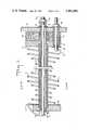
- FIG. 1being a longitudinal section
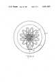
- FIG. 2a cross-section taken on the line II--II in FIG. 1.
- the porcupine coil 1is shown with its helical series of substantially flat convolutions having the characteristic straight legs 1a defining an open coil center formed by the straight legs.
- the coilmust be long and made of heavy gauge resistance wire as compared to prior art porcupine coil proposals.
- the illustrated coiluses NO. 4 gauge wire having a 0.204 inch diameter, the coil is 35 inches long and the convolutions are bunched as closely together as is possible without the convolutions short-circuiting with each other.
- the coilis heat-treated so that the convolutions spacing is permanently set and does not require to be held under tension.
- the coilis designed for operation at 240 volts with a power consumption rating of 30,000 watts.
- the coilis supported against sagging when in operation horizontally positioned, by the first rigid non-conductive refractory tube shown at 2 which is somewhat longer than the coil.
- This tubecan be one of the commercially available refractory tubes made of fused alumina, possibly mixed with silica. There are different types of such commercially available tubes and the one chosen for this tube 2 is preferrably one of those recommended for its strength and maximum resistance to cracking at high temperatures, rather than for its electrical insulating properties at high temperatures.
- the left hand 6a end of the conductor 6extends beyond the flange 7 and one end 1a of the coil is welded to this end of the conductor.
- the right hand end 6b of the conductor 6is threaded for the nut 10, and the end cap 3 and flange 4, at a radially spaced position, carries the second terminal 11 which is in the form of a short conductor arranged somewhat as described before, having a spacer 12 between the end cap 6 and flange 4, a welded-on flange 13 on its inner end and a nut 14 on its threaded outer end. Tightening of the nut 14 positions the terminal with its outer end exposed for connection to the power line.
- the other or right hand end 1b of the coilis welded to this terminal conductor 11 and the terminal may be surrounded by a short ceramic insulating tube 15.
- the previously mentioned second rigid non-conductive refractory tube 16encirlces the conductor 6 inside of the first tube 2.
- the ends of this second tubeis positioned in holes in the two end caps 3 and 3a and the flange 4.
- the second tubefor practical reasons must also be made of a ceramic material.
- the ceramic tubescommercially available there are some recommended more for their electrical insulation properties at elevated temperatures than they are for strength and this type is preferred for the tube 16. It is also subject to cracking under thermal stress and particularly when hot spots are present.
- the first tube 2is preferably made of the ceramic material used for high strength.
- both the tube 2 and 16will crack at the same place so as to risk a short-circuit between the coil 1 and the conductor 6.
- Cracked or opening in radial registration between the two tubesis so improbable that both tubes can crack in a number of places without a short-circuit resulting.
- Such crackingdoes not necessarily result in actual breakage of either tube so as to affect the beam strength of the assembly.
- Such breakageis made improbable in any event unless by chance both tubes weaken at the same place.
- the inside diameter of the tube 2is made larger than the outside diameter of the tube 16 and the latter is chosen with an inside diameter that is larger than the diameter of the conductor 6.
- the circumferential space between the tubes 2 and 16is preferably filled with a soft fibrous ceramic refractory 17 which prevents chattering between the tubes 2 and 16 in the event of vibration induced by the air blast.
- a soft fibrous ceramic refractory 17which prevents chattering between the tubes 2 and 16 in the event of vibration induced by the air blast.
- Such materialalso is used between the spacer 5 and the electrically insulating tube 16 of greater insulating properties, the latter extending from the washer 8 and the outside of the flange 4, via suitable openings in the parts 3 and 4, backwardly so that its inner end is axially in the hole 18 of the counterbore which receives that end of the tube 2.
- soft fibrous ceramic material 18ais packed.
- Such ceramic fibrous materialis also indicated at 19 between the ceramic end cap 3 and mounting flange 4 and in the form of a wall. This material can be any adequately refractory fibrous material providing at least some elastic deformability.
- the electric resistance wire, the conductor 6 and the terminal 11are preferably all made of electric resistance heating wire such as the Fe-Cr-Al alloys sold under the trademark "Kanthal.” Other appropriate electric resistance material can be used.
- a porcupine coilis usually described as comprising a substantially helical series of substantially flat convolutions having straight legs and hooked ends.
Landscapes
- Resistance Heating (AREA)
- Furnace Details (AREA)
Abstract
Description
Claims (4)
Priority Applications (1)
| Application Number | Priority Date | Filing Date | Title |
|---|---|---|---|
| US06/292,444US4401883A (en) | 1981-08-14 | 1981-08-14 | Electric resistance heater |
Applications Claiming Priority (1)
| Application Number | Priority Date | Filing Date | Title |
|---|---|---|---|
| US06/292,444US4401883A (en) | 1981-08-14 | 1981-08-14 | Electric resistance heater |
Publications (1)
| Publication Number | Publication Date |
|---|---|
| US4401883Atrue US4401883A (en) | 1983-08-30 |
Family
ID=23124698
Family Applications (1)
| Application Number | Title | Priority Date | Filing Date |
|---|---|---|---|
| US06/292,444Expired - LifetimeUS4401883A (en) | 1981-08-14 | 1981-08-14 | Electric resistance heater |
Country Status (1)
| Country | Link |
|---|---|
| US (1) | US4401883A (en) |
Cited By (6)
| Publication number | Priority date | Publication date | Assignee | Title |
|---|---|---|---|---|
| US4549072A (en)* | 1983-01-03 | 1985-10-22 | Lincoln Manufacturing Company, Inc. | Proofing or heating cabinet |
| US4695821A (en)* | 1985-01-03 | 1987-09-22 | O/Y Kyro A/B Tamglass | Resistor element assembly for a heating furnace of glass sheets and method of replacing a resistor element |
| US4712086A (en)* | 1985-01-03 | 1987-12-08 | O/Y Kyro A/B Tamglass | Support frame for resistor elements in a heating furnace for glass sheets |
| EP0636838A3 (en)* | 1993-07-29 | 1995-08-09 | Abb Management Ag | Cremation furnace with electrical heating. |
| US20090094832A1 (en)* | 2007-10-11 | 2009-04-16 | United Technologies Corporation | Heat treating apparatus and method of using same |
| US20150108670A1 (en)* | 2011-08-23 | 2015-04-23 | Armstrong Medical Limited | Humidified gas delivery system |
Citations (9)
| Publication number | Priority date | Publication date | Assignee | Title |
|---|---|---|---|---|
| US638236A (en)* | 1898-06-01 | 1899-12-05 | Edward E Gold | Electric heater. |
| US1167749A (en)* | 1913-09-26 | 1916-01-11 | William S Hadaway Jr | Electric heating apparatus. |
| US1171059A (en)* | 1915-04-03 | 1916-02-08 | Alexander J Loguin | Resistance unit for electrical apparatus. |
| US1203810A (en)* | 1916-02-21 | 1916-11-07 | Cutler Hammer Mfg Co | Rheostat. |
| US1715018A (en)* | 1926-09-17 | 1929-05-28 | Schutte & Koerting Co | Electric heating means |
| US2769074A (en)* | 1951-05-09 | 1956-10-30 | Adolph H Dyckerhoff | Pyristor-device for rapid measurement of high temperatures of fluids up to 4000 deg. |
| US2973498A (en)* | 1960-06-07 | 1961-02-28 | Gresham H Calvert | Support for heating elements |
| US3551643A (en)* | 1967-10-12 | 1970-12-29 | Sylvania Electric Prod | Electric heater for heating fluids flowing longitudinally therethrough |
| US4207457A (en)* | 1978-06-29 | 1980-06-10 | The Kanthal Corporation | Porcupine wire coil electric resistance fluid heater |
- 1981
- 1981-08-14USUS06/292,444patent/US4401883A/ennot_activeExpired - Lifetime
Patent Citations (9)
| Publication number | Priority date | Publication date | Assignee | Title |
|---|---|---|---|---|
| US638236A (en)* | 1898-06-01 | 1899-12-05 | Edward E Gold | Electric heater. |
| US1167749A (en)* | 1913-09-26 | 1916-01-11 | William S Hadaway Jr | Electric heating apparatus. |
| US1171059A (en)* | 1915-04-03 | 1916-02-08 | Alexander J Loguin | Resistance unit for electrical apparatus. |
| US1203810A (en)* | 1916-02-21 | 1916-11-07 | Cutler Hammer Mfg Co | Rheostat. |
| US1715018A (en)* | 1926-09-17 | 1929-05-28 | Schutte & Koerting Co | Electric heating means |
| US2769074A (en)* | 1951-05-09 | 1956-10-30 | Adolph H Dyckerhoff | Pyristor-device for rapid measurement of high temperatures of fluids up to 4000 deg. |
| US2973498A (en)* | 1960-06-07 | 1961-02-28 | Gresham H Calvert | Support for heating elements |
| US3551643A (en)* | 1967-10-12 | 1970-12-29 | Sylvania Electric Prod | Electric heater for heating fluids flowing longitudinally therethrough |
| US4207457A (en)* | 1978-06-29 | 1980-06-10 | The Kanthal Corporation | Porcupine wire coil electric resistance fluid heater |
Cited By (8)
| Publication number | Priority date | Publication date | Assignee | Title |
|---|---|---|---|---|
| US4549072A (en)* | 1983-01-03 | 1985-10-22 | Lincoln Manufacturing Company, Inc. | Proofing or heating cabinet |
| US4695821A (en)* | 1985-01-03 | 1987-09-22 | O/Y Kyro A/B Tamglass | Resistor element assembly for a heating furnace of glass sheets and method of replacing a resistor element |
| US4712086A (en)* | 1985-01-03 | 1987-12-08 | O/Y Kyro A/B Tamglass | Support frame for resistor elements in a heating furnace for glass sheets |
| EP0636838A3 (en)* | 1993-07-29 | 1995-08-09 | Abb Management Ag | Cremation furnace with electrical heating. |
| US20090094832A1 (en)* | 2007-10-11 | 2009-04-16 | United Technologies Corporation | Heat treating apparatus and method of using same |
| US8141249B2 (en)* | 2007-10-11 | 2012-03-27 | United Technologies Corporation | Heat treating apparatus and method of using same |
| US20150108670A1 (en)* | 2011-08-23 | 2015-04-23 | Armstrong Medical Limited | Humidified gas delivery system |
| US9750916B2 (en)* | 2011-08-23 | 2017-09-05 | Armstrong Medical Limited | Humidified gas delivery system |
Similar Documents
| Publication | Publication Date | Title |
|---|---|---|
| US3912905A (en) | Electric resistance heating device | |
| US2130365A (en) | Igniter for internal combustion engines | |
| US3823345A (en) | Electric igniter construction | |
| US5296686A (en) | Heating element | |
| US4179603A (en) | Radial blade heating device | |
| US1032267A (en) | Means for transforming electric energy into heat. | |
| US4401883A (en) | Electric resistance heater | |
| US4011395A (en) | Electric furnace heater | |
| US4016403A (en) | Electrical heating element | |
| US4650963A (en) | Ceramic glow plug | |
| US6414281B1 (en) | Hot-toe multicell electric heater | |
| US3984615A (en) | Electrical resistance furnace heater | |
| US5473141A (en) | Radiant tube heating assembly | |
| US4080510A (en) | Silicon carbide heater | |
| CA1166675A (en) | Electric space heater | |
| AU2003296177B2 (en) | High pressure resistance body element | |
| US4272639A (en) | Helically wound heater | |
| US3846621A (en) | Furnace heating element | |
| JPH04249060A (en) | High-tension discharge lamp | |
| US3409727A (en) | Diffusion furnace | |
| US4630024A (en) | Grid resistor and improved grid element therefor | |
| US1528542A (en) | Electric furnace | |
| US2372150A (en) | Resistor | |
| US4214117A (en) | Furnace heated by radiation | |
| US1118942A (en) | Ignition device. |
Legal Events
| Date | Code | Title | Description |
|---|---|---|---|
| AS | Assignment | Owner name:KANTHAL CORPORATION THE, WOOSTER ST., BETHEL, CT. Free format text:ASSIGNMENT OF ASSIGNORS INTEREST.;ASSIGNOR:WATSON, ROBERT A.;REEL/FRAME:003908/0701 Effective date:19810810 Owner name:KANTHAL CORPORATION THE, CONNECTICUT Free format text:ASSIGNMENT OF ASSIGNORS INTEREST;ASSIGNOR:WATSON, ROBERT A.;REEL/FRAME:003908/0701 Effective date:19810810 | |
| STCF | Information on status: patent grant | Free format text:PATENTED CASE | |
| MAFP | Maintenance fee payment | Free format text:PAYMENT OF MAINTENANCE FEE, 4TH YEAR, PL 96-517 (ORIGINAL EVENT CODE: M170); ENTITY STATUS OF PATENT OWNER: LARGE ENTITY Year of fee payment:4 | |
| MAFP | Maintenance fee payment | Free format text:PAYMENT OF MAINTENANCE FEE, 8TH YEAR, PL 96-517 (ORIGINAL EVENT CODE: M171); ENTITY STATUS OF PATENT OWNER: LARGE ENTITY Year of fee payment:8 | |
| MAFP | Maintenance fee payment | Free format text:PAYMENT OF MAINTENANCE FEE, 12TH YEAR, LARGE ENTITY (ORIGINAL EVENT CODE: M185); ENTITY STATUS OF PATENT OWNER: LARGE ENTITY Year of fee payment:12 |