US4401364A - Optical repeater system for optical communication - Google Patents
Optical repeater system for optical communicationDownload PDFInfo
- Publication number
- US4401364A US4401364AUS06/260,463US26046381AUS4401364AUS 4401364 AUS4401364 AUS 4401364AUS 26046381 AUS26046381 AUS 26046381AUS 4401364 AUS4401364 AUS 4401364A
- Authority
- US
- United States
- Prior art keywords
- optical
- light
- optical fiber
- raman effect
- optical communication
- Prior art date
- Legal status (The legal status is an assumption and is not a legal conclusion. Google has not performed a legal analysis and makes no representation as to the accuracy of the status listed.)
- Expired - Lifetime
Links
Images


Classifications
- H—ELECTRICITY
- H04—ELECTRIC COMMUNICATION TECHNIQUE
- H04B—TRANSMISSION
- H04B10/00—Transmission systems employing electromagnetic waves other than radio-waves, e.g. infrared, visible or ultraviolet light, or employing corpuscular radiation, e.g. quantum communication
- H04B10/29—Repeaters
- H04B10/291—Repeaters in which processing or amplification is carried out without conversion of the main signal from optical form
- H04B10/2912—Repeaters in which processing or amplification is carried out without conversion of the main signal from optical form characterised by the medium used for amplification or processing
- H04B10/2916—Repeaters in which processing or amplification is carried out without conversion of the main signal from optical form characterised by the medium used for amplification or processing using Raman or Brillouin amplifiers
- H—ELECTRICITY
- H01—ELECTRIC ELEMENTS
- H01S—DEVICES USING THE PROCESS OF LIGHT AMPLIFICATION BY STIMULATED EMISSION OF RADIATION [LASER] TO AMPLIFY OR GENERATE LIGHT; DEVICES USING STIMULATED EMISSION OF ELECTROMAGNETIC RADIATION IN WAVE RANGES OTHER THAN OPTICAL
- H01S3/00—Lasers, i.e. devices using stimulated emission of electromagnetic radiation in the infrared, visible or ultraviolet wave range
- H01S3/30—Lasers, i.e. devices using stimulated emission of electromagnetic radiation in the infrared, visible or ultraviolet wave range using scattering effects, e.g. stimulated Brillouin or Raman effects
- H01S3/302—Lasers, i.e. devices using stimulated emission of electromagnetic radiation in the infrared, visible or ultraviolet wave range using scattering effects, e.g. stimulated Brillouin or Raman effects in an optical fibre
Definitions
- This inventionrelates to an optical repeater system for optical communication utilizing an optical fiber.
- the optical repeaters for optical communicationcomprises systems wherein the light detected by a light receiver is converted to an electric signal, which again modulates the light after it is amplified.
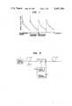
- the attenuation of the signal pulseis shown in FIG. 1, where the orthogonal axis indicates signal pulse level and the abscissa the length L of the fiber from a transmitting station.
- the alphabetic notation A 1denotes a first optical repeater and the notation A 2 a second optical repeater.
- the signal pulseis attenuated exponentially because of the loss in the fiber between the transmitting station and the first optical repeater A 1 .
- conversion of light-electricity-lightis carried out by the system described above, and the signal pulse is amplified.
- the signal pulse amplified at the first optical repeater A 1is again attenuated exponentially until it reaches the second optical repeater A 2 . The same process is repeated in the transmission to the receiving station.
- optical repeater of such prior art systemis provided with electric signal processing circuits which require a number of electric components, thereby increasing probability of trouble, it is less reliable.
- modulation of laser beam by the electric signalmight increase the width of the oscillation spectrum.
- the optical repeater of the present inventioncomprises a light source for providing a light of frequency ⁇ O , and a beam splitter such as a half mirror for synthesizing said light from said light source and a signal pulse including Stokes light corresponding to said frequency ⁇ O generated by Raman effect in the optical fibers, and the optical repeater system is characterized in that the signal pulses are amplified with induced Raman effect in the optical fiber caused by the light and dispersion characteristic of the optical fiber.
- FIG. 1is a characteristic curve which gives the relation between the signal pulse level and the fiber length of the prior art optical repeater.
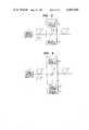
- FIG. 2is a brief illustration of the optical repeater which is an embodiment of this invention.
- FIG. 3is a timing chart for use in explanation of the amplification process of the signal light according to the present invention
- FIG. 3(a)showing wave forms of the pumping light (CW operation) and the signal light before being combined
- FIGS. 3(b) and 3(c)showing relationship between the signal light pulse and the pumping light when the former is amplified by the latter.
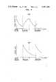
- FIG. 4(a)is a characteristic curve indicating the relation between the signal pulse level and the fiber length
- FIG. 4(b)is a characteristic curve indicating the relation between the pumping level and the fiber length of the optical repeater system of this invention.
- FIGS. 5 through 8are brief illustrations of other embodiments of this invention.
- FIG. 9is an illustration for use in explaining the distortion of a wave at the receiving station when a light wave containing a plurality of wavelengths is transmitted.
- FIGS. 9(a) and 9(b)respectively illustrating a pulse with several wavelengths before and after propagation through a fiber.
- FIG. 10shows further embodiment of this invention, which is an optical repeater system for optical communication, capable of shaping the distorted wave.
- Silica used as the material of the optical fiber itselfexhibits the Raman effect, and generates a first Stokes light having a wavelength of 1.12 ⁇ m, in the case of using a YAG laser oscillating with a wavelength of 1.06 ⁇ m.
- a weak light of several wattsscarcely causes Raman effect in ordinary condition, but within an optical fiber the light is concentrated in an optical guide of diameter less than 10 ⁇ m, so that even weak input light will have a large value of power density, or power per unit area.
- an optical fiber made of Raman substancehas a very long length, facilitating occurrence of the Raman phenomenon. It is already reported that several watts of light cause Raman effect within an optical fiber.
- the conversion efficiency of pumping light to the first Stokes lightis much enhanced when light having a frequency ⁇ O - ⁇ i (the first Stokes light) together with the pumping light is incident on a Raman substance. This phenomenon is termed induced Raman effect.
- This inventionapplies this induced Raman effect in an optical fiber to effect amplification of signal light.
- a signal light pulse 5(its frequency is ⁇ O - ⁇ i ), modulated at a transmitting station 1 and fed along optical fiber 2, enters an optical repeater 3, which has a light source 3a for emitting light at a frequency ⁇ O which is to be converted to a first Stokes light (frequency ⁇ O - ⁇ i ) in the optical fiber, and a beam splitter 3b consisting, for example, of a half-mirror.
- the signal light pulse 5 fed to the optical repeater 3is sent out over an optical fiber 4 after being synthesized at the beam splitter 3b with the pumping light having frequency ⁇ O emitted from the pumping light source 3a.
- the pumping light with its frequency ⁇ Osupplied from the pumping light source 3a, is efficiently converted, by the induced Raman effect of the fiber, to a signal pulse only when it is propagated together with the signal light pulse along the optical fiber 4. That means, the signal light pulse is amplified by the induced Raman effect of the fiber.
- FIG. 3(a)shows wave forms of the pumping light and the signal light pulse before it is synthesized at the beam splitter 3b shown in FIG. 2.
- These two lights synthesized at the beam splitter 3bpropagate at the same time through the optical fiber 4 and the signal light pulse is amplified by the induced Raman effect that occurs within the optical fiber as shown in FIG. 3(b).
- the energy level of the pumping lightis lowered because the energy therein is converted to that of the signal light pulse.
- the optical fiberhas dispersion characteristic, that is, the propagation velocity varies with the wavelength of light in the optical fiber. This is the reason why, in the existing optical fiber, there are velocity differences of about 1.5 nano seconds per kilometer between the signal light pulse of the wave length 1.12 ⁇ m and the pumping light of wavelength 1.06 ⁇ m. The positional relation between the pumping light and the signal light pulse is shifted as these lights travel as shown in FIG. 3(c).
- a time difference of 150 nsecis produced between the pumping light and the signal light pulse on the way from one repeater to next one. Since the inter-pulse time of the signal light pulses is about 3.3 n sec., about 45 pulses pass a certain point of the pumping light while they travel 100 Km.
- the signal light pulseprogresses with higher speed than the pumping light.
- the signal light pulsegains energy from the pumping light, therefore the level of the signal light pulse is raised as shown in FIG. 3(c), while the pumping light, giving its energy to the signal pulse, advances with lower speed than the signal light pulse, and hence its average energy level is lowered in the course of the propagation as shown in the figure.
- the pumping lightmay be oscillated continuously and not need to be modulated. Since almost all the energy of the continuously oscillated pumping light is contributed to the amplification of the signal light pulse, a high energy conversion efficiency can be expected.
- FIG. 4(a)depicts the energy level change of the signal light pulse in an optical repeater system of this invention.
- the orthogonal axisindicates signal pulse level
- the abscissa Lindicates the length of the optical fiber from the transmitting station.
- the signal light pulse sent from the transmitting stationloses its energy in the optical fiber and attenuates exponentially in proportion to the fiber length until it reaches the first repeater A 1 .
- the attenuated signal pulseis continuously amplified by the induced Raman effect in the optical fiber until it reaches a point A 2 which is spaced by a certain distance from the first optical repeater A 1 .
- the pumping light applied to the first optical repeater A 1is continuously attenuated because of the power migration to the signal light pulse and the loss in the optical fiber as shown in FIG. 4(b), and after the point A 2 , its energy level has been so reduced that it does not cause the induced Raman effect. Consequently, the signal light pulse (FIG. 4(a)), losing its energy due to the optical fiber, attenuates exponentially as it propagates from the point A 2 to the second optical repeater A 3 .
- FIG. 1 to FIG. 4(a)clearly shows that, in the conventional method, the amplification is carried out at a single point where an optical repeater is present, whereas in the present embodiment, the amplification is performed in the fiber extending from the optical repeater to a certain downstream point A 2 along the fiber.
- the calculated interval between adjacent optical repeaters A 1 and A 2is 120 Km, for such values as 1 watt of input pumping light to the optical fiber, 0.5 dB/Km of optical fiber loss, and 0.92 ⁇ 10 -11 cm/W of optical fiber Raman gain, and -40 dBm (1 ⁇ 10 -7 W) of signal pulse level in the first optical repeater A 1 .
- the light source 3cemits a pumping light at a frequency ⁇ 0 which is to be converted to a first Stokes light (frequency ⁇ O -- ⁇ i) in the optical fiber.
- This pumping lightintroduced by a beam splitter 3b consisting, for example, of a half mirror to the optical fiber 2, progresses toward the transmitting station 1.
- the signal light pulse 5having its frequency ⁇ O -- ⁇ i , generated at the transmitting station 1, propagates along the optical fiber 2 and advances toward the optical repeater 3.
- the signal light pulse 5therefore, meets with the pumping light in the optical fiber 2 so that it is amplified due to the Raman effect, as explained above.
- the induced Raman effect of the first embodimentis called a forward stimulated Raman effect because the signal light pulse travels in the same direction as the pumping light
- the induced Raman effect of the second embodimentis called a backward stimulated Raman effect because the signal light pulse travels in the opposite direction to the pumping light.
- FIG. 6shows a third embodiment of this invention.
- the induced Raman effect of this embodimentis a combination of a forward and a backward stimulated Raman effect.
- the first pumping light supplied from the first light source 3aenters the optical fiber 4 and travels in the forward direction along the optical fiber 4 as explained with respect to the first embodiment.
- the second pumping light from the second light source 3c entering the optical fiber 2travels in the backward direction along the optical fiber 2 as explained with respect to the second embodiment. Consequently, the signal light pulse 5 produced at the transmitting station 1 is amplified in both optical fibers 2 and 4.
- FIG. 7shows a fourth embodiment of this invention.
- This embodimentprovides a combination of a forward and a backward stimulated Raman effect as in said third embodiment, and utilizes a light reflection plate 3d such as a mirror or a prism to reflect the pumping light through the beam splitter 3b.
- FIG. 8shows a fifth embodiment of this invention, in which polarization elements 3e and 3d are inserted between the light sources 3a, 3c and the beam splitter 3b so as to prevent their mutual interference.
- the light source of the transmitting stationsupplies a single wave length in each embodiment of the optical repeater for the optical communication according to this invention mentioned above, no problem arises, but when the source supplies light containing plural wavelengths, the wave distortion of the signal light raises a problem.
- a light pulse a 1 given by a synthesis of a light pulse a 2 with its wave length ⁇ 1 and a light pulse a 3 with its wave length ⁇ 2is transmitted from a transmitting station for a long distance communication through an optical fiber
- the optical pulse b 1 received at the receiving stationis distorted because of the dispersion characteristic of the optical fiber as shown in FIG. 9(b).
- the wave distortion of the optical pulse b 1narrows the transmission band of the optical communication system.
- the optical communication system of FIG. 10where the numerical notation 1a denotes the light source of the transmitting station, the notations 6, 8 and 9 identify optical fibers, notation 7 identifies an optical equalizer, notation 10 identifies a receiving station, notation 10a identifies an optical detector, and the other notations indicate the same parts as those in FIG. 2.
- the distorted wave form of the signal light pulseis shaped to the pulses b 2 and b 3 of FIG. 9(b), by the optical equalizer 7 being added to the optical repeater system consisting of optical fibers 2, 4 and optical repeater 3.
- either of the shaped pulses b 2 and b 3may be used, thereby eliminating the inconvenience that the transmission bandwidth of the optical communication system is narrowed.
- the optical equalizerany existing light-electricity-light equalization methods are available.
- an optical equalizer 7is provided separately from the optical repeater 3, but the repeater 3 itself may have a light equalizing function.
- the low loss and the induced Raman effect of the optical fiberprovide an optical amplifier system so that no electric signal processing circuit is needed in the optical repeaters.
- the system of the present inventionis less probable to have optical repeater troubles, has no need to modulate the light of the optical repeater light source, and achieves a much more stable and reliable optical repeater system.
Landscapes
- Physics & Mathematics (AREA)
- Electromagnetism (AREA)
- Engineering & Computer Science (AREA)
- Computer Networks & Wireless Communication (AREA)
- Signal Processing (AREA)
- Plasma & Fusion (AREA)
- Optics & Photonics (AREA)
- Lasers (AREA)
- Optical Communication System (AREA)
Abstract
Description
Claims (5)
Applications Claiming Priority (2)
| Application Number | Priority Date | Filing Date | Title |
|---|---|---|---|
| JP55-068827 | 1980-05-26 | ||
| JP6882780AJPS56165437A (en) | 1980-05-26 | 1980-05-26 | Optical repeating system for optical communication |
Publications (1)
| Publication Number | Publication Date |
|---|---|
| US4401364Atrue US4401364A (en) | 1983-08-30 |
Family
ID=13384921
Family Applications (1)
| Application Number | Title | Priority Date | Filing Date |
|---|---|---|---|
| US06/260,463Expired - LifetimeUS4401364A (en) | 1980-05-26 | 1981-05-04 | Optical repeater system for optical communication |
Country Status (3)
| Country | Link |
|---|---|
| US (1) | US4401364A (en) |
| JP (1) | JPS56165437A (en) |
| GB (1) | GB2077909B (en) |
Cited By (48)
| Publication number | Priority date | Publication date | Assignee | Title |
|---|---|---|---|---|
| US4616898A (en)* | 1980-03-31 | 1986-10-14 | Polaroid Corporation | Optical communication systems using raman repeaters and components therefor |
| EP0186299A3 (en)* | 1984-12-13 | 1987-03-18 | Stc Plc | Optical amplifier |
| US4699452A (en)* | 1985-10-28 | 1987-10-13 | American Telephone And Telegraph Company, At&T Bell Laboratories | Optical communications system comprising Raman amplification means |
| US4708421A (en)* | 1985-02-08 | 1987-11-24 | The Board Of Trustees Of The Leland Stanford Junior University | In-line fiber optic memory |
| US4720684A (en)* | 1983-12-16 | 1988-01-19 | Standard Telephones And Cables Plc | Optical amplifier |
| US4738503A (en)* | 1985-02-08 | 1988-04-19 | The Board Of Trustees Of The Leland Stanford Junion University | In-line fiber optic memory |
| USH499H (en) | 1986-09-02 | 1988-07-05 | The United States Of America As Represented By The United States Department Of Energy | System and method for linearly amplifying optical analog signals by backward Raman scattering |
| US4784450A (en)* | 1984-10-15 | 1988-11-15 | Hughes Aircraft Company | Apparatus for generating and amplifying new wavelengths of optical radiation |
| US4786140A (en)* | 1987-10-30 | 1988-11-22 | Gte Laboratories Incorporated | Method of modulating large-power light beams using fiber raman amplification |
| US4790619A (en)* | 1986-04-25 | 1988-12-13 | American Telephone And Telegraph Company, At&T Bell Laboratories | Apparatus comprising Raman-active optical fiber |
| US4794598A (en)* | 1986-07-18 | 1988-12-27 | The Board Of Trustees Of The Leland Stanford Junior University | Synchronously pumped ring fiber Raman laser |
| US4805977A (en)* | 1986-11-04 | 1989-02-21 | Oki Electric Industry Co., Ltd | Optical coupler for optical direct amplifier |
| US4815804A (en)* | 1985-02-08 | 1989-03-28 | The Board Of Trustees Of The Leland Stanford Junior University | In-line fiber optic memory and method of using same |
| US4820018A (en)* | 1987-10-30 | 1989-04-11 | Gte Laboratories Incorporated | Optical fiber for light amplification |
| US4977620A (en)* | 1985-05-09 | 1990-12-11 | British Telecommunications Plc | Optical homodyne detection |
| US5208699A (en)* | 1991-12-20 | 1993-05-04 | Hughes Aircraft Company | Compensated, SBS-free optical beam amplification and delivery apparatus and method |
| US6115174A (en)* | 1998-07-21 | 2000-09-05 | Corvis Corporation | Optical signal varying devices |
| US6344922B1 (en) | 1998-07-21 | 2002-02-05 | Corvis Corporation | Optical signal varying devices |
| US6344925B1 (en) | 2000-03-03 | 2002-02-05 | Corvis Corporation | Optical systems and methods and optical amplifiers for use therein |
| US6356383B1 (en) | 1999-04-02 | 2002-03-12 | Corvis Corporation | Optical transmission systems including optical amplifiers apparatuses and methods |
| US20020044324A1 (en)* | 2000-08-25 | 2002-04-18 | Fujitsu Limited | Optical communication system, method for supplying pump light, and distributed raman amplifying apparatus |
| US6433922B1 (en) | 2001-02-26 | 2002-08-13 | Redc Optical Networks Ltd. | Apparatus and method for a self adjusting Raman amplifier |
| US6441951B1 (en) | 2000-09-07 | 2002-08-27 | Fujitsu Limited | Optical amplification apparatus using Raman amplification |
| US20020154359A1 (en)* | 2000-08-31 | 2002-10-24 | Fujitsu Limited | Method of activating optical communication system, channel increasing/decreasing method, and computer-readable recording medium |
| US20020159133A1 (en)* | 2001-02-02 | 2002-10-31 | The Furukawa Electric Co., Ltd. | Pump light source for raman amplifier and raman amplifier using the same |
| US20020176133A1 (en)* | 1999-10-22 | 2002-11-28 | Corvis Corporation | Method of adjusting power for a wavelength-division multiplexed optical transmission system |
| US6510000B1 (en) | 2000-08-31 | 2003-01-21 | Fujitsu Limited | Optical amplifier for wide band raman amplification of wavelength division multiplexed (WDM) signal lights |
| GB2378832A (en)* | 2001-08-14 | 2003-02-19 | Fujitsu Ltd | Remote optical repeater monitoring |
| US6532102B2 (en) | 2001-02-22 | 2003-03-11 | Fujitsu Limited | Optical amplifier |
| US20030063373A1 (en)* | 2000-01-14 | 2003-04-03 | The Furukawa Electric Co., Ltd. | Raman amplifier |
| US20030072062A1 (en)* | 2001-10-03 | 2003-04-17 | Bo Pedersen | High power repeaters for raman amplified, wave division multiplexed optical communication systems |
| US20030072063A1 (en)* | 2001-10-03 | 2003-04-17 | Adams Robert M. | High density optical packaging |
| US20030142394A1 (en)* | 2002-01-16 | 2003-07-31 | Bianca Buchold | Method and contrivance for applying a Raman amplification in a transmission and/or fibre device |
| US6614586B2 (en) | 2001-07-30 | 2003-09-02 | Dorsal Networks, Inc. | Methods and systems for high performance, wide bandwidth optical communication systems using Raman amplification |
| US6618195B2 (en) | 2001-04-20 | 2003-09-09 | Dorsal Networks Inc. | Pump assembly employing coupled radiation sources for multiple fibers |
| US6624926B1 (en) | 2000-08-25 | 2003-09-23 | Fujitsu Limited | Optical amplifier with pump light source control for raman amplification |
| US6633697B2 (en) | 1999-05-31 | 2003-10-14 | Ther Furukawa Electric Co., Ltd. | Raman amplification method and optical signal transmission method using same |
| US6671429B2 (en) | 2001-10-03 | 2003-12-30 | Dorsal Networks, Inc. | Balanced coupler for radiation sources |
| US6687047B2 (en) | 2001-05-29 | 2004-02-03 | Dorsal Networks, Inc. | Shared forward pumping in optical communications network |
| US20040066550A1 (en)* | 2002-10-02 | 2004-04-08 | Jay Paul R. | Optical pulse reshaping system |
| US6775057B2 (en) | 1998-07-23 | 2004-08-10 | The Furukawa Electric Co., Ltd. | Raman amplifier, optical repeater, and raman amplification method |
| US6782209B2 (en) | 2000-03-03 | 2004-08-24 | Corvis Corporation | Optical transmission systems including optical amplifiers and methods |
| US6798801B2 (en) | 2001-10-03 | 2004-09-28 | Dorsal Networks, Inc. | Pump laser current driver |
| US20040213510A1 (en)* | 1999-10-22 | 2004-10-28 | Corvis Corporation | Optical fiber transmission system using RZ pulses |
| US6839522B2 (en) | 1998-07-21 | 2005-01-04 | Corvis Corporation | Optical signal varying devices, systems and methods |
| US6873455B2 (en) | 2000-08-30 | 2005-03-29 | Fujitsu Limited | Optical amplification apparatus utilizing raman amplification and controlling method thereof |
| US20050213985A1 (en)* | 1999-05-24 | 2005-09-29 | Corvis Corporation | Optical transmission systems including optical amplifiers and methods of use therein |
| US7039325B2 (en) | 2001-03-06 | 2006-05-02 | Fujitsu Limited | Communication system |
Families Citing this family (7)
| Publication number | Priority date | Publication date | Assignee | Title |
|---|---|---|---|---|
| JPS5853243A (en)* | 1981-09-25 | 1983-03-29 | Nippon Telegr & Teleph Corp <Ntt> | Light transmitting system |
| GB2116391B (en)* | 1982-02-25 | 1985-08-14 | Western Electric Co | Single-mode optical fibre telecommunication apparatus |
| JPS59126696A (en)* | 1983-01-10 | 1984-07-21 | Nec Corp | Light amplifier for optical communication |
| JPS6114624A (en)* | 1984-06-29 | 1986-01-22 | Nippon Telegr & Teleph Corp <Ntt> | Optical amplifying device by optical fiber |
| JP2692694B2 (en)* | 1987-05-25 | 1997-12-17 | 日本電信電話株式会社 | Optical fiber laser device |
| JP3137632B2 (en)* | 1989-08-31 | 2001-02-26 | 富士通株式会社 | Optical communication system with optical fiber amplifier |
| US5229876A (en)* | 1990-03-26 | 1993-07-20 | At&T Bell Laboratories | Telemetry for optical fiber amplifier repeater |
Citations (4)
| Publication number | Priority date | Publication date | Assignee | Title |
|---|---|---|---|---|
| US4068952A (en)* | 1976-07-23 | 1978-01-17 | Hughes Aircraft Company | Range testing system having simulated optical targets |
| US4136929A (en)* | 1974-11-29 | 1979-01-30 | Hitachi, Ltd. | Apparatus for generating light pulse train |
| US4166212A (en)* | 1977-06-03 | 1979-08-28 | International Standard Electric Corporation | Recirculating optical delay line |
| US4261639A (en)* | 1979-11-13 | 1981-04-14 | Bell Telephone Laboratories, Incorporated | Optical pulse equalization in single-mode fibers |
Family Cites Families (2)
| Publication number | Priority date | Publication date | Assignee | Title |
|---|---|---|---|---|
| BE789175A (en)* | 1971-09-24 | 1973-01-15 | Siemens Ag | INTERMEDIATE AMPLIFIER FOR AN INFORMATION TRANSMISSION SYSTEM |
| US3705992A (en)* | 1971-12-13 | 1972-12-12 | Bell Telephone Labor Inc | Broadband tunable raman-effect devices in optical fibers |
- 1980
- 1980-05-26JPJP6882780Apatent/JPS56165437A/enactiveGranted
- 1981
- 1981-05-04USUS06/260,463patent/US4401364A/ennot_activeExpired - Lifetime
- 1981-05-12GBGB8114457Apatent/GB2077909B/ennot_activeExpired
Patent Citations (4)
| Publication number | Priority date | Publication date | Assignee | Title |
|---|---|---|---|---|
| US4136929A (en)* | 1974-11-29 | 1979-01-30 | Hitachi, Ltd. | Apparatus for generating light pulse train |
| US4068952A (en)* | 1976-07-23 | 1978-01-17 | Hughes Aircraft Company | Range testing system having simulated optical targets |
| US4166212A (en)* | 1977-06-03 | 1979-08-28 | International Standard Electric Corporation | Recirculating optical delay line |
| US4261639A (en)* | 1979-11-13 | 1981-04-14 | Bell Telephone Laboratories, Incorporated | Optical pulse equalization in single-mode fibers |
Cited By (97)
| Publication number | Priority date | Publication date | Assignee | Title |
|---|---|---|---|---|
| US4616898A (en)* | 1980-03-31 | 1986-10-14 | Polaroid Corporation | Optical communication systems using raman repeaters and components therefor |
| US4720684A (en)* | 1983-12-16 | 1988-01-19 | Standard Telephones And Cables Plc | Optical amplifier |
| US4784450A (en)* | 1984-10-15 | 1988-11-15 | Hughes Aircraft Company | Apparatus for generating and amplifying new wavelengths of optical radiation |
| US4740974A (en)* | 1984-12-13 | 1988-04-26 | Stc Plc | Optical amplifiers |
| EP0186299A3 (en)* | 1984-12-13 | 1987-03-18 | Stc Plc | Optical amplifier |
| US4708421A (en)* | 1985-02-08 | 1987-11-24 | The Board Of Trustees Of The Leland Stanford Junior University | In-line fiber optic memory |
| US4738503A (en)* | 1985-02-08 | 1988-04-19 | The Board Of Trustees Of The Leland Stanford Junion University | In-line fiber optic memory |
| US4815804A (en)* | 1985-02-08 | 1989-03-28 | The Board Of Trustees Of The Leland Stanford Junior University | In-line fiber optic memory and method of using same |
| US4977620A (en)* | 1985-05-09 | 1990-12-11 | British Telecommunications Plc | Optical homodyne detection |
| US4699452A (en)* | 1985-10-28 | 1987-10-13 | American Telephone And Telegraph Company, At&T Bell Laboratories | Optical communications system comprising Raman amplification means |
| US4790619A (en)* | 1986-04-25 | 1988-12-13 | American Telephone And Telegraph Company, At&T Bell Laboratories | Apparatus comprising Raman-active optical fiber |
| US4794598A (en)* | 1986-07-18 | 1988-12-27 | The Board Of Trustees Of The Leland Stanford Junior University | Synchronously pumped ring fiber Raman laser |
| USH499H (en) | 1986-09-02 | 1988-07-05 | The United States Of America As Represented By The United States Department Of Energy | System and method for linearly amplifying optical analog signals by backward Raman scattering |
| US4805977A (en)* | 1986-11-04 | 1989-02-21 | Oki Electric Industry Co., Ltd | Optical coupler for optical direct amplifier |
| US4820018A (en)* | 1987-10-30 | 1989-04-11 | Gte Laboratories Incorporated | Optical fiber for light amplification |
| US4786140A (en)* | 1987-10-30 | 1988-11-22 | Gte Laboratories Incorporated | Method of modulating large-power light beams using fiber raman amplification |
| US5208699A (en)* | 1991-12-20 | 1993-05-04 | Hughes Aircraft Company | Compensated, SBS-free optical beam amplification and delivery apparatus and method |
| US7046430B2 (en) | 1998-07-21 | 2006-05-16 | Corvis Corporation | Optical transmission systems including signal varying devices and methods |
| US6115174A (en)* | 1998-07-21 | 2000-09-05 | Corvis Corporation | Optical signal varying devices |
| US6282002B1 (en) | 1998-07-21 | 2001-08-28 | Corvis Corporation | Optical signal varying devices |
| US6344922B1 (en) | 1998-07-21 | 2002-02-05 | Corvis Corporation | Optical signal varying devices |
| US6775056B2 (en) | 1998-07-21 | 2004-08-10 | Corvis Corporation | Optical transmission systems including signal varying devices and methods |
| US6839522B2 (en) | 1998-07-21 | 2005-01-04 | Corvis Corporation | Optical signal varying devices, systems and methods |
| US6377389B1 (en) | 1998-07-21 | 2002-04-23 | Corvis Corporation | Optical signal varying devices |
| US20050046929A1 (en)* | 1998-07-21 | 2005-03-03 | Corvis Corporation | Optical transmission systems including signal varying devices and methods |
| US7548368B2 (en) | 1998-07-23 | 2009-06-16 | The Furukawa Electric Co., Ltd. | Raman amplifier, optical repeater, and raman amplification method |
| US20110141553A1 (en)* | 1998-07-23 | 2011-06-16 | Furukawa Electric Co., Ltd. | Raman amplifier, optical repeater, and raman amplification method |
| US7692852B2 (en) | 1998-07-23 | 2010-04-06 | The Furukawa Electric Co., Ltd. | Raman amplifier, optical repeater, and Raman amplification method |
| US20040190909A1 (en)* | 1998-07-23 | 2004-09-30 | The Furukawa Electric Co., Ltd. | Raman amplifier, optical repeater, and raman amplification method |
| US8437074B2 (en) | 1998-07-23 | 2013-05-07 | Furukawa Electric Co., Ltd. | Raman amplifier, optical repeater, and Raman amplification method |
| US20070247701A1 (en)* | 1998-07-23 | 2007-10-25 | The Furukawa Electric Co., Ltd. | Raman amplifier, optical repeater, and raman amplification method |
| US9281654B2 (en) | 1998-07-23 | 2016-03-08 | Furukawa Electric Co., Ltd. | Raman amplifier, optical repeater, and Raman amplification method |
| US6775057B2 (en) | 1998-07-23 | 2004-08-10 | The Furukawa Electric Co., Ltd. | Raman amplifier, optical repeater, and raman amplification method |
| US20040264968A1 (en)* | 1999-04-02 | 2004-12-30 | Corvis Corporation | Optical transmission systems including optical amplifiers, apparatuses and methods |
| US6771413B2 (en) | 1999-04-02 | 2004-08-03 | Corvis Corporation | Optical transmission systems including optical amplifiers, apparatuses and methods |
| US6356383B1 (en) | 1999-04-02 | 2002-03-12 | Corvis Corporation | Optical transmission systems including optical amplifiers apparatuses and methods |
| US7133193B2 (en) | 1999-04-02 | 2006-11-07 | Corvis Corporation | Optical transmission systems including optical amplifiers, apparatuses and methods |
| US7085042B2 (en) | 1999-05-24 | 2006-08-01 | Corvis Corporation | Optical transmission systems including optical amplifiers and methods of use therein |
| US20050213985A1 (en)* | 1999-05-24 | 2005-09-29 | Corvis Corporation | Optical transmission systems including optical amplifiers and methods of use therein |
| US6882467B1 (en) | 1999-05-31 | 2005-04-19 | The Furukawa Electric Co., Ltd. | Raman amplification method and optical signal transmission method using the same |
| US6633697B2 (en) | 1999-05-31 | 2003-10-14 | Ther Furukawa Electric Co., Ltd. | Raman amplification method and optical signal transmission method using same |
| US20050078352A1 (en)* | 1999-05-31 | 2005-04-14 | The Furukawa Electric Co., Ltd. | Raman amplification method and optical signal transmission method using same |
| US20020176133A1 (en)* | 1999-10-22 | 2002-11-28 | Corvis Corporation | Method of adjusting power for a wavelength-division multiplexed optical transmission system |
| US6941037B2 (en) | 1999-10-22 | 2005-09-06 | Corvis Algety Sa | Optical fiber transmission system using RZ pulses |
| US20040213510A1 (en)* | 1999-10-22 | 2004-10-28 | Corvis Corporation | Optical fiber transmission system using RZ pulses |
| US7127173B2 (en) | 1999-10-22 | 2006-10-24 | Corvis Algety Sa | Method of adjusting power for a wavelength-division multiplexed optical transmission system |
| US6825972B2 (en) | 2000-01-14 | 2004-11-30 | The Furukawa Electric Co., Ltd. | Raman amplifier |
| US6882468B2 (en) | 2000-01-14 | 2005-04-19 | The Furukawa Electric Co., Ltd. | Raman amplifier |
| US20040051937A1 (en)* | 2000-01-14 | 2004-03-18 | The Furukawa Electric Co., Ltd. | Raman amplifier |
| US20050157379A1 (en)* | 2000-01-14 | 2005-07-21 | The Furukawa Electric Co. Ltd. | Raman amplifier |
| US7050221B2 (en) | 2000-01-14 | 2006-05-23 | The Furukawa Electric Co., Ltd. | Raman amplifier |
| US20030063373A1 (en)* | 2000-01-14 | 2003-04-03 | The Furukawa Electric Co., Ltd. | Raman amplifier |
| US7010229B2 (en) | 2000-03-03 | 2006-03-07 | Corvis Corporation | Optical transmission systems including optical amplifiers and methods |
| US6782209B2 (en) | 2000-03-03 | 2004-08-24 | Corvis Corporation | Optical transmission systems including optical amplifiers and methods |
| US6344925B1 (en) | 2000-03-03 | 2002-02-05 | Corvis Corporation | Optical systems and methods and optical amplifiers for use therein |
| US20040253001A1 (en)* | 2000-03-03 | 2004-12-16 | Corvis Corporation | Optical transmission systems including optical amplifiers and methods |
| US6704139B2 (en) | 2000-03-03 | 2004-03-09 | Corvis Corporation | Optical systems and methods and optical amplifiers for use therein |
| US6459529B1 (en) | 2000-03-03 | 2002-10-01 | Corvis Corporation | Optical systems and methods and optical amplifiers for use therein |
| US20040080813A1 (en)* | 2000-08-25 | 2004-04-29 | Fujitsu Limited | Optical amplifier with pump light source control for Raman amplification |
| US7362499B2 (en) | 2000-08-25 | 2008-04-22 | Fujitsu Limited | Optical amplifier with pump light source control for Raman amplification |
| US20020044324A1 (en)* | 2000-08-25 | 2002-04-18 | Fujitsu Limited | Optical communication system, method for supplying pump light, and distributed raman amplifying apparatus |
| US7042636B2 (en) | 2000-08-25 | 2006-05-09 | Fujitsu Limited | Optical amplifier with pump light source control for Raman amplification |
| US7233742B2 (en) | 2000-08-25 | 2007-06-19 | Fujitsu Limited | Optical communication system, method for supplying pump light, and distributed Raman amplifying apparatus |
| US6624926B1 (en) | 2000-08-25 | 2003-09-23 | Fujitsu Limited | Optical amplifier with pump light source control for raman amplification |
| US20050024714A1 (en)* | 2000-08-25 | 2005-02-03 | Fujitsu Limited | Optical amplifier with pump light source control for Raman amplification |
| US6891661B2 (en) | 2000-08-25 | 2005-05-10 | Fujitsu Limited | Optical amplifier with pump light source control for Raman amplification |
| US6873455B2 (en) | 2000-08-30 | 2005-03-29 | Fujitsu Limited | Optical amplification apparatus utilizing raman amplification and controlling method thereof |
| US7394589B2 (en) | 2000-08-31 | 2008-07-01 | Fujitsu Limited | Optical amplifier for wide band Raman amplification of wavelength division multiplexed (WDM) signal lights |
| US20020154359A1 (en)* | 2000-08-31 | 2002-10-24 | Fujitsu Limited | Method of activating optical communication system, channel increasing/decreasing method, and computer-readable recording medium |
| US6510000B1 (en) | 2000-08-31 | 2003-01-21 | Fujitsu Limited | Optical amplifier for wide band raman amplification of wavelength division multiplexed (WDM) signal lights |
| US6839160B2 (en) | 2000-08-31 | 2005-01-04 | Fujitsu Limited | Method of activating optical communication system, channel increasing/decreasing method, and computer-readable recording medium |
| US6683712B2 (en) | 2000-09-07 | 2004-01-27 | Fujitsu Limited | Optical amplification apparatus using Raman amplification |
| US6441951B1 (en) | 2000-09-07 | 2002-08-27 | Fujitsu Limited | Optical amplification apparatus using Raman amplification |
| US6847478B1 (en) | 2000-09-07 | 2005-01-25 | Fujitsu Limited | Optical amplification apparatus using Raman amplification |
| US20020159133A1 (en)* | 2001-02-02 | 2002-10-31 | The Furukawa Electric Co., Ltd. | Pump light source for raman amplifier and raman amplifier using the same |
| US6950230B2 (en) | 2001-02-02 | 2005-09-27 | The Furukawa Electric Co., Ltd. | Pump light source for Raman amplifier and Raman amplifier using the same |
| US6532102B2 (en) | 2001-02-22 | 2003-03-11 | Fujitsu Limited | Optical amplifier |
| US6433922B1 (en) | 2001-02-26 | 2002-08-13 | Redc Optical Networks Ltd. | Apparatus and method for a self adjusting Raman amplifier |
| US6519082B2 (en) | 2001-02-26 | 2003-02-11 | Redc Optical Networks Ltd. | Apparatus and method for a self-adjusting Raman amplifier |
| US7039325B2 (en) | 2001-03-06 | 2006-05-02 | Fujitsu Limited | Communication system |
| US20040042064A1 (en)* | 2001-04-20 | 2004-03-04 | Dorsal Networks, Inc. | Pump assembly employing coupled radiation sources for multiple fibers |
| US6618195B2 (en) | 2001-04-20 | 2003-09-09 | Dorsal Networks Inc. | Pump assembly employing coupled radiation sources for multiple fibers |
| US6894831B2 (en) | 2001-04-20 | 2005-05-17 | Dorsal Networks, Inc. | Pump assembly employing coupled radiation sources for multiple fibers |
| US6687047B2 (en) | 2001-05-29 | 2004-02-03 | Dorsal Networks, Inc. | Shared forward pumping in optical communications network |
| US6614586B2 (en) | 2001-07-30 | 2003-09-02 | Dorsal Networks, Inc. | Methods and systems for high performance, wide bandwidth optical communication systems using Raman amplification |
| GB2378832A (en)* | 2001-08-14 | 2003-02-19 | Fujitsu Ltd | Remote optical repeater monitoring |
| GB2378832B (en)* | 2001-08-14 | 2004-12-15 | Fujitsu Ltd | Optical transmission system |
| US6980745B2 (en) | 2001-08-14 | 2005-12-27 | Fujitsu Limited | Optical transmission system |
| US7196838B2 (en) | 2001-10-03 | 2007-03-27 | Dorsal Networks, Inc. | High density optical packaging |
| US7120362B2 (en) | 2001-10-03 | 2006-10-10 | Bo Pedersen | High power repeaters for Raman amplified, wave division multiplexed optical communication systems |
| US20030072062A1 (en)* | 2001-10-03 | 2003-04-17 | Bo Pedersen | High power repeaters for raman amplified, wave division multiplexed optical communication systems |
| US20030072063A1 (en)* | 2001-10-03 | 2003-04-17 | Adams Robert M. | High density optical packaging |
| US6671429B2 (en) | 2001-10-03 | 2003-12-30 | Dorsal Networks, Inc. | Balanced coupler for radiation sources |
| US6798801B2 (en) | 2001-10-03 | 2004-09-28 | Dorsal Networks, Inc. | Pump laser current driver |
| US7342711B2 (en) | 2002-01-16 | 2008-03-11 | Lucent Technologies Inc. | Method and contrivance for applying a Raman amplification in a transmission and/or fibre device |
| US20030142394A1 (en)* | 2002-01-16 | 2003-07-31 | Bianca Buchold | Method and contrivance for applying a Raman amplification in a transmission and/or fibre device |
| US20040066550A1 (en)* | 2002-10-02 | 2004-04-08 | Jay Paul R. | Optical pulse reshaping system |
Also Published As
| Publication number | Publication date |
|---|---|
| JPS6258558B2 (en) | 1987-12-07 |
| GB2077909A (en) | 1981-12-23 |
| GB2077909B (en) | 1984-06-20 |
| JPS56165437A (en) | 1981-12-19 |
Similar Documents
| Publication | Publication Date | Title |
|---|---|---|
| US4401364A (en) | Optical repeater system for optical communication | |
| US4699452A (en) | Optical communications system comprising Raman amplification means | |
| US4881790A (en) | Optical communications system comprising raman amplification means | |
| JP3137632B2 (en) | Optical communication system with optical fiber amplifier | |
| US6178038B1 (en) | Optical amplifier having an improved noise figure | |
| US6452716B1 (en) | Amplitude modulation of a pump laser signal in a distributed raman amplifier | |
| US6282017B1 (en) | Optical communication system and optical amplifier | |
| EP1323217B1 (en) | Wide bandwidth fiber raman amplifier | |
| JP2000151507A (en) | Optical transmission system | |
| US5566018A (en) | Apparatus for adjusting channel width of multi-channel fiber amplifier light source | |
| US20030142392A1 (en) | Hybrid brillouin/erbium doped fiber amplifier apparatus and method | |
| US5283687A (en) | Amplifier for optical fiber communication link | |
| US6025948A (en) | Optical signal transmission installation including a repeater monitoring system | |
| JPH09197452A (en) | Optical fiber communication system | |
| US5436751A (en) | Analog optical transmission system and optical fiber amplifier | |
| JPS61119087A (en) | Optical communication method and apparatus | |
| WO1998016018A2 (en) | Wavelength division multiplexed signal amplifier | |
| JP2907083B2 (en) | Optical transmission method and optical transmission device | |
| US7924496B2 (en) | Apparatus and method for Raman gain control | |
| Sugie et al. | A novel repeaterless CPFSK coherent lightwave system employing an optical booster amplifier | |
| JPH10221656A (en) | Optical transmitter and optical transmission method | |
| JP3195237B2 (en) | Optical transmission device, optical communication system, and method for amplifying input optical signal | |
| JPH0685367A (en) | Optical communication system | |
| JP3153127B2 (en) | Optical transmission device, optical communication system, and method for amplifying optical signal | |
| JPS6397026A (en) | Method and device for optical communication |
Legal Events
| Date | Code | Title | Description |
|---|---|---|---|
| AS | Assignment | Owner name:KOKUSAI DENSHIN DENWA KABUSHIKI KAISHA, 2-3-2 NISH Free format text:ASSIGNMENT OF ASSIGNORS INTEREST.;ASSIGNOR:MOCHIZUKI KIYOFUMI;REEL/FRAME:003882/0573 Effective date:19810409 Owner name:KOKUSAI DENSHIN DENWA KABUSHIKI KAISHA, JAPAN Free format text:ASSIGNMENT OF ASSIGNORS INTEREST;ASSIGNOR:MOCHIZUKI KIYOFUMI;REEL/FRAME:003882/0573 Effective date:19810409 | |
| STCF | Information on status: patent grant | Free format text:PATENTED CASE | |
| MAFP | Maintenance fee payment | Free format text:PAYMENT OF MAINTENANCE FEE, 4TH YEAR, PL 96-517 (ORIGINAL EVENT CODE: M170); ENTITY STATUS OF PATENT OWNER: LARGE ENTITY Year of fee payment:4 | |
| MAFP | Maintenance fee payment | Free format text:PAYMENT OF MAINTENANCE FEE, 8TH YEAR, PL 96-517 (ORIGINAL EVENT CODE: M171); ENTITY STATUS OF PATENT OWNER: LARGE ENTITY Year of fee payment:8 | |
| FEPP | Fee payment procedure | Free format text:PAYOR NUMBER ASSIGNED (ORIGINAL EVENT CODE: ASPN); ENTITY STATUS OF PATENT OWNER: LARGE ENTITY | |
| MAFP | Maintenance fee payment | Free format text:PAYMENT OF MAINTENANCE FEE, 12TH YEAR, LARGE ENTITY (ORIGINAL EVENT CODE: M185); ENTITY STATUS OF PATENT OWNER: LARGE ENTITY Year of fee payment:12 |