US4401272A - Aerosol fan sprayhead - Google Patents
Aerosol fan sprayheadDownload PDFInfo
- Publication number
- US4401272A US4401272AUS06/378,789US37878982AUS4401272AUS 4401272 AUS4401272 AUS 4401272AUS 37878982 AUS37878982 AUS 37878982AUS 4401272 AUS4401272 AUS 4401272A
- Authority
- US
- United States
- Prior art keywords
- sprayhead
- outlet
- aerosol container
- orifice
- passageway
- Prior art date
- Legal status (The legal status is an assumption and is not a legal conclusion. Google has not performed a legal analysis and makes no representation as to the accuracy of the status listed.)
- Expired - Lifetime
Links
- 239000000443aerosolSubstances0.000titleclaimsabstractdescription38
- 239000007921spraySubstances0.000claimsabstractdescription42
- 239000000853adhesiveSubstances0.000claimsdescription18
- 230000001070adhesive effectEffects0.000claimsdescription18
- 229920000642polymerPolymers0.000claimsdescription6
- 239000003380propellantSubstances0.000claimsdescription4
- 239000002904solventSubstances0.000claimsdescription2
- 230000000881depressing effectEffects0.000claims1
- 239000012530fluidSubstances0.000claims1
- 239000000463materialSubstances0.000description10
- 239000007787solidSubstances0.000description7
- YMWUJEATGCHHMB-UHFFFAOYSA-NDichloromethaneChemical compoundClCClYMWUJEATGCHHMB-UHFFFAOYSA-N0.000description6
- 229920001971elastomerPolymers0.000description5
- 229920003023plasticPolymers0.000description4
- 239000004033plasticSubstances0.000description4
- 229920001084poly(chloroprene)Polymers0.000description4
- 238000005507sprayingMethods0.000description4
- 230000000712assemblyEffects0.000description3
- 238000000429assemblyMethods0.000description3
- 239000006185dispersionSubstances0.000description3
- 239000000806elastomerSubstances0.000description3
- 238000009472formulationMethods0.000description3
- 238000003801millingMethods0.000description3
- 239000000203mixtureSubstances0.000description3
- LCGLNKUTAGEVQW-UHFFFAOYSA-NDimethyl etherChemical compoundCOCLCGLNKUTAGEVQW-UHFFFAOYSA-N0.000description2
- 238000010276constructionMethods0.000description2
- 239000011888foilSubstances0.000description2
- 239000004615ingredientSubstances0.000description2
- CPLXHLVBOLITMK-UHFFFAOYSA-Nmagnesium oxideInorganic materials[Mg]=OCPLXHLVBOLITMK-UHFFFAOYSA-N0.000description2
- 239000005060rubberSubstances0.000description2
- 239000004821Contact adhesiveSubstances0.000description1
- 229920000459Nitrile rubberPolymers0.000description1
- 238000004026adhesive bondingMethods0.000description1
- 229920005549butyl rubberPolymers0.000description1
- 229920006037cross link polymerPolymers0.000description1
- 230000000994depressogenic effectEffects0.000description1
- 229920000578graft copolymerPolymers0.000description1
- 239000000395magnesium oxideSubstances0.000description1
- AXZKOIWUVFPNLO-UHFFFAOYSA-Nmagnesium;oxygen(2-)Chemical compound[O-2].[Mg+2]AXZKOIWUVFPNLO-UHFFFAOYSA-N0.000description1
- 239000002184metalSubstances0.000description1
- 229910052751metalInorganic materials0.000description1
- 230000004048modificationEffects0.000description1
- 238000012986modificationMethods0.000description1
- 229920001568phenolic resinPolymers0.000description1
- 239000005011phenolic resinSubstances0.000description1
- 239000000126substanceSubstances0.000description1
- -1t-Butyl phenolic resinChemical compound0.000description1
- 238000011144upstream manufacturingMethods0.000description1
- XLYOFNOQVPJJNP-UHFFFAOYSA-NwaterSubstancesOXLYOFNOQVPJJNP-UHFFFAOYSA-N0.000description1
- 238000003466weldingMethods0.000description1
Images


Classifications
- B—PERFORMING OPERATIONS; TRANSPORTING
- B65—CONVEYING; PACKING; STORING; HANDLING THIN OR FILAMENTARY MATERIAL
- B65D—CONTAINERS FOR STORAGE OR TRANSPORT OF ARTICLES OR MATERIALS, e.g. BAGS, BARRELS, BOTTLES, BOXES, CANS, CARTONS, CRATES, DRUMS, JARS, TANKS, HOPPERS, FORWARDING CONTAINERS; ACCESSORIES, CLOSURES, OR FITTINGS THEREFOR; PACKAGING ELEMENTS; PACKAGES
- B65D83/00—Containers or packages with special means for dispensing contents
- B65D83/14—Containers for dispensing liquid or semi-liquid contents by internal gaseous pressure, i.e. aerosol containers comprising propellant
- B65D83/28—Nozzles, nozzle fittings or accessories specially adapted therefor
- B65D83/30—Nozzles, nozzle fittings or accessories specially adapted therefor for guiding the flow of the dispensed content, e.g. funnels or hoods
- B65D83/303—Nozzles, nozzle fittings or accessories specially adapted therefor for guiding the flow of the dispensed content, e.g. funnels or hoods using extension tubes located in or at the nozzle outlets
Definitions
- This inventionrelates to aerosol sprayheads and, in particular, sprayheads utilized to dispense cohesive polymer solutions in a fan spray pattern.
- Dispersions of elastomershave been sold in aerosol containers equipped with fan sprayheads. It is desirable, however, to be able to spray solutions of elastomers, as opposed to dispersions, because dispersions pose a settling problem which is not encountered with solutions, and because soluble polymers offer higher adhesion strengths and resist elevated temperatures better than crosslinked polymers.
- U.S. application Ser. No. 282,243assigned to the assignee of the present invention, and incorporated herein, disclosed an aerosol sprayhead nozzle structure which enabled the formulation of aerosol adhesives based on soluble elastomers which, in turn, produced approximately two and one-half times the area coverage as compared to the best commercially available aerosol fan sprayhead.
- the sprayhead of U.S. Ser. No. 282,243permitted an aerosol solids level as high as 11.1 percent, which would provide enough adhesive in a 16 fl. oz.
- the improved nozzle structurepermits adhesives in solution to be sprayed in an acceptable pattern at typical aerosol container pressures of between approximately mately 20 psi (0.14 megapascals) and 100 psi (0.69 megapascals), as opposed to the approximately 2,000 psi (13.8 megapascals) necessary when such solutions of elastomeric adhesives are sprayed using airless spray gun equipment. It is thought that this ability to spray at low pressures and the dramatic difference in pressures is at least partially attributable to the fact that in aerosol applications the propellant is in solution and a portion of the propellant is sprayed along with the adhesive solution.
- the sprayhead of application Ser. No. 282,243has not proven to be the total answer to the problem of spraying solutions of elastomeric adhesives.
- the spray pattern producedhas not been completely uniform in that areas of light coverage and "tails" (sharply defined, stringy margins) are produced, and the spray nozzle cannot adequately cope with normal milling variations of the rubber and variations in the solids content of the adhesive solution.
- the present inventionimproves the uniformity of a fan-shaped spray pattern produced by an aerosol sprayhead assembly when spraying solutions of elastomeric adhesives at low pressures and increases the tolerance of the sprayhead for milling variations of the solids comprising the aerosol solution by providing a restriction in the flow path of the solution upstream of the sprayhead assembly's nozzle opening.
- the restrictionis formed as part of the sprayhead and defines an orifice communicating with an outlet tube which terminates in the nozzle opening.
- the restrictiondefines a single orifice or a plurality of orifices located within the outlet tube.
- the restrictiondefines a rectangular orifice located in the outlet tube.
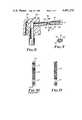
- FIG. 1is an elevational view of a portion of an aerosol container equipped with a sprayhead assembly according to the present invention
- FIG. 2is an elevational view, partially in section, of the sprayhead assembly of FIG. 1;
- FIG. 3is an end view of an outlet tube portion of the sprayhead of FIG. 1;
- FIG. 4is a fragmentary sectional view taken generally along the line 4--4 of FIG. 2;
- FIG. 5is an elevational view, partially in section, of a second embodiment of a sprayhead assembly according to the present invention.
- FIG. 6is an elevational view, partially in section, of a third embodiment of a sprayhead assembly according to the present invention which illustrates an orifice plate in solid lines and additional orifice plates in phantom lines;
- FIG. 7is a sectional view taken generally along the line 7--7 of FIG. 6;
- FIG. 8is an elevational view, partially in section, of a fourth embodiment of a sprayhead assembly according to the present invention.
- FIG. 9is a sectional view taken generally along the line 9--9 of FIG. 8;
- FIG. 10is an illustration of a spray pattern produced by a sprayhead assembly of the prior art.
- FIG. 11is an illustration of a spray pattern produced by a sprayhead assembly utilizing an embodiment of the present invention.
- FIG. 1there is shown a conventional aerosol container 1, such as is commercially available from the American Can Company, which includes a neck portion 3 in which is mounted a valve 5 which may be one of many types well known in the art, such as those available from Newman-Green Incorporated.
- the valve 5includes a dip tube (not shown) which extends to the bottom of the container 1 in order that the entire contents of the container 1 may be used.
- a sprayhead assembly 7 embodying the present inventionis inserted into the container valve 5 and includes a sprayhead 9 and a nozzle outlet tube 11 having interconnected through-passageways terminating in an elongate nozzle opening 13 through which the contents of the container 1 may flow to form a spray 15.
- the sprayhead 9, best seen in FIG. 2,includes an inlet stem 17 and a transversely oriented outlet bore 19.
- the inlet stem 17has a cylindrical wall 21 which is cut in its lower region to form a metering slot 23.
- the inlet stem 17serves to actuate the container valve 5 when the sprayhead 9 is depressed, and the metering slot 23 regulates the flow of the container 1 contents into the sprayhead 9.
- the contents of the container 1flow through the metering slot 23 into a cylindrical inlet passgeway 25 formed by the cylindrical wall 21 and the body 27 of the sprayhead 9.
- the passageway 25terminates in a cylindrical chamber 29 which is intersected by and communicates with the outlet bore 19.
- the inlet stemmay be incorporated into the container valve and the sprayhead provided with a female inlet. Either construction may be used in conjunction with the present invention.
- the sprayhead 9may be either machined or molded from any suitable material including metal or plastic, but preferably is molded in plastic due to cost considerations and the ability of plastic to resist chemical attack.
- FIGS. 1-4illustrate the preferred embodiment of the invention in which a restriction 41 having an orifice 43 is incorporated between the cylindrical chamber 29 and the outlet bore 19.
- the restriction 41is preferably molded as an integral part of the sprayhead body 27, but may be adhesively bonded or welded in place.
- the restriction 41is formed as an annular ring defining the central orifice 43 which has a cross-sectional area less than either the inner cross-sectional area of the outlet tube 11 or the cross-sectional area of the inlet passageway 25 and which is approximately equal to the cross-sectional area of the nozzle opening 13.
- the nozzle outlet tube 11includes a cylindrical body portion 45 press fitted into the outlet bore 19 to contact the restriction 41 and a flattened tip portion 47 in which the nozzle opening 13 is formed.
- the nozzle opening 13is formed by the intersection of a cylindrical outlet passageway 49 extending centrally through the outlet tube 11 and a transverse tapered groove 51.
- the preferred diametrical dimension of the orifice 43has been empirically determined to be 0.040 inches (1.0 mm) when used in conjunction with an outlet passageway 49 having a diameter of 0.059 inches (1.5 mm).
- the preferred length of the outlet passageway 49is approximately 0.580 inches (14.7 mm).
- the outlet passageway 49terminates in a conical taper 53 having an included angle of approximately 90°, and the nozzle opening 13 is formed by transversely intersecting the outlet passageway taper 53 with the tapered groove 51 having sides 55 and 57 disposed at an included angle of approximately 90°.
- the groove 51intersects the outlet passageway taper 53 to a depth substantially equal to the length of the taper 53.
- the elongate opening 13thus formed, and best seen in FIG. 3, has a substantially longer dimension along the groove 51 than transverse to the groove 51.
- nozzle opening 13 and the sprayhead tip 47 shape illustrated in FIGS. 2-4are believed to produce the most desirable fan spray pattern, many other nozzle openings and tip shapes may be useful. These alternatives are illustrated and explained in depth in U.S. application Ser. No. 282,243.
- FIG. 5illustrates a second embodiment of a sprayhead assembly 58 according to the present invention which includes a sprayhead 9a identical to the sprayhead 9 illustrated in FIG. 2 and an outlet tube 59 which has an outlet chamber 61 which extends from the end 62 of the outlet tube 59 contacting the restriction 41 to an outlet passageway 63 which communicates between the outlet chamber 61 and a nozzle opening 65 which is of the same size and shape as the nozzle opening 13.
- FIG. 6illustrates yet another embodiment of a sprayhead assembly 67 according to the present invention which also improves the uniformity of the fan spray pattern and better accommodates milling variations of the rubber and variations in the solids content of the adhesive solution.
- a sprayhead 69is included which is generally the same as the sprayheads 9 and 9a described above, except that the sprayhead 69 has an annular shoulder 71 in place of the restriction 41, which serves merely to limit the travel of an outlet tube 73 as it is inserted into the sprayhead 69.
- the outlet tube 73includes an outlet chamber 75, an outlet passageway 77 and a nozzle opening 79 which are identical in all respects to the outlet chamber 61, outlet passageway 63 and nozzle opening 65 of the sprayhead assembly 58 of FIG.
- the length of the outlet tube 73is increased to accommodate an outlet chamber 75 0.870 inches (22.1 mm) in length.
- a restriction 91formed as an annular plate which includes an orifice 93 coaxial with the outlet passageway 77 and the nozzle opening 79.
- the plate 91is preferably made of plastic, as is the outlet tube 73, and is secured within the outlet chamber 75 either by press fitting, adhesive bonding or welding. Suitable dimensions for the plate 91 and the orifice 93 have been found to be 0.040 inches (1 mm) in width and 0.050 inches (1.25 mm) in diameter, respectively.
- spray pattern uniformitymay be enhanced by providing more than one plate 91 within the outlet chamber 75.
- a plurality of plates 91may be inserted into the outlet chamber 75 and spaced equally from each other and the ends of the outlet chamber 75.
- two plates 91produce acceptable results and it is contemplated that more than three plates 91 could be employed if located symmetrically within the chamber 75 and spaced equally from each other and the ends of the outlet chamber 75.
- FIGS. 8 and 9show a sprayhead assembly 95 including an outlet tube 97 which has a length so as to provide an outlet chamber 99 having a diameter of 0.076 inches (1.9 mm) and a length of 0.870 inches (22.1 mm).
- the tube 97is crimped or molded to form a rectangular orifice 101 the longitudinal center of which is located 0.440 inches (11 mm) from the end of the outlet tube 97 inserted in a sprayhead 103.
- the orifice 101is approximately 0.080 inches (2 mm) in length, and as best seen in FIG. 9, is rectangular with rounded ends in cross-section and has a dimension between flat surfaces 105 and 107 of 0.030 inches (0.75 mm).
- FIG. 8has been shown to produce an acceptable fan spray pattern and may additionally provide the advantage of reduced cost.
- FIG. 10 and 11illustrate the efficacy of providing an orifice 43, 93 or 101 located within the sprayhead assembly 7, 58, 67 or 95 between the container 1 and the nozzle opening 13, 65, 79 or 111.
- FIG. 10illustrates a portion of a fan spray pattern 113 produced by a prior art sprayhead assembly of U.S. application Ser. No. 282,243, as it would appear when sprayed from above onto a horizontal surface from a container 1 held at approximately 45° with the nozzle opening approximately 6 inches (150 mm) from the surface.
- the spray pattern 113is distinguished by sharply defined and stringy margins or "tails" 115 on both ends, and areas of light coverage 117 toward the ends of the pattern 113. Also, the amount of material sprayed is found to be much heavier toward the top of the pattern 113 than toward the bottom.
- FIG. 11illustrates a fan spray pattern 119 produced under the same conditions by a sprayhead assembly 7, 58, 67 or 95 including any of the orifices 43, 93 or 101 illustrated by FIGS. 2, 5, 6 or 8.
- the spray pattern 119 of FIG. 11is distinguished from the spray pattern 113 of FIG. 10 by the absence of tails 115 and much less severe areas of light coverage 117. There is generally found to be one area of light coverage 121 located in the bottom half of the spray pattern 119, but this area 121 is found to contain more sprayed material than the areas of light coverage 117 in the spray pattern 113 of FIG. 10.
- the spray pattern 119 produced when an orifice 43, 93 or 101 is usedhas been found to be more uniform end-to-end than the spray pattern 113 produced by a sprayhead assembly not containing an orifice 43, 93 or 101.
- This formulationwas placed in a Model 202 ⁇ 406 aerosol container 1, commercially available from the American Can Company, and capped with a Model R10-123 can valve 5 available from Newman-Green Incorporated.
- the container 1was filld with 0.85 ounces (24 g) of dimethyl ether through the valve 5, thereby providing an 11.1 percent aerosol solids level in the container 1.
- the pressue inside the aerosol container 1reached approximately 25 psi (0.17 megapascals).
- a perfect spray patternwould result in each one-fifth of the spray pattern containing exactly 20 percent of the total amount of material sprayed. While none of the sprayhead assemblies 7, 58, 67 and 95 reached this level of perfection, the examples show that a sprayhead assembly 7, 58, 67 or 95 containing any one of the embodiments of the orifice 43, 93 or 101 described above produced a more uniform fan spray pattern than did the sprayhead assembly of the prior art which contained no orifice.
Landscapes
- Chemical & Material Sciences (AREA)
- Dispersion Chemistry (AREA)
- Engineering & Computer Science (AREA)
- Mechanical Engineering (AREA)
- Containers And Packaging Bodies Having A Special Means To Remove Contents (AREA)
Abstract
Description
TABLE I ______________________________________ Weight, Ingredient ounces (grams) ______________________________________ 60 to 80 Mooney viscosity 0.24 (6.8) polychloroprene copolymer.sup.1 t-Butyl phenolic resin.sup.2 0.12 (3.4) Magnesium oxide.sup.3 0.05 (1.4) Water 0.0025 (0.07) Methylene chloride 2.4 (68.4) ______________________________________ .sup.1 "Neoprene AC", commercially available from E. I. du Pont de Nemour Co., milled 5 minutes on a tworoll mill. .sup.2 "CKR 1634", commercially available from Union Carbide Co. .sup.3 "Maglite A", commercially available from Merck Chemical Co.
TABLE II ______________________________________ Material in One-Fifth Sprayhead of Spray Pattern Width Ex. Assembly (% of total) No. (FIG. No.) Away from Container → Toward Container ______________________________________ 1 2 18.3 11.9 23.9 22.0 23.9 2 5 22.6 23.8 23.8 10.7 19.0 3 6 23.8 22.6 25.0 10.7 17.9 (one orifice) 4 6 19.1 12.4 20.2 18.0 30.3 (two orifices) 5 6 11.0 11.0 15.1 39.7 23.3 (three orifices) 6 8 25.8 16.5 18.6 13.4 25.8 7 Prior Art 34.3 32.4 12.7 7.8 12.5 ______________________________________
Claims (14)
Priority Applications (10)
| Application Number | Priority Date | Filing Date | Title |
|---|---|---|---|
| US06/378,789US4401272A (en) | 1982-05-17 | 1982-05-17 | Aerosol fan sprayhead |
| DE8282902419TDE3275532D1 (en) | 1981-07-10 | 1982-07-01 | AEROSOL FAN SPRAYHEAD |
| AU87610/82AAU558064B2 (en) | 1981-07-10 | 1982-07-01 | Aerosol fan sprayhead |
| JP57502382AJPS58501068A (en) | 1981-07-10 | 1982-07-01 | aerosol container |
| BR8207783ABR8207783A (en) | 1981-07-10 | 1982-07-01 | AEROSOL FAN TYPE ATOMIZATION HEAD |
| PCT/US1982/000890WO1983000134A1 (en) | 1981-07-10 | 1982-07-01 | Aerosol fan sprayhead |
| EP82902419AEP0083634B1 (en) | 1981-07-10 | 1982-07-01 | Aerosol fan sprayhead |
| MX193524AMX157321A (en) | 1981-07-10 | 1982-07-09 | IMPROVEMENTS IN AEROSOL CONTAINER FOR SOLUBLE ELASTOMERIC ADHESIVE POLYMERIC SOLUTIONS |
| IT48791/82AIT1148200B (en) | 1981-07-10 | 1982-07-09 | AEROSOL DISPENSER CONTAINER WITH FAN SPRAY HEAD |
| CA000421324ACA1183817A (en) | 1982-05-17 | 1983-02-10 | Aerosol fan sprayhead |
Applications Claiming Priority (1)
| Application Number | Priority Date | Filing Date | Title |
|---|---|---|---|
| US06/378,789US4401272A (en) | 1982-05-17 | 1982-05-17 | Aerosol fan sprayhead |
Publications (1)
| Publication Number | Publication Date |
|---|---|
| US4401272Atrue US4401272A (en) | 1983-08-30 |
Family
ID=23494564
Family Applications (1)
| Application Number | Title | Priority Date | Filing Date |
|---|---|---|---|
| US06/378,789Expired - LifetimeUS4401272A (en) | 1981-07-10 | 1982-05-17 | Aerosol fan sprayhead |
Country Status (2)
| Country | Link |
|---|---|
| US (1) | US4401272A (en) |
| CA (1) | CA1183817A (en) |
Cited By (54)
| Publication number | Priority date | Publication date | Assignee | Title |
|---|---|---|---|---|
| US4541551A (en)* | 1978-01-13 | 1985-09-17 | Henkel Kommanditgesellschaft Auf Aktien | Sealing top for containers for powdered or granular materials |
| US4640441A (en)* | 1984-05-14 | 1987-02-03 | Lever Brothers Company | Liquid-dispensing container |
| US4697611A (en)* | 1986-03-19 | 1987-10-06 | Worthington Cylinder Corporation | Device and method for restricting gas flow |
| US4754897A (en)* | 1986-02-11 | 1988-07-05 | Bespak Plc | Gas pressurized dispensing containers |
| US4884750A (en)* | 1985-07-23 | 1989-12-05 | Winfried Werding | Thrust regulator comprising a mounting enclosure |
| US4991750A (en)* | 1988-12-08 | 1991-02-12 | Pittway Corp. | Mounting for extension tube |
| US5125546A (en)* | 1988-11-22 | 1992-06-30 | Dmw (Technology) Limited | Flow discharge valve |
| US5310095A (en)* | 1992-02-24 | 1994-05-10 | Djs&T Limited Partnership | Spray texturing apparatus and method having a plurality of dispersing tubes |
| US5322191A (en)* | 1990-09-06 | 1994-06-21 | Johnson Lonnie G | Low pressure, high volume pressurized water gun |
| US5423458A (en)* | 1994-04-28 | 1995-06-13 | Micro Care Corporation | Electrostatic-safe aerosol dispenser |
| US5639025A (en)* | 1995-07-07 | 1997-06-17 | The Procter & Gamble Company | High Viscosity pump sprayer utilizing fan spray nozzle |
| US5642860A (en)* | 1995-07-07 | 1997-07-01 | The Procter & Gamble Company | Pump sprayer for viscous or solids laden liquids |
| US5655691A (en)* | 1992-02-24 | 1997-08-12 | Homax Products, Inc. | Spray texturing device |
| US5711484A (en)* | 1993-09-14 | 1998-01-27 | Minnesota Mining And Manufacturing Company | Dispensing tube for directing the dispensing of fluids |
| US5934518A (en)* | 1992-02-24 | 1999-08-10 | Homax Products, Inc. | Aerosol texture assembly and method |
| EP1053791A1 (en)* | 1999-05-21 | 2000-11-22 | Premark RWP Holdings, Inc. | Spray can nozzle for spraying viscous substances |
| US6152335A (en)* | 1993-03-12 | 2000-11-28 | Homax Products, Inc. | Aerosol spray texture apparatus for a particulate containing material |
| US6290109B1 (en)* | 1998-01-07 | 2001-09-18 | Rexam Sofab | Dispensing head for liquid product container |
| EP1160179A1 (en) | 2000-05-31 | 2001-12-05 | Premark RWP Holdings, Inc. | Very high solid content aerosol delivery system |
| US6432084B1 (en)* | 1999-05-07 | 2002-08-13 | Baxter International Inc. | Non-newtonian fluid spray applicator and method |
| US20030150887A1 (en)* | 2002-02-12 | 2003-08-14 | Rodney Laible | Closed loop dispensing system |
| US6616019B2 (en)* | 2001-07-18 | 2003-09-09 | Closure Medical Corporation | Adhesive applicator with improved applicator tip |
| US6635703B1 (en) | 1998-07-30 | 2003-10-21 | Premark Rwp Holdings, Inc. | Very high solids adhesive |
| US20040089676A1 (en)* | 2002-11-12 | 2004-05-13 | Lester Greer | Storage systems and methods for aerosol accessories |
| US20040108331A1 (en)* | 2002-12-06 | 2004-06-10 | Smith Jeremy P. | Actuator with stabilizing ribs and improved fan spray insert |
| US20040134941A1 (en)* | 2002-02-12 | 2004-07-15 | Rodney Laible | Dosing and/or dispensing system |
| US20040164104A1 (en)* | 2002-02-12 | 2004-08-26 | Rodney Laible | Dosing and/or dispensing system |
| US20040206786A1 (en)* | 2002-02-12 | 2004-10-21 | Rodney Laible | Dosing and/or dispensing system |
| US6884230B1 (en) | 1998-03-09 | 2005-04-26 | Baxter International Inc. | Dispensing head for a tissue sealant applicator and process of use |
| US6921380B1 (en) | 1998-10-01 | 2005-07-26 | Baxter International Inc. | Component mixing catheter |
| US20050269356A1 (en)* | 2004-05-24 | 2005-12-08 | Colgate-Palmolive Company | Controlling flow from multi-chamber containers |
| US20060079588A1 (en)* | 2004-10-08 | 2006-04-13 | Greer Lester R Jr | Particulate materials for acoustic texture material |
| US7487893B1 (en) | 2004-10-08 | 2009-02-10 | Homax Products, Inc. | Aerosol systems and methods for dispensing texture material |
| US20100258593A1 (en)* | 2009-04-09 | 2010-10-14 | Rodney Laible | Closed loop dispensing system with mechanical venting means |
| US7845523B1 (en)* | 1992-02-24 | 2010-12-07 | Homax Products, Inc. | Systems and methods for applying texture material to ceiling surfaces |
| US8251255B1 (en) | 2004-07-02 | 2012-08-28 | Homax Products, Inc. | Aerosol spray texture apparatus for a particulate containing material |
| US8317065B2 (en) | 1992-02-24 | 2012-11-27 | Homax Products, Inc. | Actuator systems and methods for aerosol wall texturing |
| US20120305121A1 (en)* | 2011-06-03 | 2012-12-06 | Samuel Sanchez | Fiberboard tube and closure assembly |
| US8344056B1 (en) | 2007-04-04 | 2013-01-01 | Homax Products, Inc. | Aerosol dispensing systems, methods, and compositions for repairing interior structure surfaces |
| US8342421B2 (en) | 2004-01-28 | 2013-01-01 | Homax Products Inc | Texture material for covering a repaired portion of a textured surface |
| US8353465B2 (en) | 2003-04-10 | 2013-01-15 | Homax Products, Inc | Dispensers for aerosol systems |
| WO2013055323A1 (en)* | 2011-10-12 | 2013-04-18 | Aptargroup, Inc. | Fan spray structure for use in dispensing actuator |
| US8580349B1 (en) | 2007-04-05 | 2013-11-12 | Homax Products, Inc. | Pigmented spray texture material compositions, systems, and methods |
| US8701944B2 (en) | 1992-02-24 | 2014-04-22 | Homax Products, Inc. | Actuator systems and methods for aerosol wall texturing |
| US8708203B2 (en) | 2012-05-07 | 2014-04-29 | Rl Innovations, Llc | Screw-on throat plug assembly |
| US9156042B2 (en) | 2011-07-29 | 2015-10-13 | Homax Products, Inc. | Systems and methods for dispensing texture material using dual flow adjustment |
| US9156602B1 (en) | 2012-05-17 | 2015-10-13 | Homax Products, Inc. | Actuators for dispensers for texture material |
| US9248457B2 (en) | 2011-07-29 | 2016-02-02 | Homax Products, Inc. | Systems and methods for dispensing texture material using dual flow adjustment |
| US9382060B1 (en) | 2007-04-05 | 2016-07-05 | Homax Products, Inc. | Spray texture material compositions, systems, and methods with accelerated dry times |
| US9435120B2 (en) | 2013-03-13 | 2016-09-06 | Homax Products, Inc. | Acoustic ceiling popcorn texture materials, systems, and methods |
| USD787326S1 (en) | 2014-12-09 | 2017-05-23 | Ppg Architectural Finishes, Inc. | Cap with actuator |
| US9776785B2 (en) | 2013-08-19 | 2017-10-03 | Ppg Architectural Finishes, Inc. | Ceiling texture materials, systems, and methods |
| US20240067514A1 (en)* | 2022-08-25 | 2024-02-29 | Pepsico, Inc. | Beverage flavor dosing system |
| US12221269B1 (en)* | 2023-07-28 | 2025-02-11 | Robert Bruce Veduccio | Spray can buttons for pressurized spray cans |
Citations (3)
| Publication number | Priority date | Publication date | Assignee | Title |
|---|---|---|---|---|
| US2968441A (en)* | 1958-08-15 | 1961-01-17 | Doyle D Holcomb | Spray nozzle assembly for use with aerosol can |
| US3000576A (en)* | 1960-03-01 | 1961-09-19 | Spee Flo Company | Spray gun |
| US4030667A (en)* | 1974-06-05 | 1977-06-21 | Establissements Valois S.A. | Push-button having a calibrated outlet for a container under pressure |
- 1982
- 1982-05-17USUS06/378,789patent/US4401272A/ennot_activeExpired - Lifetime
- 1983
- 1983-02-10CACA000421324Apatent/CA1183817A/ennot_activeExpired
Patent Citations (3)
| Publication number | Priority date | Publication date | Assignee | Title |
|---|---|---|---|---|
| US2968441A (en)* | 1958-08-15 | 1961-01-17 | Doyle D Holcomb | Spray nozzle assembly for use with aerosol can |
| US3000576A (en)* | 1960-03-01 | 1961-09-19 | Spee Flo Company | Spray gun |
| US4030667A (en)* | 1974-06-05 | 1977-06-21 | Establissements Valois S.A. | Push-button having a calibrated outlet for a container under pressure |
Cited By (117)
| Publication number | Priority date | Publication date | Assignee | Title |
|---|---|---|---|---|
| US4541551A (en)* | 1978-01-13 | 1985-09-17 | Henkel Kommanditgesellschaft Auf Aktien | Sealing top for containers for powdered or granular materials |
| US4640441A (en)* | 1984-05-14 | 1987-02-03 | Lever Brothers Company | Liquid-dispensing container |
| US4884750A (en)* | 1985-07-23 | 1989-12-05 | Winfried Werding | Thrust regulator comprising a mounting enclosure |
| US4754897A (en)* | 1986-02-11 | 1988-07-05 | Bespak Plc | Gas pressurized dispensing containers |
| US4697611A (en)* | 1986-03-19 | 1987-10-06 | Worthington Cylinder Corporation | Device and method for restricting gas flow |
| US5125546A (en)* | 1988-11-22 | 1992-06-30 | Dmw (Technology) Limited | Flow discharge valve |
| US4991750A (en)* | 1988-12-08 | 1991-02-12 | Pittway Corp. | Mounting for extension tube |
| US5322191A (en)* | 1990-09-06 | 1994-06-21 | Johnson Lonnie G | Low pressure, high volume pressurized water gun |
| US5934518A (en)* | 1992-02-24 | 1999-08-10 | Homax Products, Inc. | Aerosol texture assembly and method |
| US8573451B2 (en) | 1992-02-24 | 2013-11-05 | Homax Products, Inc. | Actuator systems and methods for aerosol wall texturing |
| US5489048A (en)* | 1992-02-24 | 1996-02-06 | Djs&T Limited Partnership | Spray texturing apparatus and method |
| US9181020B2 (en) | 1992-02-24 | 2015-11-10 | Homax Products, Inc. | Actuator systems and methods for aerosol wall texturing |
| US5310095A (en)* | 1992-02-24 | 1994-05-10 | Djs&T Limited Partnership | Spray texturing apparatus and method having a plurality of dispersing tubes |
| US5645198A (en)* | 1992-02-24 | 1997-07-08 | Homax Products, Inc. | Spray texturing apparatus and method |
| US5655691A (en)* | 1992-02-24 | 1997-08-12 | Homax Products, Inc. | Spray texturing device |
| US9079703B2 (en) | 1992-02-24 | 2015-07-14 | Homax Products, Inc. | Actuator systems and methods for aerosol wall texturing |
| US20110132935A1 (en)* | 1992-02-24 | 2011-06-09 | Homax Products, Inc. | Systems and Methods for Applying Texture Material to Ceiling Surfaces |
| US9845185B2 (en) | 1992-02-24 | 2017-12-19 | Ppg Architectural Finishes, Inc. | Systems and methods for applying texture material |
| US7845523B1 (en)* | 1992-02-24 | 2010-12-07 | Homax Products, Inc. | Systems and methods for applying texture material to ceiling surfaces |
| US8505786B2 (en) | 1992-02-24 | 2013-08-13 | Homax Products, Inc. | Actuator systems and methods for aerosol wall texturing |
| US8584898B2 (en) | 1992-02-24 | 2013-11-19 | Homax Products, Inc. | Systems and methods for applying texture material to ceiling surfaces |
| US8317065B2 (en) | 1992-02-24 | 2012-11-27 | Homax Products, Inc. | Actuator systems and methods for aerosol wall texturing |
| US8985392B2 (en) | 1992-02-24 | 2015-03-24 | Homax Products, Inc. | Systems and methods for applying texture material to ceiling surfaces |
| US8313011B2 (en) | 1992-02-24 | 2012-11-20 | Homax Products, Inc. | Systems and methods for applying texture material to ceiling surfaces |
| US8701944B2 (en) | 1992-02-24 | 2014-04-22 | Homax Products, Inc. | Actuator systems and methods for aerosol wall texturing |
| US8887953B2 (en) | 1992-02-24 | 2014-11-18 | Homax Products, Inc. | Systems and methods for applying texture material to ceiling surfaces |
| US6152335A (en)* | 1993-03-12 | 2000-11-28 | Homax Products, Inc. | Aerosol spray texture apparatus for a particulate containing material |
| US8844765B2 (en) | 1993-03-12 | 2014-09-30 | Homax Products, Inc. | Aerosol spray texture apparatus for a particulate containing material |
| US6641005B1 (en) | 1993-03-12 | 2003-11-04 | Homax Products, Inc. | Aerosol spray texture apparatus for a particulate containing material |
| US8157135B2 (en) | 1993-03-12 | 2012-04-17 | Homax Products, Inc. | Aerosol spray texture apparatus for a particulate containing material |
| US6352184B1 (en) | 1993-03-12 | 2002-03-05 | Homax Products, Inc. | Aerosol spray texture apparatus for a particulate containing material |
| US7014073B1 (en) | 1993-03-12 | 2006-03-21 | Homax Products, Inc. | Aerosol spray texture apparatus for a particulate containing material |
| US20090188948A1 (en)* | 1993-03-12 | 2009-07-30 | Homax Products, Inc. | Aerosol Spray Texture Apparatus For A Particulate Containing Material |
| US7481338B1 (en) | 1993-03-12 | 2009-01-27 | Homax Products, Inc.. | Aerosol spray texture apparatus for a particulate containing material |
| US5711484A (en)* | 1993-09-14 | 1998-01-27 | Minnesota Mining And Manufacturing Company | Dispensing tube for directing the dispensing of fluids |
| US5423458A (en)* | 1994-04-28 | 1995-06-13 | Micro Care Corporation | Electrostatic-safe aerosol dispenser |
| US5642860A (en)* | 1995-07-07 | 1997-07-01 | The Procter & Gamble Company | Pump sprayer for viscous or solids laden liquids |
| US5639025A (en)* | 1995-07-07 | 1997-06-17 | The Procter & Gamble Company | High Viscosity pump sprayer utilizing fan spray nozzle |
| US6290109B1 (en)* | 1998-01-07 | 2001-09-18 | Rexam Sofab | Dispensing head for liquid product container |
| US6884230B1 (en) | 1998-03-09 | 2005-04-26 | Baxter International Inc. | Dispensing head for a tissue sealant applicator and process of use |
| US6345775B1 (en)* | 1998-07-30 | 2002-02-12 | Wilsoart International, Inc. | Very high solid content aerosol delivery system |
| US6635703B1 (en) | 1998-07-30 | 2003-10-21 | Premark Rwp Holdings, Inc. | Very high solids adhesive |
| US6921380B1 (en) | 1998-10-01 | 2005-07-26 | Baxter International Inc. | Component mixing catheter |
| US6432084B1 (en)* | 1999-05-07 | 2002-08-13 | Baxter International Inc. | Non-newtonian fluid spray applicator and method |
| US6896205B2 (en)* | 1999-05-21 | 2005-05-24 | Premark Rwp Holdings, Inc. | Very high solid content aerosol delivery system |
| EP1053791A1 (en)* | 1999-05-21 | 2000-11-22 | Premark RWP Holdings, Inc. | Spray can nozzle for spraying viscous substances |
| US6433051B1 (en) | 1999-05-21 | 2002-08-13 | Wilsonart International | Very high solid content aerosol delivery system |
| EP1160179A1 (en) | 2000-05-31 | 2001-12-05 | Premark RWP Holdings, Inc. | Very high solid content aerosol delivery system |
| US6616019B2 (en)* | 2001-07-18 | 2003-09-09 | Closure Medical Corporation | Adhesive applicator with improved applicator tip |
| US20030150887A1 (en)* | 2002-02-12 | 2003-08-14 | Rodney Laible | Closed loop dispensing system |
| US20040134941A1 (en)* | 2002-02-12 | 2004-07-15 | Rodney Laible | Dosing and/or dispensing system |
| US6968983B2 (en) | 2002-02-12 | 2005-11-29 | Rodney Laible | Closed loop dispensing system |
| US6923345B1 (en) | 2002-02-12 | 2005-08-02 | Rodney Laible | Dispensing system |
| US6945432B2 (en) | 2002-02-12 | 2005-09-20 | Rodney Laible | Dosing and/or dispensing system |
| US20040164104A1 (en)* | 2002-02-12 | 2004-08-26 | Rodney Laible | Dosing and/or dispensing system |
| US6945433B2 (en) | 2002-02-12 | 2005-09-20 | Rodney Laible | Dosing and/or dispensing system |
| US6986443B2 (en) | 2002-02-12 | 2006-01-17 | Rodney Laible | Dosing and/or dispensing system |
| US20040206786A1 (en)* | 2002-02-12 | 2004-10-21 | Rodney Laible | Dosing and/or dispensing system |
| US7232047B2 (en) | 2002-11-12 | 2007-06-19 | Homax Products, Inc. | Storage systems and methods for aerosol accessories |
| US20070290011A1 (en)* | 2002-11-12 | 2007-12-20 | Greer Lester R Jr | Storage systems and methods for aerosol accessories for dispensing texture material |
| US20050258198A1 (en)* | 2002-11-12 | 2005-11-24 | Greer Lester R Jr | Storage systems and methods for aerosol accessories |
| US20040089676A1 (en)* | 2002-11-12 | 2004-05-13 | Lester Greer | Storage systems and methods for aerosol accessories |
| US6910608B2 (en) | 2002-11-12 | 2005-06-28 | Homax Products, Inc. | Storage systems and methods for aerosol accessories |
| US20040108331A1 (en)* | 2002-12-06 | 2004-06-10 | Smith Jeremy P. | Actuator with stabilizing ribs and improved fan spray insert |
| US7143959B2 (en)* | 2002-12-06 | 2006-12-05 | Summit Packaging Systems, Inc. | Actuator with stabilizing ribs and improved fan spray insert |
| US8353465B2 (en) | 2003-04-10 | 2013-01-15 | Homax Products, Inc | Dispensers for aerosol systems |
| US8820656B2 (en) | 2003-04-10 | 2014-09-02 | Homax Products, Inc. | Dispenser for aerosol systems |
| US9132953B2 (en) | 2003-04-10 | 2015-09-15 | Homax Products, Inc. | Dispenser for aerosol systems |
| US9248951B2 (en) | 2004-01-28 | 2016-02-02 | Homax Products, Inc. | Texture material for covering a repaired portion of a textured surface |
| US8342421B2 (en) | 2004-01-28 | 2013-01-01 | Homax Products Inc | Texture material for covering a repaired portion of a textured surface |
| US9187236B2 (en) | 2004-01-28 | 2015-11-17 | Homax Products, Inc. | Aerosol system for repairing a patched portion of a surface |
| US7617950B2 (en)* | 2004-05-24 | 2009-11-17 | Colgate-Palmolive Company | Controlling flow from multi-chamber containers |
| US20050269356A1 (en)* | 2004-05-24 | 2005-12-08 | Colgate-Palmolive Company | Controlling flow from multi-chamber containers |
| US8561840B2 (en) | 2004-07-02 | 2013-10-22 | Homax Products, Inc. | Aerosol spray texture apparatus for a particulate containing material |
| US8251255B1 (en) | 2004-07-02 | 2012-08-28 | Homax Products, Inc. | Aerosol spray texture apparatus for a particulate containing material |
| US9004316B2 (en) | 2004-07-02 | 2015-04-14 | Homax Products, Inc. | Aerosol spray texture apparatus for a particulate containing material |
| US7784649B2 (en) | 2004-10-08 | 2010-08-31 | Homax Products, Inc. | Aerosol systems and methods for dispensing texture material |
| US20090255961A1 (en)* | 2004-10-08 | 2009-10-15 | Homax Products, Inc. | Aerosol systems and methods for dispensing texture material |
| US8420705B2 (en) | 2004-10-08 | 2013-04-16 | Homax Products, Inc. | Particulate materials for acoustic texture material |
| US7374068B2 (en) | 2004-10-08 | 2008-05-20 | Homax Products, Inc. | Particulate materials for acoustic texture material |
| US20080128203A1 (en)* | 2004-10-08 | 2008-06-05 | Greer Lester R | Particulate materials for acoustic texture material |
| US8336742B2 (en) | 2004-10-08 | 2012-12-25 | Homax Products, Inc. | Aerosol systems and methods for dispensing texture material |
| US7487893B1 (en) | 2004-10-08 | 2009-02-10 | Homax Products, Inc. | Aerosol systems and methods for dispensing texture material |
| US7947753B2 (en) | 2004-10-08 | 2011-05-24 | Homax Products, Inc. | Particulate materials for acoustic texture material |
| US8622255B2 (en) | 2004-10-08 | 2014-01-07 | Homax Products, Inc. | Aerosol systems and methods for dispensing texture material |
| US8172113B2 (en) | 2004-10-08 | 2012-05-08 | Homax Products, Inc. | Aerosol systems and methods for dispensing texture material |
| US20060079588A1 (en)* | 2004-10-08 | 2006-04-13 | Greer Lester R Jr | Particulate materials for acoustic texture material |
| US20110036872A1 (en)* | 2004-10-08 | 2011-02-17 | Homax Products, Inc. | Aerosol systems and methods for dispensing texture material |
| US9004323B2 (en) | 2004-10-08 | 2015-04-14 | Homax Products, Inc. | Aerosol systems and methods for dispensing texture material |
| US20110049179A1 (en)* | 2004-10-08 | 2011-03-03 | Homax Products, Inc. | Aerosol systems and methods for dispensing texture material |
| US8042713B2 (en) | 2004-10-08 | 2011-10-25 | Homax Products, Inc. | Aerosol systems and methods for dispensing texture material |
| US8883902B2 (en) | 2007-04-04 | 2014-11-11 | Homax Products, Inc. | Aerosol dispensing systems and methods and compositions for repairing interior structure surfaces |
| US9580233B2 (en) | 2007-04-04 | 2017-02-28 | Ppg Architectural Finishes, Inc. | Spray texture material compositions, systems, and methods with anti-corrosion characteristics |
| US8551572B1 (en) | 2007-04-04 | 2013-10-08 | Homax Products, Inc. | Spray texture material compositions, systems, and methods with anti-corrosion characteristics |
| US8784942B2 (en) | 2007-04-04 | 2014-07-22 | Homax Products, Inc. | Spray texture material compositions, systems, and methods with anti-corrosion characteristics |
| US9415927B2 (en) | 2007-04-04 | 2016-08-16 | Homax Products, Inc. | Spray texture material compositions, systems, and methods with anti-corrosion characteristics |
| US8344056B1 (en) | 2007-04-04 | 2013-01-01 | Homax Products, Inc. | Aerosol dispensing systems, methods, and compositions for repairing interior structure surfaces |
| US9592527B2 (en) | 2007-04-05 | 2017-03-14 | Ppg Architectural Finishes, Inc. | Spray texture material compositions, systems, and methods with accelerated dry times |
| US8580349B1 (en) | 2007-04-05 | 2013-11-12 | Homax Products, Inc. | Pigmented spray texture material compositions, systems, and methods |
| US9382060B1 (en) | 2007-04-05 | 2016-07-05 | Homax Products, Inc. | Spray texture material compositions, systems, and methods with accelerated dry times |
| US20100258593A1 (en)* | 2009-04-09 | 2010-10-14 | Rodney Laible | Closed loop dispensing system with mechanical venting means |
| US8083107B2 (en) | 2009-04-09 | 2011-12-27 | Rodney Laible | Closed loop dispensing system with mechanical venting means |
| US20120305121A1 (en)* | 2011-06-03 | 2012-12-06 | Samuel Sanchez | Fiberboard tube and closure assembly |
| US9156042B2 (en) | 2011-07-29 | 2015-10-13 | Homax Products, Inc. | Systems and methods for dispensing texture material using dual flow adjustment |
| US9248457B2 (en) | 2011-07-29 | 2016-02-02 | Homax Products, Inc. | Systems and methods for dispensing texture material using dual flow adjustment |
| CN103842033A (en)* | 2011-10-12 | 2014-06-04 | 万通集团公司 | Fan spray structure for use in dispensing actuator |
| RU2571039C1 (en)* | 2011-10-12 | 2015-12-20 | Аптаргруп, Инк. | Structure to create spray fan, and intended for use in issuing starter |
| WO2013055323A1 (en)* | 2011-10-12 | 2013-04-18 | Aptargroup, Inc. | Fan spray structure for use in dispensing actuator |
| CN103842033B (en)* | 2011-10-12 | 2018-07-17 | 万通集团公司 | Fan-spray structure for being used in sending actuator |
| US10112767B2 (en) | 2011-10-12 | 2018-10-30 | Aptargroup, Inc. | Fan spray structure for use in dispensing actuator |
| US8708203B2 (en) | 2012-05-07 | 2014-04-29 | Rl Innovations, Llc | Screw-on throat plug assembly |
| US9156602B1 (en) | 2012-05-17 | 2015-10-13 | Homax Products, Inc. | Actuators for dispensers for texture material |
| US9435120B2 (en) | 2013-03-13 | 2016-09-06 | Homax Products, Inc. | Acoustic ceiling popcorn texture materials, systems, and methods |
| US9776785B2 (en) | 2013-08-19 | 2017-10-03 | Ppg Architectural Finishes, Inc. | Ceiling texture materials, systems, and methods |
| USD787326S1 (en) | 2014-12-09 | 2017-05-23 | Ppg Architectural Finishes, Inc. | Cap with actuator |
| US20240067514A1 (en)* | 2022-08-25 | 2024-02-29 | Pepsico, Inc. | Beverage flavor dosing system |
| US12221269B1 (en)* | 2023-07-28 | 2025-02-11 | Robert Bruce Veduccio | Spray can buttons for pressurized spray cans |
Also Published As
| Publication number | Publication date |
|---|---|
| CA1183817A (en) | 1985-03-12 |
Similar Documents
| Publication | Publication Date | Title |
|---|---|---|
| US4401272A (en) | Aerosol fan sprayhead | |
| CA1149346A (en) | Foam dispenser | |
| US4247048A (en) | Dispensing nozzle | |
| US4846376A (en) | Inversion foamer | |
| AU2002238562B2 (en) | Foamer | |
| EP0557714B1 (en) | Atomizer bottle with pump operable by squeezing | |
| US5890661A (en) | Colliding stream spray dispensing system with a moldable nozzle | |
| AU558064B2 (en) | Aerosol fan sprayhead | |
| MXPA01009561A (en) | Dual dispense container having cloverleaf orifice. | |
| CN1096304C (en) | Fan spray nozzles having elastomeric dome-shaped tips | |
| CA2194453A1 (en) | Applicator for shear thinning viscous coating materials | |
| KR950700127A (en) | CONSUMER PRODUCT PACKAGE INCORPORATIMG A SPRAY DEVICE UTILIZING LARGE DIAMETER BUBBLES | |
| EP1053791B1 (en) | Spray can nozzle for spraying viscous substances | |
| EP1160179A1 (en) | Very high solid content aerosol delivery system | |
| US3140052A (en) | Spray nozzle comprising a base member and a cap | |
| US4353876A (en) | Apparatus for mixing chemical products under running water | |
| US5779156A (en) | Spray dispenser and system for spraying viscous liquids | |
| US3986673A (en) | Nozzle assemblies for atomizing and mixing different fluids and combining the mixture with solids and the like | |
| US5082372A (en) | Fluid mixing device | |
| JPH05246475A (en) | Nozzle of aerosol device | |
| GB2244013A (en) | An actuator for a dispensing container | |
| JPH029912Y2 (en) | ||
| AU7173700A (en) | Very high solid content aerosol delivery system | |
| JPS5871967A (en) | Partition wall type aerosol coating material | |
| Weber et al. | Thermoplastic primer mixture |
Legal Events
| Date | Code | Title | Description |
|---|---|---|---|
| AS | Assignment | Owner name:MINNESOTA MINING AND MANUFACTURING COMPANY, ST. PA Free format text:ASSIGNMENT OF ASSIGNORS INTEREST.;ASSIGNORS:MERTON, WILFRED R.;PIETERICK, JEROME A.;REEL/FRAME:004002/0472 Effective date:19820514 Owner name:MINNESOTA MINING AND MANUFACTURING COMPANY, ST. PA Free format text:ASSIGNMENT OF ASSIGNORS INTEREST;ASSIGNORS:MERTON, WILFRED R.;PIETERICK, JEROME A.;REEL/FRAME:004002/0472 Effective date:19820514 | |
| STCF | Information on status: patent grant | Free format text:PATENTED CASE | |
| MAFP | Maintenance fee payment | Free format text:PAYMENT OF MAINTENANCE FEE, 4TH YEAR, PL 96-517 (ORIGINAL EVENT CODE: M170); ENTITY STATUS OF PATENT OWNER: LARGE ENTITY Year of fee payment:4 | |
| MAFP | Maintenance fee payment | Free format text:PAYMENT OF MAINTENANCE FEE, 8TH YEAR, PL 96-517 (ORIGINAL EVENT CODE: M171); ENTITY STATUS OF PATENT OWNER: LARGE ENTITY Year of fee payment:8 | |
| MAFP | Maintenance fee payment | Free format text:PAYMENT OF MAINTENANCE FEE, 12TH YEAR, LARGE ENTITY (ORIGINAL EVENT CODE: M185); ENTITY STATUS OF PATENT OWNER: LARGE ENTITY Year of fee payment:12 |