US4401262A - Energy saving thermostat with means to shift offset time program - Google Patents
Energy saving thermostat with means to shift offset time programDownload PDFInfo
- Publication number
- US4401262A US4401262AUS06/389,538US38953882AUS4401262AUS 4401262 AUS4401262 AUS 4401262AUS 38953882 AUS38953882 AUS 38953882AUS 4401262 AUS4401262 AUS 4401262A
- Authority
- US
- United States
- Prior art keywords
- time
- temperature
- source
- period
- signal
- Prior art date
- Legal status (The legal status is an assumption and is not a legal conclusion. Google has not performed a legal analysis and makes no representation as to the accuracy of the status listed.)
- Expired - Fee Related
Links
Images


Classifications
- G—PHYSICS
- G05—CONTROLLING; REGULATING
- G05D—SYSTEMS FOR CONTROLLING OR REGULATING NON-ELECTRIC VARIABLES
- G05D23/00—Control of temperature
- G05D23/19—Control of temperature characterised by the use of electric means
- G05D23/20—Control of temperature characterised by the use of electric means with sensing elements having variation of electric or magnetic properties with change of temperature
- G05D23/24—Control of temperature characterised by the use of electric means with sensing elements having variation of electric or magnetic properties with change of temperature the sensing element having a resistance varying with temperature, e.g. a thermistor
- G—PHYSICS
- G05—CONTROLLING; REGULATING
- G05D—SYSTEMS FOR CONTROLLING OR REGULATING NON-ELECTRIC VARIABLES
- G05D23/00—Control of temperature
- G05D23/19—Control of temperature characterised by the use of electric means
- G05D23/1902—Control of temperature characterised by the use of electric means characterised by the use of a variable reference value
- G05D23/1904—Control of temperature characterised by the use of electric means characterised by the use of a variable reference value variable in time
Definitions
- an eight hour energy saving time period offset of the normal temperatureis to begin at 10:00 P.M.
- the home ownerwould wait until 10:00 P.M. to push the program button and store in the memory the eight hour period of time.
- the thermostatcontrols at an energy saving temperature which is offset from the normal control temperature for the eight hour period until a new energy saving time period was selected and stored in the memory.
- the present inventionis concerned with an improvement to such a thermostat to provide for changing or readjusting the starting time for the selected time period.
- the readjustment of the time periodcan be made either back or ahead at any time by pushing one or more buttons to close associated switches.
- FIG. 1is a schematic representation showing the energy saving thermostat connected to a temperature conditioning apparatus
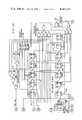
- FIG. 2is a schematic representation of the various elements of the thermostat
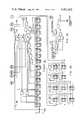
- FIG. 3is an electrical circuit drawing of the offset program timing circuit schematically shown in FIG. 2;
- FIG. 4is a graphical showing of the timing operation of the electrical voltage
- FIG. 5is a graphical showing of changes in the offset program.
- a thermostat 10is shown connected to a temperature conditioning apparatus or furnace 11.
- Thermostat 10is of the type disclosed in the mentioned John T. Adams, et al, patent, having a temperature control point or set point selector 11 for selecting a temperature to be controlled in a space 12.
- a temperature setback, offset or deviation selector switch 13determines the deviation from the normal temperature control point selected by member 11 during preselected offset time periods.
- the thermostathas a pair of indicator means or LED lights 14 and 15 and a plurality of switch buttons 16, the operation of which will be described later.
- thermostat 10has a temperature control or bridge circuit 20 containing a temperature responsive resistance sensor 21 responsive to the temperature in space 12 and an adjustment potentiometer 22 controlled by member 11 to select the normal temperature to be controlled in the space.
- the bridge circuit 20is connected to a control apparatus or unit 23 containing a switch or relay for switching an output at 24 adapted to be connected to temperature conditioning apparatus 17.
- Thermostat 10also contains an offset program timing circuit 25 having an output 30 connected to the bridge circuit of the thermostat for selecting the preselected time period as established by the program timing circuit in which the offset temperature is to be maintained.
- program timing circuit 25is shown with its output 30.
- the program timing circuit 25has a conventional counter chain or timer 31 connected to a signal source 32 of 32,768 Hz.
- the timerhas a normal output at 33 each 7.5 minutes (one pulse each half hour) connected to the input circuit 36 to drive a counter chain twenty-four hour clock 34 in fifteen minute interval steps through a twenty-four hour period of time to provide a pulse for each hour before it resets itself back to zero after 24 hours.
- button or switch 35 of the bank of switches 16 shown in FIGS. 1 and 3is closed to apply a reset signal at 37 to start the twenty-four hour clock from zero and to gate 40 to energize a counter 41.
- indicator light 14is energized each time an hour pulse is provided to counter 41 so that the home owner can count the pulses to indicate the number of hours of desired offset time.
- the count in counter 41is stored in the hours of energy saving memory or count storage 42.
- a program review button or switch 43is closed to energize the counter 41 and a comparator 45 through the review latch 44.
- Counter 41provides a count and energization of count indication light 14. The hour count is compared with the count stored in count storage 42 and when the two are equal, review latch 44 is opened. At the time the clock is pulsing for the count, the home owner observes the number of flashes of the indicator light 14 to inform him of the number of hours stored for the offset time period.
- a window timing circuit or driving means 55receives a repetitive signal or timing pulse T and three different frequency signals through gates 52, 53 and 54 from timer 31. Depending upon which of the three control switches 60, 61 and 63 are closed and for the length of this closure an output conductor 59 controls the signal source output at 32 to shift or drive the twenty-four hour clock 34 to effectively have a different starting time.
- control switch 60When switch 50 is closed to move the stored program ahead, control switch 60 is closed to allow the signal of window timing circuit 55 to admit the output 32 to the twenty-four hour clock.
- the window timing circuit 55receives the timing signal T and the timing signal of gate 54 which allows a 92 pulse signal from output 32.
- the 92 pulse signaldrives the twenty-four hour clock 34 twenty-three hours ahead each time a repetitive action of the pulse of the signal T is allowed to pass through control switch 60.
- indicator light 15At the same time indicator light 15 is momentarily energized for each pulse of signal T.
- the home ownercounts the flashes of light 15, so the number of hours that the program is set ahead can be selected.
- the window timing circuit schematicis shown in FIG.
- Control switch 64allows for a window shown in FIG. 4 sufficient to pass 95 signal pulses from output 32 to drive the twenty-four hour clock twenty-three and three-fourths hours and thus set the program ahead 15 minutes for each pulse of the timing signal T that is allowed to pass through the window control switches.
- an offset time programcan be stored in the thermostat.
- switch 35By closing switch 35 by pushing the button on the front of the thermostat at some particular time, for example, 10:00 P.M.
- switch 35is held closed for eight flashes of indicator light 14.
- twenty-four hour clock 34is started at zero and as the clock runs at a fast rate, each hour output is counted on the counter 41 to provide an output over circuit 70 to energize indicator light 14 on the front of the thermostat.
- switch 35is opened and the eight hour period of time is stored in count storage 42.
- output comparator 46compares the clock time with the count storage.
- Output 30 to the bridge circuit of the thermostatmodifies the control point temperature to some lower selected temperature depending on how much offset was selected at 13 to maintain the lower temperature in space 12. If this were allowed to operate as programmed, the lower temperature would continue until 6:00 A.M. in the morning.
- switch 51is closed to provide for the output of the timing circuit at 32 to enter the twenty-four hour clock for each pulse of the circuit timing signal T and thus each flash of the indicator light 15.
- One flash of light 15, and the clockis moved ahead one hour to have a start time of 9:00 P.M.
Landscapes
- Physics & Mathematics (AREA)
- General Physics & Mathematics (AREA)
- Engineering & Computer Science (AREA)
- Automation & Control Theory (AREA)
- Electric Clocks (AREA)
Abstract
Description
Claims (8)
Priority Applications (1)
| Application Number | Priority Date | Filing Date | Title |
|---|---|---|---|
| US06/389,538US4401262A (en) | 1982-06-18 | 1982-06-18 | Energy saving thermostat with means to shift offset time program |
Applications Claiming Priority (1)
| Application Number | Priority Date | Filing Date | Title |
|---|---|---|---|
| US06/389,538US4401262A (en) | 1982-06-18 | 1982-06-18 | Energy saving thermostat with means to shift offset time program |
Publications (1)
| Publication Number | Publication Date |
|---|---|
| US4401262Atrue US4401262A (en) | 1983-08-30 |
Family
ID=23538681
Family Applications (1)
| Application Number | Title | Priority Date | Filing Date |
|---|---|---|---|
| US06/389,538Expired - Fee RelatedUS4401262A (en) | 1982-06-18 | 1982-06-18 | Energy saving thermostat with means to shift offset time program |
Country Status (1)
| Country | Link |
|---|---|
| US (1) | US4401262A (en) |
Cited By (15)
| Publication number | Priority date | Publication date | Assignee | Title |
|---|---|---|---|---|
| US4632177A (en)* | 1985-03-29 | 1986-12-30 | Honeywell Inc. | Clock operated thermostat having automatic changeover and optimum start |
| US4817705A (en)* | 1987-07-07 | 1989-04-04 | Honeywell Inc. | Thermostatic control without temperature droop using duty cycle control |
| US5278936A (en)* | 1991-12-23 | 1994-01-11 | Steve Shao | Thermostatically controlled portable electric space heater with automatic temperature setback for energy saving |
| US6254009B1 (en)* | 1999-12-08 | 2001-07-03 | Carrier Corporation | Communicating thermostat |
| US6595430B1 (en) | 2000-10-26 | 2003-07-22 | Honeywell International Inc. | Graphical user interface system for a thermal comfort controller |
| US6634566B2 (en) | 2002-02-12 | 2003-10-21 | Carrier Corporation | Advanced setback reporting thermostat |
| US7320110B2 (en) | 2000-11-03 | 2008-01-15 | Honeywell International Inc. | Multiple language user interface for thermal comfort controller |
| US20110184562A1 (en)* | 2010-01-22 | 2011-07-28 | Honeywell International Inc. | Hvac control with utility time of day pricing support |
| US20110184565A1 (en)* | 2010-01-22 | 2011-07-28 | Honeywell International Inc. | Hvac control with utility time of day pricing support |
| US20110184564A1 (en)* | 2010-01-22 | 2011-07-28 | Honeywell International Inc. | Hvac control with utility time of day pricing support |
| US20110238224A1 (en)* | 2010-03-24 | 2011-09-29 | Honeywell International Inc. | Setpoint recovery with utility time of day pricing |
| US9471069B2 (en) | 2003-12-02 | 2016-10-18 | Honeywell International Inc | Configurable thermostat for controlling HVAC system |
| US10082312B2 (en) | 2013-04-30 | 2018-09-25 | Honeywell International Inc. | HVAC controller with multi-region display and guided setup |
| US10302322B2 (en) | 2016-07-22 | 2019-05-28 | Ademco Inc. | Triage of initial schedule setup for an HVAC controller |
| US10436977B2 (en) | 2013-12-11 | 2019-10-08 | Ademco Inc. | Building automation system setup using a remote control device |
Citations (20)
| Publication number | Priority date | Publication date | Assignee | Title |
|---|---|---|---|---|
| US3526887A (en)* | 1967-06-30 | 1970-09-01 | Singer Co | Digit order and decimal point display system and circuit therefor |
| US3925775A (en)* | 1973-10-26 | 1975-12-09 | Ncr Co | Multiple digit display employing single digit readout |
| US4001599A (en)* | 1974-09-17 | 1977-01-04 | Whirlpool Corporation | Appliance programmer with integrated circuit |
| US4035661A (en)* | 1974-06-27 | 1977-07-12 | University Of Alabama In Birmingham | Electronic timer |
| US4041325A (en)* | 1975-06-11 | 1977-08-09 | Thermotrol Corporation | Thermostat timer |
| US4050020A (en)* | 1976-09-17 | 1977-09-20 | General Electric Company | Multiple rate electrical energy metering system and method |
| US4062007A (en)* | 1976-09-17 | 1977-12-06 | P. R. Mallory & Co. Inc. | Solid-state delay timed switching circuit |
| US4079366A (en)* | 1976-05-20 | 1978-03-14 | Gim Wong | Electronic timer and thermoswitch device |
| US4104542A (en)* | 1976-05-19 | 1978-08-01 | Whirlpool Corporation | Program modification circuit for electronic appliance programmer |
| US4134027A (en)* | 1977-07-20 | 1979-01-09 | P.R. Mallory & Co., Inc. | Control system capable of accommodating a plurality of momentary switching devices |
| US4136392A (en)* | 1976-10-29 | 1979-01-23 | Honeywell Inc. | Load cycling with space temperature feedback |
| US4162036A (en)* | 1977-11-14 | 1979-07-24 | Richard R. Balduzzi | Solid state thermostat with digital display |
| US4162610A (en)* | 1975-12-31 | 1979-07-31 | Levine Alfred B | Electronic calendar and diary |
| US4166975A (en)* | 1976-09-17 | 1979-09-04 | General Electric Company | Multiple rate electrical energy metering system and method |
| US4172555A (en)* | 1978-05-22 | 1979-10-30 | Levine Michael R | Adaptive electronic thermostat |
| US4191328A (en)* | 1977-09-01 | 1980-03-04 | Rapidcircuit Corp. | Integral thermostat-digital clock unit |
| US4200910A (en)* | 1977-03-04 | 1980-04-29 | Hall Burness C | Programmable time varying control system and method |
| US4204196A (en)* | 1978-11-17 | 1980-05-20 | Sveda Michael P | Modular electronic timer |
| US4245296A (en)* | 1978-12-11 | 1981-01-13 | Emhart Industries, Inc. | Means and method for controlling the operation of an appliance and the like |
| US4298946A (en)* | 1978-12-18 | 1981-11-03 | Texas Instruments Incorporated | Electronically controlled programmable digital thermostat |
- 1982
- 1982-06-18USUS06/389,538patent/US4401262A/ennot_activeExpired - Fee Related
Patent Citations (20)
| Publication number | Priority date | Publication date | Assignee | Title |
|---|---|---|---|---|
| US3526887A (en)* | 1967-06-30 | 1970-09-01 | Singer Co | Digit order and decimal point display system and circuit therefor |
| US3925775A (en)* | 1973-10-26 | 1975-12-09 | Ncr Co | Multiple digit display employing single digit readout |
| US4035661A (en)* | 1974-06-27 | 1977-07-12 | University Of Alabama In Birmingham | Electronic timer |
| US4001599A (en)* | 1974-09-17 | 1977-01-04 | Whirlpool Corporation | Appliance programmer with integrated circuit |
| US4041325A (en)* | 1975-06-11 | 1977-08-09 | Thermotrol Corporation | Thermostat timer |
| US4162610A (en)* | 1975-12-31 | 1979-07-31 | Levine Alfred B | Electronic calendar and diary |
| US4104542A (en)* | 1976-05-19 | 1978-08-01 | Whirlpool Corporation | Program modification circuit for electronic appliance programmer |
| US4079366A (en)* | 1976-05-20 | 1978-03-14 | Gim Wong | Electronic timer and thermoswitch device |
| US4050020A (en)* | 1976-09-17 | 1977-09-20 | General Electric Company | Multiple rate electrical energy metering system and method |
| US4062007A (en)* | 1976-09-17 | 1977-12-06 | P. R. Mallory & Co. Inc. | Solid-state delay timed switching circuit |
| US4166975A (en)* | 1976-09-17 | 1979-09-04 | General Electric Company | Multiple rate electrical energy metering system and method |
| US4136392A (en)* | 1976-10-29 | 1979-01-23 | Honeywell Inc. | Load cycling with space temperature feedback |
| US4200910A (en)* | 1977-03-04 | 1980-04-29 | Hall Burness C | Programmable time varying control system and method |
| US4134027A (en)* | 1977-07-20 | 1979-01-09 | P.R. Mallory & Co., Inc. | Control system capable of accommodating a plurality of momentary switching devices |
| US4191328A (en)* | 1977-09-01 | 1980-03-04 | Rapidcircuit Corp. | Integral thermostat-digital clock unit |
| US4162036A (en)* | 1977-11-14 | 1979-07-24 | Richard R. Balduzzi | Solid state thermostat with digital display |
| US4172555A (en)* | 1978-05-22 | 1979-10-30 | Levine Michael R | Adaptive electronic thermostat |
| US4204196A (en)* | 1978-11-17 | 1980-05-20 | Sveda Michael P | Modular electronic timer |
| US4245296A (en)* | 1978-12-11 | 1981-01-13 | Emhart Industries, Inc. | Means and method for controlling the operation of an appliance and the like |
| US4298946A (en)* | 1978-12-18 | 1981-11-03 | Texas Instruments Incorporated | Electronically controlled programmable digital thermostat |
Cited By (28)
| Publication number | Priority date | Publication date | Assignee | Title |
|---|---|---|---|---|
| US4632177A (en)* | 1985-03-29 | 1986-12-30 | Honeywell Inc. | Clock operated thermostat having automatic changeover and optimum start |
| US4817705A (en)* | 1987-07-07 | 1989-04-04 | Honeywell Inc. | Thermostatic control without temperature droop using duty cycle control |
| US5278936A (en)* | 1991-12-23 | 1994-01-11 | Steve Shao | Thermostatically controlled portable electric space heater with automatic temperature setback for energy saving |
| US6254009B1 (en)* | 1999-12-08 | 2001-07-03 | Carrier Corporation | Communicating thermostat |
| US20060027671A1 (en)* | 2000-10-26 | 2006-02-09 | Shah Dipak J | Graphical user interface system for a thermal comfort controller |
| US6595430B1 (en) | 2000-10-26 | 2003-07-22 | Honeywell International Inc. | Graphical user interface system for a thermal comfort controller |
| US20070194138A9 (en)* | 2000-10-26 | 2007-08-23 | Shah Dipak J | Graphical user interface system for a thermal comfort controller |
| US7306165B2 (en) | 2000-10-26 | 2007-12-11 | Honeywell International, Inc. | Graphical user interface system for a thermal comfort controller |
| US7360717B2 (en) | 2000-10-26 | 2008-04-22 | Honeywell International Inc. | Graphical user interface system for a thermal comfort controller |
| US20080161978A1 (en)* | 2000-10-26 | 2008-07-03 | Honeywell International Inc. | Graphical user interface system for a thermal comfort controller |
| US20100131884A1 (en)* | 2000-10-26 | 2010-05-27 | Honeywell International Inc. | Graphical user interface system for a thermal comfort controller |
| US7320110B2 (en) | 2000-11-03 | 2008-01-15 | Honeywell International Inc. | Multiple language user interface for thermal comfort controller |
| US6634566B2 (en) | 2002-02-12 | 2003-10-21 | Carrier Corporation | Advanced setback reporting thermostat |
| US9471069B2 (en) | 2003-12-02 | 2016-10-18 | Honeywell International Inc | Configurable thermostat for controlling HVAC system |
| US9733653B2 (en) | 2003-12-02 | 2017-08-15 | Honeywell International Inc. | Interview programming for an HVAC controller |
| US10579078B2 (en) | 2003-12-02 | 2020-03-03 | Ademco Inc. | Interview programming for an HVAC controller |
| US8538586B2 (en) | 2010-01-22 | 2013-09-17 | Honeywell International Inc. | HVAC control with utility time of day pricing support |
| US8185245B2 (en) | 2010-01-22 | 2012-05-22 | Honeywell International Inc. | HVAC control with utility time of day pricing support |
| US8326466B2 (en) | 2010-01-22 | 2012-12-04 | Honeywell International Inc. | HVAC control with utility time of day pricing support |
| US20110184565A1 (en)* | 2010-01-22 | 2011-07-28 | Honeywell International Inc. | Hvac control with utility time of day pricing support |
| US20110184562A1 (en)* | 2010-01-22 | 2011-07-28 | Honeywell International Inc. | Hvac control with utility time of day pricing support |
| US20110184564A1 (en)* | 2010-01-22 | 2011-07-28 | Honeywell International Inc. | Hvac control with utility time of day pricing support |
| US8204628B2 (en) | 2010-03-24 | 2012-06-19 | Honeywell International Inc. | Setpoint recovery with utility time of day pricing |
| US20110238224A1 (en)* | 2010-03-24 | 2011-09-29 | Honeywell International Inc. | Setpoint recovery with utility time of day pricing |
| US10082312B2 (en) | 2013-04-30 | 2018-09-25 | Honeywell International Inc. | HVAC controller with multi-region display and guided setup |
| US10852025B2 (en) | 2013-04-30 | 2020-12-01 | Ademco Inc. | HVAC controller with fixed segment display having fixed segment icons and animation |
| US10436977B2 (en) | 2013-12-11 | 2019-10-08 | Ademco Inc. | Building automation system setup using a remote control device |
| US10302322B2 (en) | 2016-07-22 | 2019-05-28 | Ademco Inc. | Triage of initial schedule setup for an HVAC controller |
Similar Documents
| Publication | Publication Date | Title |
|---|---|---|
| US4401262A (en) | Energy saving thermostat with means to shift offset time program | |
| EP0049626B1 (en) | Temperature control system | |
| US4348582A (en) | Communication via an electricity supply main | |
| US4079366A (en) | Electronic timer and thermoswitch device | |
| US4131786A (en) | Remotely controllable electric oven | |
| US4074117A (en) | Timing system | |
| US3440434A (en) | Apparatus for programming cyclic actuation of valves | |
| WO1980002083A1 (en) | Timer and power control system | |
| US3311303A (en) | Programmer | |
| US4367937A (en) | Motor driven camera | |
| US4672232A (en) | Microprocessor operated timing controller | |
| CA1097510A (en) | Modular electronic timer | |
| US4145617A (en) | Control circuit for providing time selected application of A.C. power | |
| US3778721A (en) | Automatic television programmer | |
| US3604943A (en) | Sprinkler systems and variable timing means | |
| US3271734A (en) | Traffic signal controller | |
| GB2165671A (en) | Timing method & apparatus | |
| US2577296A (en) | Synchronous controller | |
| US4671668A (en) | Timing method and apparatus | |
| EP1006421B1 (en) | Programmable electronic record-and-playback timer for the control of a solenoid valve, particularly for watering systems | |
| US4061902A (en) | Digital traffic coordinator | |
| US4565432A (en) | Motor driven camera | |
| US4076399A (en) | Control mechanism for a plurality of slide projectors | |
| US2832071A (en) | Apparatus for the programmed transmission of coded signals over selected wires | |
| US2902610A (en) | Pulse generating system |
Legal Events
| Date | Code | Title | Description |
|---|---|---|---|
| AS | Assignment | Owner name:HONEYWELL INC., MINNEAPOLIS, MN. A CORP. OF DE. Free format text:ASSIGNMENT OF ASSIGNORS INTEREST.;ASSIGNORS:ADAMS, JOHN T.;NELSON, MARVIN D.;REEL/FRAME:004009/0305 Effective date:19820614 Owner name:HONEYWELL INC., MINNESOTA Free format text:ASSIGNMENT OF ASSIGNORS INTEREST;ASSIGNORS:ADAMS, JOHN T.;NELSON, MARVIN D.;REEL/FRAME:004009/0305 Effective date:19820614 | |
| MAFP | Maintenance fee payment | Free format text:PAYMENT OF MAINTENANCE FEE, 4TH YEAR, PL 96-517 (ORIGINAL EVENT CODE: M170); ENTITY STATUS OF PATENT OWNER: LARGE ENTITY Year of fee payment:4 | |
| FEPP | Fee payment procedure | Free format text:MAINTENANCE FEE REMINDER MAILED (ORIGINAL EVENT CODE: REM.); ENTITY STATUS OF PATENT OWNER: LARGE ENTITY | |
| LAPS | Lapse for failure to pay maintenance fees | ||
| STCH | Information on status: patent discontinuation | Free format text:PATENT EXPIRED DUE TO NONPAYMENT OF MAINTENANCE FEES UNDER 37 CFR 1.362 | |
| FP | Lapsed due to failure to pay maintenance fee | Effective date:19910825 |