US4399820A - Process and device for regulating the stimulation frequency of heart pacemakers - Google Patents
Process and device for regulating the stimulation frequency of heart pacemakersDownload PDFInfo
- Publication number
- US4399820A US4399820AUS06/346,315US34631582AUS4399820AUS 4399820 AUS4399820 AUS 4399820AUS 34631582 AUS34631582 AUS 34631582AUS 4399820 AUS4399820 AUS 4399820A
- Authority
- US
- United States
- Prior art keywords
- measuring probe
- light
- stimulation
- frequency
- measured
- Prior art date
- Legal status (The legal status is an assumption and is not a legal conclusion. Google has not performed a legal analysis and makes no representation as to the accuracy of the status listed.)
- Expired - Lifetime
Links
- 230000000638stimulationEffects0.000titleclaimsabstractdescription57
- 238000000034methodMethods0.000titleclaimsabstractdescription22
- 230000008569processEffects0.000titleclaimsabstractdescription18
- 230000001105regulatory effectEffects0.000titleclaimsabstractdescription9
- 239000000523sampleSubstances0.000claimsabstractdescription69
- 230000008859changeEffects0.000claimsabstractdescription36
- QVGXLLKOCUKJST-UHFFFAOYSA-Natomic oxygenChemical compound[O]QVGXLLKOCUKJST-UHFFFAOYSA-N0.000claimsabstractdescription32
- 229910052760oxygenInorganic materials0.000claimsabstractdescription32
- 239000001301oxygenSubstances0.000claimsabstractdescription32
- 239000008280bloodSubstances0.000claimsabstractdescription25
- 210000004369bloodAnatomy0.000claimsabstractdescription25
- 238000013016dampingMethods0.000claimsabstractdescription3
- 230000005693optoelectronicsEffects0.000claimsabstract2
- 230000033228biological regulationEffects0.000claimsdescription14
- 238000004804windingMethods0.000claimsdescription14
- 238000003860storageMethods0.000claimsdescription13
- 238000005259measurementMethods0.000claimsdescription9
- 230000003287optical effectEffects0.000claimsdescription8
- 238000002513implantationMethods0.000claimsdescription6
- 238000001514detection methodMethods0.000claimsdescription5
- 238000011156evaluationMethods0.000claimsdescription5
- 230000000694effectsEffects0.000claimsdescription4
- 238000009413insulationMethods0.000claimsdescription4
- 230000000717retained effectEffects0.000claimsdescription4
- 230000006978adaptationEffects0.000claimsdescription3
- 230000017531blood circulationEffects0.000claimsdescription3
- 238000011157data evaluationMethods0.000claimsdescription2
- 230000001681protective effectEffects0.000claimsdescription2
- 239000004065semiconductorSubstances0.000claims2
- 239000000470constituentSubstances0.000claims1
- 230000002452interceptive effectEffects0.000claims1
- 230000035515penetrationEffects0.000claims1
- 230000006870functionEffects0.000description7
- 230000007774longtermEffects0.000description6
- 238000010586diagramMethods0.000description4
- 238000010276constructionMethods0.000description3
- 230000008878couplingEffects0.000description3
- 238000010168coupling processMethods0.000description3
- 238000005859coupling reactionMethods0.000description3
- 230000000004hemodynamic effectEffects0.000description3
- 230000014759maintenance of locationEffects0.000description3
- 229910052751metalInorganic materials0.000description3
- 230000005540biological transmissionEffects0.000description2
- 230000001419dependent effectEffects0.000description2
- 238000005516engineering processMethods0.000description2
- 239000011521glassSubstances0.000description2
- 238000004519manufacturing processMethods0.000description2
- 239000000463materialSubstances0.000description2
- 210000004165myocardiumAnatomy0.000description2
- 230000007363regulatory processEffects0.000description2
- 230000004936stimulating effectEffects0.000description2
- KWGRBVOPPLSCSI-WPRPVWTQSA-N(-)-ephedrineChemical compoundCN[C@@H](C)[C@H](O)C1=CC=CC=C1KWGRBVOPPLSCSI-WPRPVWTQSA-N0.000description1
- 108010054147HemoglobinsProteins0.000description1
- 102000001554HemoglobinsHuman genes0.000description1
- 108010064719OxyhemoglobinsProteins0.000description1
- 229910000831SteelInorganic materials0.000description1
- 230000009471actionEffects0.000description1
- 239000000853adhesiveSubstances0.000description1
- 230000001070adhesive effectEffects0.000description1
- 230000008901benefitEffects0.000description1
- 230000000747cardiac effectEffects0.000description1
- 230000001276controlling effectEffects0.000description1
- 230000007423decreaseEffects0.000description1
- 230000003247decreasing effectEffects0.000description1
- 230000002950deficientEffects0.000description1
- 230000006866deteriorationEffects0.000description1
- 230000006872improvementEffects0.000description1
- 238000000691measurement methodMethods0.000description1
- 238000002496oximetryMethods0.000description1
- 230000004044responseEffects0.000description1
- 210000005241right ventricleAnatomy0.000description1
- 239000010959steelSubstances0.000description1
- 230000003797telogen phaseEffects0.000description1
- 210000002620vena cava superiorAnatomy0.000description1
Images

Classifications
- A—HUMAN NECESSITIES
- A61—MEDICAL OR VETERINARY SCIENCE; HYGIENE
- A61N—ELECTROTHERAPY; MAGNETOTHERAPY; RADIATION THERAPY; ULTRASOUND THERAPY
- A61N1/00—Electrotherapy; Circuits therefor
- A61N1/18—Applying electric currents by contact electrodes
- A61N1/32—Applying electric currents by contact electrodes alternating or intermittent currents
- A61N1/36—Applying electric currents by contact electrodes alternating or intermittent currents for stimulation
- A61N1/362—Heart stimulators
- A61N1/365—Heart stimulators controlled by a physiological parameter, e.g. heart potential
- A61N1/36514—Heart stimulators controlled by a physiological parameter, e.g. heart potential controlled by a physiological quantity other than heart potential, e.g. blood pressure
- A61N1/36557—Heart stimulators controlled by a physiological parameter, e.g. heart potential controlled by a physiological quantity other than heart potential, e.g. blood pressure controlled by chemical substances in blood
- A—HUMAN NECESSITIES
- A61—MEDICAL OR VETERINARY SCIENCE; HYGIENE
- A61B—DIAGNOSIS; SURGERY; IDENTIFICATION
- A61B5/00—Measuring for diagnostic purposes; Identification of persons
- A61B5/145—Measuring characteristics of blood in vivo, e.g. gas concentration or pH-value ; Measuring characteristics of body fluids or tissues, e.g. interstitial fluid or cerebral tissue
- A61B5/1455—Measuring characteristics of blood in vivo, e.g. gas concentration or pH-value ; Measuring characteristics of body fluids or tissues, e.g. interstitial fluid or cerebral tissue using optical sensors, e.g. spectral photometrical oximeters
- A61B5/1459—Measuring characteristics of blood in vivo, e.g. gas concentration or pH-value ; Measuring characteristics of body fluids or tissues, e.g. interstitial fluid or cerebral tissue using optical sensors, e.g. spectral photometrical oximeters invasive, e.g. introduced into the body by a catheter
Definitions
- This inventionrelates to a process and a device for regulating the stimulation frequency of heart pacemakers.
- the devicecan thus be used in all patients requiring a heart pacemaker.
- the inventionhas the aim, in heart pacemaker patients, of optimally covering the oxygen demand of the body via the blood circulation, so that the pulse frequency of the heart, as in the natural case, adapts to the particular load conditions, the optimum hemodynamic situation being found by the pacemaker itself.
- the inventionhas, at the same time, the aim of virtually not changing the hitherto well-proved embodiment of the heart pacemakers and the associated pacemaker catheters, so that the known implantation techniques remain the same and, also, the high requirements with respect to the long-term use can be fulfilled.
- the measurement methoddoes not tolerate any changes in the optical transmission path (light guide, reflection space and coupling points), which cause a wavelength-dependent effect on the signal. This can occur through defective coupling points; material changes in the light guide; deposits on the light opening in the catheter, and foreign objects in the reflection region (heart wall, trabeculae).
- control of the pacemaker frequency in dependence on the oxygen saturationcan have disadvantageous consequences if, on advancement of the basic cardiac illness, a change in the relationship of power of the heart to pulse frequency occurs. A deterioration in the hemodynamics can even occur through too great an increase in the frequency.
- the measurement principle and control principlerequire a calibration before the implantation and correspondingly increase the service requirements.
- the catheterhas only a limited serviceability, since the end supports of the light guides become unstable over long periods because they have to accept the greatest part of the tensile strain acting on the catheter.
- the fatigue strength of the light guides for long-term useis not given with the materials available at present, and the necessity of arranging the light aperture laterally in the combination catheter allows no margin technically for the further introduction of a mandrin (steel wire which is pushed into the highly elastic catheter during the implantation, in order more easily to introduce the catheter into the ventricle) beyond this point.
- a mandrinsteel wire which is pushed into the highly elastic catheter during the implantation, in order more easily to introduce the catheter into the ventricle
- the coupling system between the combination catheter and the pacemakeris much more complicated in the production, sensitive in use and voluminous than in the case of conventional pacemaker technology.
- Another object of this inventionis to avoid the disadvantages described above and to provide a measuring process and a device for the determination of the blood oxygen saturation. Another object of the invention is to provide a process and a device for regulating the stimulation frequency of heart pacemakers so that a long-term, undisturbed data acquisition and the best possible hemodynamic situation in the blood circulation are guaranteed, and at the same time the operational safety is not decreased but increased as much as possible, it being intended to employ non-critical servicing and production practices which have been proved technically over long periods of time.
- the present inventionprovides a process for regulating the stimulation frequency of heart pacemakers which comprises the steps of generating with the aid of light emitted by a light-emitting element and reflected by the blood of a patient, in a light-receiving element, a current flow which causes, in a measuring probe, an increasing of the current flow at a constant probe voltage or a damping of the probe voltage at constant current flow; measuring one of the possible changing values; evaluating the change, with time, as a measured quantity proportional to the change, with time, of the blood oxygen saturation, and regulating, as a function of the measured quantity, the stimulation frequency f of the heart pacemaker in such a manner that the greatest possible blood oxygen saturation is always achieved with the lowest stimulation frequency.
- the present inventionprovides a device for the frequency regulation of heart pacemakers having a stimulation frequency which adapts itself to the load conditions of a patient, the central venous blood oxygen saturation being opto-electronically measured as a reference or control quantity for the adaptation, this measurement being carried out with the aid of an intracardiac measuring probe, and the acquisition and evaluation of the measured value occurring by means of a circuit additionally arranged in the heart pacemaker, said device comprising a measuring probe containing at least one combination of a single active light-emitting element and a single active light-receiving element; a control circuit electrically connected to the measuring probe; a stimulation catheter in which the measuring probe is incorporated, and at least two electric lines leading through the stimulation catheter and electrically connecting the measuring probe to the selection circuit of the measuring probe.
- the catheter with the measuring probe according to the inventionis virtually identical in its mechanical construction with the bipolar catheters which have long been in use, and accordingly entails no additional problems with respect to the long-term mechanical strength and the implantation technique and has the best properties with respect to a long-term optical measurement of the blood oxygen saturation.
- the data acquisitionmakes it possible to manage with only two electric lines (wire windings) in the catheter, and thus to use the well-proved catheter techniques.
- the data processingmakes it possible to measure, with uniform accuracy, normal variations with time in the body load of the patient, independently of very short or long-term changes along the measuring distance.
- the regulating process for adapting the stimulation frequency to the loads of the patientmakes possible a direct re-adjustment in the case of variations in the load as well as an autonomous optimum regulation in the context of a best possible oxygen supply with as small a heart load as possible, thus as low a stimulation frequency as possible.
- the detection of errorsmakes possible the recognition of failures in the data acquisition and evaluation and due to breaks in the electric lines in the catheter, and makes possible the known use of two lines for the vital stimulation.
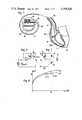
- FIG. 1is a diagrammatic view showing a heart pacemaker with a stimulation catheter and measuring probe for stimulation of a heart muscle;
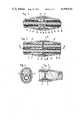
- FIG. 2is a longitudinal section, on an enlarged scale, through the measuring probe provided by concentrically arranged electric lines in the form or wire windings;
- FIG. 3is a longitudinal section through a further embodiment of a measuring probe with electric lines in the form of wire windings arranged in parallel;
- FIG. 4is a section along line IV--IV of FIG. 3;
- FIG. 5is a section along line V--V of FIG. 3;
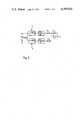
- FIG. 6is a schematic diagram of a control circuit of the measuring probe
- FIG. 7is a circuit of the measuring probe
- FIG. 8is a diagrammatic view showing the current-voltage characteristics of the measuring probe
- FIG. 9is a schematic diagram of a signal converter circuit
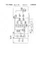
- FIG. 10is a block diagram of a heart pacemaker
- FIG. 11is a schematic diagram of the variation of the stimulation frequency with time, as a function of the central venous blood oxygen saturation.
- FIG. 1shows a heart pacemaker HS containing a power supply component Ba, an electronic circuit component Sch and a bipolar electrical connector EK.
- a bipolar electrical plug ES of a stimulation catheter Kis firmly screwed into the electrical connector EK.
- the stimulation catheter Kleads via the superior vena cava HV into the right auricle RV and then into the right ventricle RHK of a patient, so that, at this point, the blood oxygen saturation is measured by a measuring probe M and the heart muscle H is stimulated by a stimulation electrode E.
- FIG. 2 and in FIGS. 3 to 5Two embodiments of a measuring probe are shown in more detail in FIG. 2 and in FIGS. 3 to 5, respectively.
- the two electric linesare wire windings 30 and 36.
- the wire windings 30 and 36are arranged concentrically with one another in the embodiment shown in FIG. 2, whereas in the embodiment shown in FIGS. 3, 4 and 5 wire windings 30 1 and 36 1 are used which extend parallel to each other.
- both wire windings 30 or 30 1 and 36 or 36 1serve as a supply line to the stimulation electrode E and also as the current supply to the measuring probe M.
- the electrical contact with the measuring probe Moccurs via a first metallic annular element 31 in FIG. 2 and a first metallic annular element 31 1 in FIG. 3.
- This first annular elementhas an inner thread which ensures a permanent pressure contact, and simultaneously serves as a carrier for at least one light-transmitting element 32 which is a red-light-emitting diode in each case and which is in contact, e.g. in adhesive contact, at the cathode side, with the first metallic annular element.
- the first metallic annular elementis electrically connected, via threaded and/or pressure contact, with a wire winding 33 in FIG. 2 and 33 1 in FIG. 3 each of which also leads to the stimulation electrode E and is provided as a spare component, as a safety device for the stimulation.
- An annular insulation 35 in FIG. 2 and 35 1 in FIG. 3 which is firmly adhesively bondedis mounted between the plug-side part of the first metallic annular element and a second annular metallic element 34 in FIG. 2 and 34 1 in FIG. 3.
- the second annular metallic elementhas threaded and/or pressure contact with the probe line, i.e. with the wire winding 36 in FIG. 2 and 36 1 in FIG.
- a bridging diode D onot shown in FIGS. 2 and 3 is not integrated in the light-receiving element or the light-emitting element it must be additionally attached, as an individual element, to one of the two annular elements 31 or 34 in FIG. 2 or 31 1 or 34 1 in FIG. 3.
- the second supply line to the light-emitting and light-receiving elements 32 and 37 (or to the bridging diode)is, in each case, a bond wire 38 from the opposite annular element.
- a transparent protective jacket 39surrounds the body of the measuring probe composed of the two annular metallic elements, the glass ring 39 being firmly welded at its edges to the metallic annular elements which are mutually insulated.
- An electrically insulating tube 40serves as an insulation between the supply lines, i.e. the wire windings, and, on the other hand, an outer transparent insulating tube 41 serves as an insulation, from the exterior.
- FIG. 7shows the circuit of the measuring probe M consisting of the light-emitting element 32 in the form of a light diode, the light receiving element 37 in the form of a npn-photo transistor, and the bridging diode D o .
- the functional principle of the measuring probe Mcan be recognized with reference to its current-voltage characteristics 42 and 43. If a reflecting object 44 is lacking in the measuring arrangement of FIG. 7, the I-U characteristic 42 results. However, if light from a reflecting object 44 (in the present case, blood) strikes the light-receiving element 37, the I-U characteristic 43 results.
- the intensity of the reflected lightis thus proportional to the change in the voltage ⁇ U S , and correspondingly, at constant voltage U K , proportional to the current change ⁇ I S .
- FIG. 6shows by way of example an embodiment of a control circuit of the measuring probe, which circuit produces a pulse with a constant voltage characteristic at the supply lines, i.e. at the wire windings, to the measuring probe, so that the characteristic (response) curve of the current I S through the measuring probe is dependent on the reflected light accepted by the measuring probe and thus also the voltage characteristic at a load resistance R v .
- the probe voltage U Sreaches a fixed value U K
- the measured voltage U M at this momentis:
- the reflection factor of the bloodis a function of the blood oxygen saturation.
- FIG. 9shows the functional principle for an analog circuitry of the signal converter 8.
- the measured signal U Mconsisting of a positive measured pulse U MM arriving in the pulse phase T 1 and a negative error-detection pulse -U MF arriving in the pulse phase T 2 , is thus received by two sample and hold circuits S+H 1 and S+H 2 so that the storage S+H 1 stores the amplitude of the measured pulse U MM via a switch S 1 closed in the pulse phase T 1 and the other storage S+H 2 stores the amplitude of the error-detection pulse -U MF via a switch S 2 closed in the pulse phase T 2 .
- the signal values U M and U MFare evaluated in such a manner that the measuring error included in the measured pulse and caused by changes in the resistance of the wire windings 30, 30 1 and 36, 36 1 and a temperature drift of the optical measuring probe M is eliminated.
- FIG. 10The most important functions of the heart pacemaker according to the invention are represented in FIG. 10.
- the areas enclosed by broken linesindicate the major functional units and denote, in particular:
- a fixed-frequency pulse generator 1gives the time base for a program control 2 which controls all the measuring and regulating processes of the pacemaker circuit.
- the program control 2starts the transmission of the stimulation pulse by a stimulation pulse generator 4 via a stimulation electrode 5, and directly subsequently the measurement of the blood oxygen saturation via the measuring probe M with a measuring probe control circuit 7.
- the measured signalis evaluated and amplified in a signal converter 8 and, in the case of using digital data processing, is converted into digital form.
- An integrator 9forms the average value of the measured signals over a prescribed period of time.
- Storages 10 to 15accept the integrated signal value, the storages 10 and 11 alternately in time period ⁇ t 1 and the storages 12 and 13 alternately in time period ⁇ t 4 .
- the highest measured signal value occurring in a prescribed time range ⁇ t 0is stored in the maximum value storage 14, and the lowest value in each case is stored in the minimum value storage 15.
- a difference-former 16the difference ⁇ S 02 in the measured value between the new and each of the previous measured signals in storage 10 or storage 11 is determined and in a difference-former 17 the difference in the measured value between the contents of storage 12 or 13 is determined.
- a comparator 21determines whether the change in the normalized measured quantity ⁇ B S1 with time is larger or smaller than a predetermined value +A 1 or -A 1 .
- a changeis effected in the stimulating frequency by a positive value + ⁇ f in the case in which ⁇ B S1 ⁇ -A 1 and by a negative value - ⁇ f in the case in which ⁇ B S1>+A 1 , and the sign of the change is stored in a storage 24.
- a change in the stimulation frequencyis automatically initiated in the frequency control 23, after a fixed predetermined time interval ⁇ t 5 , the sign of the change being opposite to that which is retained in the storage 24, as long as the tendency control 25 does not effect a repetition of the sign.
- a comparator 22assesses whether the change in the measured quantity ⁇ B S4 is larger than a fixed value A 2 or smaller than -A 2 , whereupon the preceding frequency change is either reversed or remains.
- An error detection 26compares the signal received by the data evaluation with allowed limiting values and sets the stimulation frequency generator 3 to a fixed frequency f 0 if these limiting values are exceeded, and short-circuits, via a switch 27, the two catheter connections, whereby the measurement and regulation are put out of action.
- an electrocardiogram amplifier 28the intrinsic activity of the heart is monitored between the stimulations, and, in the case of a self-excitation of the heart, the stimulation by the pulse generator is hindered via a comparator 29.
- FIG. 11shows the regulation, according to the invention, of the heart pacemaker stimulation frequency f as a function of the load of the patient, represented by the relationship in the variation, with time, of the measured value of the blood oxygen saturation S 02 , the changes therein per time unit ⁇ t 1 and ⁇ t 4 , and the change in the frequency f effected thereby.
- the central venous oxygen saturation S 02decreases, that is to say, the change per time unit ⁇ t 1 , relative to a maximum variation range ⁇ S 02max / ⁇ t 0 between the limiting values S 02max and S 02min , gives a negative value for B S1 . If this is smaller than -A 1 , a frequency change by + ⁇ f 1 follows automatically during the course of the time interval ⁇ t 2 .
- the optimum regulationbegins, in particular always with a positive frequency change + ⁇ f 2 after ⁇ t 5 , at first, to provide a better supply of oxygen. If this + ⁇ f 2 causes an increase in the S 02 value during the course of the time unit ⁇ t 4 , and if this value--again relative to ⁇ S 02max / ⁇ t 4 is greater than a fixed value +A 2 , the frequency change is retained and initiated at the same time, owing to the positive result, a further increase of frequency by ⁇ f 2 after further ⁇ t 5 .
Landscapes
- Health & Medical Sciences (AREA)
- Life Sciences & Earth Sciences (AREA)
- Physics & Mathematics (AREA)
- Cardiology (AREA)
- Heart & Thoracic Surgery (AREA)
- Public Health (AREA)
- General Health & Medical Sciences (AREA)
- Veterinary Medicine (AREA)
- Biophysics (AREA)
- Animal Behavior & Ethology (AREA)
- Engineering & Computer Science (AREA)
- Biomedical Technology (AREA)
- Molecular Biology (AREA)
- Spectroscopy & Molecular Physics (AREA)
- General Chemical & Material Sciences (AREA)
- Nuclear Medicine, Radiotherapy & Molecular Imaging (AREA)
- Physiology (AREA)
- Chemical Kinetics & Catalysis (AREA)
- Chemical & Material Sciences (AREA)
- Radiology & Medical Imaging (AREA)
- Optics & Photonics (AREA)
- Pathology (AREA)
- Medical Informatics (AREA)
- Hematology (AREA)
- Surgery (AREA)
- Measurement Of The Respiration, Hearing Ability, Form, And Blood Characteristics Of Living Organisms (AREA)
- Electrotherapy Devices (AREA)
Abstract
Description
f=k·S.sub.O2, wherein f.sub.min <f<f.sub.max.
U.sub.M =I.sub.S ·R.sub.v
Claims (18)
|B.sub.S1 |>A.sub.1
|B.sub.S1 |<A.sub.1,
+B.sub.S4 >A.sub.2 after +(Δf.sub.2 /Δt.sub.3)
B.sub.S4 >-A.sub.2 after -(Δf.sub.2 /Δt.sub.3).
Applications Claiming Priority (2)
| Application Number | Priority Date | Filing Date | Title |
|---|---|---|---|
| DE3107128ADE3107128C2 (en) | 1981-02-26 | 1981-02-26 | Control circuit for adapting the stimulation frequency of a cardiac pacemaker to the load on a patient |
| DE3107128 | 1981-02-26 |
Publications (1)
| Publication Number | Publication Date |
|---|---|
| US4399820Atrue US4399820A (en) | 1983-08-23 |
Family
ID=6125760
Family Applications (1)
| Application Number | Title | Priority Date | Filing Date |
|---|---|---|---|
| US06/346,315Expired - LifetimeUS4399820A (en) | 1981-02-26 | 1982-02-05 | Process and device for regulating the stimulation frequency of heart pacemakers |
Country Status (6)
| Country | Link |
|---|---|
| US (1) | US4399820A (en) |
| EP (1) | EP0059868B1 (en) |
| JP (1) | JPS57192569A (en) |
| AU (1) | AU550489B2 (en) |
| DE (2) | DE3107128C2 (en) |
| IE (1) | IE52671B1 (en) |
Cited By (102)
| Publication number | Priority date | Publication date | Assignee | Title |
|---|---|---|---|---|
| US4436092A (en) | 1982-05-19 | 1984-03-13 | Purdue Research Foundation | Exercise responsive cardiac pacemaker |
| US4535774A (en)* | 1983-06-30 | 1985-08-20 | Medtronic, Inc. | Stroke volume controlled pacer |
| US4543954A (en)* | 1982-05-19 | 1985-10-01 | Purdue Research Foundation | Exercise responsive cardiac pacemaker |
| US4543955A (en)* | 1983-08-01 | 1985-10-01 | Cordis Corporation | System for controlling body implantable action device |
| US4722342A (en)* | 1986-06-16 | 1988-02-02 | Siemens Aktiengesellschaft | Cardiac pacer for pacing a human heart and pacing method |
| US4726383A (en)* | 1982-05-19 | 1988-02-23 | Purdue Research Foundation | Exercise-responsive cardiac pacemaker lead |
| US4727879A (en)* | 1985-10-17 | 1988-03-01 | Siemens Aktiengesellschaft | Measurement device for intracardial acquisition of blood oxygen saturation |
| US4730389A (en)* | 1986-08-15 | 1988-03-15 | Medtronic, Inc. | Method for fabrication of an implantable hermetic transparent container |
| US4750495A (en)* | 1987-06-05 | 1988-06-14 | Medtronic, Inc. | Oxygen sensing pacemaker |
| EP0257954A3 (en)* | 1986-08-15 | 1988-08-10 | Medtronic, Inc. | Oxygen sensing pacemaker |
| US4763655A (en)* | 1986-06-16 | 1988-08-16 | Siemens Aktiengesellschaft | Frequency-controlled heart pacemaker |
| US4776338A (en)* | 1986-06-16 | 1988-10-11 | Siemens Aktiengesellschaft | Cardiac pacer for pacing a human heart and pacing method |
| US4790318A (en)* | 1986-06-16 | 1988-12-13 | Siemens Aktiengesellschaft | Cardiac pacer for pacing a human heart |
| US4791935A (en)* | 1986-08-15 | 1988-12-20 | Medtronic, Inc. | Oxygen sensing pacemaker |
| US4807632A (en)* | 1986-05-22 | 1989-02-28 | Siemens Aktiengesellschaft | Measuring instrument for intracardial acquisition of the blood oxygen saturation of a patient for controlling the pacing rate of a heart pacemaker |
| US4807629A (en)* | 1986-08-15 | 1989-02-28 | Medtronic, Inc. | Oxygen sensing pacemaker |
| US4813421A (en)* | 1986-08-15 | 1989-03-21 | Medtronic, Inc. | Oxygen sensing pacemaker |
| US4815469A (en)* | 1987-10-08 | 1989-03-28 | Siemens-Pacesetter, Inc. | Implantable blood oxygen sensor and method of use |
| US4827933A (en)* | 1986-10-30 | 1989-05-09 | Telectronics N.V. | Apparatus and method for adjusting heart/pacer rate relative to cardiac pO2 obtain a required cardiac output |
| US4830488A (en)* | 1986-06-16 | 1989-05-16 | Siemens Aktiengesellschaft | Measuring instrument for intracardial acquisition of blood oxygen saturation |
| EP0215730A3 (en)* | 1985-09-17 | 1989-06-07 | Biotronik Mess- Und Therapiegerate Gmbh & Co Ingenieurburo Berlin | Heart stimulator |
| US4870968A (en)* | 1984-06-20 | 1989-10-03 | Siemens Aktiengesellschaft | System and method for controlling the stimulation frequency of heart pacemakers |
| US4877032A (en)* | 1986-06-16 | 1989-10-31 | Siemens Aktiengesellschaft | Sensor arrangement for the control of implantable devices |
| US4903701A (en)* | 1987-06-05 | 1990-02-27 | Medtronic, Inc. | Oxygen sensing pacemaker |
| EP0325851A3 (en)* | 1988-01-29 | 1990-05-23 | Telectronics N.V. | Rate-responsive, distributed-rate pacemaker |
| EP0314937A3 (en)* | 1987-10-08 | 1990-05-23 | Siemens Elema Ab | Implantable blood oxygen sensor and method of use |
| US5003976A (en)* | 1987-09-28 | 1991-04-02 | Eckhard Alt | Cardiac and pulmonary physiological analysis via intracardiac measurements with a single sensor |
| US5040538A (en)* | 1989-09-05 | 1991-08-20 | Siemens-Pacesetter, Inc. | Pulsed light blood oxygen content sensor system and method of using same |
| US5058586A (en)* | 1987-07-27 | 1991-10-22 | Siemens Aktiengesellschaft | Catheter for implantation in the heart, having an integrated measuring probe |
| US5076271A (en)* | 1990-07-19 | 1991-12-31 | Siemens-Pacesetter, Inc. | Rate-responsive pacing method and system employing minimum blood oxygen saturation as a control parameter and as a physical activity indicator |
| US5113862A (en)* | 1990-09-25 | 1992-05-19 | Siemens Pacesetter, Inc. | Blood oxygen sensor having leakage compensation |
| US5133349A (en)* | 1988-02-05 | 1992-07-28 | Siemens Aktiengesellschaft | Method for adapting the stimulation frequency of a heart pacemaker to the burden of the patient |
| EP0518364A2 (en) | 1991-06-14 | 1992-12-16 | Pacesetter, Inc. | Pacemaker lead for sensing a physiologic parameter of the body |
| US5176138A (en)* | 1991-03-21 | 1993-01-05 | Siemens Pacesetter, Inc. | Implantable pacemaker having means for automatically adjusting stimulation energy as a function of sensed so2 |
| US5186169A (en)* | 1987-11-13 | 1993-02-16 | Biotronik Mess- Und Therapiegerate Gmbh & Co. | Common signal transmission path cardiac pacemaker with switchable capacitors |
| US5218961A (en)* | 1990-09-28 | 1993-06-15 | Siemens Aktiengesellschaft | Apparatus for in vivo intracardial of a measured signal corresponding to the physical activity of a subject and a heart pacemaker having a stimulation rate controlled thereby |
| US5235976A (en)* | 1991-12-13 | 1993-08-17 | Cardiac Pacemakers, Inc. | Method and apparatus for managing and monitoring cardiac rhythm using active time as the controlling parameter |
| US5275171A (en)* | 1990-08-06 | 1994-01-04 | Siemens Pacesetter, Inc. | Implantable lead and sensor |
| US5282464A (en)* | 1992-07-21 | 1994-02-01 | Brain Archibald Ian Jeremy | Combined laryngeal mask and reflectance oximeter |
| US5405364A (en)* | 1992-06-09 | 1995-04-11 | Siemens Aktiengesellschaft | Method and arrangement for calculating a physiological function parameter of a life form for therapy control |
| US5411532A (en)* | 1993-06-04 | 1995-05-02 | Pacesetter, Inc. | Cardiac pacemaker having integrated pacing lead and oxygen sensor |
| US5423869A (en)* | 1993-01-21 | 1995-06-13 | Pacesetter, Inc. | Multi-sensor rate-responsive pacemaker and method of operating same |
| US5571164A (en)* | 1994-09-29 | 1996-11-05 | Pacesetter Ab | Cardiac electrode device having at least a portion thereof which is ribbon shaped |
| US5593430A (en)* | 1995-01-27 | 1997-01-14 | Pacesetter, Inc. | Bus system for interconnecting an implantable medical device with a plurality of sensors |
| WO1999011174A1 (en) | 1997-09-03 | 1999-03-11 | Medtronic, Inc. | Optical window for implantable medical devices |
| WO2000040296A1 (en)* | 1999-01-05 | 2000-07-13 | St. Jude Medical Ab | Cardiac pacemaker |
| US6125291A (en)* | 1998-10-30 | 2000-09-26 | Medtronic, Inc. | Light barrier for medical electrical lead oxygen sensor |
| US6125290A (en)* | 1998-10-30 | 2000-09-26 | Medtronic, Inc. | Tissue overgrowth detector for implantable medical device |
| US6134459A (en)* | 1998-10-30 | 2000-10-17 | Medtronic, Inc. | Light focusing apparatus for medical electrical lead oxygen sensor |
| US6144866A (en)* | 1998-10-30 | 2000-11-07 | Medtronic, Inc. | Multiple sensor assembly for medical electric lead |
| US6163723A (en)* | 1998-10-22 | 2000-12-19 | Medtronic, Inc. | Circuit and method for implantable dual sensor medical electrical lead |
| US6188927B1 (en) | 1999-04-16 | 2001-02-13 | Pacesetter, Inc. | Implantable cardiac stimulation system having improved method of calibrating physiologic sensors |
| US6198952B1 (en) | 1998-10-30 | 2001-03-06 | Medtronic, Inc. | Multiple lens oxygen sensor for medical electrical lead |
| US6248080B1 (en) | 1997-09-03 | 2001-06-19 | Medtronic, Inc. | Intracranial monitoring and therapy delivery control device, system and method |
| US6314322B1 (en) | 1998-03-02 | 2001-11-06 | Abiomed, Inc. | System and method for treating dilated cardiomyopathy using end diastolic volume (EDV) sensing |
| WO2002005893A1 (en) | 2000-07-14 | 2002-01-24 | Cardiac Pacemakers, Inc. | Method and apparatuses for monitoring hemodynamic activities using an intracardiac impedance-derived parameter |
| US20030093130A1 (en)* | 2001-11-09 | 2003-05-15 | Medtronic, Inc. | Multiplexed electrode array extension |
| US6731976B2 (en) | 1997-09-03 | 2004-05-04 | Medtronic, Inc. | Device and method to measure and communicate body parameters |
| US20040176818A1 (en)* | 2002-12-09 | 2004-09-09 | Wahlstrand Carl D. | Modular implantable medical device |
| US20040215049A1 (en)* | 2003-01-24 | 2004-10-28 | Proteus Biomedical, Inc. | Method and system for remote hemodynamic monitoring |
| US20040220637A1 (en)* | 2003-01-24 | 2004-11-04 | Proteus Biomedical, Inc. | Method and apparatus for enhancing cardiac pacing |
| US20040254483A1 (en)* | 2003-01-24 | 2004-12-16 | Proteus Biomedical, Inc. | Methods and systems for measuring cardiac parameters |
| US20040267321A1 (en)* | 2003-06-26 | 2004-12-30 | Peter Boileau | Method and apparatus for monitoring drug effects on cardiac electrical signals using an implantable cardiac stimulation device |
| US20050004619A1 (en)* | 2003-05-16 | 2005-01-06 | Wahlstrand Carl D. | Headset recharger for cranially implantable medical devices |
| US20050004637A1 (en)* | 2003-05-16 | 2005-01-06 | Ruchika Singhal | Explantation of implantable medical device |
| US20050004618A1 (en)* | 2003-05-16 | 2005-01-06 | Scott Erik R. | Implantable medical device with a nonhermetic battery |
| US6952612B1 (en) | 2002-04-24 | 2005-10-04 | Pacesetter, Inc. | Method and apparatus for programming a rate responsive implantable cardiac stimulation device using user specified rate response functions |
| US7013178B2 (en) | 2002-09-25 | 2006-03-14 | Medtronic, Inc. | Implantable medical device communication system |
| US20060058588A1 (en)* | 2004-09-02 | 2006-03-16 | Proteus Biomedical, Inc. | Methods and apparatus for tissue activation and monitoring |
| US20060149145A1 (en)* | 2002-10-24 | 2006-07-06 | Furnary Anthony P | Method and apparatus for monitoring blood condition and cardiopulmonary function |
| US7092757B2 (en) | 2002-07-12 | 2006-08-15 | Cardiac Pacemakers, Inc. | Minute ventilation sensor with dynamically adjusted excitation current |
| US7101339B2 (en) | 2002-12-13 | 2006-09-05 | Cardiac Pacemakers, Inc. | Respiration signal measurement apparatus, systems, and methods |
| US7136704B2 (en) | 2003-04-16 | 2006-11-14 | Alfred E. Mann Foundation For Scientific Research | Blood oxygen monitoring system and a lead therefor |
| US7139613B2 (en) | 2002-09-25 | 2006-11-21 | Medtronic, Inc. | Implantable medical device communication system with pulsed power biasing |
| US20070156085A1 (en)* | 2005-12-30 | 2007-07-05 | Schulhauser Randal C | Implantable perfusion sensor |
| US20070179552A1 (en)* | 2006-01-30 | 2007-08-02 | Dennis Charles L | Intravascular medical device |
| CN100337512C (en)* | 2001-07-09 | 2007-09-12 | 威德克斯公司 | Hearing aid and a method for testing a hearing aid |
| US20070239053A1 (en)* | 2006-03-31 | 2007-10-11 | Sourav Bhunia | Method and apparatus for verifying a determined cardiac event in a medical device based on detected variation in hemodynamic status |
| US7286884B2 (en) | 2004-01-16 | 2007-10-23 | Medtronic, Inc. | Implantable lead including sensor |
| US7596399B2 (en) | 2004-04-29 | 2009-09-29 | Medtronic, Inc | Implantation of implantable medical device |
| US7596408B2 (en) | 2002-12-09 | 2009-09-29 | Medtronic, Inc. | Implantable medical device with anti-infection agent |
| US20090287266A1 (en)* | 2008-05-13 | 2009-11-19 | Mark Zdeblick | High-voltage tolerant multiplex multi-electrode stimulation systems and methods for using the same |
| US20100130839A1 (en)* | 2007-04-27 | 2010-05-27 | St. Jude Medical Ab | Implantable devices and method for determining a concentration of a substance and/or molecule in blood or tissue of a patient |
| US20100317943A1 (en)* | 2009-06-10 | 2010-12-16 | Kuhn Jonathan L | Active Noise Cancellation in an Optical Sensor Signal |
| US20100317940A1 (en)* | 2009-06-10 | 2010-12-16 | Kuhn Jonathan L | Absolute calibrated tissue oxygen saturation and total hemoglobin volume fraction |
| US20100317939A1 (en)* | 2009-06-10 | 2010-12-16 | Kuhn Jonathan L | Device and Method for Monitoring of Absolute Oxygen Saturation and Tissue Hemoglobin Concentration |
| US20100318146A1 (en)* | 2009-06-10 | 2010-12-16 | Can Cinbis | Tissue Oxygenation Monitoring in Heart Failure |
| US20100318149A1 (en)* | 2009-06-10 | 2010-12-16 | Kuhn Jonathan L | Shock Reduction Using Absolute Calibrated Tissue Oxygen Saturation and Total Hemoglobin Volume Fraction |
| US20110066204A1 (en)* | 2009-09-11 | 2011-03-17 | Kuhn Jonathan L | Method and apparatus for post-shock evaluation using tissue oxygenation measurements |
| US7983751B2 (en) | 2005-08-12 | 2011-07-19 | Proteus Biomedical, Inc. | Measuring conduction velocity using one or more satellite devices |
| US8036743B2 (en) | 2005-03-31 | 2011-10-11 | Proteus Biomedical, Inc. | Automated optimization of multi-electrode pacing for cardiac resynchronization |
| US8306621B2 (en) | 2003-07-02 | 2012-11-06 | Cardiac Pacemakers, Inc. | Cardiac cycle synchronized sampling of impedance signal |
| US8355784B2 (en) | 2011-05-13 | 2013-01-15 | Medtronic, Inc. | Dynamic representation of multipolar leads in a programmer interface |
| US8396563B2 (en) | 2010-01-29 | 2013-03-12 | Medtronic, Inc. | Clock synchronization in an implantable medical device system |
| US8412347B2 (en) | 2009-04-29 | 2013-04-02 | Proteus Digital Health, Inc. | Methods and apparatus for leads for implantable devices |
| US8473069B2 (en) | 2008-02-28 | 2013-06-25 | Proteus Digital Health, Inc. | Integrated circuit implementation and fault control system, device, and method |
| US8712549B2 (en) | 2002-12-11 | 2014-04-29 | Proteus Digital Health, Inc. | Method and system for monitoring and treating hemodynamic parameters |
| US8718770B2 (en) | 2010-10-21 | 2014-05-06 | Medtronic, Inc. | Capture threshold measurement for selection of pacing vector |
| US8786049B2 (en) | 2009-07-23 | 2014-07-22 | Proteus Digital Health, Inc. | Solid-state thin-film capacitor |
| US9084901B2 (en)* | 2006-04-28 | 2015-07-21 | Medtronic, Inc. | Cranial implant |
| US9162072B2 (en) | 2004-04-30 | 2015-10-20 | Medtronic, Inc. | Implantable medical device with lubricious material |
| US9393432B2 (en) | 2008-10-31 | 2016-07-19 | Medtronic, Inc. | Non-hermetic direct current interconnect |
Families Citing this family (16)
| Publication number | Priority date | Publication date | Assignee | Title |
|---|---|---|---|---|
| GB8416219D0 (en)* | 1984-06-26 | 1984-08-01 | Antec Systems | Patient monitoring apparatus |
| US4467807A (en)* | 1981-11-23 | 1984-08-28 | Medtronic, Inc. | Rate adaptive demand pacemaker |
| DE3241251A1 (en)* | 1982-11-09 | 1984-05-24 | Stöckert-Instrumente Apparatebau GmbH & Co Fertigungs- u. Vertriebs KG, 8000 München | Transvenous implantable pacemaker electrode |
| US4576183A (en)* | 1983-09-21 | 1986-03-18 | Gianni Plicchi | Electronic circuit for monitoring respiratory parameter for controlling operation of implantable medical device |
| DE3419439C1 (en)* | 1984-05-24 | 1985-11-21 | Eckhard Dr. 8000 München Alt | Frequency-dependent pacemaker depending on the load |
| US4566456A (en)* | 1984-10-18 | 1986-01-28 | Cordis Corporation | Apparatus and method for adjusting heart/pacer rate relative to right ventricular systolic pressure to obtain a required cardiac output |
| IT1202151B (en)* | 1985-06-05 | 1989-02-02 | Gino Grassi | CARDIAC STIMULATOR OR PACEMAKER WITH CIRCADIAN PARA-PHYSIOLOGICAL BEHAVIOR |
| DE3772669D1 (en)* | 1986-08-18 | 1991-10-10 | Siemens Ag | MEASURING DEVICE FOR CONTROLLING IMPLANTABLE BODY SPARE PARTS. |
| DE3709022A1 (en)* | 1987-03-19 | 1988-09-29 | Alt Eckhard | Frequency-variable pacemaker |
| WO1992005836A1 (en)* | 1990-10-04 | 1992-04-16 | Siemens-Elema Ab | Arrangement, in particular heart pacemaker, for recording a heart activity measurement parameter |
| DE4141113A1 (en)* | 1991-12-13 | 1993-06-17 | Hornschuch Ag K | LARGE-SIDED COVERING PARTS MADE OF THERMOPLASTIC PLASTICS FOR THE INTERIOR OF THE VEHICLE AND METHOD FOR THE PRODUCTION THEREOF |
| US5634461A (en)* | 1995-06-07 | 1997-06-03 | Alliance Pharmaceutical Corp. | System for measuring blood oxygen levels |
| US6390977B1 (en) | 1995-06-07 | 2002-05-21 | Alliance Pharmaceutical Corp. | System and methods for measuring oxygenation parameters |
| US6860266B2 (en) | 2000-11-03 | 2005-03-01 | Dartmouth-Hitchcock Clinic | Physiological object displays |
| US6743172B1 (en) | 1998-01-14 | 2004-06-01 | Alliance Pharmaceutical Corp. | System and method for displaying medical process diagrams |
| DE19804843A1 (en)* | 1998-01-29 | 1999-08-05 | Biotronik Mess & Therapieg | Self-calibrating rate-adaptive pacemaker |
Citations (2)
| Publication number | Priority date | Publication date | Assignee | Title |
|---|---|---|---|---|
| DE2741981A1 (en)* | 1976-10-18 | 1978-04-20 | Oximetrix | METHOD AND DEVICE FOR DETERMINING THE OXYGEN CONTENT IN THE BLOOD |
| US4202339A (en)* | 1977-04-21 | 1980-05-13 | Alexander Wirtzfeld | Cardiac pacemaker |
Family Cites Families (5)
| Publication number | Priority date | Publication date | Assignee | Title |
|---|---|---|---|---|
| US3647299A (en)* | 1970-04-20 | 1972-03-07 | American Optical Corp | Oximeter |
| US3804098A (en)* | 1972-04-17 | 1974-04-16 | Medronic Inc | Body implantable lead |
| IT1028812B (en)* | 1975-04-24 | 1979-02-10 | Alcidi M | PERFECTED ARTIFICIAL PACEMAKER |
| DE2609365A1 (en)* | 1976-03-06 | 1977-09-08 | Georg Dr Med Csapo | Heart pacemaker with frequency increasing with body's demands - is controlled by changes in blood temp. measured at heart region |
| DE2820867A1 (en)* | 1978-05-10 | 1979-11-15 | Biotronik Mess & Therapieg | Heart pacemaker electrode supply lead - comprises parallel conductive coils joined at ends and deforming independently |
- 1981
- 1981-02-26DEDE3107128Apatent/DE3107128C2/ennot_activeExpired
- 1982
- 1982-02-05USUS06/346,315patent/US4399820A/ennot_activeExpired - Lifetime
- 1982-02-19EPEP82101259Apatent/EP0059868B1/ennot_activeExpired
- 1982-02-19DEDE8282101259Tpatent/DE3263345D1/ennot_activeExpired
- 1982-02-19AUAU80633/82Apatent/AU550489B2/ennot_activeCeased
- 1982-02-25IEIE410/82Apatent/IE52671B1/enunknown
- 1982-02-25JPJP57028228Apatent/JPS57192569A/enactiveGranted
Patent Citations (2)
| Publication number | Priority date | Publication date | Assignee | Title |
|---|---|---|---|---|
| DE2741981A1 (en)* | 1976-10-18 | 1978-04-20 | Oximetrix | METHOD AND DEVICE FOR DETERMINING THE OXYGEN CONTENT IN THE BLOOD |
| US4202339A (en)* | 1977-04-21 | 1980-05-13 | Alexander Wirtzfeld | Cardiac pacemaker |
Non-Patent Citations (4)
| Title |
|---|
| "A New Instrument for the Simultaneous Measurement of Total Hb . . ." Leslie J. Brown, IEEE Trans on Biomed. Engineering, vol. BME27, No. 3, Mar. 1980.* |
| "A New Pacemaker Autoregulating the Rate of Pacing in Relation to Metabolic Needs" Camilli et al. Conference-Proc. of the 5th Int. Symp. on Cardiac Pacing, Tokyo, Japan, Mar. 14-18, 1976.* |
| A New Instrument for Rapid Measurement of Blood Oxygen Saturation and Hb Concentration Bio Med Eng. (GB), vol. 5, No. 11, (Nov. 1970).* |
| The Principle, Design and Features of a New Hb-Oximeter, F. J. Janssen, Medicamundi, vol. 17, No. 1, (1972).* |
Cited By (191)
| Publication number | Priority date | Publication date | Assignee | Title |
|---|---|---|---|---|
| US4543954A (en)* | 1982-05-19 | 1985-10-01 | Purdue Research Foundation | Exercise responsive cardiac pacemaker |
| US4726383A (en)* | 1982-05-19 | 1988-02-23 | Purdue Research Foundation | Exercise-responsive cardiac pacemaker lead |
| US4436092A (en) | 1982-05-19 | 1984-03-13 | Purdue Research Foundation | Exercise responsive cardiac pacemaker |
| US4535774A (en)* | 1983-06-30 | 1985-08-20 | Medtronic, Inc. | Stroke volume controlled pacer |
| US4543955A (en)* | 1983-08-01 | 1985-10-01 | Cordis Corporation | System for controlling body implantable action device |
| US4870968A (en)* | 1984-06-20 | 1989-10-03 | Siemens Aktiengesellschaft | System and method for controlling the stimulation frequency of heart pacemakers |
| EP0215730A3 (en)* | 1985-09-17 | 1989-06-07 | Biotronik Mess- Und Therapiegerate Gmbh & Co Ingenieurburo Berlin | Heart stimulator |
| US4727879A (en)* | 1985-10-17 | 1988-03-01 | Siemens Aktiengesellschaft | Measurement device for intracardial acquisition of blood oxygen saturation |
| US4807632A (en)* | 1986-05-22 | 1989-02-28 | Siemens Aktiengesellschaft | Measuring instrument for intracardial acquisition of the blood oxygen saturation of a patient for controlling the pacing rate of a heart pacemaker |
| US4763655A (en)* | 1986-06-16 | 1988-08-16 | Siemens Aktiengesellschaft | Frequency-controlled heart pacemaker |
| US4877032A (en)* | 1986-06-16 | 1989-10-31 | Siemens Aktiengesellschaft | Sensor arrangement for the control of implantable devices |
| US4776338A (en)* | 1986-06-16 | 1988-10-11 | Siemens Aktiengesellschaft | Cardiac pacer for pacing a human heart and pacing method |
| US4790318A (en)* | 1986-06-16 | 1988-12-13 | Siemens Aktiengesellschaft | Cardiac pacer for pacing a human heart |
| US4830488A (en)* | 1986-06-16 | 1989-05-16 | Siemens Aktiengesellschaft | Measuring instrument for intracardial acquisition of blood oxygen saturation |
| US4722342A (en)* | 1986-06-16 | 1988-02-02 | Siemens Aktiengesellschaft | Cardiac pacer for pacing a human heart and pacing method |
| US4791935A (en)* | 1986-08-15 | 1988-12-20 | Medtronic, Inc. | Oxygen sensing pacemaker |
| EP0257954A3 (en)* | 1986-08-15 | 1988-08-10 | Medtronic, Inc. | Oxygen sensing pacemaker |
| US4807629A (en)* | 1986-08-15 | 1989-02-28 | Medtronic, Inc. | Oxygen sensing pacemaker |
| US4813421A (en)* | 1986-08-15 | 1989-03-21 | Medtronic, Inc. | Oxygen sensing pacemaker |
| AU605499B2 (en)* | 1986-08-15 | 1991-01-17 | Medtronic, Inc. | Oxygen sensing pacemaker |
| US4730389A (en)* | 1986-08-15 | 1988-03-15 | Medtronic, Inc. | Method for fabrication of an implantable hermetic transparent container |
| US4827933A (en)* | 1986-10-30 | 1989-05-09 | Telectronics N.V. | Apparatus and method for adjusting heart/pacer rate relative to cardiac pO2 obtain a required cardiac output |
| US4750495A (en)* | 1987-06-05 | 1988-06-14 | Medtronic, Inc. | Oxygen sensing pacemaker |
| US4903701A (en)* | 1987-06-05 | 1990-02-27 | Medtronic, Inc. | Oxygen sensing pacemaker |
| US5058586A (en)* | 1987-07-27 | 1991-10-22 | Siemens Aktiengesellschaft | Catheter for implantation in the heart, having an integrated measuring probe |
| US5003976A (en)* | 1987-09-28 | 1991-04-02 | Eckhard Alt | Cardiac and pulmonary physiological analysis via intracardiac measurements with a single sensor |
| EP0314937A3 (en)* | 1987-10-08 | 1990-05-23 | Siemens Elema Ab | Implantable blood oxygen sensor and method of use |
| AU604567B2 (en)* | 1987-10-08 | 1990-12-20 | Pacesetter Ab | Implantable blood oxygen sensor and method of use |
| US4815469A (en)* | 1987-10-08 | 1989-03-28 | Siemens-Pacesetter, Inc. | Implantable blood oxygen sensor and method of use |
| US5186169A (en)* | 1987-11-13 | 1993-02-16 | Biotronik Mess- Und Therapiegerate Gmbh & Co. | Common signal transmission path cardiac pacemaker with switchable capacitors |
| EP0325851A3 (en)* | 1988-01-29 | 1990-05-23 | Telectronics N.V. | Rate-responsive, distributed-rate pacemaker |
| US5133349A (en)* | 1988-02-05 | 1992-07-28 | Siemens Aktiengesellschaft | Method for adapting the stimulation frequency of a heart pacemaker to the burden of the patient |
| US5040538A (en)* | 1989-09-05 | 1991-08-20 | Siemens-Pacesetter, Inc. | Pulsed light blood oxygen content sensor system and method of using same |
| EP0416469A3 (en)* | 1989-09-05 | 1992-03-18 | Siemens Elema Ab | Oxygen content pacemaker sensor and method |
| US5076271A (en)* | 1990-07-19 | 1991-12-31 | Siemens-Pacesetter, Inc. | Rate-responsive pacing method and system employing minimum blood oxygen saturation as a control parameter and as a physical activity indicator |
| US5275171A (en)* | 1990-08-06 | 1994-01-04 | Siemens Pacesetter, Inc. | Implantable lead and sensor |
| US5113862A (en)* | 1990-09-25 | 1992-05-19 | Siemens Pacesetter, Inc. | Blood oxygen sensor having leakage compensation |
| US5218961A (en)* | 1990-09-28 | 1993-06-15 | Siemens Aktiengesellschaft | Apparatus for in vivo intracardial of a measured signal corresponding to the physical activity of a subject and a heart pacemaker having a stimulation rate controlled thereby |
| US5176138A (en)* | 1991-03-21 | 1993-01-05 | Siemens Pacesetter, Inc. | Implantable pacemaker having means for automatically adjusting stimulation energy as a function of sensed so2 |
| US5490323A (en)* | 1991-06-14 | 1996-02-13 | Pacesetter, Inc. | Method for making a body implantable sensor |
| EP0518364A2 (en) | 1991-06-14 | 1992-12-16 | Pacesetter, Inc. | Pacemaker lead for sensing a physiologic parameter of the body |
| US5235976A (en)* | 1991-12-13 | 1993-08-17 | Cardiac Pacemakers, Inc. | Method and apparatus for managing and monitoring cardiac rhythm using active time as the controlling parameter |
| US5405364A (en)* | 1992-06-09 | 1995-04-11 | Siemens Aktiengesellschaft | Method and arrangement for calculating a physiological function parameter of a life form for therapy control |
| US5282464A (en)* | 1992-07-21 | 1994-02-01 | Brain Archibald Ian Jeremy | Combined laryngeal mask and reflectance oximeter |
| US5423869A (en)* | 1993-01-21 | 1995-06-13 | Pacesetter, Inc. | Multi-sensor rate-responsive pacemaker and method of operating same |
| US5411532A (en)* | 1993-06-04 | 1995-05-02 | Pacesetter, Inc. | Cardiac pacemaker having integrated pacing lead and oxygen sensor |
| US5571164A (en)* | 1994-09-29 | 1996-11-05 | Pacesetter Ab | Cardiac electrode device having at least a portion thereof which is ribbon shaped |
| US5593430A (en)* | 1995-01-27 | 1997-01-14 | Pacesetter, Inc. | Bus system for interconnecting an implantable medical device with a plurality of sensors |
| WO1999011174A1 (en) | 1997-09-03 | 1999-03-11 | Medtronic, Inc. | Optical window for implantable medical devices |
| US5902326A (en)* | 1997-09-03 | 1999-05-11 | Medtronic, Inc. | Optical window for implantable medical devices |
| US6731976B2 (en) | 1997-09-03 | 2004-05-04 | Medtronic, Inc. | Device and method to measure and communicate body parameters |
| US6248080B1 (en) | 1997-09-03 | 2001-06-19 | Medtronic, Inc. | Intracranial monitoring and therapy delivery control device, system and method |
| US6314322B1 (en) | 1998-03-02 | 2001-11-06 | Abiomed, Inc. | System and method for treating dilated cardiomyopathy using end diastolic volume (EDV) sensing |
| US6163723A (en)* | 1998-10-22 | 2000-12-19 | Medtronic, Inc. | Circuit and method for implantable dual sensor medical electrical lead |
| US6144866A (en)* | 1998-10-30 | 2000-11-07 | Medtronic, Inc. | Multiple sensor assembly for medical electric lead |
| US6134459A (en)* | 1998-10-30 | 2000-10-17 | Medtronic, Inc. | Light focusing apparatus for medical electrical lead oxygen sensor |
| US6198952B1 (en) | 1998-10-30 | 2001-03-06 | Medtronic, Inc. | Multiple lens oxygen sensor for medical electrical lead |
| US6125290A (en)* | 1998-10-30 | 2000-09-26 | Medtronic, Inc. | Tissue overgrowth detector for implantable medical device |
| US6125291A (en)* | 1998-10-30 | 2000-09-26 | Medtronic, Inc. | Light barrier for medical electrical lead oxygen sensor |
| WO2000040296A1 (en)* | 1999-01-05 | 2000-07-13 | St. Jude Medical Ab | Cardiac pacemaker |
| US6920353B1 (en) | 1999-01-05 | 2005-07-19 | St. Jude Medical Ab | Cardiac pacemaker with adjustable stimulation interval |
| US6188927B1 (en) | 1999-04-16 | 2001-02-13 | Pacesetter, Inc. | Implantable cardiac stimulation system having improved method of calibrating physiologic sensors |
| WO2002005893A1 (en) | 2000-07-14 | 2002-01-24 | Cardiac Pacemakers, Inc. | Method and apparatuses for monitoring hemodynamic activities using an intracardiac impedance-derived parameter |
| US7062326B2 (en) | 2000-07-14 | 2006-06-13 | Cardiac Pacemakers, Inc. | Method and apparatuses for monitoring hemodynamic activities using an intracardiac impedance-derived parameter |
| US20030114889A1 (en)* | 2000-07-14 | 2003-06-19 | Cardiac Pacemakers, Inc. | Method and apparatuses for monitoring hemodynamic activities using an intracardiac impedance-derived parameter |
| CN100337512C (en)* | 2001-07-09 | 2007-09-12 | 威德克斯公司 | Hearing aid and a method for testing a hearing aid |
| US20030093130A1 (en)* | 2001-11-09 | 2003-05-15 | Medtronic, Inc. | Multiplexed electrode array extension |
| US20080021292A1 (en)* | 2001-11-09 | 2008-01-24 | Medtronic, Inc. | Multiplexed electrode array extension |
| US7286878B2 (en)* | 2001-11-09 | 2007-10-23 | Medtronic, Inc. | Multiplexed electrode array extension |
| US8116876B2 (en) | 2001-11-09 | 2012-02-14 | Medtronic, Inc. | Multiplexed electrode array extension |
| US6952612B1 (en) | 2002-04-24 | 2005-10-04 | Pacesetter, Inc. | Method and apparatus for programming a rate responsive implantable cardiac stimulation device using user specified rate response functions |
| US7092757B2 (en) | 2002-07-12 | 2006-08-15 | Cardiac Pacemakers, Inc. | Minute ventilation sensor with dynamically adjusted excitation current |
| US7013178B2 (en) | 2002-09-25 | 2006-03-14 | Medtronic, Inc. | Implantable medical device communication system |
| US7139613B2 (en) | 2002-09-25 | 2006-11-21 | Medtronic, Inc. | Implantable medical device communication system with pulsed power biasing |
| EP1558133A4 (en)* | 2002-10-24 | 2007-05-16 | Sensicor Llc | Method and apparatus for monitoring blood condition and cardiopulmonary function |
| US8078249B2 (en) | 2002-10-24 | 2011-12-13 | Sensicor, Llc | Method and apparatus for monitoring blood condition and cardiopulmonary function |
| US20060149145A1 (en)* | 2002-10-24 | 2006-07-06 | Furnary Anthony P | Method and apparatus for monitoring blood condition and cardiopulmonary function |
| US7529586B2 (en) | 2002-12-09 | 2009-05-05 | Medtronic, Inc. | Concavity of an implantable medical device |
| US8086313B2 (en) | 2002-12-09 | 2011-12-27 | Medtronic, Inc. | Implantable medical device with anti-infection agent |
| US7392089B2 (en) | 2002-12-09 | 2008-06-24 | Medtronic, Inc. | Reducing relative intermodule motion in a modular implantable medical device |
| US20040176818A1 (en)* | 2002-12-09 | 2004-09-09 | Wahlstrand Carl D. | Modular implantable medical device |
| US20040176816A1 (en)* | 2002-12-09 | 2004-09-09 | Ruchika Singhal | Lead connection module of a modular implantable medical device |
| US7242982B2 (en) | 2002-12-09 | 2007-07-10 | Medtronic, Inc. | Overmold for a modular implantable medical device |
| US7596408B2 (en) | 2002-12-09 | 2009-09-29 | Medtronic, Inc. | Implantable medical device with anti-infection agent |
| US20040176815A1 (en)* | 2002-12-09 | 2004-09-09 | Janzig Darren A. | Low-profile implantable medical device |
| US20040176814A1 (en)* | 2002-12-09 | 2004-09-09 | Ruchika Singhal | Overmold for a modular implantable medical device |
| US20040176817A1 (en)* | 2002-12-09 | 2004-09-09 | Medtronic, Inc. | Modular implantable medical device |
| US20040176819A1 (en)* | 2002-12-09 | 2004-09-09 | Wahlstrand Carl D. | Reducing relative intermodule motion in a modular implantable medical device |
| US8397732B2 (en) | 2002-12-09 | 2013-03-19 | Medtronic, Inc. | Implantation of low-profile implantable medical device |
| US8457744B2 (en) | 2002-12-09 | 2013-06-04 | Medtronic, Inc. | Low-profile implantable medical device |
| US7212864B2 (en) | 2002-12-09 | 2007-05-01 | Medtronic, Inc. | Modular implantable medical device |
| US8666497B2 (en) | 2002-12-09 | 2014-03-04 | Medtronic, Inc. | Coupling module of a modular implantable medical device |
| US7848817B2 (en)* | 2002-12-09 | 2010-12-07 | Medtronic, Inc. | Coupling module of a modular implantable medical device |
| US8712549B2 (en) | 2002-12-11 | 2014-04-29 | Proteus Digital Health, Inc. | Method and system for monitoring and treating hemodynamic parameters |
| US7101339B2 (en) | 2002-12-13 | 2006-09-05 | Cardiac Pacemakers, Inc. | Respiration signal measurement apparatus, systems, and methods |
| US20070219591A1 (en)* | 2003-01-24 | 2007-09-20 | Mark Zdeblick | Methods and apparatus for enhancing cardiac pacing |
| US20040254483A1 (en)* | 2003-01-24 | 2004-12-16 | Proteus Biomedical, Inc. | Methods and systems for measuring cardiac parameters |
| US20040215049A1 (en)* | 2003-01-24 | 2004-10-28 | Proteus Biomedical, Inc. | Method and system for remote hemodynamic monitoring |
| US7204798B2 (en) | 2003-01-24 | 2007-04-17 | Proteus Biomedical, Inc. | Methods and systems for measuring cardiac parameters |
| US20080097227A1 (en)* | 2003-01-24 | 2008-04-24 | Zdeblick Mark J | Method and system for remote hemodynamic monitoring |
| US7200439B2 (en) | 2003-01-24 | 2007-04-03 | Proteus Biomedical, Inc. | Method and apparatus for enhancing cardiac pacing |
| US20040220637A1 (en)* | 2003-01-24 | 2004-11-04 | Proteus Biomedical, Inc. | Method and apparatus for enhancing cardiac pacing |
| US7738958B2 (en) | 2003-01-24 | 2010-06-15 | Proteus Biomedical, Inc. | Methods and apparatus for enhancing cardiac pacing |
| US7267649B2 (en) | 2003-01-24 | 2007-09-11 | Proteus Biomedical, Inc. | Method and system for remote hemodynamic monitoring |
| US7136704B2 (en) | 2003-04-16 | 2006-11-14 | Alfred E. Mann Foundation For Scientific Research | Blood oxygen monitoring system and a lead therefor |
| US7263401B2 (en) | 2003-05-16 | 2007-08-28 | Medtronic, Inc. | Implantable medical device with a nonhermetic battery |
| US20050004618A1 (en)* | 2003-05-16 | 2005-01-06 | Scott Erik R. | Implantable medical device with a nonhermetic battery |
| US7881796B2 (en) | 2003-05-16 | 2011-02-01 | Medtronic, Inc. | Implantable medical device with a nonhermetic battery |
| US20050004619A1 (en)* | 2003-05-16 | 2005-01-06 | Wahlstrand Carl D. | Headset recharger for cranially implantable medical devices |
| US7317947B2 (en) | 2003-05-16 | 2008-01-08 | Medtronic, Inc. | Headset recharger for cranially implantable medical devices |
| US20050004637A1 (en)* | 2003-05-16 | 2005-01-06 | Ruchika Singhal | Explantation of implantable medical device |
| US7142911B2 (en) | 2003-06-26 | 2006-11-28 | Pacesetter, Inc. | Method and apparatus for monitoring drug effects on cardiac electrical signals using an implantable cardiac stimulation device |
| US20040267321A1 (en)* | 2003-06-26 | 2004-12-30 | Peter Boileau | Method and apparatus for monitoring drug effects on cardiac electrical signals using an implantable cardiac stimulation device |
| US8442633B2 (en) | 2003-07-02 | 2013-05-14 | Cardiac Pacemakers, Inc. | Cardiac cycle synchronized sampling of impedance signal |
| US8880171B2 (en) | 2003-07-02 | 2014-11-04 | Cardiac Pacemakers, Inc. | Cardiac cycle synchronized sampling of impedance signal |
| US8306621B2 (en) | 2003-07-02 | 2012-11-06 | Cardiac Pacemakers, Inc. | Cardiac cycle synchronized sampling of impedance signal |
| US8688214B2 (en) | 2003-07-02 | 2014-04-01 | Cardiac Pacemakers. Inc. | Cardiac cycle synchronized sampling of impedance signal |
| US8103357B2 (en) | 2004-01-16 | 2012-01-24 | Medtronic, Inc. | Implantable lead including sensor |
| US20080004681A1 (en)* | 2004-01-16 | 2008-01-03 | Marshall Mark T | Novel implantable lead including sensor |
| US7286884B2 (en) | 2004-01-16 | 2007-10-23 | Medtronic, Inc. | Implantable lead including sensor |
| US8280478B2 (en) | 2004-04-29 | 2012-10-02 | Medtronic, Inc. | Evaluation of implantation site for implantation of implantable medical device |
| US7596399B2 (en) | 2004-04-29 | 2009-09-29 | Medtronic, Inc | Implantation of implantable medical device |
| US9162072B2 (en) | 2004-04-30 | 2015-10-20 | Medtronic, Inc. | Implantable medical device with lubricious material |
| US20070173896A1 (en)* | 2004-09-02 | 2007-07-26 | Proteus Biomedical, Inc. | Methods and apparatus for tissue activation and monitoring |
| US20060058588A1 (en)* | 2004-09-02 | 2006-03-16 | Proteus Biomedical, Inc. | Methods and apparatus for tissue activation and monitoring |
| US7713195B2 (en) | 2004-09-02 | 2010-05-11 | Proteus Biomedical, Inc. | Methods for controlling implantable satellite electrodes |
| US20070185548A1 (en)* | 2004-09-02 | 2007-08-09 | Proteus Biomedical, Inc. | Methods and apparatus for tissue activation and monitoring |
| US8123684B2 (en) | 2004-09-02 | 2012-02-28 | Proteus Biomedical, Inc. | Methods for configuring implantable satellite effectors |
| US20100114250A1 (en)* | 2004-09-02 | 2010-05-06 | Proteus Biomedical, Inc. | Methods for Configuring Implantable Satellite Effectors |
| US7640060B2 (en) | 2004-09-02 | 2009-12-29 | Proteus Biomedical, Inc. | Implantable satellite effectors |
| US20080027289A1 (en)* | 2004-09-02 | 2008-01-31 | Proteus Biomedical, Inc. | Implantable satellite effectors |
| US20070185537A1 (en)* | 2004-09-02 | 2007-08-09 | Proteus Biomedical, Inc. | Methods and apparatus for tissue activation and monitoring |
| US20070185549A1 (en)* | 2004-09-02 | 2007-08-09 | Proteus Biomedical, Inc. | Methods and apparatus for tissue activation and monitoring |
| US7935056B2 (en) | 2004-09-02 | 2011-05-03 | Proteus Biomedical, Inc. | Intravascularly implantable integrated circuits |
| US7214189B2 (en) | 2004-09-02 | 2007-05-08 | Proteus Biomedical, Inc. | Methods and apparatus for tissue activation and monitoring |
| US7637867B2 (en) | 2004-09-02 | 2009-12-29 | Proteus Biomedical, Inc. | Methods for configuring implantable satellite effectors |
| US8700148B2 (en) | 2004-09-02 | 2014-04-15 | Proteus Digital Health, Inc. | Methods and apparatus for tissue activation and monitoring |
| US20070173897A1 (en)* | 2004-09-02 | 2007-07-26 | Proteus Biomedical, Inc. | Methods and apparatus for tissue activation and monitoring |
| US20070179569A1 (en)* | 2004-09-02 | 2007-08-02 | Proteus Biomedical, Inc. | Methods and apparatus for tissue activation and monitoring |
| US7713194B2 (en) | 2004-09-02 | 2010-05-11 | Proteus Biomedical, Inc. | Methods for configuring satellite electrodes |
| US8036743B2 (en) | 2005-03-31 | 2011-10-11 | Proteus Biomedical, Inc. | Automated optimization of multi-electrode pacing for cardiac resynchronization |
| US7983751B2 (en) | 2005-08-12 | 2011-07-19 | Proteus Biomedical, Inc. | Measuring conduction velocity using one or more satellite devices |
| US20070156085A1 (en)* | 2005-12-30 | 2007-07-05 | Schulhauser Randal C | Implantable perfusion sensor |
| US8078279B2 (en) | 2006-01-30 | 2011-12-13 | Dennis Charles L | Intravascular medical device |
| US20070179552A1 (en)* | 2006-01-30 | 2007-08-02 | Dennis Charles L | Intravascular medical device |
| US20100137936A1 (en)* | 2006-01-30 | 2010-06-03 | Medtronic, Inc. | Intravascular medical device |
| US7627376B2 (en) | 2006-01-30 | 2009-12-01 | Medtronic, Inc. | Intravascular medical device |
| US8095205B2 (en) | 2006-03-31 | 2012-01-10 | Medtronic, Inc. | Method and apparatus for verifying a determined cardiac event in a medical device based on detected variation in hemodynamic status |
| US20070239053A1 (en)* | 2006-03-31 | 2007-10-11 | Sourav Bhunia | Method and apparatus for verifying a determined cardiac event in a medical device based on detected variation in hemodynamic status |
| WO2007117843A1 (en)* | 2006-03-31 | 2007-10-18 | Medtronic, Inc. | Method and apparatus for verifying a determined cardiac event in a medical device based on detected variation in hemodynamic status |
| US9084901B2 (en)* | 2006-04-28 | 2015-07-21 | Medtronic, Inc. | Cranial implant |
| US9504402B2 (en) | 2006-04-28 | 2016-11-29 | Medtronic, Inc. | Cranial implant |
| EP2150176A4 (en)* | 2007-04-27 | 2012-05-02 | St Jude Medical | IMPLANTABLE CONCENTRATION DETECTOR AND DEVICE |
| US20100130839A1 (en)* | 2007-04-27 | 2010-05-27 | St. Jude Medical Ab | Implantable devices and method for determining a concentration of a substance and/or molecule in blood or tissue of a patient |
| US8473069B2 (en) | 2008-02-28 | 2013-06-25 | Proteus Digital Health, Inc. | Integrated circuit implementation and fault control system, device, and method |
| US20090287266A1 (en)* | 2008-05-13 | 2009-11-19 | Mark Zdeblick | High-voltage tolerant multiplex multi-electrode stimulation systems and methods for using the same |
| US9393432B2 (en) | 2008-10-31 | 2016-07-19 | Medtronic, Inc. | Non-hermetic direct current interconnect |
| US8412347B2 (en) | 2009-04-29 | 2013-04-02 | Proteus Digital Health, Inc. | Methods and apparatus for leads for implantable devices |
| US20100317946A1 (en)* | 2009-06-10 | 2010-12-16 | Kuhn Jonathan L | Shock Reduction Using Absolute Calibrated Tissue Oxygen Saturation and Total Hemoglobin Volume Fraction |
| US20100317938A1 (en)* | 2009-06-10 | 2010-12-16 | Kuhn Jonathan L | Device and Method for Monitoring of Absolute Oxygen Saturation and Tissue Hemoglobin Concentration |
| US10179242B2 (en) | 2009-06-10 | 2019-01-15 | Medtronic, Inc. | Tissue oxygenation monitoring in heart failure |
| US8391979B2 (en) | 2009-06-10 | 2013-03-05 | Medtronic, Inc. | Shock reduction using absolute calibrated tissue oxygen saturation and total hemoglobin volume fraction |
| US20100317943A1 (en)* | 2009-06-10 | 2010-12-16 | Kuhn Jonathan L | Active Noise Cancellation in an Optical Sensor Signal |
| US8346332B2 (en) | 2009-06-10 | 2013-01-01 | Medtronic, Inc. | Absolute calibrated tissue oxygen saturation and total hemoglobin volume fraction |
| US20100317940A1 (en)* | 2009-06-10 | 2010-12-16 | Kuhn Jonathan L | Absolute calibrated tissue oxygen saturation and total hemoglobin volume fraction |
| US20100317939A1 (en)* | 2009-06-10 | 2010-12-16 | Kuhn Jonathan L | Device and Method for Monitoring of Absolute Oxygen Saturation and Tissue Hemoglobin Concentration |
| US9126049B2 (en) | 2009-06-10 | 2015-09-08 | Medtronic, Inc. | Shock reduction using absolute calibrated tissue oxygen saturation and total hemoglobin volume fraction |
| US8463346B2 (en) | 2009-06-10 | 2013-06-11 | Medtronic, Inc. | Absolute calibrated tissue oxygen saturation and total hemoglobin volume fraction |
| US8463345B2 (en) | 2009-06-10 | 2013-06-11 | Medtronic, Inc. | Device and method for monitoring of absolute oxygen saturation and total hemoglobin concentration |
| US20100317937A1 (en)* | 2009-06-10 | 2010-12-16 | Kuhn Jonathan L | Device and Method for Monitoring of Absolute Oxygen Saturation and Total Hemoglobin Concentration |
| US20100318146A1 (en)* | 2009-06-10 | 2010-12-16 | Can Cinbis | Tissue Oxygenation Monitoring in Heart Failure |
| US20100317947A1 (en)* | 2009-06-10 | 2010-12-16 | Can Cinbis | Tissue Oxygenation Monitoring in Heart Failure |
| US8515537B2 (en) | 2009-06-10 | 2013-08-20 | Medtronic, Inc. | Tissue oxygenation monitoring in heart failure |
| US8352008B2 (en) | 2009-06-10 | 2013-01-08 | Medtronic, Inc. | Active noise cancellation in an optical sensor signal |
| US8571620B2 (en) | 2009-06-10 | 2013-10-29 | Medtronic, Inc. | Tissue oxygenation monitoring in heart failure |
| US20100317941A1 (en)* | 2009-06-10 | 2010-12-16 | Kuhn Jonathan L | Absolute calibrated tissue oxygen saturation and total hemoglobin volume fraction |
| US8634890B2 (en) | 2009-06-10 | 2014-01-21 | Medtronic, Inc. | Device and method for monitoring of absolute oxygen saturation and tissue hemoglobin concentration |
| US20100318149A1 (en)* | 2009-06-10 | 2010-12-16 | Kuhn Jonathan L | Shock Reduction Using Absolute Calibrated Tissue Oxygen Saturation and Total Hemoglobin Volume Fraction |
| US8666466B2 (en) | 2009-06-10 | 2014-03-04 | Medtronic, Inc. | Device and method for monitoring of absolute oxygen saturation and tissue hemoglobin concentration |
| US20100317942A1 (en)* | 2009-06-10 | 2010-12-16 | Can Cinbis | Tissue Oxygenation Monitoring in Heart Failure |
| US8786049B2 (en) | 2009-07-23 | 2014-07-22 | Proteus Digital Health, Inc. | Solid-state thin-film capacitor |
| US8630708B2 (en) | 2009-09-11 | 2014-01-14 | Medtronic, Inc. | Method and apparatus for post-shock evaluation using tissue oxygenation measurements |
| US8521245B2 (en) | 2009-09-11 | 2013-08-27 | Medtronic, Inc. | Method and apparatus for post-shock evaluation using tissue oxygenation measurements |
| US20110066204A1 (en)* | 2009-09-11 | 2011-03-17 | Kuhn Jonathan L | Method and apparatus for post-shock evaluation using tissue oxygenation measurements |
| US20110066017A1 (en)* | 2009-09-11 | 2011-03-17 | Medtronic, Inc. | Method and apparatus for post-shock evaluation using tissue oxygenation measurements |
| US20110066018A1 (en)* | 2009-09-11 | 2011-03-17 | Kuhn Jonathan L | Method and apparatus for post-shock evaluation using tissue oxygenation measurements |
| US8504165B2 (en) | 2010-01-29 | 2013-08-06 | Medtronic, Inc. | Clock synchronization in an implantable medical device system |
| US8396563B2 (en) | 2010-01-29 | 2013-03-12 | Medtronic, Inc. | Clock synchronization in an implantable medical device system |
| US8718770B2 (en) | 2010-10-21 | 2014-05-06 | Medtronic, Inc. | Capture threshold measurement for selection of pacing vector |
| US8483829B2 (en) | 2011-05-13 | 2013-07-09 | Medtronic, Inc. | Dynamic representation of multipolar leads in a programmer interface |
| US8355784B2 (en) | 2011-05-13 | 2013-01-15 | Medtronic, Inc. | Dynamic representation of multipolar leads in a programmer interface |
Also Published As
| Publication number | Publication date |
|---|---|
| AU8063382A (en) | 1982-09-02 |
| DE3263345D1 (en) | 1985-06-05 |
| IE820410L (en) | 1982-08-26 |
| IE52671B1 (en) | 1988-01-20 |
| EP0059868B1 (en) | 1985-05-02 |
| JPS57192569A (en) | 1982-11-26 |
| JPH0314472B2 (en) | 1991-02-26 |
| DE3107128C2 (en) | 1984-07-05 |
| EP0059868A1 (en) | 1982-09-15 |
| AU550489B2 (en) | 1986-03-20 |
| DE3107128A1 (en) | 1982-09-09 |
Similar Documents
| Publication | Publication Date | Title |
|---|---|---|
| US4399820A (en) | Process and device for regulating the stimulation frequency of heart pacemakers | |
| US4807629A (en) | Oxygen sensing pacemaker | |
| CA1319176C (en) | Oxygen sensing pacemaker | |
| US4813421A (en) | Oxygen sensing pacemaker | |
| US4730389A (en) | Method for fabrication of an implantable hermetic transparent container | |
| US4730619A (en) | Apparatus and method for adjusting heart/pacer rate relative to ejection time to obtain a required cardiac output | |
| EP0653918B1 (en) | Pacemaker having integrated lead and oxygen sensor | |
| US4807632A (en) | Measuring instrument for intracardial acquisition of the blood oxygen saturation of a patient for controlling the pacing rate of a heart pacemaker | |
| US4566456A (en) | Apparatus and method for adjusting heart/pacer rate relative to right ventricular systolic pressure to obtain a required cardiac output | |
| EP0416469A2 (en) | Oxygen content pacemaker sensor and method | |
| US4688573A (en) | Temperature driven rate responsive cardiac pacemaker | |
| CA1320993C (en) | Oxygen sensing pacemaker | |
| US6002963A (en) | Multi-axial accelerometer-based sensor for an implantable medical device and method of measuring motion measurements therefor | |
| US7203551B2 (en) | Implantable lead-based sensor powered by piezoelectric transformer | |
| US4733667A (en) | Closed loop control of cardiac stimulator utilizing rate of change of impedance | |
| EP0191404B1 (en) | Activity sensor for pacemaker control | |
| JPH0647021B2 (en) | Heart pacemaker | |
| US8275435B2 (en) | Co-location of emitters and detectors and method of operation | |
| US5133349A (en) | Method for adapting the stimulation frequency of a heart pacemaker to the burden of the patient | |
| WO2012057869A1 (en) | Symmetrically packaged optical sensors for implantable medical devices | |
| US5218961A (en) | Apparatus for in vivo intracardial of a measured signal corresponding to the physical activity of a subject and a heart pacemaker having a stimulation rate controlled thereby | |
| US4870967A (en) | Measuring arrangement for controlling an implantable body-assist device | |
| EP0257954B1 (en) | Oxygen sensing pacemaker | |
| US5336243A (en) | Physiologically controlled pacemaker and pacemaker control system with detection of the spatial position of the patient | |
| CA1177894A (en) | Process and device for regulating the stimulation frequency of heart pacemakers |
Legal Events
| Date | Code | Title | Description |
|---|---|---|---|
| STCF | Information on status: patent grant | Free format text:PATENTED CASE | |
| MAFP | Maintenance fee payment | Free format text:PAYMENT OF MAINTENANCE FEE, 4TH YEAR, PL 96-517 (ORIGINAL EVENT CODE: M170); ENTITY STATUS OF PATENT OWNER: LARGE ENTITY Year of fee payment:4 | |
| AS | Assignment | Owner name:SIEMENS AKTIENGESELLSCHAFT BERLIN UND MUNCHEN, 800 Free format text:ASSIGNMENT OF ASSIGNORS INTEREST.;ASSIGNORS:WIRTZFELD, ALEXANDER;NEINZE, ROLAND;BOCK, THOMAS;AND OTHERS;REEL/FRAME:004724/0943 Effective date:19870610 | |
| FEPP | Fee payment procedure | Free format text:PAYOR NUMBER ASSIGNED (ORIGINAL EVENT CODE: ASPN); ENTITY STATUS OF PATENT OWNER: LARGE ENTITY | |
| MAFP | Maintenance fee payment | Free format text:PAYMENT OF MAINTENANCE FEE, 8TH YEAR, PL 96-517 (ORIGINAL EVENT CODE: M171); ENTITY STATUS OF PATENT OWNER: LARGE ENTITY Year of fee payment:8 | |
| MAFP | Maintenance fee payment | Free format text:PAYMENT OF MAINTENANCE FEE, 12TH YEAR, LARGE ENTITY (ORIGINAL EVENT CODE: M185); ENTITY STATUS OF PATENT OWNER: LARGE ENTITY Year of fee payment:12 | |
| FEPP | Fee payment procedure | Free format text:PAYER NUMBER DE-ASSIGNED (ORIGINAL EVENT CODE: RMPN); ENTITY STATUS OF PATENT OWNER: LARGE ENTITY |