US4399466A - Dark current compensating lens iris control - Google Patents
Dark current compensating lens iris controlDownload PDFInfo
- Publication number
- US4399466A US4399466AUS06/334,298US33429881AUS4399466AUS 4399466 AUS4399466 AUS 4399466AUS 33429881 AUS33429881 AUS 33429881AUS 4399466 AUS4399466 AUS 4399466A
- Authority
- US
- United States
- Prior art keywords
- iris
- dark current
- camera
- video signal
- signal
- Prior art date
- Legal status (The legal status is an assumption and is not a legal conclusion. Google has not performed a legal analysis and makes no representation as to the accuracy of the status listed.)
- Expired - Fee Related
Links
- 230000004044responseEffects0.000claimsdescription5
- 238000005070samplingMethods0.000claimsdescription4
- 230000010354integrationEffects0.000claims1
- 239000004020conductorSubstances0.000description13
- 230000008859changeEffects0.000description9
- 230000007423decreaseEffects0.000description8
- XUIMIQQOPSSXEZ-UHFFFAOYSA-NSiliconChemical compound[Si]XUIMIQQOPSSXEZ-UHFFFAOYSA-N0.000description7
- 239000003990capacitorSubstances0.000description7
- 229910052710siliconInorganic materials0.000description7
- 239000010703siliconSubstances0.000description7
- 238000012544monitoring processMethods0.000description6
- 238000003491arrayMethods0.000description3
- 238000010586diagramMethods0.000description3
- 230000008878couplingEffects0.000description2
- 238000010168coupling processMethods0.000description2
- 238000005859coupling reactionMethods0.000description2
- 230000009471actionEffects0.000description1
- 230000000903blocking effectEffects0.000description1
- 235000014121butterNutrition0.000description1
- 230000003247decreasing effectEffects0.000description1
- 230000000694effectsEffects0.000description1
- 238000010894electron beam technologyMethods0.000description1
- 238000004519manufacturing processMethods0.000description1
- 230000007935neutral effectEffects0.000description1
- 230000003287optical effectEffects0.000description1
- 238000003860storageMethods0.000description1
Images


Classifications
- H—ELECTRICITY
- H04—ELECTRIC COMMUNICATION TECHNIQUE
- H04N—PICTORIAL COMMUNICATION, e.g. TELEVISION
- H04N23/00—Cameras or camera modules comprising electronic image sensors; Control thereof
- H04N23/70—Circuitry for compensating brightness variation in the scene
- H04N23/75—Circuitry for compensating brightness variation in the scene by influencing optical camera components
Definitions
- the present inventionrelates to closed circuit television cameras utilizing silicon diode arrays and, more particularly, to the automatic control of the lens iris of such television cameras to maintain an approximately constant magnitude video signal regardless of fluctuations in the dark current level of the array.
- Silicon diode arraysare commonly used in closed circuit television cameras. In such arrays, a charge density pattern is formed by photoconduction in response to incident light on the array. The charge density pattern which is effectively stored on the surface of the silicon is raster scanned by an electron beam to produce an output signal. The resulting output signal comprises a video current component proportional to the intensity of light illuminating the array and also a leakage current component commonly referred to as the dark current of the array. The leakage current component is referred to as the dark current since it is produced even in the absence of light. For a silicon diode array such leakage or dark current approximately doubles for each 10° C. increase in the temperature of the array.
- a first iris settingis required in a dimly lit area.
- the irisWhen additional light is provided to that area, such as by increases in natural sunlighting, the iris must close down to maintain the same video amplitude and prevent the monitored picture from becoming washed out, thus reducing the effectiveness of the monitored picture. Conversely, of course, the iris must open up when the lighting to brightly lit areas is reduced.
- Such iris controlis effective in controlled environments, such as internal monitoring for a security system in an apartment or commercial building.
- closed circuit television camerasare mounted in harsh environments, such as to monitor outdoor locations or various industrial processes where temperature variations can cause drastic changes in the dark current level of the signal generated by the camera, alternate measures must be taken.
- iris control in such hostile environmentshas included adjusting the video level acceptable for iris control when elevated temperatures of the camera are expected; manual operator control of the iris of the camera; or building an artificial environment for the camera where suitable temperatures can be maintained.
- Such prior art measurestend to make operation of the system inconvenient, complex or, in the case of artificial environments, overly expensive.
- the shortcomings of the prior artare overcome in accordance with the present invention by controlling the lens iris of a closed circuit television camera with a video signal which is processed to compensate for varying dark current levels generated by the camera tube.
- the television camerais fitted with an optically black filter covering portions of the camera tube corresponding to selected horizontal beam scans of the camera.
- the video signal from the television camerais sampled during a horizontal beam scan which occurs under the optically black filter for generating a signal representative of the dark current. Horizontal and vertical blanking portions of the video signal are replaced with the sampled dark current to generate a compensated video signal.
- the compensated video signalis then utilized to automatically control the iris of the television camera lens.
- the circuitry for controlling the iris of the television camerafurther comprises circuitry for selectively setting the magnitude of the video signal maintained by the automatic iris control circuit.
- automatic iris controlcan be overridden by manual controls operated at the monitor of the associated television camera.
- camera protectionis provided by coupling the automatic iris control circuit to partially close the lens iris for defined elevated video signal levels.
- the automatic iris controlcomprises a differential integrator responsive to both the dark current sample and the compensated video signal to control the lens iris so that the video signal generated by the camera is maintained at a selected level.
- FIG. 1is a block diagram of a closed circuit television camera system incorporating the present invention.
- FIG. 2illustrates the optical filter used in the present invention.
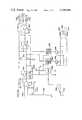
- FIGS. 3A and 3Btogether form a schematic diagram of the iris control circuit in accordance with the present invention.
- FIG. 1shows a closed circuit television camera 100 having a lens system 102 including a motor driven iris which receives signals on the conductors 104 to control the iris opening.
- the camera 100generates video signals on the conductor 106.
- the video signals on the conductor 106are passed to the black current compensating iris control circuit 108 which generates iris control signals on the conductors 104 to control the iris opening of the lens 102.
- FIG. 2illustrates an optically black filter 200 which prevents light from striking a selected portion of the camera tube face.
- the filteris formed on the face of the camera tube or incorporated into the faceplate of the tube; however, any light blocking arrangement is satisfactory in accordance with the present invention.
- the optically black filter 200permits a dark current sample to be taken by the iris control circuit 108.
- the basic theory of operation of the present inventionis to generate a dark current compensated video signal which can be used to control the iris opening of the lens 102 of a closed circuit television camera 100 to maintain the generation of an approximately constant amplitude video signal by the television camera.
- a portion of the light input to the television camerais blocked by the optically black filter 200 shown in FIG. 2 so that a dark current sample may be taken on horizontal scans of the camera 100 occurring behind the filter. For each field of video, a dark current sample is taken and maintained in a storage device during that field.
- the video signalis amplified and the horizontal and vertical blanking portions of the amplified video signal are replaced with the dark current sample to generate a dark current compensated or clamped video signal, i.e., the video signal superimposed on the dark current generated by the camera tube.
- the dark current sampleis then effectively subtracted from the dark current compensated video signal by means of a differential integrator.
- the difference between the two signalsis integrated to generate a signal representative of the magnitude of the video information signal generated by the camera 100.
- the integrated signalis passed to a first operational amplifier, the output of which is connected to a second operational amplifier.
- the motor which controls the iris of the lens 102is connected between the outputs of the first and second amplifiers.
- the first and second amplifiersare also connected to a reference potential and interconnected so that a positive change on the input of the first amplifier causes a positive change in its output signal and a negative change in the output signal of the second amplifier. Conversely, a negative change on the input of the first amplifier causes a negative change in its output and a positive change in the output of the second amplifier.
- the iris settingremains constant. If the video information signal decreases in amplitude, the output signal of the first operational amplifier increases and the output signal of the second operational amplifier decreases. These signals are applied to the motor which controls the iris of the lens 102 and are poled to open the iris thus admitting more light and increasing the magnitude of the video information signal to restore the system to equilibrium and remove the iris "move" signals from the outputs of the first and second operational amplifiers. Conversely, if the video information signal increases in amplitude, the output signal of the first operational amplifier decreases and the output signal of the second operational amplifier increases to close the iris of the lens 102 until equilibrium is once again restored.
- a switch which passes the integrated video information signal to the first operational amplifieris opened and the inputs to the first operational amplifier are controlled by manual iris open and close signals generated by the operator of the closed circuit television monitoring system.
- a by-pass circuitis connected around the open switch from the integrated video information signal to the input of the first operational amplifier to protect the camera tube.
- the lens irisis partially closed to prevent damage to the camera tube.
- FIGS. 3A and 3Btogether form a detailed schematic diagram of the dark current compensating iris control circuit 108 of FIG. 1.
- the video signal from the camera 100is received on the conductor 106 and amplified by operational amplifier 201 which is connected as a unity gain amplifier and serves as an impedance converting butter to isolate the video signal on the conductor 106 from the remainder of the iris control circuit.
- the capacitor 202 together with the switch 204 and light emitting diode (LED) 206form a clamp circuit which re-establishes the direct current (DC) level of the video signal.
- the switch 204is operated by the horizontal drive signal received on the conductor 207.
- the light emitting diode 206establishes a positive voltage of approximately 1.5 volts on the input to an operational amplifier 208 to insure that the operational amplifier 208 does not operate with ground potential on its input.
- the operational amplifier 208serves as a buffer to isolate the clamp circuit from the remainder of the iris control circuit.
- the output of the operational amplifier 208is the video input signal on the conductor 106 with a base DC level of approximately 1.5 volts.
- a dark current sampleis taken during each video field.
- the sampleis taken during the time that the silicon diode array is being scanned at a location behind the filter 200 of FIG. 2.
- the filter 200covers approximately the first 12 horizontal scan lines of the camera tube.
- a sample of the dark currentis obtained during the seventh horizontal scan of the silicon diode array.
- the sampleis taken by an eight-bit shift register 210 which is clocked by the horizontal drive signal received on conductor 207 and reset by the vertical drive signal received on conductor 211.
- the input signal to the shift register 210is held high so that a high signal or logical "one" is sequentially shifted into the individual stages of the shift register 210.
- the output signal of the eighth stage of the shift registeris inverted by a NAND gate 212 and combined with the output signal of the seventh stage of the shift register by a NAND gate 214.
- the output of the NAND gate 214is inverted by a NAND gate 216 to drive the sampling switch 218.
- the shift register 210is cleared by each vertical drive signal and the horizontal drive signals clock the shift register to shift a logical one sequentially into the eight stages. Once the shift register 210 is filled by the action of the first eight horizontal drive pulses, it remains full until cleared by the next vertical drive pulse.
- the arrival of the high signal at the seventh stage of the shift register 210activates or closes the switch 218 via the NAND gates 214, 216 and the arrival of the high signal at the output of the eighth stage of the shift register deactivates the switch 218 via the NAND gates 212, 214 and 216.
- the resistor 220 together with the capacitor 222form a sample and hold circuit with a large charging time constant so that intermittent overloads of the target surface will not appreciably change the charge on the capacitor 222.
- a Schottky diode 224 and resistor 226form a fast discharge network for the capacitor 222 for overloads which persist for a sufficient period of time to change the charge on the capacitor 222.
- a dark current compensated video signalis generated at the output of operational amplifier 228 by replacing the horizontal and vertical blanking portions of the video signal received from the operational amplifier 208 with the sampled dark current stored on the capacitor 222.
- Switches 230 and 232are driven by a combined blanking signal, i.e., the combination of the horizontal and vertical blanking signals, on the conductor 233 and the inverse of the combined blanking signal from the NAND gate 234, respectively.
- the operational amplifier 228receives the video signal from the operational amplifier 208 through the switch 232.
- the signal from the operational amplifier 208is interrupted by opening the switch 232 and the sampled dark current stored on the capacitor 222 is passed by a unity gain buffer amplifier 236 through the switch 230 to the input of the operational amplifier 228. Accordingly, the signal on the output of the operational amplifier 228 comprises the video signal information imposed on a DC voltage level which is equal to the dark current generated by the silicon diode array of the television camera tube.
- the dark current compensated video signal on the output of the operational amplifier 228is differentially integrated to control the iris of the lens 102 of the camera 100.
- the signal from the operational amplifier 228is passed via conductor 238 to the negative input of an operational amplifier 240, while the dark current signal on the output of the operational amplifier 236 is passed via conductor 241 to the positive input of the operational amplifier 240.
- the operational amplifier 240is connected as a differential integrator so that the signal on its output is effectively equal to the integrated value of the difference between the compensated video signal on the output of the operational amplifier 228 and the dark current signal on the output of the operational amplifier 236. Accordingly, the operational amplifier 240 generates a video level signal.
- the resistor network 242, connected to the positive input of the operational amplifier 240can be adjusted to set the video level maintained by the iris control circuit 108.
- the output signal of the operational amplifier 240is connected to the positive input of operational amplifier 246 through a switch 248. Since the compensated video signal from the operational amplifier 228 is received on the negative input of the operational amplifier 240, increases in the magnitude of the video signal produce decreases in the integrated output signal of the operational amplifier 240; and decreases in the magnitude of the video signal produce corresponding increases in the integrated output signal of the operational amplifier 240.
- the output of the operational amplifier 246is connected to the "open" terminal 247 of the motor 249 which controls the iris of the lens 102 and also to the negative input of an operational amplifier 250.
- the output of the operational amplifier 250is connected to the "close” terminal 251 of the motor 249 which controls the iris of the lens 102.
- the negative input of the operational amplifier 246 and the positive input of the operational amplifier 250are connected to a reference voltage generated by a resistance network 252.
- the motor 249opens the iris of the lens 102 if the open terminal 247 is positive relative to the close terminal 251 and closes the iris if the close terminal 251 is positive relative to the open terminal 247.
- the motor 249 controlling the irisis not activated and the iris setting does not change. If the video signal level increases resulting in a decrease in the integrated output of the operational amplifier 240, the output signal of the operational amplifier 246 is decreased which causes an increase in the output signal of the operational amplifier 250 to apply a voltage which operates the motor 249 to close the iris. The iris closes until the video signal amplitude is reduced to a point where the integrated output of the operational amplifier 240 is once again equal to the reference voltage applied to the operational amplifiers 246, 250 so that the iris setting is once again stable.
- the operational amplifier 246has an increase in output signal level
- the operational amplifier 250has a decrease in output signal level.
- This voltage polarityoperates the motor 249 to open the iris of the lens 102. The iris is opened until the video signal level increases to a point where the output of the operational amplifier 240 is once again equal to the reference voltage applied to the operational amplifiers 246, 250. In this manner, the iris setting of the lens 102 is automatically adjusted to maintain a magnitude of video signals determined by the setting of the resistance network 242.
- the iriscan also be controlled manually by operating switch 253 to apply a ground signal on auto/manual input terminal 254.
- the switch 248is opened and manual control switches 256, 258 are closed via switch 259.
- the opening of switch 248removes the output signal of the operational amplifier 240 from the positive input of the operational amplifier 246.
- the switch 248is shunted by a protection circuit comprising a series combination of a resistor 260, a diode 262 and a zener diode 264. This shunt path provides protection of the television camera tube while the iris control circuit is in the manual mode as will be described hereafter.
- the switches 256 and 258connect PNP transistors 266, 268 to the positive and negative inputs of the operational amplifier 246, respectively.
- a switch 270is provided to connect ground to either the "close” terminal 272 or the “open” terminal 274 to manually control the operation of the iris motor 249 to respectively close or open the iris of the lens 102.
- the switch 270is biased to return to a neutral position, as shown in FIG. 3, when not activated by the operator of the monitoring system utilizing the iris control circuit.
- the protection circuitcomprising the resistor 260, the diode 262 and the zener diode 264 protects the camera tube from damage in the event that an operator leaves the iris control circuit in the manual mode with the iris so fully opened that the incoming light may damage the tube. In that event, the protection circuit partially closes the iris if lighting conditions are such that the camera tube could be damaged.
- the integrated signal from the operational amplifier 240is coupled to the positive input of the operational amplifier 246 through the protection circuit. If the integrated output of the operational amplifier 240 exceeds the reference voltage by the sum of the zener voltage of the zener diode 264 and the forward voltage of the diode 262, the iris will be partially closed by the protection circuit coupling to the automatic portion of the iris control circuit. If the iris control circuit is then switched to the automatic mode by opening switch 253, the protection circuit is by-passed by the operation of the switch 248 and the iris is closed to the full extent provided by the automatic operation as previously described.
- circuit componentsWhile a large variety of circuit components are available and may be utilized in the illustrative embodiment of the present invention, typical commercially available devices are listed below for the major circuit elements.
Landscapes
- Engineering & Computer Science (AREA)
- Multimedia (AREA)
- Signal Processing (AREA)
- Closed-Circuit Television Systems (AREA)
- Diaphragms For Cameras (AREA)
Abstract
Description
______________________________________ Operational amplifiers CA3160, available from 201, 208, 228, 236 Radio Corporation of and 240 America Operational amplifiers μA759, available from 246 and 250 Fairchild Corporation Switches 204, 218, 230 MC14066B, available from 232, 248, 256, 258 Motorola Corporation and 259Shift Register 210 MC14015B, available from Motorola Corporation ______________________________________
Claims (6)
Priority Applications (2)
| Application Number | Priority Date | Filing Date | Title |
|---|---|---|---|
| US06/334,298US4399466A (en) | 1981-12-24 | 1981-12-24 | Dark current compensating lens iris control |
| CA000416619ACA1189956A (en) | 1981-12-24 | 1982-11-29 | Dark current compensating lens iris control |
Applications Claiming Priority (1)
| Application Number | Priority Date | Filing Date | Title |
|---|---|---|---|
| US06/334,298US4399466A (en) | 1981-12-24 | 1981-12-24 | Dark current compensating lens iris control |
Publications (1)
| Publication Number | Publication Date |
|---|---|
| US4399466Atrue US4399466A (en) | 1983-08-16 |
Family
ID=23306566
Family Applications (1)
| Application Number | Title | Priority Date | Filing Date |
|---|---|---|---|
| US06/334,298Expired - Fee RelatedUS4399466A (en) | 1981-12-24 | 1981-12-24 | Dark current compensating lens iris control |
Country Status (2)
| Country | Link |
|---|---|
| US (1) | US4399466A (en) |
| CA (1) | CA1189956A (en) |
Cited By (16)
| Publication number | Priority date | Publication date | Assignee | Title |
|---|---|---|---|---|
| US4516172A (en)* | 1981-08-10 | 1985-05-07 | Sony Corporation | Solid state television camera with iris control |
| US4562477A (en)* | 1983-09-26 | 1985-12-31 | Asahi Seimitsu Kabushiki Kaisha | Automatic diaphragm control device for use with CCTV camera |
| US4562476A (en)* | 1983-09-19 | 1985-12-31 | Asahi Seimitsu Kabushiki Kaisha | Automatic diaphragm control device for use IWT CCTV camera |
| US4599654A (en)* | 1984-10-31 | 1986-07-08 | Rca Corporation | Dark current eliminator useful for auto-iris controller |
| US4649431A (en)* | 1982-07-24 | 1987-03-10 | Asahi Kogaku Kogyo Kabushiki Kaisha | Video camera iris control circuit |
| US4660091A (en)* | 1985-09-16 | 1987-04-21 | Eastman Kodak Company | Exposure level correction for film-to-video conversion |
| US4675738A (en)* | 1984-09-17 | 1987-06-23 | Canon Kabushiki Kaisha | Image pickup device |
| US4682232A (en)* | 1984-10-11 | 1987-07-21 | Canon Kabushiki Kaisha | Capacitor coupled circuit |
| US4723170A (en)* | 1985-06-06 | 1988-02-02 | U.S. Philips Corporation | Camera for recording television, photographic or cinematographic images |
| US4808822A (en)* | 1984-04-16 | 1989-02-28 | The Secretary Of State For Defence In Her Britannic Majesty's Government Of The United Kingdom Of Great Britain And Northern Ireland | Thermal detector |
| US5057927A (en)* | 1988-08-31 | 1991-10-15 | Canon Kabushiki Kaisha | Image sensing apparatus |
| EP0424721A3 (en)* | 1989-10-24 | 1992-04-08 | Richard Wolf Gmbh | Automatic adjustment device for the light supply of an endoscope |
| US5148281A (en)* | 1990-03-24 | 1992-09-15 | Sony Corporation | Iris stabilizer for automatic video camera |
| US6489991B2 (en)* | 2000-01-26 | 2002-12-03 | Kowa Company Limited | TV camera system with external cable having built-in amplifier for connecting TV camera unit to lens unit |
| US20050078155A1 (en)* | 2003-10-14 | 2005-04-14 | Campion Kevin R. | Fluid delivery system for an ink jet print head |
| EP1841212A1 (en)* | 2006-03-30 | 2007-10-03 | Fujinon Corporation | Lens aperture-adjustment device and closed circuit television camera |
Citations (8)
| Publication number | Priority date | Publication date | Assignee | Title |
|---|---|---|---|---|
| US3180934A (en)* | 1962-08-24 | 1965-04-27 | Gen Precision Inc | Vidicon target voltage control system with dark current compensation |
| US3558809A (en)* | 1967-08-01 | 1971-01-26 | Sony Corp | Automatic dark current control system for pickup tubes employing a light inhibiting strip mounted on the pickup tube face plate |
| US3737571A (en)* | 1971-05-12 | 1973-06-05 | Gte Sylvania Inc | Automatic dark current control |
| US3814849A (en)* | 1972-10-13 | 1974-06-04 | Ball Brothers Res Corp | Leakage current compensating circuit for semiconductor image sensor |
| US4194220A (en)* | 1978-03-27 | 1980-03-18 | Ball Corporation | Leakage current compensating circuit for semiconductor image sensor |
| US4232331A (en)* | 1977-10-04 | 1980-11-04 | Victor Company Of Japan, Ltd. | Circuit for stabilizing the black level in an output signal of a camera tube in a color television camera |
| US4237407A (en)* | 1978-01-20 | 1980-12-02 | Victor Company Of Japan, Limited | Vertical deflection circuit for a camera tube in a television camera |
| US4291338A (en)* | 1980-04-29 | 1981-09-22 | The United States Of America As Represented By The Secretary Of The Navy | Automatic exposure control for pulsed active TV systems |
- 1981
- 1981-12-24USUS06/334,298patent/US4399466A/ennot_activeExpired - Fee Related
- 1982
- 1982-11-29CACA000416619Apatent/CA1189956A/ennot_activeExpired
Patent Citations (8)
| Publication number | Priority date | Publication date | Assignee | Title |
|---|---|---|---|---|
| US3180934A (en)* | 1962-08-24 | 1965-04-27 | Gen Precision Inc | Vidicon target voltage control system with dark current compensation |
| US3558809A (en)* | 1967-08-01 | 1971-01-26 | Sony Corp | Automatic dark current control system for pickup tubes employing a light inhibiting strip mounted on the pickup tube face plate |
| US3737571A (en)* | 1971-05-12 | 1973-06-05 | Gte Sylvania Inc | Automatic dark current control |
| US3814849A (en)* | 1972-10-13 | 1974-06-04 | Ball Brothers Res Corp | Leakage current compensating circuit for semiconductor image sensor |
| US4232331A (en)* | 1977-10-04 | 1980-11-04 | Victor Company Of Japan, Ltd. | Circuit for stabilizing the black level in an output signal of a camera tube in a color television camera |
| US4237407A (en)* | 1978-01-20 | 1980-12-02 | Victor Company Of Japan, Limited | Vertical deflection circuit for a camera tube in a television camera |
| US4194220A (en)* | 1978-03-27 | 1980-03-18 | Ball Corporation | Leakage current compensating circuit for semiconductor image sensor |
| US4291338A (en)* | 1980-04-29 | 1981-09-22 | The United States Of America As Represented By The Secretary Of The Navy | Automatic exposure control for pulsed active TV systems |
Cited By (20)
| Publication number | Priority date | Publication date | Assignee | Title |
|---|---|---|---|---|
| US4516172A (en)* | 1981-08-10 | 1985-05-07 | Sony Corporation | Solid state television camera with iris control |
| US4649431A (en)* | 1982-07-24 | 1987-03-10 | Asahi Kogaku Kogyo Kabushiki Kaisha | Video camera iris control circuit |
| US4562476A (en)* | 1983-09-19 | 1985-12-31 | Asahi Seimitsu Kabushiki Kaisha | Automatic diaphragm control device for use IWT CCTV camera |
| US4562477A (en)* | 1983-09-26 | 1985-12-31 | Asahi Seimitsu Kabushiki Kaisha | Automatic diaphragm control device for use with CCTV camera |
| US4808822A (en)* | 1984-04-16 | 1989-02-28 | The Secretary Of State For Defence In Her Britannic Majesty's Government Of The United Kingdom Of Great Britain And Northern Ireland | Thermal detector |
| US4675738A (en)* | 1984-09-17 | 1987-06-23 | Canon Kabushiki Kaisha | Image pickup device |
| US4682232A (en)* | 1984-10-11 | 1987-07-21 | Canon Kabushiki Kaisha | Capacitor coupled circuit |
| US4599654A (en)* | 1984-10-31 | 1986-07-08 | Rca Corporation | Dark current eliminator useful for auto-iris controller |
| US4723170A (en)* | 1985-06-06 | 1988-02-02 | U.S. Philips Corporation | Camera for recording television, photographic or cinematographic images |
| US4660091A (en)* | 1985-09-16 | 1987-04-21 | Eastman Kodak Company | Exposure level correction for film-to-video conversion |
| US5057927A (en)* | 1988-08-31 | 1991-10-15 | Canon Kabushiki Kaisha | Image sensing apparatus |
| EP0424721A3 (en)* | 1989-10-24 | 1992-04-08 | Richard Wolf Gmbh | Automatic adjustment device for the light supply of an endoscope |
| US5131381A (en)* | 1989-10-24 | 1992-07-21 | Richard Wolf Gmbh | Apparatus for automatically regulating the supply of light to an endoscope |
| US5148281A (en)* | 1990-03-24 | 1992-09-15 | Sony Corporation | Iris stabilizer for automatic video camera |
| US6489991B2 (en)* | 2000-01-26 | 2002-12-03 | Kowa Company Limited | TV camera system with external cable having built-in amplifier for connecting TV camera unit to lens unit |
| US20050078155A1 (en)* | 2003-10-14 | 2005-04-14 | Campion Kevin R. | Fluid delivery system for an ink jet print head |
| US6942324B2 (en) | 2003-10-14 | 2005-09-13 | Kevin R. Campion | Fluid delivery system for an ink jet print head |
| EP1841212A1 (en)* | 2006-03-30 | 2007-10-03 | Fujinon Corporation | Lens aperture-adjustment device and closed circuit television camera |
| US20070230942A1 (en)* | 2006-03-30 | 2007-10-04 | Fujinon Corporation | Lens aperture-adjustment device and closed circuit television camera |
| US7787760B2 (en) | 2006-03-30 | 2010-08-31 | Fujinon Corporation | Lens aperture-adjustment device and closed circuit television camera |
Also Published As
| Publication number | Publication date |
|---|---|
| CA1189956A (en) | 1985-07-02 |
Similar Documents
| Publication | Publication Date | Title |
|---|---|---|
| US4399466A (en) | Dark current compensating lens iris control | |
| US4678938A (en) | Solid-state image sensing apparatus having an automatic control loop | |
| JP3517614B2 (en) | Solid-state imaging device | |
| US7277130B2 (en) | Image pick-up device and camera system comprising an image pick-up device | |
| EP0053886B1 (en) | Television cameras | |
| US5157498A (en) | Image sensing device with non-linear converting means | |
| US8081250B2 (en) | Image pickup apparatus having a correction unit for correction of noise components generated by clamping circuits | |
| EP0476907A2 (en) | Solid-state imaging devices | |
| KR100574959B1 (en) | CMOS image sensor with automatic exposure control | |
| US20050195307A1 (en) | Image pickup apparatus including a plurailty of pixels, each having a photoelectric conversion element and an amplifier whose output is prevented from falling below a predetermined level | |
| JP2005536930A (en) | CMOS APS with stacked avalanche multiplication layer and low voltage readout electronics | |
| US7589769B2 (en) | Camera capable of canceling noise in image data and signal processing method thereof | |
| US4600946A (en) | Adaptive defect correction for solid-state imagers | |
| EP0067504B1 (en) | Apparatus for protecting an image pickup tube in a television camera | |
| US6963367B1 (en) | Image pickup apparatus | |
| US4503466A (en) | Apparatus and method for generating optimizing pictures under low light conditions | |
| US4409472A (en) | Iris servo apparatus | |
| US11356622B1 (en) | Single-ended capacitive trans-impedance amplifier (CTIA) unit cell for two-color applications | |
| KR20030036484A (en) | True Day Night Camera | |
| US5525922A (en) | Automatic gain and level control circuit and method | |
| US3781591A (en) | System for controlling the target voltage of image sensors | |
| EP0712236B1 (en) | Timing signal generator for a solid state imaging device having an electronic shutter | |
| JP2799072B2 (en) | Imaging device | |
| KR0165533B1 (en) | Imaging device | |
| US4190858A (en) | Method for improved performance of infrared vidicon cameras |
Legal Events
| Date | Code | Title | Description |
|---|---|---|---|
| AS | Assignment | Owner name:CALSPAN CORPORATION 4455 GENESSEE, BUFFALO, N.Y. 1 Free format text:ASSIGNMENT OF ASSIGNORS INTEREST.;ASSIGNOR:STEPHENSON, DONALD L.;REEL/FRAME:003971/0260 Effective date:19811222 | |
| AS | Assignment | Owner name:DIAMOND ELECTRONICS, INC., 4465 COON PATH ROAD, NO Free format text:ASSIGNMENT OF ASSIGNORS INTEREST.;ASSIGNOR:CALSPAN CORPORATION;REEL/FRAME:004593/0535 Effective date:19860728 Owner name:DIAMOND ELECTRONICS, INC., AN OH CORP Free format text:MERGER;ASSIGNORS:J. W. WOODLAND CORPORATION, AN UNQUALIFIED FL CORP. (MERGED INTO);ARVIN/DIAMOND, INC., AN OH CORP. (CHANGED TO);REEL/FRAME:004593/0542 Effective date:19860801 Owner name:DIAMOND ELECTRONICS, INC.,OHIO Free format text:ASSIGNMENT OF ASSIGNORS INTEREST;ASSIGNOR:CALSPAN CORPORATION;REEL/FRAME:004593/0535 Effective date:19860728 | |
| MAFP | Maintenance fee payment | Free format text:PAYMENT OF MAINTENANCE FEE, 4TH YEAR, PL 96-517 (ORIGINAL EVENT CODE: M170); ENTITY STATUS OF PATENT OWNER: LARGE ENTITY Year of fee payment:4 | |
| FEPP | Fee payment procedure | Free format text:MAINTENANCE FEE REMINDER MAILED (ORIGINAL EVENT CODE: REM.); ENTITY STATUS OF PATENT OWNER: LARGE ENTITY | |
| LAPS | Lapse for failure to pay maintenance fees | ||
| STCH | Information on status: patent discontinuation | Free format text:PATENT EXPIRED DUE TO NONPAYMENT OF MAINTENANCE FEES UNDER 37 CFR 1.362 | |
| FP | Lapsed due to failure to pay maintenance fee | Effective date:19910818 | |
| FEPP | Fee payment procedure | Free format text:PAYOR NUMBER ASSIGNED (ORIGINAL EVENT CODE: ASPN); ENTITY STATUS OF PATENT OWNER: LARGE ENTITY |