US4399099A - Optical fiber apparatus for quantitative analysis - Google Patents
Optical fiber apparatus for quantitative analysisDownload PDFInfo
- Publication number
- US4399099A US4399099AUS06/302,242US30224281AUS4399099AUS 4399099 AUS4399099 AUS 4399099AUS 30224281 AUS30224281 AUS 30224281AUS 4399099 AUS4399099 AUS 4399099A
- Authority
- US
- United States
- Prior art keywords
- fiber
- sheath
- energy
- analyte
- species
- Prior art date
- Legal status (The legal status is an assumption and is not a legal conclusion. Google has not performed a legal analysis and makes no representation as to the accuracy of the status listed.)
- Expired - Lifetime
Links
- 239000013307optical fiberSubstances0.000titleclaimsdescription14
- 238000004445quantitative analysisMethods0.000titleclaims9
- 239000012491analyteSubstances0.000claimsabstractdescription66
- 239000012530fluidSubstances0.000claimsabstractdescription43
- 238000006243chemical reactionMethods0.000claimsabstractdescription26
- 230000004048modificationEffects0.000claimsabstractdescription15
- 238000012986modificationMethods0.000claimsabstractdescription15
- 239000000126substanceSubstances0.000claimsabstractdescription11
- 239000000835fiberSubstances0.000claimsdescription68
- 239000003153chemical reaction reagentSubstances0.000claimsdescription27
- 239000000463materialSubstances0.000claimsdescription26
- 230000005855radiationEffects0.000claimsdescription26
- QVGXLLKOCUKJST-UHFFFAOYSA-Natomic oxygenChemical compound[O]QVGXLLKOCUKJST-UHFFFAOYSA-N0.000claimsdescription19
- 239000001301oxygenSubstances0.000claimsdescription19
- 229910052760oxygenInorganic materials0.000claimsdescription19
- 239000000975dyeSubstances0.000claimsdescription18
- 229920000642polymerPolymers0.000claimsdescription17
- 239000000427antigenSubstances0.000claimsdescription15
- 102000036639antigensHuman genes0.000claimsdescription14
- 108091007433antigensProteins0.000claimsdescription14
- 229940088598enzymeDrugs0.000claimsdescription14
- 239000007788liquidSubstances0.000claimsdescription14
- 108090000790EnzymesProteins0.000claimsdescription13
- 102000004190EnzymesHuman genes0.000claimsdescription13
- WQZGKKKJIJFFOK-GASJEMHNSA-NGlucoseNatural productsOC[C@H]1OC(O)[C@H](O)[C@@H](O)[C@@H]1OWQZGKKKJIJFFOK-GASJEMHNSA-N0.000claimsdescription13
- 239000008103glucoseSubstances0.000claimsdescription13
- 230000001186cumulative effectEffects0.000claimsdescription11
- 239000007850fluorescent dyeSubstances0.000claimsdescription11
- 230000005670electromagnetic radiationEffects0.000claimsdescription8
- 238000010521absorption reactionMethods0.000claimsdescription7
- 150000002605large moleculesChemical group0.000claimsdescription7
- 230000005540biological transmissionEffects0.000claimsdescription6
- GVEPBJHOBDJJJI-UHFFFAOYSA-NfluorantheneChemical groupC1=CC(C2=CC=CC=C22)=C3C2=CC=CC3=C1GVEPBJHOBDJJJI-UHFFFAOYSA-N0.000claimsdescription6
- 101710098119Chaperonin GroEL 2Proteins0.000claimsdescription5
- 108010015776Glucose oxidaseProteins0.000claimsdescription4
- 239000004366Glucose oxidaseSubstances0.000claimsdescription4
- 229940116332glucose oxidaseDrugs0.000claimsdescription4
- 235000019420glucose oxidaseNutrition0.000claimsdescription4
- 230000003287optical effectEffects0.000claimsdescription4
- 238000010791quenchingMethods0.000claimsdescription4
- 230000000171quenching effectEffects0.000claimsdescription3
- 150000003384small moleculesChemical class0.000claimsdescription3
- 229920001477hydrophilic polymerPolymers0.000claimsdescription2
- 150000001875compoundsChemical class0.000claims10
- 239000003054catalystSubstances0.000claims7
- 125000002791glucosyl groupChemical groupC1([C@H](O)[C@@H](O)[C@H](O)[C@H](O1)CO)*0.000claims2
- 238000000034methodMethods0.000abstractdescription26
- 238000004458analytical methodMethods0.000abstractdescription10
- 239000002904solventSubstances0.000description13
- 210000004369bloodAnatomy0.000description12
- 239000008280bloodSubstances0.000description12
- 239000000047productSubstances0.000description10
- 238000012360testing methodMethods0.000description10
- 238000003556assayMethods0.000description9
- 239000000356contaminantSubstances0.000description6
- 230000006870functionEffects0.000description6
- 238000009792diffusion processMethods0.000description5
- 208000015756familial Alzheimer diseaseDiseases0.000description5
- 235000019162flavin adenine dinucleotideNutrition0.000description5
- 229920002521macromoleculePolymers0.000description5
- 238000012544monitoring processMethods0.000description5
- 230000002441reversible effectEffects0.000description5
- 239000000243solutionSubstances0.000description5
- 210000001124body fluidAnatomy0.000description4
- 239000010839body fluidSubstances0.000description4
- 238000001311chemical methods and processMethods0.000description4
- 230000009977dual effectEffects0.000description4
- 238000005259measurementMethods0.000description4
- 230000035515penetrationEffects0.000description4
- -1polypropylenePolymers0.000description4
- 230000004044responseEffects0.000description4
- 230000035945sensitivityEffects0.000description4
- VYPSYNLAJGMNEJ-UHFFFAOYSA-Nsilicon dioxideInorganic materialsO=[Si]=OVYPSYNLAJGMNEJ-UHFFFAOYSA-N0.000description4
- XLYOFNOQVPJJNP-UHFFFAOYSA-NwaterSubstancesOXLYOFNOQVPJJNP-UHFFFAOYSA-N0.000description4
- MWUXSHHQAYIFBG-UHFFFAOYSA-NNitric oxideChemical compoundO=[N]MWUXSHHQAYIFBG-UHFFFAOYSA-N0.000description3
- 239000004743PolypropyleneSubstances0.000description3
- 239000003570airSubstances0.000description3
- 238000011088calibration curveMethods0.000description3
- 238000003018immunoassayMethods0.000description3
- 229920001155polypropylenePolymers0.000description3
- 239000002243precursorSubstances0.000description3
- 230000008569processEffects0.000description3
- 239000007787solidSubstances0.000description3
- 108010010803GelatinProteins0.000description2
- RAHZWNYVWXNFOC-UHFFFAOYSA-NSulphur dioxideChemical compoundO=S=ORAHZWNYVWXNFOC-UHFFFAOYSA-N0.000description2
- GWEVSGVZZGPLCZ-UHFFFAOYSA-NTitan oxideChemical compoundO=[Ti]=OGWEVSGVZZGPLCZ-UHFFFAOYSA-N0.000description2
- 239000012080ambient airSubstances0.000description2
- 210000001367arteryAnatomy0.000description2
- 239000013060biological fluidSubstances0.000description2
- 210000004027cellAnatomy0.000description2
- 230000008859changeEffects0.000description2
- HVYWMOMLDIMFJA-DPAQBDIFSA-NcholesterolChemical compoundC1C=C2C[C@@H](O)CC[C@]2(C)[C@@H]2[C@@H]1[C@@H]1CC[C@H]([C@H](C)CCCC(C)C)[C@@]1(C)CC2HVYWMOMLDIMFJA-DPAQBDIFSA-N0.000description2
- 238000010276constructionMethods0.000description2
- 230000000694effectsEffects0.000description2
- 239000005038ethylene vinyl acetateSubstances0.000description2
- 239000007789gasSubstances0.000description2
- 229920000159gelatinPolymers0.000description2
- 239000008273gelatinSubstances0.000description2
- 235000019322gelatineNutrition0.000description2
- 235000011852gelatine dessertsNutrition0.000description2
- 238000003780insertionMethods0.000description2
- 230000037431insertionEffects0.000description2
- 238000002844meltingMethods0.000description2
- 230000008018meltingEffects0.000description2
- 229920001200poly(ethylene-vinyl acetate)Polymers0.000description2
- 239000010453quartzSubstances0.000description2
- 238000009738saturatingMethods0.000description2
- 210000003462veinAnatomy0.000description2
- 102000009027AlbuminsHuman genes0.000description1
- 108010088751AlbuminsProteins0.000description1
- 208000028399Critical IllnessDiseases0.000description1
- 239000004593EpoxySubstances0.000description1
- 108090000371EsterasesProteins0.000description1
- 244000043261Hevea brasiliensisSpecies0.000description1
- 239000004677NylonSubstances0.000description1
- 229920012485Plasticized Polyvinyl chloridePolymers0.000description1
- 239000004698PolyethyleneSubstances0.000description1
- 239000004793PolystyreneSubstances0.000description1
- 239000004372Polyvinyl alcoholSubstances0.000description1
- 102000014961Protein PrecursorsHuman genes0.000description1
- 108010078762Protein PrecursorsProteins0.000description1
- 238000002835absorbanceMethods0.000description1
- 230000002378acidificating effectEffects0.000description1
- 230000009471actionEffects0.000description1
- 230000006978adaptationEffects0.000description1
- 230000003466anti-cipated effectEffects0.000description1
- 239000007864aqueous solutionSubstances0.000description1
- 239000003125aqueous solventSubstances0.000description1
- 230000002238attenuated effectEffects0.000description1
- 230000004888barrier functionEffects0.000description1
- 230000008901benefitEffects0.000description1
- 238000004166bioassayMethods0.000description1
- 230000015572biosynthetic processEffects0.000description1
- 229920005549butyl rubberPolymers0.000description1
- 235000012000cholesterolNutrition0.000description1
- 238000003776cleavage reactionMethods0.000description1
- 239000011248coating agentSubstances0.000description1
- 238000000576coating methodMethods0.000description1
- 229910052681coesiteInorganic materials0.000description1
- 238000012937correctionMethods0.000description1
- 229910052906cristobaliteInorganic materials0.000description1
- 230000001419dependent effectEffects0.000description1
- 238000007598dipping methodMethods0.000description1
- 238000009826distributionMethods0.000description1
- 231100000673dose–response relationshipToxicity0.000description1
- 238000005516engineering processMethods0.000description1
- 230000002255enzymatic effectEffects0.000description1
- 238000001952enzyme assayMethods0.000description1
- 238000011067equilibrationMethods0.000description1
- 210000003743erythrocyteAnatomy0.000description1
- 150000002148estersChemical class0.000description1
- 238000001125extrusionMethods0.000description1
- 238000001914filtrationMethods0.000description1
- 239000011521glassSubstances0.000description1
- 125000002887hydroxy groupChemical group[H]O*0.000description1
- 238000007654immersionMethods0.000description1
- 230000006872improvementEffects0.000description1
- 239000003295industrial effluentSubstances0.000description1
- 239000008235industrial waterSubstances0.000description1
- 238000001746injection mouldingMethods0.000description1
- 230000010354integrationEffects0.000description1
- 235000012054mealsNutrition0.000description1
- 239000012982microporous membraneSubstances0.000description1
- 238000000465mouldingMethods0.000description1
- 229920003052natural elastomerPolymers0.000description1
- 229920001194natural rubberPolymers0.000description1
- 229920001778nylonPolymers0.000description1
- 230000003647oxidationEffects0.000description1
- 238000007254oxidation reactionMethods0.000description1
- 239000002245particleSubstances0.000description1
- 230000035699permeabilityEffects0.000description1
- 239000012466permeateSubstances0.000description1
- ISWSIDIOOBJBQZ-UHFFFAOYSA-Nphenol groupChemical groupC1(=CC=CC=C1)OISWSIDIOOBJBQZ-UHFFFAOYSA-N0.000description1
- 229920003023plasticPolymers0.000description1
- 239000004033plasticSubstances0.000description1
- 229920003229poly(methyl methacrylate)Polymers0.000description1
- 239000004417polycarbonateSubstances0.000description1
- 229920000515polycarbonatePolymers0.000description1
- 229920000573polyethylenePolymers0.000description1
- 229920001195polyisoprenePolymers0.000description1
- 229920005594polymer fiberPolymers0.000description1
- 239000004926polymethyl methacrylateSubstances0.000description1
- 229920002223polystyrenePolymers0.000description1
- 229920002635polyurethanePolymers0.000description1
- 239000004814polyurethaneSubstances0.000description1
- 229920002451polyvinyl alcoholPolymers0.000description1
- 239000004800polyvinyl chlorideSubstances0.000description1
- 229920000915polyvinyl chloridePolymers0.000description1
- 238000003672processing methodMethods0.000description1
- 239000011253protective coatingSubstances0.000description1
- 238000003127radioimmunoassayMethods0.000description1
- 239000000376reactantSubstances0.000description1
- 230000007017scissionEffects0.000description1
- 238000000926separation methodMethods0.000description1
- 239000000377silicon dioxideSubstances0.000description1
- 229920002379silicone rubberPolymers0.000description1
- 239000004945silicone rubberSubstances0.000description1
- 230000007480spreadingEffects0.000description1
- 238000003892spreadingMethods0.000description1
- 238000010561standard procedureMethods0.000description1
- 230000003068static effectEffects0.000description1
- 229910052682stishoviteInorganic materials0.000description1
- 238000003860storageMethods0.000description1
- 238000003786synthesis reactionMethods0.000description1
- 229920001169thermoplasticPolymers0.000description1
- 238000001721transfer mouldingMethods0.000description1
- 230000001052transient effectEffects0.000description1
- 229910052905tridymiteInorganic materials0.000description1
- 238000011144upstream manufacturingMethods0.000description1
- 238000001429visible spectrumMethods0.000description1
- 230000000007visual effectEffects0.000description1
- 238000009736wettingMethods0.000description1
Images


Classifications
- G—PHYSICS
- G01—MEASURING; TESTING
- G01N—INVESTIGATING OR ANALYSING MATERIALS BY DETERMINING THEIR CHEMICAL OR PHYSICAL PROPERTIES
- G01N21/00—Investigating or analysing materials by the use of optical means, i.e. using sub-millimetre waves, infrared, visible or ultraviolet light
- G01N21/62—Systems in which the material investigated is excited whereby it emits light or causes a change in wavelength of the incident light
- G01N21/63—Systems in which the material investigated is excited whereby it emits light or causes a change in wavelength of the incident light optically excited
- G01N21/64—Fluorescence; Phosphorescence
- G01N21/6428—Measuring fluorescence of fluorescent products of reactions or of fluorochrome labelled reactive substances, e.g. measuring quenching effects, using measuring "optrodes"
- G01N21/643—Measuring fluorescence of fluorescent products of reactions or of fluorochrome labelled reactive substances, e.g. measuring quenching effects, using measuring "optrodes" non-biological material
- A—HUMAN NECESSITIES
- A61—MEDICAL OR VETERINARY SCIENCE; HYGIENE
- A61B—DIAGNOSIS; SURGERY; IDENTIFICATION
- A61B5/00—Measuring for diagnostic purposes; Identification of persons
- A61B5/145—Measuring characteristics of blood in vivo, e.g. gas concentration or pH-value ; Measuring characteristics of body fluids or tissues, e.g. interstitial fluid or cerebral tissue
- A61B5/1455—Measuring characteristics of blood in vivo, e.g. gas concentration or pH-value ; Measuring characteristics of body fluids or tissues, e.g. interstitial fluid or cerebral tissue using optical sensors, e.g. spectral photometrical oximeters
- A61B5/1459—Measuring characteristics of blood in vivo, e.g. gas concentration or pH-value ; Measuring characteristics of body fluids or tissues, e.g. interstitial fluid or cerebral tissue using optical sensors, e.g. spectral photometrical oximeters invasive, e.g. introduced into the body by a catheter
- C—CHEMISTRY; METALLURGY
- C12—BIOCHEMISTRY; BEER; SPIRITS; WINE; VINEGAR; MICROBIOLOGY; ENZYMOLOGY; MUTATION OR GENETIC ENGINEERING
- C12Q—MEASURING OR TESTING PROCESSES INVOLVING ENZYMES, NUCLEIC ACIDS OR MICROORGANISMS; COMPOSITIONS OR TEST PAPERS THEREFOR; PROCESSES OF PREPARING SUCH COMPOSITIONS; CONDITION-RESPONSIVE CONTROL IN MICROBIOLOGICAL OR ENZYMOLOGICAL PROCESSES
- C12Q1/00—Measuring or testing processes involving enzymes, nucleic acids or microorganisms; Compositions therefor; Processes of preparing such compositions
- G—PHYSICS
- G01—MEASURING; TESTING
- G01N—INVESTIGATING OR ANALYSING MATERIALS BY DETERMINING THEIR CHEMICAL OR PHYSICAL PROPERTIES
- G01N21/00—Investigating or analysing materials by the use of optical means, i.e. using sub-millimetre waves, infrared, visible or ultraviolet light
- G01N21/75—Systems in which material is subjected to a chemical reaction, the progress or the result of the reaction being investigated
- G01N21/77—Systems in which material is subjected to a chemical reaction, the progress or the result of the reaction being investigated by observing the effect on a chemical indicator
- G01N21/7703—Systems in which material is subjected to a chemical reaction, the progress or the result of the reaction being investigated by observing the effect on a chemical indicator using reagent-clad optical fibres or optical waveguides
- G—PHYSICS
- G01—MEASURING; TESTING
- G01N—INVESTIGATING OR ANALYSING MATERIALS BY DETERMINING THEIR CHEMICAL OR PHYSICAL PROPERTIES
- G01N33/00—Investigating or analysing materials by specific methods not covered by groups G01N1/00 - G01N31/00
- G01N33/48—Biological material, e.g. blood, urine; Haemocytometers
- G01N33/50—Chemical analysis of biological material, e.g. blood, urine; Testing involving biospecific ligand binding methods; Immunological testing
- G01N33/52—Use of compounds or compositions for colorimetric, spectrophotometric or fluorometric investigation, e.g. use of reagent paper and including single- and multilayer analytical elements
- G01N33/525—Multi-layer analytical elements
- G—PHYSICS
- G01—MEASURING; TESTING
- G01N—INVESTIGATING OR ANALYSING MATERIALS BY DETERMINING THEIR CHEMICAL OR PHYSICAL PROPERTIES
- G01N33/00—Investigating or analysing materials by specific methods not covered by groups G01N1/00 - G01N31/00
- G01N33/48—Biological material, e.g. blood, urine; Haemocytometers
- G01N33/50—Chemical analysis of biological material, e.g. blood, urine; Testing involving biospecific ligand binding methods; Immunological testing
- G01N33/53—Immunoassay; Biospecific binding assay; Materials therefor
- G01N33/5302—Apparatus specially adapted for immunological test procedures
- G—PHYSICS
- G01—MEASURING; TESTING
- G01N—INVESTIGATING OR ANALYSING MATERIALS BY DETERMINING THEIR CHEMICAL OR PHYSICAL PROPERTIES
- G01N21/00—Investigating or analysing materials by the use of optical means, i.e. using sub-millimetre waves, infrared, visible or ultraviolet light
- G01N21/17—Systems in which incident light is modified in accordance with the properties of the material investigated
- G01N21/41—Refractivity; Phase-affecting properties, e.g. optical path length
- G01N2021/4166—Methods effecting a waveguide mode enhancement through the property being measured
- G—PHYSICS
- G01—MEASURING; TESTING
- G01N—INVESTIGATING OR ANALYSING MATERIALS BY DETERMINING THEIR CHEMICAL OR PHYSICAL PROPERTIES
- G01N21/00—Investigating or analysing materials by the use of optical means, i.e. using sub-millimetre waves, infrared, visible or ultraviolet light
- G01N21/62—Systems in which the material investigated is excited whereby it emits light or causes a change in wavelength of the incident light
- G01N21/63—Systems in which the material investigated is excited whereby it emits light or causes a change in wavelength of the incident light optically excited
- G01N21/64—Fluorescence; Phosphorescence
- G01N21/6428—Measuring fluorescence of fluorescent products of reactions or of fluorochrome labelled reactive substances, e.g. measuring quenching effects, using measuring "optrodes"
- G01N2021/6432—Quenching
- G—PHYSICS
- G01—MEASURING; TESTING
- G01N—INVESTIGATING OR ANALYSING MATERIALS BY DETERMINING THEIR CHEMICAL OR PHYSICAL PROPERTIES
- G01N21/00—Investigating or analysing materials by the use of optical means, i.e. using sub-millimetre waves, infrared, visible or ultraviolet light
- G01N21/75—Systems in which material is subjected to a chemical reaction, the progress or the result of the reaction being investigated
- G01N21/77—Systems in which material is subjected to a chemical reaction, the progress or the result of the reaction being investigated by observing the effect on a chemical indicator
- G01N21/7703—Systems in which material is subjected to a chemical reaction, the progress or the result of the reaction being investigated by observing the effect on a chemical indicator using reagent-clad optical fibres or optical waveguides
- G01N2021/7706—Reagent provision
- G01N2021/7709—Distributed reagent, e.g. over length of guide
- G01N2021/7716—Distributed reagent, e.g. over length of guide in cladding
- G—PHYSICS
- G01—MEASURING; TESTING
- G01N—INVESTIGATING OR ANALYSING MATERIALS BY DETERMINING THEIR CHEMICAL OR PHYSICAL PROPERTIES
- G01N21/00—Investigating or analysing materials by the use of optical means, i.e. using sub-millimetre waves, infrared, visible or ultraviolet light
- G01N21/75—Systems in which material is subjected to a chemical reaction, the progress or the result of the reaction being investigated
- G01N21/77—Systems in which material is subjected to a chemical reaction, the progress or the result of the reaction being investigated by observing the effect on a chemical indicator
- G01N21/7703—Systems in which material is subjected to a chemical reaction, the progress or the result of the reaction being investigated by observing the effect on a chemical indicator using reagent-clad optical fibres or optical waveguides
- G01N2021/7706—Reagent provision
- G01N2021/773—Porous polymer jacket; Polymer matrix with indicator
- G—PHYSICS
- G01—MEASURING; TESTING
- G01N—INVESTIGATING OR ANALYSING MATERIALS BY DETERMINING THEIR CHEMICAL OR PHYSICAL PROPERTIES
- G01N21/00—Investigating or analysing materials by the use of optical means, i.e. using sub-millimetre waves, infrared, visible or ultraviolet light
- G01N21/75—Systems in which material is subjected to a chemical reaction, the progress or the result of the reaction being investigated
- G01N21/77—Systems in which material is subjected to a chemical reaction, the progress or the result of the reaction being investigated by observing the effect on a chemical indicator
- G01N2021/7769—Measurement method of reaction-produced change in sensor
- G01N2021/7786—Fluorescence
- Y—GENERAL TAGGING OF NEW TECHNOLOGICAL DEVELOPMENTS; GENERAL TAGGING OF CROSS-SECTIONAL TECHNOLOGIES SPANNING OVER SEVERAL SECTIONS OF THE IPC; TECHNICAL SUBJECTS COVERED BY FORMER USPC CROSS-REFERENCE ART COLLECTIONS [XRACs] AND DIGESTS
- Y10—TECHNICAL SUBJECTS COVERED BY FORMER USPC
- Y10S—TECHNICAL SUBJECTS COVERED BY FORMER USPC CROSS-REFERENCE ART COLLECTIONS [XRACs] AND DIGESTS
- Y10S435/00—Chemistry: molecular biology and microbiology
- Y10S435/968—High energy substrates, e.g. fluorescent, chemiluminescent, radioactive
- Y—GENERAL TAGGING OF NEW TECHNOLOGICAL DEVELOPMENTS; GENERAL TAGGING OF CROSS-SECTIONAL TECHNOLOGIES SPANNING OVER SEVERAL SECTIONS OF THE IPC; TECHNICAL SUBJECTS COVERED BY FORMER USPC CROSS-REFERENCE ART COLLECTIONS [XRACs] AND DIGESTS
- Y10—TECHNICAL SUBJECTS COVERED BY FORMER USPC
- Y10S—TECHNICAL SUBJECTS COVERED BY FORMER USPC CROSS-REFERENCE ART COLLECTIONS [XRACs] AND DIGESTS
- Y10S436/00—Chemistry: analytical and immunological testing
- Y10S436/805—Optical property
- Y—GENERAL TAGGING OF NEW TECHNOLOGICAL DEVELOPMENTS; GENERAL TAGGING OF CROSS-SECTIONAL TECHNOLOGIES SPANNING OVER SEVERAL SECTIONS OF THE IPC; TECHNICAL SUBJECTS COVERED BY FORMER USPC CROSS-REFERENCE ART COLLECTIONS [XRACs] AND DIGESTS
- Y10—TECHNICAL SUBJECTS COVERED BY FORMER USPC
- Y10S—TECHNICAL SUBJECTS COVERED BY FORMER USPC CROSS-REFERENCE ART COLLECTIONS [XRACs] AND DIGESTS
- Y10S436/00—Chemistry: analytical and immunological testing
- Y10S436/807—Apparatus included in process claim, e.g. physical support structures
- Y—GENERAL TAGGING OF NEW TECHNOLOGICAL DEVELOPMENTS; GENERAL TAGGING OF CROSS-SECTIONAL TECHNOLOGIES SPANNING OVER SEVERAL SECTIONS OF THE IPC; TECHNICAL SUBJECTS COVERED BY FORMER USPC CROSS-REFERENCE ART COLLECTIONS [XRACs] AND DIGESTS
- Y10—TECHNICAL SUBJECTS COVERED BY FORMER USPC
- Y10T—TECHNICAL SUBJECTS COVERED BY FORMER US CLASSIFICATION
- Y10T436/00—Chemistry: analytical and immunological testing
- Y10T436/20—Oxygen containing
- Y10T436/207497—Molecular oxygen
- Y10T436/209163—Dissolved or trace oxygen or oxygen content of a sealed environment
Definitions
- Dry chemical techniquesutilize reagents stored under dry conditions within a single or multi-layer flat element such that a test liquid will result in a reaction that can be radiometrically detected (see U.S. Pat. No. 3,092,465). These techniques are simple to use, but have traditionally yielded only qualitative results. There are several reasons for this that have been well explained in recent U.S. patents assigned to Eastman Kodak (see U.S. Pat. Nos. 3,992,158, 4,042,335 and 4,066,403). The major reasons are: non-uniform spreading of the fluid over the flat surface; non-uniform penetration of the fluid or analyte into the region where the reagent is stored; and non-uniform effects at the edges of the spread liquid.
- the Kodak techniqueutilizes flat, multilayered sheets arranged in sequence such that the top layer receives the liquid sample and it passes downward undergoing separations and reactions in a pre-arranged sequence.
- the sheetis designed to accept a small volume of liquid and distribute it uniformly over a reproducible area; the area is less than the total area of the multi-laminar sheet.
- Each layer of the sheetis essentially homogeneous in a direction parallel to the surface; thus, once spread radially (a rapid process) the components of the liquid can move downward at rates that are essentially the same in any plane that is parallel to the surface. In this way uniform reactions, filtrations, etc. can occur.
- the analyteis detected in such multilayered sheets by radiometric methods, carried out in a thermostatted environment. This permits one to use kinetic measurements as well as static ones in order to detect analyte concentrations in the liquid sample.
- Radiationis caused to enter this assembly in a path which is transverse to the several layers.
- the radiationis modified by the analyte or by a component or product of the analyte.
- the exciting radiationmay be partially absorbed by the analyte or by a component or product of the analyte.
- the modified radiationmay be reflected back transversely through the laminar assembly or it may pass through the entire assembly.
- the path of the exciting radiationis very short and is determined by the thickness of the layer in which the exciting radiation encounters the substance which is excited. Since this dimension must be very small to permit rapid measurement, e.g., 10 ⁇ m to 100 ⁇ m the degree of modification of the exciting radiation is quite small.
- a corewhich is transmissive to the chosen energy, which may be electromagnetic (e.g. ultraviolet or visible light), electronic or sonic energy.
- This coreis provided with one or more permeable or semi-permeable sheaths (i.e. permeable to a fluid sample containing the analyte, or permeable to so much of the test fluid as is desired but acting to filter out unwanted components).
- This part of the apparatusmay be referred to as the "sheath structure" signifying that it may consist of one or more permeable or semi-permeable sheaths.
- sheath structuresignifying that it may consist of one or more permeable or semi-permeable sheaths.
- the coretransmissive to the chosen energy and causes that energy to pass in a direction generally parallel to the surface to which the test fluid is applied.
- the corehas an "active length" which, as will appear more fully hereinafter, is that portion of its length, usually but not necessarily less than the entire length of the core, wherein the energy passing through the core is subjected to the influence of the test fluid and is modified thereby.
- the magnitude of this active lengthis large, and as will appear more fully hereinafter it is very large compared to the thickness of the sheath structure and/or the core.
- the coreif permeable to an analyte in a liquid or gaseous test fluid, or to a product of such analyte, may be bare, i.e. devoid of a sheath structure and may therefore be in direct contact with the test fluid.
- the physical shape and configuration of the device or apparatus of the inventionmay vary considerably.
- the deviceis cylindrical and consists of a central core or fiber which is transparent to the exciting radiation and is surrounded by a sheath structure consisting of one or more concentric layers of absorptive material.
- the shape in cross sectionmay be polygonal with one or more absorptive layers surrounding the transissive layer.
- the path of the carrier energyis generally parallel to, rather than transverse to the overlying layer or layers.
- the carrier energywill be described as electromagnetic radiation.
- FIGS. 1 to 4depict an embodiment of the invention wherein a single inner core-outer sheath configuration is used.
- FIGS. 5 and 6show typical curves of the relationship of the output of electrical energy produced from the emitted light energy and the analyte concentrations.
- FIG. 7depicts an embodiment of the invention wherein two parallel fiber assay devices (FAD) are used.
- FIG. 8depicts a range limitation of highly sensitive assay systems.
- FIG. 9depicts a multiple fiber assay device (MFAD) configuration of the invention.
- FIGS. 10 to 12depict a dual FAD designed for glucose determinations.
- FIGS. 13 and 14depict a continuous monitoring case for the use of a dual FAD.
- FIGS. 15 and 16depict a multi-sheathed single FAD of a multiple FAD system.
- FIGS. 17 and 18depict an embodiment of the invention designed for high sensitivity immunoassays.
- FIG. 19depicts a single sheath-inner core embodiment wherein the sheath has a lower refractive index than the core.
- FIG. 20depicts a wicking means for uniformly saturating a FAD.
- FIG. 21depicts a device of the invention designed for enzyme determinations in fluid samples.
- FIGS. 22 and 23depict embodiments of the invention wherein the fiber is incorporated into a catheter structure.
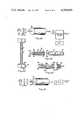
- FIG. 1there is shown one form of the apparatus of the present invention which is generally designated by the reference numeral 10 and which, as shown in the cross sectional view of FIG. 2, consists of an inner core of fiber 11 and an outer sheath 12.
- the core or fiber 11is transparent to the exciting radiation but, instead of being a conventional optical fiber such as quartz fiber, it is selected so that it is not only optically transmissive but is also permeable to components of an aqueous solution.
- the outer sheath 12is of absorptive, semi-permeable material.
- a fluid containing the analyte under considerationfor example blood where it is desired to measure one of its low molecular weight components.
- the material of which the sheath 12 is constructedmay be suitably selected so as to filter out such large molecules and elements.
- an outer layer(not shown) may be provided which is permeable to water, and small molecules but which is impermeable to large molecules and formed elements of the blood.
- one function of layer 12is to act as an impermeable barrier to those unwanted components of the test fluid.
- the fluidWhen the device 10 is immersed in the test fluid, for example, in blood, the fluid will penetrate to the core of fiber 11. Its presence may be detected by illuminating the core with (e.g.) light of a wavelength that is selectively absorbed by the analyte. Thus the diminution of light that emerges from the exit end of the fiber is proportional to the concentration of the analyte in the sample fluid.
- FIG. 1there is shown diagramatically a system for carrying out such a determination of analyte in an aqueous solvent, including a source of radiation 13, a focussing lens 14 and a suitable filter 15 to transmit light of the proper wavelength.
- a source of radiation 13At the exit end of the device is a light detector 16 and an electrical signal processor 17.
- the electrical signal processoramplifies the signal from the light detector and may be made from any of several well known and commercially available devices, and may include readout means of visual type and a recorder for a printed readout.
- the instruments of FIG. 1that are used to introduce energy into the analytical apparatus and to measure that which leaves the system can be configured in any of a number of ways depending on the use of the device.
- the simplicity of use and intrinsically rapid response of the inventionsuggests that one use will be to make bedside measurements. In such a case a portable unit with rechargeable batteries would be preferred.
- modern electronic data processing methodsare so compact that one may further simplify the use of the analytical apparatus by utilizing electronic corrections and calibrations which permit the use of assay methods that are non-linear in their response to the analyte concentration. In fact, it is possible to assemble several analytical elements in a parallel arrangement in a single instrument.
- the letters "a” and “b” and the lead lines therefrom in FIG. 1signify the "active length" of energy transmissive device 10.
- This active lengthis that portion of the device which is exposed to analyte, or to a product of an analyte, and along which the flow of energy is cumulatively modified by the analyte or a product of the analyte.
- the path from "a” to "b”(which may be continuous or segmented, is long compared to the thickness of the element 10.
- the core 11may be bare, i.e. devoid of a sheath.
- an industrial fluid or a biological fluidcontains the analyte of interest, e.g. a contaminant such as sulfur dioxide or a nitrogen oxide in stack gas or a phenolic contaminant
- the material of the core 11may be selected so that it absorbs such contaminant which modifies the flow of energy through the core, e.g. by absorption of a selected wavelength of light.
- FIG. 3a system similar to that of FIG. 1 is shown where the fiber assay device (FAD) 10 shown on a larger and exaggerated scale and with the interior exposed to show the several components including a core 25 (hereinafter designated by the letter "C") which is transmissive to ultraviolet radiation and is impermeable to fluids; and a sheath 26 of gas permeable material containing an oxygen quenchable fluorescent dye substance.
- the index of refraction n s of sheath 26is greater than the index of refraction n c of the core.
- the outer sheath 27is oxygen permeable and is reflective. It may be impermeable to large molecules and to formed elements such as platelets and red cells in blood.
- FIG. 4which is a fragmentary cross section through the FAD, molecules of fluorescent dye are indicated at 28.
- Ultraviolet lightpasses through the core and some of it is refracted into the sheath 26 where it reacts with fluorescent molecules which emit radiation in the visible spectrum; such emission is isotropic. That visible radiation which impinges upon the interface between the sheaths 26 and 27 is reflected into the core along with radiation which enters the core directly.
- ⁇ iwill not, of course, be constant inasmuch as the UV radiation is somewhat attenuated as it passes through the core 25. Nevertheless a cumulative effect will occur and the intensity of emitted visible light ##EQU1## will be much greater than the value of ⁇ i emerging from a small segment of the path.
- a fluidfor example blood, industrial water or river water containing oxygen (which is the analyte to be determined)
- oxygenwhich is the analyte to be determined
- the dissolved oxygen in the fluidwill quench fluorescence, therefore, it will diminish the intensity of flourescent light emitted at the output end of the core.
- the emitted radiationpasses through the ultraviolet filter 18, then through an opto-electrical detector (O-E.D.) 30 which acts as a transducer to convert the emitted light energy into electrical energy.
- O-E.D.opto-electrical detector
- a suitable processorconsists of amplifiers, limiters, meters, and elements for electrical logic, as are well known to those in the instrumentation business.
- a molecule well known for its tendency to exhibit O 2 quenching of fluorescenceis fluoranthrene.
- FIG. 5shows a curve typical of such an output.
- Advantageous features of this systeminclude its low temperature sensitivity, and rapid response time.
- FIG. 6a plot of analyte concentration against output of a similar system is shown.
- the solid curverepresents a mean calibration curve in the absence of other molecules.
- the dotted curveis the calibration curve in the presence of a molecule that may also occur in the fluid.
- the calibration curveshifts up or down the vertical axis as a function of the unknown concentration of contaminant, C c . If C A is the concentration of the analyte, we may represent this phenomeon of interference by the expression:
- ⁇represents a proportionality.
- DFAdouble fiber assay
- FIG. 8Yet another limitation of many highly sensitive assay systems (e.g. radioimmuno assay) is summarized in FIG. 8.
- the analyteis detected by reaction with a reagent.
- the high specificity of the reactionleads to a steep dose response curve; i.e. for a given reagent concentration the output changes over its full range when traversing a narrow range of analyte concentration.
- the range of anticipated analyte concentrationis wide, as denoted by the shaded area in FIG. 7, one must perform several determinations, each with a different reactant concentration in order to determine the analyte concentration.
- a multiple fiber assay deviceconsisting on n such FAD devices, each of which embodies within one of its sheaths a reagent.
- the reagent concentrationsvary from one device to the other. It will be apparent that when these fibers are wet by a fluid that there is one reagent concentration resulting in an output which is a reflection of the analyte concentration. The other fibers either over- or under-react with the analyte yielding unmeasurable outputs.
- FAD jbeing an integer from one to n
- the separate outputs of the FADsare converted by O-E.D.s to electrical outputs which are separately transmitted to a switching device 36 controlled by a microprocessor 37 to select the output of FAD j and reject the others.
- sheath 26 of each devicecontains an oxygen quenchable dye and sheath 27 is an oxygen permeable sheath which reflects light back into the core.
- the sheath 27also functions to prevent penetration of fluorescent molecules from the sample.
- an outermost sheath(not shown) may be employed for that purpose.
- One such device 36ais the control device that measures oxygen (the contaminant); and the other 36b is modified by having in the sheath 27 a quantity of glucose oxidase. Both devices are wetted with a sample simultaneously.
- glucose oxidase in sheath 26 of device 36bcauses reaction of a portion of the oxygen with the glucose and therefore diminishes the oxygen available for quenching fluorescence.
- the rate of oxidationis proportional to the concentration of glucose. Therefore, the output of the device 36b will be greater than that of the device 36a and the difference is measured by the output of the device.
- the systemincludes a filter 37, OED devices 38 and a processor 39.
- FIG. 11the output of each O-ED in FIG. 10 is plotted as a function of time following addition of a blood sample to the DFAD, presuming that the oxygen level of the blood is higher than that of ambient air.
- the oxygen sensor 36athe excess oxygen is lost by diffusion to the air and ultimately the output (dotted) curve reaches a steady value of fluorescence that reflects equilibration with air.
- the modified fiber 36bconsumes the oxygen more rapidly due to its reaction with the glucose in the sample, causing a greater rise in fluorescence. When all the glucose that is present in the blood has been consumed, this fiber also equilibrates with ambient air. Thus, the two curves ultimately merge.
- FIG. 12is a curve representing the integration of the space between the two curves and therefore its area is a measure of the total amount of glucose in the sample.
- FIG. 13a plot is shown in the case of continuous monitoring where the dual FAD device is implanted within a patient.
- the first portion of the curverepresents normal variations in glucose level in the blood and the large increase represents a large increase in glucose level after, for example, a patient has had a meal.
- the solid curverepresents the output of device 36b and the broken line curve represents the output of device 36a.
- FIG. 14is a plot of the difference between the curves of FIG. 13, therefore of the variation with time of the glucose level of the patient.
- the FADcomprises an innermost sheath 41 whose index of refraction n s is greater than the index of refraction n c of the core and which contains an antigen-flourescein complex designated as A* in quantity sufficient to fully saturate an antibody located in sheath 43.
- Sheath 42is a sheath which is hydrophilic and contains reflective particles and which is impermeable to antigen (A) when dry but permeable when wet.
- Sheath 43is hydrophilic and contains as a reagent, an antibody Ab to the antigens A* and A. (A is the analyte of interest.)
- the outermost sheath 44is microporous. A sample of fluid containing the antigen A is added to sheath 44.
- Adiffuses through sheath 44 into sheath 43 and A* diffuses through sheath 42 into sheath 43. The following competing reversible reactions occur in sheath 43.
- reaction (1)will proceed to a state of equilibrium at which time the rate of diffusion of A* out of sheath 41 will equal the rate of diffusion of A* back into sheath 41. At that time the output will become constant, as shown by the lower curve in FIG. 16. Virtually all of A* is bound to Ab, yielding a low level of fluorescence.
- the middle curverepresents the case when the sample contains a finite quantity of A; and the upper curve represents the case where A>>A* so that very little Ab-A* is formed.
- the spacing of the curves in FIG. 16is arbitrary. It will be apparent that in actuality this spacing will depend upon the concentration of A* in sheath 41 and the concentration of A in the sample.
- concentration of A* in sheath 41By employing a bundle of FADs each containing a different concentration of A* in sheath 41, one of the devices will contain an optimum concentration of A* such that the spacing of the curves is optimum.
- the logic selector 45the output of that device will be selected and the others rejected.
- concentration of A in the samplemay be determined.
- FIG. 17illustrates in detail a single element of an array of several FADs, each containing different concentrations of antibody Ab.
- the core cis permeable to the product Y of a reaction ##EQU2## wherein E is an enzyme, X is high molecular weight and Y is low molecular weight.
- Sheath 50is permeable to Y but not to X; sheath 51 contains an antibody Ab and an antigen-enzyme complex A-E wherein the enzyme E is active. This complex reacts with antibody in accordance with the following reversible reaction.
- Enzyme Eis inactive in A-E-Ab.
- Sheath 50has a lower index of refraction than the index of refraction of core c, in order to reflect all the light along the axial path within the core.
- This systemis intended to measure analyte A, which is an antigen, in a fluid sample.
- Sheath 51is microporous and permeable to A. When sheath 51 is wetted with a sample containing the antigen A, it diffuses into sheath 51 but no further. There it reacts with Ab, displacing A-E in direct proportion to their relative concentrations. The A-E that is released catalyzes the reaction, forming Y which then diffuses into the core where it is detected by light that is transmitted along the core. If the wavelength of light is selected for maximum absorbance by Y and sheath 51 contains an excess of X the method will be highly sensitive and specific for the presence of A in the sample fluid.
- an FADcomprising a core c and a sheath 52 having a lower refractive index than the core or containing reflective material (or surrounded by a reflective sheath, not shown).
- the sheath 52is permeable to analyte (i.e. an antigen, A) but not to higher molecular weight components of the sample.
- the corecontains antibody Ab bonded to a dye D to form the complex Ab-D. Light at the absorption peak of the dye is transmitted through core c.
- the dyeexhibits the property that its absorptive powers are changed when the antigen binds to Ab-D.
- FIG. 20a means for uniformly saturating an FAD is shown which employs the phenomonen of wicking.
- the FAD shownconsists of a core c and a single sheath S.
- the same meansmay be employed with FADs containing several sheaths and two or more FADs.
- a base 60is shown comprising a rigid support 61. Adhered to the top of the base is a hydrophilic coating 62 which is wetted with the sample which is used in excess to that needed to wet the FAD. The sample fluid will diffuse through the base to the FAD. It will ascend by capillary action to the top of the FAD. Provided the height of the device is not excessive, the wicking or capiliary effect will result in a uniform wetting of the sheath S.
- the analytical device described hereinmay be adapted to permit the measurement of large molecular weight analytes that do not normally permeate sheaths in a selective fashion.
- FIG. 21describes such a device that is useful for determining the quantity of enzyme in a fluid sample.
- the core cis permeable to a dye D and is transmissive to light with a wavelength selected for maximum absorption by D.
- the dye Dis chemically bound to a hydrophilic polymer that is incorporated into sheath 57.
- Sheath 58is permeable to D, impermeable to higher molecular weight components of the fluid, and selected from materials with a lower refractive index than the core.
- the chemical bond between the dye and the polymerwill be selected so it can be selectively degraded by the enzyme in the fluid that one wishes to detect.
- the enzyme in the fluidthat one wishes to detect.
- an ester linkage between the dye and the polymerThis can be accomplished e.g. by use of any of the dyes classed as acidic dyes, reacted with the hydroxyl groups in gelatin.
- DWhen the element is wet by a sample, D will be enzymatically released and diffuse into the core where it will be detected by a decrease in light transmission through the element.
- the rate of change in light transmissionwill be proportional to the concentration of the enzyme.
- One of the advantages of the fiber embodiment of the inventionis that it can be readily incorporated in a catheter for insertion into the body, for example, into a vein or an artery.
- a suitable form of catheter-fiber structureis shown in FIG. 22.
- a catheter 70is formed in two parts, namely a tip portion 71 and a body portion 72. These are made of suitable material such as polypropylene, polyethylene, silicone rubber, polyvinyl chloride, or poly (ethylene vinylacetate) and may have a diameter of, for example, 0.5 to 1.5 mm, appropriate for a particular purpose such as, for example, insertion into a vein or an artery.
- a cylindrical fiber-shaped device 73is affixed, for example in a spiral configuration as shown, to the tip 71 such that it is exposed to the body fluid when the catheter is implanted.
- the fiber 73has protruding tips 73a and 73b.
- the exposed fiber 73(either all or a portion of it) is susceptible to penetration by an analyte and is of a construction such as that shown in any of FIGS. 2, 3, 7, 9, 10 or 19, hereinabove.
- the body 72 of the catheteris formed with parallel passages 75 into which fiber extensions 73a and 73b are inserted, these being recessed so as to form sockets 77.
- the fiber extensions 73a and 73 bmay be bare optical fiber or they may be coated with a protective coating.
- the protruding tips 73a and 73bWhen the tip 71 and the body portion 72 are assembled in operative condition the protruding tips 73a and 73b will be received in the sockets 77 and will be in physical and optical contact with the fiber extensions 75a, thereby providing a continuous optical path from a source of exciting radiation to the output end.
- FIG. 23another form of catheter is shown which comprises a housing 80 through which an optical fiber 81 passes and which also supports an extension 82 of the optical fiber having a portion 82a exposed to body fluids.
- the exposed portion 82amay be constructed as in any of FIGS. 2, 3, 7, 9, 10 or 19 above.
- the projections 81a of fibers 81 and 82project into sockets 83 in a tip 84 which embodies a prism 85.
- a continuous light pathis provided through the optical fiber 81 the prism and the optical fiber 81a.
- the transmissive coreis a medium for transmitting energy in continuous form such as electro-magnetic energy, e.g. ultraviolet light or visible light, electric current (AD or DC) or sonic energy.
- the other element (or elements)is a sheath or sheaths.
- the configurationis preferably rod-like with a transmissive core in the form of a fiber typically about 10 ⁇ m to 1 mm in diameter with one or more sheaths surrounding the core typically about 10 ⁇ m to 100 ⁇ m in thickness.
- the active length of the device(i.e., the length which is wetted by the test fluid) may vary from about 0.5 cm or less to 1 meter or more. In most bioassay applications the length will not exceed about 10 cm. Departures from such dimensions are permissible. As stated above, other configurations, e.g. polygonal configurations, are permissible.
- the corebesides its transmissivity and shape, may have the following characteristics: It may be impermeable to aqueous liquids. If permeable it may contain a reagent, e.g. a dye, or it may be devoid of a dye and be a receptor for permeation by a reagent. Suitable materials for impermeable cores are quartz, polymethylmethacrylate, polycarbonate, polystyrene, etc. If the core is permeable, suitable materials are plasticized polyvinyl chloride, polyurethanes, polypropylene, nylon, gelatin, polyvinyl alcohol, natural rubber, butyl rubber, cis-polyisoprene, poly (ethylene vinyl acetate). The index of refraction of the core, n c , may be greater or less than that of the adjacent sheath.
- a reagente.g. a dye
- Suitable materials for impermeable coresare quartz, polymethylmethacrylate, polycarbonate,
- Permeable sheathsmay be permeable to large and small molecules and to finely divided solids suspended in a liquid sample, or they may be selective with regard to permeability such that unwanted large molecules, etc.
- One or more sheathsmay contain a reagent or a precursor of a reagent and such reagent or precursor may be immobile or mobile and it may undergo a reaction such as enzymatic cleavage to render its product mobile or it may undergo a reaction such as antibody-antigen reaction which makes it immobile. All such physical states of sheath material and reagents are possible and methods of synthesis or forming are well known to those practiced in the art.
- melt formingis used for thermoplastic polymers (e.g. polypropylene) that exhibit a low viscosity when heated above their melting point.
- Wet process formingconsists of extruding a solution of the polymer in a solvent and passing the fiber through a bath of a second solvent. This bath solvent has the property that it will dissolve the polymer solvent, but not the polymer; thus the solvent is extracted by the bath solvent, leaving a pure polymer fiber.
- Dry formingconsists of extruding a solution of polymer and volatile solvent into a heated air stream, where the solvent evaporates.
- Adaptations of these processescan be used to coat the core fiber with the sheaths. If the central fiber is made from a high melting point material (e.g. glass), one could coat it with a melted polymer. It is more likely that one will use polymer solutions, especially when it is necessary to incorporate chemicals that are used to react with analyte or otherwise participate in the required chemical analysis. Many such reagents degrade under conditions of high temperature.
- a high melting point materiale.g. glass
- the polymer and dye-polymer conjugatewould be dissolved in a solvent and coated onto the fiber by pulling the fiber (c, coated with sheath 58) through an orifice that has the solution on the upstream side.
- the bath solventis selected so as to be a non-solvent for both the polymer and the dye-polymer conjugate.
- the housingcould also be within a catheter for use as a monitoring instrument as shown in FIGS. 22 and 23.
- the cathetercould be inserted into the fluid or body cavity of interest; it contains highly conductive input and output fibers that are coupled to each end of the coated fiber assay system so as to introduce exciting radiation and to recover the analyte-modified radiation.
- These housingswill generally be made of plastic material and are understood to be fabricated by the standard methods available, namely, injection molding, transfer molding, extrusion, epoxy molding, or heat forming.
- Reagents, reagent pre-cursors, reflective material, etc.which may be incorporated in various sheaths include the following: enzymes, O 2 -quenchable fluorescent molecules (e.g. fluoranthrene), antibodies, dyes, fluorescent dyes, reflective materials (TiO 2 , SiO 2 , etc.), dye-polymer products.
- enzymesO 2 -quenchable fluorescent molecules (e.g. fluoranthrene)
- antibodiese.g. fluoranthrene
- dyes, fluorescent dyes, reflective materialsTiO 2 , SiO 2 , etc.
Landscapes
- Health & Medical Sciences (AREA)
- Life Sciences & Earth Sciences (AREA)
- Chemical & Material Sciences (AREA)
- Immunology (AREA)
- Engineering & Computer Science (AREA)
- Physics & Mathematics (AREA)
- Molecular Biology (AREA)
- General Health & Medical Sciences (AREA)
- Pathology (AREA)
- Analytical Chemistry (AREA)
- Biochemistry (AREA)
- Biomedical Technology (AREA)
- Hematology (AREA)
- General Physics & Mathematics (AREA)
- Urology & Nephrology (AREA)
- Microbiology (AREA)
- Organic Chemistry (AREA)
- Biotechnology (AREA)
- Biophysics (AREA)
- Chemical Kinetics & Catalysis (AREA)
- Zoology (AREA)
- Optics & Photonics (AREA)
- Wood Science & Technology (AREA)
- Cell Biology (AREA)
- Food Science & Technology (AREA)
- Medicinal Chemistry (AREA)
- Proteomics, Peptides & Aminoacids (AREA)
- Spectroscopy & Molecular Physics (AREA)
- Public Health (AREA)
- Genetics & Genomics (AREA)
- Heart & Thoracic Surgery (AREA)
- Medical Informatics (AREA)
- Surgery (AREA)
- Animal Behavior & Ethology (AREA)
- Bioinformatics & Cheminformatics (AREA)
- Veterinary Medicine (AREA)
- General Engineering & Computer Science (AREA)
- Plasma & Fusion (AREA)
- Nuclear Medicine, Radiotherapy & Molecular Imaging (AREA)
- Investigating Or Analysing Materials By The Use Of Chemical Reactions (AREA)
Abstract
Description
OUTPUTα(C.sub.A +C.sub.c)
A*+Ab⃡A*-Ab (1)
A+Ab⃡A-Ab (2)
A-E+Ab⃡A-E-Ab
Ab-D+A⃡Ab-D-A
Claims (25)
Priority Applications (1)
| Application Number | Priority Date | Filing Date | Title |
|---|---|---|---|
| US06/302,242US4399099A (en) | 1979-09-20 | 1981-09-14 | Optical fiber apparatus for quantitative analysis |
Applications Claiming Priority (2)
| Application Number | Priority Date | Filing Date | Title |
|---|---|---|---|
| US06/076,984US4321057A (en) | 1979-09-20 | 1979-09-20 | Method for quantitative analysis using optical fibers |
| US06/302,242US4399099A (en) | 1979-09-20 | 1981-09-14 | Optical fiber apparatus for quantitative analysis |
Related Parent Applications (1)
| Application Number | Title | Priority Date | Filing Date |
|---|---|---|---|
| US06/076,984DivisionUS4321057A (en) | 1979-09-20 | 1979-09-20 | Method for quantitative analysis using optical fibers |
Publications (1)
| Publication Number | Publication Date |
|---|---|
| US4399099Atrue US4399099A (en) | 1983-08-16 |
Family
ID=26758733
Family Applications (1)
| Application Number | Title | Priority Date | Filing Date |
|---|---|---|---|
| US06/302,242Expired - LifetimeUS4399099A (en) | 1979-09-20 | 1981-09-14 | Optical fiber apparatus for quantitative analysis |
Country Status (1)
| Country | Link |
|---|---|
| US (1) | US4399099A (en) |
Cited By (114)
| Publication number | Priority date | Publication date | Assignee | Title |
|---|---|---|---|---|
| WO1984000817A1 (en)* | 1982-08-09 | 1984-03-01 | Myron J Block | Immunoassay apparatus and methods |
| DE3344019A1 (en)* | 1983-12-06 | 1985-06-13 | Max-Planck-Gesellschaft zur Förderung der Wissenschaften e.V., 3400 Göttingen | ARRANGEMENT FOR THE OPTICAL MEASUREMENT OF SUBSTANCE CONCENTRATIONS |
| US4558014A (en)* | 1983-06-13 | 1985-12-10 | Myron J. Block | Assay apparatus and methods |
| EP0175585A1 (en)* | 1984-09-21 | 1986-03-26 | Ciba Corning Diagnostics Corp. | Dielectric waveguide sensors and their use in immunoassays |
| DE3532563A1 (en)* | 1984-09-17 | 1986-03-27 | AVL AG, Schaffhausen | ARRANGEMENT FOR FLUORESCENT OPTICAL MEASUREMENT OF SUBSTANCE CONCENTRATIONS IN A SAMPLE |
| US4626513A (en)* | 1983-11-10 | 1986-12-02 | Massachusetts General Hospital | Method and apparatus for ligand detection |
| WO1987000023A1 (en)* | 1985-07-03 | 1987-01-15 | International Biomedics, Inc. | Methods of measuring oxygen concentration |
| US4647531A (en)* | 1984-02-06 | 1987-03-03 | Ortho Diagnostic Systems, Inc. | Generalized cytometry instrument and methods of use |
| US4654532A (en)* | 1985-09-09 | 1987-03-31 | Ord, Inc. | Apparatus for improving the numerical aperture at the input of a fiber optics device |
| US4671938A (en)* | 1985-09-09 | 1987-06-09 | Ciba-Corning Diagnostics, Corp. | Immunoassay apparatus |
| US4717545A (en)* | 1986-09-11 | 1988-01-05 | Miles Inc. | Device and method for chemical analysis of fluids with a reagent coated light source |
| EP0251475A1 (en)* | 1986-06-26 | 1988-01-07 | Becton, Dickinson and Company | Apparatus for monitoring glucose |
| US4752115A (en)* | 1985-02-07 | 1988-06-21 | Spectramed, Inc. | Optical sensor for monitoring the partial pressure of oxygen |
| US4775514A (en)* | 1983-06-06 | 1988-10-04 | Wolfgang Barnikol | Luminescent layers for use in apparatus for determining the oxygen concentration in gases and the like |
| US4775637A (en)* | 1984-12-10 | 1988-10-04 | Purtec Limited | An immunoassay apparatus having at least two waveguides and method for its use |
| EP0215854A4 (en)* | 1985-03-20 | 1988-12-12 | Univ Monash | Fibre optic chemical sensor. |
| US4794089A (en)* | 1986-03-25 | 1988-12-27 | Midwest Research Microscopy, Inc. | Method for electronic detection of a binding reaction |
| US4800886A (en)* | 1986-07-14 | 1989-01-31 | C. R. Bard, Inc. | Sensor for measuring the concentration of a gaseous component in a fluid by absorption |
| US4810655A (en)* | 1985-07-03 | 1989-03-07 | Abbott Laboratories | Method for measuring oxygen concentration |
| US4818710A (en)* | 1984-12-10 | 1989-04-04 | Prutec Limited | Method for optically ascertaining parameters of species in a liquid analyte |
| US4834497A (en)* | 1987-02-27 | 1989-05-30 | The United States Of American As Represented By The United States Department Of Energy | Fiber optic fluid detector |
| US4844869A (en)* | 1985-09-09 | 1989-07-04 | Ord, Inc. | Immunoassay apparatus |
| US4849172A (en)* | 1986-04-18 | 1989-07-18 | Minnesota Mining And Manufacturing Company | Optical sensor |
| US4861727A (en)* | 1986-09-08 | 1989-08-29 | C. R. Bard, Inc. | Luminescent oxygen sensor based on a lanthanide complex |
| US4892383A (en)* | 1989-02-17 | 1990-01-09 | Fiberchem Inc. | Reservoir fiber optic chemical sensors |
| WO1990001157A1 (en)* | 1988-07-22 | 1990-02-08 | Ord Corp. | Immunoassay apparatus |
| EP0357679A4 (en)* | 1987-05-06 | 1990-03-21 | St & E Inc | Fiber optic which is an inherent chemical sensor. |
| US4945245A (en)* | 1986-01-14 | 1990-07-31 | Levin Herman W | Evanescent wave background fluorescence/absorbance detection |
| US4962021A (en)* | 1986-06-20 | 1990-10-09 | Personal Diagnostics, Inc. | Analyte determination using gel including a reagent system reacts with analyte to change transmissive property of gel detectable by light beam transmitted through gel by total internal reflectance |
| US4974929A (en)* | 1987-09-22 | 1990-12-04 | Baxter International, Inc. | Fiber optical probe connector for physiologic measurement devices |
| US4994396A (en)* | 1987-12-14 | 1991-02-19 | The Dow Chemical Company | Method for measuring the concentration or partial pressure of oxygen |
| US5001054A (en)* | 1986-06-26 | 1991-03-19 | Becton, Dickinson And Company | Method for monitoring glucose |
| US5006314A (en)* | 1986-04-18 | 1991-04-09 | Minnesota Mining And Manufacturing Company | Sensor and method for sensing the concentration of a component in a medium |
| US5019350A (en)* | 1986-02-13 | 1991-05-28 | Pfizer Hospital Products, Inc. | Fluorescent polymers |
| US5043286A (en)* | 1985-07-03 | 1991-08-27 | Abbott Laboratories | Method and sensor for measuring oxygen concentration |
| US5054882A (en)* | 1990-08-10 | 1991-10-08 | Puritan-Bennett Corporation | Multiple optical fiber event sensor and method of manufacture |
| US5057431A (en)* | 1980-01-18 | 1991-10-15 | Max Planck Gesellschaft Zur Forderung Der Wissenschaften | Device for optical measuring of physical dimensions and material concentrations |
| US5082629A (en)* | 1989-12-29 | 1992-01-21 | The Board Of The University Of Washington | Thin-film spectroscopic sensor |
| DE4124920A1 (en)* | 1990-07-27 | 1992-02-06 | Hitachi Ltd | BIOCHEMICAL ANALYZER AND PRISMA CELL USED IN THE ANALYZER FOR ATTENUATED TOTAL REFLECTION |
| DE9110757U1 (en)* | 1991-08-30 | 1992-02-13 | Klein, Rainer, 5840 Schwerte | Integrated optical fabric sensor |
| US5094959A (en)* | 1989-04-26 | 1992-03-10 | Foxs Labs | Method and material for measurement of oxygen concentration |
| US5120510A (en)* | 1986-10-10 | 1992-06-09 | Minnesota Mining And Manufacturing Company | Sensor and method for sensing the concentration of a component in a medium |
| US5140155A (en)* | 1990-10-17 | 1992-08-18 | Edjewise Sensor Products, Inc. | Fiber optic sensor with dual condition-responsive beams |
| US5166990A (en)* | 1990-08-10 | 1992-11-24 | Puritan-Bennett Corporation | Multiple optical fiber event sensor and method of manufacture |
| US5175016A (en)* | 1990-03-20 | 1992-12-29 | Minnesota Mining And Manufacturing Company | Method for making gas sensing element |
| US5192510A (en)* | 1991-01-30 | 1993-03-09 | E. I. Du Pont De Nemours And Company | Apparatus for performing fluorescent assays which separates bulk and evanescent fluorescence |
| US5204922A (en)* | 1991-10-22 | 1993-04-20 | Puritan-Bennett Corporation | Optical signal channel selector |
| EP0522076A4 (en)* | 1990-03-28 | 1993-05-19 | Fiberchem, Inc. (A Delaware Corporation) | Fiber optic refractive index sensor using metal cladding |
| US5238809A (en)* | 1986-02-03 | 1993-08-24 | Avl Medical Instruments Ag | Method for optical determination of the catalytic enzyme activity and arrangement for implementing this method |
| US5242835A (en)* | 1987-11-03 | 1993-09-07 | Radiometer A/S | Method and apparatus for determining the concentration of oxygen |
| US5244810A (en)* | 1990-01-12 | 1993-09-14 | Gottlieb Amos J | Analytical method |
| US5271073A (en)* | 1990-08-10 | 1993-12-14 | Puritan-Bennett Corporation | Optical fiber sensor and method of manufacture |
| US5277872A (en)* | 1990-10-16 | 1994-01-11 | Puritan-Bennett Corporation | Optical fiber pH microsensor and method of manufacture |
| US5308771A (en)* | 1992-04-13 | 1994-05-03 | Geo-Centers, Inc. | Chemical sensors |
| US5326531A (en)* | 1992-12-11 | 1994-07-05 | Puritan-Bennett Corporation | CO2 sensor using a hydrophilic polyurethane matrix and process for manufacturing |
| DE4310866A1 (en)* | 1993-04-02 | 1994-10-06 | Kernforschungsz Karlsruhe | Measuring arrangement having an optical measuring probe |
| US5407424A (en)* | 1993-02-24 | 1995-04-18 | Scimed Life Systems, Inc. | Angioplasty perfusion pump |
| US5413939A (en)* | 1993-06-29 | 1995-05-09 | First Medical, Inc. | Solid-phase binding assay system for interferometrically measuring analytes bound to an active receptor |
| US5432096A (en)* | 1993-12-20 | 1995-07-11 | Cetac Technologies Inc. | Simultaneous multiple, single wavelength electromagnetic wave energy absorbtion detection and quantifying spectrophotometric system, and method of use |
| US5462052A (en)* | 1987-01-30 | 1995-10-31 | Minnesota Mining And Manufacturing Co. | Apparatus and method for use in measuring a compositional parameter of blood |
| US5628310A (en)* | 1995-05-19 | 1997-05-13 | Joseph R. Lakowicz | Method and apparatus to perform trans-cutaneous analyte monitoring |
| US5639668A (en)* | 1995-09-14 | 1997-06-17 | Boehringer Mannheim Corporation | Optical apparatus for performing an immunoassay |
| EP0789236A1 (en)* | 1996-02-07 | 1997-08-13 | Motorola, Inc. | Environmental sensor |
| EP0794425A1 (en)* | 1996-03-08 | 1997-09-10 | Siemens-Elema AB | Gas sensor |
| US5763277A (en)* | 1996-06-10 | 1998-06-09 | Transgenomic Incorporated | Fiber optic axial view fluorescence detector and method of use |
| US5779978A (en)* | 1996-02-29 | 1998-07-14 | Avl Medical Instruments Ag | Measuring assembly for luminescence analysis |
| US6008055A (en)* | 1998-06-30 | 1999-12-28 | Transgenomic, Inc. | Modular component fiber optic fluorescence detector system, and method of use |
| US6018982A (en)* | 1996-08-03 | 2000-02-01 | Robert Bosch Gmbh | Gas-permeable connecting lead for a probe |
| US6060237A (en)* | 1985-02-26 | 2000-05-09 | Biostar, Inc. | Devices and methods for optical detection of nucleic acid hybridization |
| US6268162B1 (en) | 1986-08-13 | 2001-07-31 | Lifescan, Inc. | Reflectance measurement of analyte concentration with automatic initiation of timing |
| US6278106B1 (en)* | 1997-07-28 | 2001-08-21 | Shinzo Muto | Optical sensor and sensing method |
| US6325978B1 (en) | 1998-08-04 | 2001-12-04 | Ntc Technology Inc. | Oxygen monitoring and apparatus |
| US20020034457A1 (en)* | 1995-02-23 | 2002-03-21 | Reichert W. Monty | Integrated optic waveguide immunosensor |
| US6383815B1 (en)* | 2001-04-04 | 2002-05-07 | General Electric Company | Devices and methods for measurements of barrier properties of coating arrays |
| US20020114598A1 (en)* | 2000-09-15 | 2002-08-22 | Hassan Bodaghi | Apparatus for manufacturing optical fiber made of semi-crystalline polymer |
| US6458326B1 (en) | 1999-11-24 | 2002-10-01 | Home Diagnostics, Inc. | Protective test strip platform |
| US6525330B2 (en) | 2001-02-28 | 2003-02-25 | Home Diagnostics, Inc. | Method of strip insertion detection |
| US6541266B2 (en) | 2001-02-28 | 2003-04-01 | Home Diagnostics, Inc. | Method for determining concentration of an analyte in a test strip |
| US6562625B2 (en) | 2001-02-28 | 2003-05-13 | Home Diagnostics, Inc. | Distinguishing test types through spectral analysis |
| US20040047535A1 (en)* | 2002-09-09 | 2004-03-11 | Ljerka Ukrainczyk | Enhanced fiber-optic sensor |
| US20040150827A1 (en)* | 2003-02-04 | 2004-08-05 | General Electric Company | Device arrays and methods for operation in aggressive solvents and for measurements of barrier properties of plurality of coatings |
| US6815211B1 (en) | 1998-08-04 | 2004-11-09 | Ntc Technology | Oxygen monitoring methods and apparatus (I) |
| US20050069243A1 (en)* | 2003-09-30 | 2005-03-31 | Ljerka Ukrainczyk | Fiber-optic sensor probe for sensing and imaging |
| US20050260677A1 (en)* | 2001-02-02 | 2005-11-24 | Saaski Elric W | Enhanced waveguide and method |
| US20050267326A1 (en)* | 2001-10-02 | 2005-12-01 | Alfred E. Mann Institute For Biomedical Eng. At The University Of Southern California | Percutaneous chemical sensor based on fluorescence resonant energy transfer (FRET) |
| US6991938B1 (en)* | 1996-05-09 | 2006-01-31 | Applied Research Systems Ars Holding N.V. | Method of assay |
| US20060030761A1 (en)* | 1998-06-19 | 2006-02-09 | Raskas Eric J | Micro optical sensor device |
| US20060039643A1 (en)* | 2004-08-20 | 2006-02-23 | Saaski Elric W | Misalignment compensating optical sensor and method |
| US20060194334A1 (en)* | 2005-02-28 | 2006-08-31 | The State of Oregon Acting by and through the State Board of Higher Education | Probes for optical micromanipulation |
| US20070065070A1 (en)* | 2005-09-22 | 2007-03-22 | Alexander Berger | Segmented fiber optic sensor and method |
| US20070225612A1 (en)* | 1996-07-15 | 2007-09-27 | Mace Leslie E | Metabolic measurements system including a multiple function airway adapter |
| US20070270675A1 (en)* | 2006-05-17 | 2007-11-22 | Michael John Kane | Implantable Medical Device with Chemical Sensor and Related Methods |
| US7335164B2 (en) | 1996-07-15 | 2008-02-26 | Ntc Technology, Inc. | Multiple function airway adapter |
| US7551810B2 (en) | 2005-09-22 | 2009-06-23 | Optech Ventures, Llc | Segmented fiber optic sensor and method |
| US20090296083A1 (en)* | 2006-03-14 | 2009-12-03 | Saaski Elric W | Optical assay apparatus and methods |
| US20110189762A1 (en)* | 2007-08-30 | 2011-08-04 | Pepex Biomedical Llc | Electrochemical sensor and method for manufacturing |
| US20120009687A1 (en)* | 2008-06-30 | 2012-01-12 | Universidade Federal Do Rio Grande Do Sul | Hybrid chemical sensor, and, sensitive polymeric composition |
| US8506740B2 (en) | 2008-11-14 | 2013-08-13 | Pepex Biomedical, Llc | Manufacturing electrochemical sensor module |
| US8951377B2 (en) | 2008-11-14 | 2015-02-10 | Pepex Biomedical, Inc. | Manufacturing electrochemical sensor module |
| US9044178B2 (en) | 2007-08-30 | 2015-06-02 | Pepex Biomedical, Llc | Electrochemical sensor and method for manufacturing |
| US9445755B2 (en) | 2008-11-14 | 2016-09-20 | Pepex Biomedical, Llc | Electrochemical sensor module |
| US9504162B2 (en) | 2011-05-20 | 2016-11-22 | Pepex Biomedical, Inc. | Manufacturing electrochemical sensor modules |
| US10126239B2 (en) | 2013-10-21 | 2018-11-13 | Nitto Denko Corporation | Optical waveguide, and SPR sensor cell and colorimetric sensor cell each using same |
| US10401343B1 (en) | 2010-09-28 | 2019-09-03 | Optech Ventures, Llc. | Gas sensing chemistry and sensors and sensing systems and method |
| US10716500B2 (en) | 2015-06-29 | 2020-07-21 | Cardiac Pacemakers, Inc. | Systems and methods for normalization of chemical sensor data based on fluid state changes |
| CN112394049A (en)* | 2019-08-16 | 2021-02-23 | 恩德莱斯和豪瑟尔分析仪表两合公司 | Optical chemical sensor and method |
| US10952621B2 (en) | 2017-12-05 | 2021-03-23 | Cardiac Pacemakers, Inc. | Multimodal analyte sensor optoelectronic interface |
| US11045124B2 (en) | 2014-06-04 | 2021-06-29 | Pepex Biomedical, Inc. | Electrochemical sensors and methods for making electrochemical sensors using advanced printing technology |
| US11089983B2 (en) | 2017-12-01 | 2021-08-17 | Cardiac Pacemakers, Inc. | Multimodal analyte sensors for medical devices |
| US11129557B2 (en) | 2017-05-31 | 2021-09-28 | Cardiac Pacemakers, Inc. | Implantable medical device with chemical sensor |
| US11224367B2 (en) | 2012-12-03 | 2022-01-18 | Pepex Biomedical, Inc. | Sensor module and method of using a sensor module |
| US11439304B2 (en) | 2017-08-10 | 2022-09-13 | Cardiac Pacemakers, Inc. | Systems and methods including electrolyte sensor fusion |
| US11571151B2 (en) | 2017-08-23 | 2023-02-07 | Cardiac Pacemakers, Inc. | Implantable chemical sensor with staged activation |
| US12004853B2 (en) | 2017-07-26 | 2024-06-11 | Cardiac Pacemakers, Inc. | Systems and methods for disambiguation of posture |
Citations (18)
| Publication number | Priority date | Publication date | Assignee | Title |
|---|---|---|---|---|
| US3068739A (en)* | 1958-06-23 | 1962-12-18 | American Optical Corp | Flexible optical probe |
| US3404962A (en)* | 1964-10-22 | 1968-10-08 | Honeywell Inc | Apparatus for detecting a constituent in a mixture |
| US3526480A (en)* | 1966-12-15 | 1970-09-01 | Xerox Corp | Automated chemical analyzer |
| US3817706A (en)* | 1972-10-16 | 1974-06-18 | Searle & Co | Fluorescence quantitative thin layer chromatographic method |
| US3866599A (en)* | 1972-01-21 | 1975-02-18 | Univ Washington | Fiberoptic catheter |
| US3905767A (en)* | 1974-01-30 | 1975-09-16 | Miles Lab | Process for qualitative analysis or quantitation of antigens or antibodies |
| US3907503A (en)* | 1974-01-21 | 1975-09-23 | Miles Lab | Test system |
| US3932133A (en)* | 1973-07-31 | 1976-01-13 | Olympus Optical Co., Ltd. | System for detecting the particular chemical component of a test fluid |
| US3992158A (en)* | 1973-08-16 | 1976-11-16 | Eastman Kodak Company | Integral analytical element |
| US3998591A (en)* | 1975-09-26 | 1976-12-21 | Leeds & Northrup Company | Spectrochemical analyzer using surface-bound color reagents |
| US4042335A (en)* | 1975-07-23 | 1977-08-16 | Eastman Kodak Company | Integral element for analysis of liquids |
| US4050898A (en)* | 1976-04-26 | 1977-09-27 | Eastman Kodak Company | Integral analytical element |
| US4050895A (en)* | 1975-09-26 | 1977-09-27 | Monsanto Research Corporation | Optical analytical device, waveguide and method |
| US4066403A (en)* | 1975-06-20 | 1978-01-03 | Eastman Kodak Company | Multilayer analytical element |
| US4080075A (en)* | 1976-09-20 | 1978-03-21 | Foresight Enterprises, Inc. | Compensated densitometer |
| US4099882A (en)* | 1975-10-29 | 1978-07-11 | Pharmacia Fine Chemicals Ab | Apparatus for optically analyzing fluids |
| DE2744678A1 (en)* | 1977-09-30 | 1979-04-05 | Lange Gmbh Dr Bruno | Optical two-beam diagnostic device - operates with barrier filter and measuring filter insertable in each path |
| US4200110A (en)* | 1977-11-28 | 1980-04-29 | United States Of America | Fiber optic pH probe |
- 1981
- 1981-09-14USUS06/302,242patent/US4399099A/ennot_activeExpired - Lifetime
Patent Citations (18)
| Publication number | Priority date | Publication date | Assignee | Title |
|---|---|---|---|---|
| US3068739A (en)* | 1958-06-23 | 1962-12-18 | American Optical Corp | Flexible optical probe |
| US3404962A (en)* | 1964-10-22 | 1968-10-08 | Honeywell Inc | Apparatus for detecting a constituent in a mixture |
| US3526480A (en)* | 1966-12-15 | 1970-09-01 | Xerox Corp | Automated chemical analyzer |
| US3866599A (en)* | 1972-01-21 | 1975-02-18 | Univ Washington | Fiberoptic catheter |
| US3817706A (en)* | 1972-10-16 | 1974-06-18 | Searle & Co | Fluorescence quantitative thin layer chromatographic method |
| US3932133A (en)* | 1973-07-31 | 1976-01-13 | Olympus Optical Co., Ltd. | System for detecting the particular chemical component of a test fluid |
| US3992158A (en)* | 1973-08-16 | 1976-11-16 | Eastman Kodak Company | Integral analytical element |
| US3907503A (en)* | 1974-01-21 | 1975-09-23 | Miles Lab | Test system |
| US3905767A (en)* | 1974-01-30 | 1975-09-16 | Miles Lab | Process for qualitative analysis or quantitation of antigens or antibodies |
| US4066403A (en)* | 1975-06-20 | 1978-01-03 | Eastman Kodak Company | Multilayer analytical element |
| US4042335A (en)* | 1975-07-23 | 1977-08-16 | Eastman Kodak Company | Integral element for analysis of liquids |
| US3998591A (en)* | 1975-09-26 | 1976-12-21 | Leeds & Northrup Company | Spectrochemical analyzer using surface-bound color reagents |
| US4050895A (en)* | 1975-09-26 | 1977-09-27 | Monsanto Research Corporation | Optical analytical device, waveguide and method |
| US4099882A (en)* | 1975-10-29 | 1978-07-11 | Pharmacia Fine Chemicals Ab | Apparatus for optically analyzing fluids |
| US4050898A (en)* | 1976-04-26 | 1977-09-27 | Eastman Kodak Company | Integral analytical element |
| US4080075A (en)* | 1976-09-20 | 1978-03-21 | Foresight Enterprises, Inc. | Compensated densitometer |
| DE2744678A1 (en)* | 1977-09-30 | 1979-04-05 | Lange Gmbh Dr Bruno | Optical two-beam diagnostic device - operates with barrier filter and measuring filter insertable in each path |
| US4200110A (en)* | 1977-11-28 | 1980-04-29 | United States Of America | Fiber optic pH probe |
Non-Patent Citations (7)
| Title |
|---|
| "A New Technology for the Clinical Laboratory;" E. P. Przbylowicz; presented-Amer. Assoc. For Clinical Chemistry; 7/78 (San Francisco, Ca.)* |
| "Ektachem Analyzer Instrumentation Functions;" R. L. Sanderson et al.; presented-Amer. Assoc. for Clinical Chem. (7/78-San Fran., Ca.).* |
| "Imagine Clinical Chemistry Right in the Palm of Your Hand;" Eastman Kodak Co.; 1978.* |
| "Instrumentation Requirements and General Concepts;" J. E. Pinney et al., presented-Int. Congr. of Clinical Chem.; 3/78 (Mexico City).* |
| "New Integral Analytical Element for Serum Assay;" K. C. Kennard; presented-Int. Congr. of Clinical Chem; 3/78 (Mexico City).* |
| "Spreading Layer Function and Properties;" T. W. Eder et al.; Presented-Int. Cong. of Clinical Chem; 3/78 (Mexico City).* |
| Clinical Lab Products; Oct. 1978, vol. 7, No. 10.* |
Cited By (154)
| Publication number | Priority date | Publication date | Assignee | Title |
|---|---|---|---|---|
| US5057431A (en)* | 1980-01-18 | 1991-10-15 | Max Planck Gesellschaft Zur Forderung Der Wissenschaften | Device for optical measuring of physical dimensions and material concentrations |
| US4582809A (en)* | 1982-06-14 | 1986-04-15 | Myron J. Block | Apparatus including optical fiber for fluorescence immunoassay |
| WO1984000817A1 (en)* | 1982-08-09 | 1984-03-01 | Myron J Block | Immunoassay apparatus and methods |
| US4775514A (en)* | 1983-06-06 | 1988-10-04 | Wolfgang Barnikol | Luminescent layers for use in apparatus for determining the oxygen concentration in gases and the like |
| US4558014A (en)* | 1983-06-13 | 1985-12-10 | Myron J. Block | Assay apparatus and methods |
| US4626513A (en)* | 1983-11-10 | 1986-12-02 | Massachusetts General Hospital | Method and apparatus for ligand detection |
| DE3344019A1 (en)* | 1983-12-06 | 1985-06-13 | Max-Planck-Gesellschaft zur Förderung der Wissenschaften e.V., 3400 Göttingen | ARRANGEMENT FOR THE OPTICAL MEASUREMENT OF SUBSTANCE CONCENTRATIONS |
| US4647531A (en)* | 1984-02-06 | 1987-03-03 | Ortho Diagnostic Systems, Inc. | Generalized cytometry instrument and methods of use |
| DE3532563A1 (en)* | 1984-09-17 | 1986-03-27 | AVL AG, Schaffhausen | ARRANGEMENT FOR FLUORESCENT OPTICAL MEASUREMENT OF SUBSTANCE CONCENTRATIONS IN A SAMPLE |
| EP0175585A1 (en)* | 1984-09-21 | 1986-03-26 | Ciba Corning Diagnostics Corp. | Dielectric waveguide sensors and their use in immunoassays |
| AU583053B2 (en)* | 1984-09-21 | 1989-04-20 | Corning Glass Works | Dielectric waveguide sensors and their use in immunoassays |
| US4818710A (en)* | 1984-12-10 | 1989-04-04 | Prutec Limited | Method for optically ascertaining parameters of species in a liquid analyte |
| US4775637A (en)* | 1984-12-10 | 1988-10-04 | Purtec Limited | An immunoassay apparatus having at least two waveguides and method for its use |
| US4752115A (en)* | 1985-02-07 | 1988-06-21 | Spectramed, Inc. | Optical sensor for monitoring the partial pressure of oxygen |
| US6060237A (en)* | 1985-02-26 | 2000-05-09 | Biostar, Inc. | Devices and methods for optical detection of nucleic acid hybridization |
| US6355429B1 (en) | 1985-02-26 | 2002-03-12 | Thermo Biostar Inc. | Devices and methods for optical detection of nucleic acid hybridization |
| EP0215854A4 (en)* | 1985-03-20 | 1988-12-12 | Univ Monash | Fibre optic chemical sensor. |
| US4810655A (en)* | 1985-07-03 | 1989-03-07 | Abbott Laboratories | Method for measuring oxygen concentration |
| US5043286A (en)* | 1985-07-03 | 1991-08-27 | Abbott Laboratories | Method and sensor for measuring oxygen concentration |
| WO1987000023A1 (en)* | 1985-07-03 | 1987-01-15 | International Biomedics, Inc. | Methods of measuring oxygen concentration |
| US4654532A (en)* | 1985-09-09 | 1987-03-31 | Ord, Inc. | Apparatus for improving the numerical aperture at the input of a fiber optics device |
| US4671938A (en)* | 1985-09-09 | 1987-06-09 | Ciba-Corning Diagnostics, Corp. | Immunoassay apparatus |
| US4844869A (en)* | 1985-09-09 | 1989-07-04 | Ord, Inc. | Immunoassay apparatus |
| US4945245A (en)* | 1986-01-14 | 1990-07-31 | Levin Herman W | Evanescent wave background fluorescence/absorbance detection |
| US5238809A (en)* | 1986-02-03 | 1993-08-24 | Avl Medical Instruments Ag | Method for optical determination of the catalytic enzyme activity and arrangement for implementing this method |
| US5019350A (en)* | 1986-02-13 | 1991-05-28 | Pfizer Hospital Products, Inc. | Fluorescent polymers |
| US4794089A (en)* | 1986-03-25 | 1988-12-27 | Midwest Research Microscopy, Inc. | Method for electronic detection of a binding reaction |
| US4849172A (en)* | 1986-04-18 | 1989-07-18 | Minnesota Mining And Manufacturing Company | Optical sensor |
| US5006314A (en)* | 1986-04-18 | 1991-04-09 | Minnesota Mining And Manufacturing Company | Sensor and method for sensing the concentration of a component in a medium |
| US4962021A (en)* | 1986-06-20 | 1990-10-09 | Personal Diagnostics, Inc. | Analyte determination using gel including a reagent system reacts with analyte to change transmissive property of gel detectable by light beam transmitted through gel by total internal reflectance |
| EP0251475A1 (en)* | 1986-06-26 | 1988-01-07 | Becton, Dickinson and Company | Apparatus for monitoring glucose |
| AU608510B2 (en)* | 1986-06-26 | 1991-04-11 | Becton Dickinson & Company | Method and apparatus for monitoring glucose |
| JPH06104080B2 (en) | 1986-06-26 | 1994-12-21 | ベクトン・ディッキンソン・アンド・カンパニ− | Method and apparatus for detecting glucose in body fluid |
| US4981779A (en)* | 1986-06-26 | 1991-01-01 | Becton, Dickinson And Company | Apparatus for monitoring glucose |
| JPS637799A (en)* | 1986-06-26 | 1988-01-13 | ベクトン・ディッキンソン・アンド・カンパニ− | Method and apparatus for detecting glucose in body fluids |
| US5001054A (en)* | 1986-06-26 | 1991-03-19 | Becton, Dickinson And Company | Method for monitoring glucose |
| US4800886A (en)* | 1986-07-14 | 1989-01-31 | C. R. Bard, Inc. | Sensor for measuring the concentration of a gaseous component in a fluid by absorption |
| US6881550B2 (en) | 1986-08-13 | 2005-04-19 | Roger Phillips | Method for the determination of glucose employing an apparatus emplaced matrix |
| US6887426B2 (en) | 1986-08-13 | 2005-05-03 | Roger Phillips | Reagents test strip adapted for receiving an unmeasured sample while in use in an apparatus |
| US6858401B2 (en) | 1986-08-13 | 2005-02-22 | Lifescan, Inc. | Minimum procedure system for the determination of analytes |
| US6821483B2 (en) | 1986-08-13 | 2004-11-23 | Lifescan, Inc. | Reagents test strip with alignment notch |
| US6268162B1 (en) | 1986-08-13 | 2001-07-31 | Lifescan, Inc. | Reflectance measurement of analyte concentration with automatic initiation of timing |
| US4861727A (en)* | 1986-09-08 | 1989-08-29 | C. R. Bard, Inc. | Luminescent oxygen sensor based on a lanthanide complex |
| US4717545A (en)* | 1986-09-11 | 1988-01-05 | Miles Inc. | Device and method for chemical analysis of fluids with a reagent coated light source |
| US5120510A (en)* | 1986-10-10 | 1992-06-09 | Minnesota Mining And Manufacturing Company | Sensor and method for sensing the concentration of a component in a medium |
| US5462052A (en)* | 1987-01-30 | 1995-10-31 | Minnesota Mining And Manufacturing Co. | Apparatus and method for use in measuring a compositional parameter of blood |
| US4834497A (en)* | 1987-02-27 | 1989-05-30 | The United States Of American As Represented By The United States Department Of Energy | Fiber optic fluid detector |
| EP0357679A4 (en)* | 1987-05-06 | 1990-03-21 | St & E Inc | Fiber optic which is an inherent chemical sensor. |
| US4974929A (en)* | 1987-09-22 | 1990-12-04 | Baxter International, Inc. | Fiber optical probe connector for physiologic measurement devices |
| US5242835A (en)* | 1987-11-03 | 1993-09-07 | Radiometer A/S | Method and apparatus for determining the concentration of oxygen |
| US4994396A (en)* | 1987-12-14 | 1991-02-19 | The Dow Chemical Company | Method for measuring the concentration or partial pressure of oxygen |
| WO1990001157A1 (en)* | 1988-07-22 | 1990-02-08 | Ord Corp. | Immunoassay apparatus |
| US5152962A (en)* | 1988-07-22 | 1992-10-06 | Ord Corp. | Immunoassay apparatus |
| US4892383A (en)* | 1989-02-17 | 1990-01-09 | Fiberchem Inc. | Reservoir fiber optic chemical sensors |
| US5094959A (en)* | 1989-04-26 | 1992-03-10 | Foxs Labs | Method and material for measurement of oxygen concentration |
| US5082629A (en)* | 1989-12-29 | 1992-01-21 | The Board Of The University Of Washington | Thin-film spectroscopic sensor |
| US5244810A (en)* | 1990-01-12 | 1993-09-14 | Gottlieb Amos J | Analytical method |
| US5284775A (en)* | 1990-03-20 | 1994-02-08 | Minnesota Mining And Manufacturing Company | Gas sensing element and method for making same |
| US5175016A (en)* | 1990-03-20 | 1992-12-29 | Minnesota Mining And Manufacturing Company | Method for making gas sensing element |
| EP0522076A4 (en)* | 1990-03-28 | 1993-05-19 | Fiberchem, Inc. (A Delaware Corporation) | Fiber optic refractive index sensor using metal cladding |
| DE4124920A1 (en)* | 1990-07-27 | 1992-02-06 | Hitachi Ltd | BIOCHEMICAL ANALYZER AND PRISMA CELL USED IN THE ANALYZER FOR ATTENUATED TOTAL REFLECTION |
| US5054882A (en)* | 1990-08-10 | 1991-10-08 | Puritan-Bennett Corporation | Multiple optical fiber event sensor and method of manufacture |
| US5271073A (en)* | 1990-08-10 | 1993-12-14 | Puritan-Bennett Corporation | Optical fiber sensor and method of manufacture |
| US5166990A (en)* | 1990-08-10 | 1992-11-24 | Puritan-Bennett Corporation | Multiple optical fiber event sensor and method of manufacture |
| US5277872A (en)* | 1990-10-16 | 1994-01-11 | Puritan-Bennett Corporation | Optical fiber pH microsensor and method of manufacture |
| US5378432A (en)* | 1990-10-16 | 1995-01-03 | Puritan-Bennett Corporation | Optical fiber pH microsensor and method of manufacture |
| US5140155A (en)* | 1990-10-17 | 1992-08-18 | Edjewise Sensor Products, Inc. | Fiber optic sensor with dual condition-responsive beams |
| US5192510A (en)* | 1991-01-30 | 1993-03-09 | E. I. Du Pont De Nemours And Company | Apparatus for performing fluorescent assays which separates bulk and evanescent fluorescence |
| DE9110757U1 (en)* | 1991-08-30 | 1992-02-13 | Klein, Rainer, 5840 Schwerte | Integrated optical fabric sensor |
| US5204922A (en)* | 1991-10-22 | 1993-04-20 | Puritan-Bennett Corporation | Optical signal channel selector |
| US5308771A (en)* | 1992-04-13 | 1994-05-03 | Geo-Centers, Inc. | Chemical sensors |
| US5326531A (en)* | 1992-12-11 | 1994-07-05 | Puritan-Bennett Corporation | CO2 sensor using a hydrophilic polyurethane matrix and process for manufacturing |
| US5407424A (en)* | 1993-02-24 | 1995-04-18 | Scimed Life Systems, Inc. | Angioplasty perfusion pump |
| DE4310866A1 (en)* | 1993-04-02 | 1994-10-06 | Kernforschungsz Karlsruhe | Measuring arrangement having an optical measuring probe |
| US5413939A (en)* | 1993-06-29 | 1995-05-09 | First Medical, Inc. | Solid-phase binding assay system for interferometrically measuring analytes bound to an active receptor |
| US5432096A (en)* | 1993-12-20 | 1995-07-11 | Cetac Technologies Inc. | Simultaneous multiple, single wavelength electromagnetic wave energy absorbtion detection and quantifying spectrophotometric system, and method of use |
| US7537734B2 (en)* | 1995-02-23 | 2009-05-26 | University Of Utah Research Foundation | Integrated optic waveguide immunosensor |
| US20020034457A1 (en)* | 1995-02-23 | 2002-03-21 | Reichert W. Monty | Integrated optic waveguide immunosensor |
| US5628310A (en)* | 1995-05-19 | 1997-05-13 | Joseph R. Lakowicz | Method and apparatus to perform trans-cutaneous analyte monitoring |
| US5639668A (en)* | 1995-09-14 | 1997-06-17 | Boehringer Mannheim Corporation | Optical apparatus for performing an immunoassay |
| EP0789236A1 (en)* | 1996-02-07 | 1997-08-13 | Motorola, Inc. | Environmental sensor |
| US5779978A (en)* | 1996-02-29 | 1998-07-14 | Avl Medical Instruments Ag | Measuring assembly for luminescence analysis |
| EP0794425A1 (en)* | 1996-03-08 | 1997-09-10 | Siemens-Elema AB | Gas sensor |
| US6991938B1 (en)* | 1996-05-09 | 2006-01-31 | Applied Research Systems Ars Holding N.V. | Method of assay |
| US5763277A (en)* | 1996-06-10 | 1998-06-09 | Transgenomic Incorporated | Fiber optic axial view fluorescence detector and method of use |
| US7335164B2 (en) | 1996-07-15 | 2008-02-26 | Ntc Technology, Inc. | Multiple function airway adapter |
| US20070225612A1 (en)* | 1996-07-15 | 2007-09-27 | Mace Leslie E | Metabolic measurements system including a multiple function airway adapter |
| US6018982A (en)* | 1996-08-03 | 2000-02-01 | Robert Bosch Gmbh | Gas-permeable connecting lead for a probe |
| US6278106B1 (en)* | 1997-07-28 | 2001-08-21 | Shinzo Muto | Optical sensor and sensing method |
| US20060030761A1 (en)* | 1998-06-19 | 2006-02-09 | Raskas Eric J | Micro optical sensor device |
| US6008055A (en)* | 1998-06-30 | 1999-12-28 | Transgenomic, Inc. | Modular component fiber optic fluorescence detector system, and method of use |
| US7897109B2 (en) | 1998-08-04 | 2011-03-01 | Ric Investments, Llc | Oxygen monitoring apparatus |
| US6815211B1 (en) | 1998-08-04 | 2004-11-09 | Ntc Technology | Oxygen monitoring methods and apparatus (I) |
| US6325978B1 (en) | 1998-08-04 | 2001-12-04 | Ntc Technology Inc. | Oxygen monitoring and apparatus |
| US6616896B2 (en) | 1998-08-04 | 2003-09-09 | Ntc Technology Inc. | Oxygen monitoring apparatus |
| US6458326B1 (en) | 1999-11-24 | 2002-10-01 | Home Diagnostics, Inc. | Protective test strip platform |
| US6979571B2 (en) | 1999-11-24 | 2005-12-27 | Home Diagnostics, Inc. | Method of using a protective test strip platform for optical meter apparatus |
| US6818683B2 (en)* | 2000-09-15 | 2004-11-16 | First Quality Fibers, Llc | Apparatus for manufacturing optical fiber made of semi-crystalline polymer |
| US20020114598A1 (en)* | 2000-09-15 | 2002-08-22 | Hassan Bodaghi | Apparatus for manufacturing optical fiber made of semi-crystalline polymer |
| US20050260677A1 (en)* | 2001-02-02 | 2005-11-24 | Saaski Elric W | Enhanced waveguide and method |
| US7608463B2 (en) | 2001-02-02 | 2009-10-27 | Research International, Inc. | Enhanced waveguide and method |
| US20070259441A1 (en)* | 2001-02-02 | 2007-11-08 | Saaski Elric W | Enhanced waveguide and method |
| US7276368B2 (en) | 2001-02-02 | 2007-10-02 | Research International, Inc. | Enhanced waveguide and method |
| US6525330B2 (en) | 2001-02-28 | 2003-02-25 | Home Diagnostics, Inc. | Method of strip insertion detection |
| US6562625B2 (en) | 2001-02-28 | 2003-05-13 | Home Diagnostics, Inc. | Distinguishing test types through spectral analysis |
| US7390665B2 (en) | 2001-02-28 | 2008-06-24 | Gilmour Steven B | Distinguishing test types through spectral analysis |
| US6541266B2 (en) | 2001-02-28 | 2003-04-01 | Home Diagnostics, Inc. | Method for determining concentration of an analyte in a test strip |
| US6383815B1 (en)* | 2001-04-04 | 2002-05-07 | General Electric Company | Devices and methods for measurements of barrier properties of coating arrays |
| US20050267326A1 (en)* | 2001-10-02 | 2005-12-01 | Alfred E. Mann Institute For Biomedical Eng. At The University Of Southern California | Percutaneous chemical sensor based on fluorescence resonant energy transfer (FRET) |
| US20040047535A1 (en)* | 2002-09-09 | 2004-03-11 | Ljerka Ukrainczyk | Enhanced fiber-optic sensor |
| US20040150827A1 (en)* | 2003-02-04 | 2004-08-05 | General Electric Company | Device arrays and methods for operation in aggressive solvents and for measurements of barrier properties of plurality of coatings |
| US20050069243A1 (en)* | 2003-09-30 | 2005-03-31 | Ljerka Ukrainczyk | Fiber-optic sensor probe for sensing and imaging |
| US20060039643A1 (en)* | 2004-08-20 | 2006-02-23 | Saaski Elric W | Misalignment compensating optical sensor and method |
| US7496245B2 (en) | 2004-08-20 | 2009-02-24 | Research International, Inc. | Misalignment compensating optical sensor and method |
| US20060194334A1 (en)* | 2005-02-28 | 2006-08-31 | The State of Oregon Acting by and through the State Board of Higher Education | Probes for optical micromanipulation |
| US20070065070A1 (en)* | 2005-09-22 | 2007-03-22 | Alexander Berger | Segmented fiber optic sensor and method |
| US7551810B2 (en) | 2005-09-22 | 2009-06-23 | Optech Ventures, Llc | Segmented fiber optic sensor and method |
| US7583865B2 (en) | 2005-09-22 | 2009-09-01 | Optech Ventures, Llc | Segmented fiber optic sensor and method |
| US7651869B2 (en) | 2006-03-14 | 2010-01-26 | Research International, Inc. | Optical assay apparatus and methods |
| US20090296083A1 (en)* | 2006-03-14 | 2009-12-03 | Saaski Elric W | Optical assay apparatus and methods |
| US8126554B2 (en) | 2006-05-17 | 2012-02-28 | Cardiac Pacemakers, Inc. | Implantable medical device with chemical sensor and related methods |
| US20070270674A1 (en)* | 2006-05-17 | 2007-11-22 | Michael John Kane | Implantable Medical Device with Chemical Sensor and Related Methods |
| US7809441B2 (en) | 2006-05-17 | 2010-10-05 | Cardiac Pacemakers, Inc. | Implantable medical device with chemical sensor and related methods |
| US20070270675A1 (en)* | 2006-05-17 | 2007-11-22 | Michael John Kane | Implantable Medical Device with Chemical Sensor and Related Methods |
| US8571659B2 (en) | 2006-05-17 | 2013-10-29 | Cardiac Pacemakers, Inc. | Implantable medical device with chemical sensor and related methods |
| US9746440B2 (en) | 2007-08-30 | 2017-08-29 | Pepex Biomedical, Llc | Electrochemical sensor and method for manufacturing |
| US11150212B2 (en) | 2007-08-30 | 2021-10-19 | Pepex Biomedical, Inc. | Electrochemical sensor and method for manufacturing |
| US11016052B2 (en)* | 2007-08-30 | 2021-05-25 | Pepex Biomedical Inc. | Electrochemical sensor and method for manufacturing |
| US8702932B2 (en) | 2007-08-30 | 2014-04-22 | Pepex Biomedical, Inc. | Electrochemical sensor and method for manufacturing |
| US20180106750A1 (en)* | 2007-08-30 | 2018-04-19 | Pepex Biomedical Inc. | Electrochemical sensor and method for manufacturing |
| US9044178B2 (en) | 2007-08-30 | 2015-06-02 | Pepex Biomedical, Llc | Electrochemical sensor and method for manufacturing |
| US20110189762A1 (en)* | 2007-08-30 | 2011-08-04 | Pepex Biomedical Llc | Electrochemical sensor and method for manufacturing |
| US9459228B2 (en) | 2007-08-30 | 2016-10-04 | Pepex Biomedical, Inc. | Electrochemical sensor and method for manufacturing |
| US9063111B2 (en)* | 2008-06-30 | 2015-06-23 | Braskem S.A. | Hybrid chemical sensor, and, sensitive polymeric composition |
| US20120009687A1 (en)* | 2008-06-30 | 2012-01-12 | Universidade Federal Do Rio Grande Do Sul | Hybrid chemical sensor, and, sensitive polymeric composition |
| US10278632B2 (en) | 2008-11-14 | 2019-05-07 | Pepex Biomedical, LLC. | Electrochemical sensor module |
| US8951377B2 (en) | 2008-11-14 | 2015-02-10 | Pepex Biomedical, Inc. | Manufacturing electrochemical sensor module |
| US9445755B2 (en) | 2008-11-14 | 2016-09-20 | Pepex Biomedical, Llc | Electrochemical sensor module |
| US8506740B2 (en) | 2008-11-14 | 2013-08-13 | Pepex Biomedical, Llc | Manufacturing electrochemical sensor module |
| US10401343B1 (en) | 2010-09-28 | 2019-09-03 | Optech Ventures, Llc. | Gas sensing chemistry and sensors and sensing systems and method |
| US12066419B1 (en) | 2010-09-28 | 2024-08-20 | Intelligent Optical Systems, Inc. | Sensor and method for rapid in situ detection of toxic gases |
| US9504162B2 (en) | 2011-05-20 | 2016-11-22 | Pepex Biomedical, Inc. | Manufacturing electrochemical sensor modules |
| US11224367B2 (en) | 2012-12-03 | 2022-01-18 | Pepex Biomedical, Inc. | Sensor module and method of using a sensor module |
| US10126239B2 (en) | 2013-10-21 | 2018-11-13 | Nitto Denko Corporation | Optical waveguide, and SPR sensor cell and colorimetric sensor cell each using same |
| US11045124B2 (en) | 2014-06-04 | 2021-06-29 | Pepex Biomedical, Inc. | Electrochemical sensors and methods for making electrochemical sensors using advanced printing technology |
| US10716500B2 (en) | 2015-06-29 | 2020-07-21 | Cardiac Pacemakers, Inc. | Systems and methods for normalization of chemical sensor data based on fluid state changes |
| US11129557B2 (en) | 2017-05-31 | 2021-09-28 | Cardiac Pacemakers, Inc. | Implantable medical device with chemical sensor |
| US12004853B2 (en) | 2017-07-26 | 2024-06-11 | Cardiac Pacemakers, Inc. | Systems and methods for disambiguation of posture |
| US11439304B2 (en) | 2017-08-10 | 2022-09-13 | Cardiac Pacemakers, Inc. | Systems and methods including electrolyte sensor fusion |
| US11571151B2 (en) | 2017-08-23 | 2023-02-07 | Cardiac Pacemakers, Inc. | Implantable chemical sensor with staged activation |
| US11089983B2 (en) | 2017-12-01 | 2021-08-17 | Cardiac Pacemakers, Inc. | Multimodal analyte sensors for medical devices |
| US10952621B2 (en) | 2017-12-05 | 2021-03-23 | Cardiac Pacemakers, Inc. | Multimodal analyte sensor optoelectronic interface |
| CN112394049A (en)* | 2019-08-16 | 2021-02-23 | 恩德莱斯和豪瑟尔分析仪表两合公司 | Optical chemical sensor and method |
| US11536661B2 (en)* | 2019-08-16 | 2022-12-27 | Endress+Hauser Conducta Gmbh+Co. Kg | Optochemical sensor and method |
Similar Documents
| Publication | Publication Date | Title |
|---|---|---|
| US4399099A (en) | Optical fiber apparatus for quantitative analysis | |
| US4321057A (en) | Method for quantitative analysis using optical fibers | |
| EP0909946B1 (en) | Chemical sensing method and apparatus employing liquid-core optical fibers | |
| US5640470A (en) | Fiber-optic detectors with terpolymeric analyte-permeable matrix coating | |
| US6020207A (en) | Optical analysis technique and sensors for use therein | |
| Potyrailo et al. | Optical waveguide sensors in analytical chemistry: today’s instrumentation, applications and trends for future development | |
| US5434084A (en) | Flow optrode having separate reaction and detection chambers | |
| US6534011B1 (en) | Device for detecting biochemical or chemical substances by fluorescence excitation | |
| US6313914B1 (en) | Method and apparatus for the quantitative analysis of a liquid sample with surface enhanced spectroscopy | |
| US5034189A (en) | Fluorescent probe for rapid measurement of analyte concentration | |
| US4260392A (en) | Method and apparatus for obtaining an aliquot of a liquid in a gel medium | |
| CA1310566C (en) | Element and method for performing biological assays accurately, rapidlyand simply | |
| CN1161602C (en) | Minimally invasive sensor | |
| US5853669A (en) | Sensor membrane for indicating the PH of a sample, the fabrication and use thereof | |
| EP0457292A2 (en) | Improved configuration fiber-optic blood gas sensor bundle and method of making | |
| EP0477501A2 (en) | Apparatus for continuously monitoring a plurality of chemical analytes through a single optical fiber and method of making | |
| US6011882A (en) | Chemical sensing techniques employing liquid-core optical fibers | |
| EP0352610A2 (en) | Fiber-optic physiological probes | |
| EP1766376B1 (en) | Method and light guide test sensor for determining an analyte in a fluid sample | |
| JPS61182556A (en) | Non-segment continuous fluid analysis method on basis of interaction of fixing material positioned in flow cell and radiation | |
| Wolfbeis | Capillary waveguide sensors | |
| JP2002501193A (en) | Optical sensor and operation method | |
| JPH02502311A (en) | Modular fiber optic chemical sensor | |
| US20090219509A1 (en) | Optical sensor with enhanced reflectance | |
| Saari | Trends in fiber optic sensor development |
Legal Events
| Date | Code | Title | Description |
|---|---|---|---|
| STCF | Information on status: patent grant | Free format text:PATENTED CASE | |
| MAFP | Maintenance fee payment | Free format text:PAYMENT OF MAINTENANCE FEE, 4TH YEAR, PL 96-517 (ORIGINAL EVENT CODE: M170); ENTITY STATUS OF PATENT OWNER: LARGE ENTITY Year of fee payment:4 | |
| FEPP | Fee payment procedure | Free format text:PAYOR NUMBER ASSIGNED (ORIGINAL EVENT CODE: ASPN); ENTITY STATUS OF PATENT OWNER: LARGE ENTITY | |
| FEPP | Fee payment procedure | Free format text:PAYOR NUMBER ASSIGNED (ORIGINAL EVENT CODE: ASPN); ENTITY STATUS OF PATENT OWNER: LARGE ENTITY Free format text:PAYER NUMBER DE-ASSIGNED (ORIGINAL EVENT CODE: RMPN); ENTITY STATUS OF PATENT OWNER: LARGE ENTITY | |
| MAFP | Maintenance fee payment | Free format text:PAYMENT OF MAINTENANCE FEE, 8TH YEAR, PL 96-517 (ORIGINAL EVENT CODE: M171); ENTITY STATUS OF PATENT OWNER: LARGE ENTITY Year of fee payment:8 | |
| AS | Assignment | Owner name:PURITAN-BENNETT CORPORATION, A CORP. OF DE Free format text:ASSIGNMENT OF ASSIGNORS INTEREST. QUITCLAIM DEED;ASSIGNOR:WISE, ELLEN J.;REEL/FRAME:005623/0522 Effective date:19901227 Owner name:PURITAN-BENNETT CORPORATION, A DE CORP. Free format text:QUIT CLAM DEED;ASSIGNOR:BETA SENSORS PARTNERS A LIMITED PARTNERSHIP OF CA;REEL/FRAME:005623/0536 Effective date:19900216 | |
| MAFP | Maintenance fee payment | Free format text:PAYMENT OF MAINTENANCE FEE, 12TH YEAR, LARGE ENTITY (ORIGINAL EVENT CODE: M185); ENTITY STATUS OF PATENT OWNER: LARGE ENTITY Year of fee payment:12 |