US4398726A - Pipe section including a gasketed spigot end and method of making the same - Google Patents
Pipe section including a gasketed spigot end and method of making the sameDownload PDFInfo
- Publication number
- US4398726A US4398726AUS06/280,665US28066581AUS4398726AUS 4398726 AUS4398726 AUS 4398726AUS 28066581 AUS28066581 AUS 28066581AUS 4398726 AUS4398726 AUS 4398726A
- Authority
- US
- United States
- Prior art keywords
- groove
- pipe section
- bedding material
- sealing gasket
- spigot
- Prior art date
- Legal status (The legal status is an assumption and is not a legal conclusion. Google has not performed a legal analysis and makes no representation as to the accuracy of the status listed.)
- Expired - Fee Related
Links
- 238000004519manufacturing processMethods0.000titleclaimsdescription5
- 239000000463materialSubstances0.000claimsabstractdescription68
- 238000007789sealingMethods0.000claimsabstractdescription50
- 239000012779reinforcing materialSubstances0.000claimsabstractdescription19
- 239000012530fluidSubstances0.000claimsabstractdescription11
- 239000011152fibreglassSubstances0.000claimsabstractdescription10
- 230000003014reinforcing effectEffects0.000claimsabstractdescription3
- 238000000034methodMethods0.000claimsdescription11
- 230000002787reinforcementEffects0.000claimsdescription6
- 239000012815thermoplastic materialSubstances0.000claimsdescription6
- 239000011248coating agentSubstances0.000claimsdescription5
- 238000000576coating methodMethods0.000claimsdescription5
- 239000013013elastic materialSubstances0.000claims2
- 238000005304joiningMethods0.000description4
- 238000003754machiningMethods0.000description4
- 239000004033plasticSubstances0.000description3
- 229920003023plasticPolymers0.000description3
- 229920001169thermoplasticPolymers0.000description3
- 239000004416thermosoftening plasticSubstances0.000description3
- 230000015572biosynthetic processEffects0.000description2
- 150000001875compoundsChemical class0.000description2
- 229920001971elastomerPolymers0.000description2
- 239000013536elastomeric materialSubstances0.000description2
- 239000010410layerSubstances0.000description2
- 229920002635polyurethanePolymers0.000description2
- 239000004814polyurethaneSubstances0.000description2
- JOYRKODLDBILNP-UHFFFAOYSA-NEthyl urethaneChemical compoundCCOC(N)=OJOYRKODLDBILNP-UHFFFAOYSA-N0.000description1
- 239000004831Hot glueSubstances0.000description1
- 230000002159abnormal effectEffects0.000description1
- 230000009286beneficial effectEffects0.000description1
- 238000010276constructionMethods0.000description1
- 238000005336crackingMethods0.000description1
- 230000006378damageEffects0.000description1
- -1ethylene propylene dieneChemical class0.000description1
- 239000006260foamSubstances0.000description1
- 238000010438heat treatmentMethods0.000description1
- 238000010348incorporationMethods0.000description1
- 239000002356single layerSubstances0.000description1
- 239000007787solidSubstances0.000description1
- 238000005728strengtheningMethods0.000description1
- 238000004804windingMethods0.000description1
Images


Classifications
- F—MECHANICAL ENGINEERING; LIGHTING; HEATING; WEAPONS; BLASTING
- F16—ENGINEERING ELEMENTS AND UNITS; GENERAL MEASURES FOR PRODUCING AND MAINTAINING EFFECTIVE FUNCTIONING OF MACHINES OR INSTALLATIONS; THERMAL INSULATION IN GENERAL
- F16L—PIPES; JOINTS OR FITTINGS FOR PIPES; SUPPORTS FOR PIPES, CABLES OR PROTECTIVE TUBING; MEANS FOR THERMAL INSULATION IN GENERAL
- F16L9/00—Rigid pipes
- F16L9/16—Rigid pipes wound from sheets or strips, with or without reinforcement
- F—MECHANICAL ENGINEERING; LIGHTING; HEATING; WEAPONS; BLASTING
- F16—ENGINEERING ELEMENTS AND UNITS; GENERAL MEASURES FOR PRODUCING AND MAINTAINING EFFECTIVE FUNCTIONING OF MACHINES OR INSTALLATIONS; THERMAL INSULATION IN GENERAL
- F16L—PIPES; JOINTS OR FITTINGS FOR PIPES; SUPPORTS FOR PIPES, CABLES OR PROTECTIVE TUBING; MEANS FOR THERMAL INSULATION IN GENERAL
- F16L47/00—Connecting arrangements or other fittings specially adapted to be made of plastics or to be used with pipes made of plastics
- F16L47/06—Connecting arrangements or other fittings specially adapted to be made of plastics or to be used with pipes made of plastics with sleeve or socket formed by or in the pipe end
- F16L47/065—Connecting arrangements or other fittings specially adapted to be made of plastics or to be used with pipes made of plastics with sleeve or socket formed by or in the pipe end with sealing rings arranged between outer surface of pipe and inner surface of sleeve or socket, the sealing rings being placed previously on the male part
- Y—GENERAL TAGGING OF NEW TECHNOLOGICAL DEVELOPMENTS; GENERAL TAGGING OF CROSS-SECTIONAL TECHNOLOGIES SPANNING OVER SEVERAL SECTIONS OF THE IPC; TECHNICAL SUBJECTS COVERED BY FORMER USPC CROSS-REFERENCE ART COLLECTIONS [XRACs] AND DIGESTS
- Y10—TECHNICAL SUBJECTS COVERED BY FORMER USPC
- Y10S—TECHNICAL SUBJECTS COVERED BY FORMER USPC CROSS-REFERENCE ART COLLECTIONS [XRACs] AND DIGESTS
- Y10S285/00—Pipe joints or couplings
- Y10S285/915—Mastic
Definitions
- the present inventionrelates to the joining of sections of pipe, and specifically the joining of sections of thermoplastic pipe preferably using a system of an integral bell and spigot.
- This inventionalso relates to the formation of the spigot portion of such a bell and spigot joint on pipe sections having an external spirally ribbed configuration.
- This specific type of pipeis made by helically winding a ribbon of thermoplastic material and joining the thus wound material at the overlapping edges thereof. Ribs are usually provided along the outer surface of the pipe to stiffen the pipe and permit it to support crushing loads.
- the usual method of joining sections of pipe made of a thermoplastic materialis to provide one end of such a section of plastic pipe with an integral bell portion.
- This bell portionis formed by heating the end section and distorting the end section over a mandrel to form the properly sized and enlarged bell.
- an inwardly opening annular grooveis provided during or subsequent to this belling operation so that a sealing ring of an elastomeric material may be incorporated either removably or fixedly in the bell portion.
- This sealing ringis sized to sealingly engage the spigot end of another section of such plastic pipe, thus forming a fluid-tight joint between these two sections.
- a grooveis machined between intervening projecting ribs so as to connect the thus rib defined groove and form a seat for a specially formed sealing ring, which includes a straight section which corresponds to the machined interconnecting slot.
- a pipe sectioncomprising a spigot end which includes a sealing gasket positioned on the spigot end.
- This sealing gasketis positioned in an annular groove in the outer surface of the spigot end which is approximate the end surface of the spigot end.
- a bedding materialsealingly engages and adheres to at least the radially innermost surface of this annular groove.
- the sealing gasketis adhered to the groove by the bedding material.
- the sealing gasketextends radially outward of the groove such that when positioned in a bell portion of another pipe section, it is capable of sealingly engaging an inner circumferential surface of the bell portion.
- This methodcomprises providing an annular groove in the outer circumference of the spigot approximate the end thereof; coating at least the radially innermost surface of this groove with a fluid, settable bedding material; and while the bedding material is in a fluid condition placing a resilient sealing gasket in the groove such that the bedding material intimately contacts this gasket. This bedding material is permitted to cure.
- This methodcomprises providing an annular groove in the outer circumference of the spigot approximate the end thereof; coating at least the radially innermost surface of the groove with a fluid, settable bedding material. Before the bedding material sets a resilient sealing gasket is placed in the groove such that the bedding material intimately contacts the gasket. Finally, the bedding material is permitted to cure.
- the above methodincludes the step of determining the location of the intersection of the annular groove with the helical seam, and wrapping a reinforcing material around the circumference of the groove such that the intersection of the seam and the groove is covered with at least two layers of the reinforcing material.
- FIG. 1shows the bell end and spigot ends of a pipe section, partially broken away, in accordance with the instant invention.
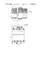
- FIG. 2shows a typical cross section of the pipe seam in accordance with the instant invention.
- FIG. 3shows the portion shown in FIG. 2 after the provision of the sealing ring groove.
- FIG. 4is similar to FIG. 3 showing the placement of the bedding material.
- FIG. 5is similar to FIG. 4 showing the positioning of the sealing ring.
- FIG. 1shows pipe section 1.
- the spigot end 2 and bell portion 5 of the pipe section 1are shown broken away to illustrate the normal relationship of these end portions just before the spigot end is seated within the bell portion to form bell and spigot joint 12.
- Pipe section 1is distinctive in that the entire outer surface including the spigot end and bell portion are covered with helical ribs 7.
- Pipe section 1can be formed by a number of known processes.
- a ribbon of thermoplastic materialhaving defined on at least one side thereof of plurality of ribs 7, is wound on a mandrel.
- the outer diameter of the mandrelthus defines the inner diameter of the pipe section.
- the adjacent edges of the ribbonare overlapped and cemented or welded and thus seam 8 is formed between adjacent helical convolutions of this ribbon.
- Spigot end 2includes annular groove 4 in which is placed sealing gasket 3. Sealing gasket 3 and its relation to the depth of annular groove 4 is such that sealing gasket 3 extends radially outwardly an adequate distance to engage an inner circumferential portion of the inner surface 6 of bell portion 5 in order to form a fluid-tight bell and spigot joint.
- a bedding material 14which shall be set forth in greater detail with reference to subsequent figures.
- FIG. 2shows a detail of a typical longitudinal section of pipe section 1. The center portion of this longitudinal section has been eliminated and the opposite sides of the pipe are moved into juxtaposition for clarity. Between or adjacent a pair of parallel ribs 7 is positioned helical seam 8.
- seam 8can be described as having an inner seam struction 9 and an outer seam structure 10.
- the inner seam structure 9comprises an intimately contacting pair of surfaces of the web portion of adjacent helical convolutions of the thermoplastic ribbon.
- the outer seam structure 10utilizes a capturing rib 11 which is of similar dimensions to ribs 7 but has axially facing notch extending along its length. Within this notch of capturing rib 11 is edge 13.
- FIG. 3shows the same typical section as shown in FIG. 2 after severing and machining of annular groove 4 into its outer surface.
- This machining operationcan be done with conventional rotary bits or routers.
- annular ring 4has a generally semicircular shape in cross section, annular groove 4 passes through any intersecting rib 7 as can be seen in the lower portion of FIG. 3. At some point, annular groove 4 intersects the helical seam 8. In so doing, a substantial portion of the joint structure is removed. This can be seen in the upper portion of FIG. 3. At this intersection of the helical seam and the annular groove, the outer seam structure 10 has been machined away, leaving only the inner seam structure 9. This intersection, and the destruction of the outer seam structure 10 is inevitable if ring groove 4 is to be defined to a depth into the outer surface of spigot end 2 to form a reasonably continuous seat for subsequently applied sealing gasket.
- FIG. 4shows the spigot end of FIG. 3 with bedding material 14 applied.
- Bedding material 14is placed at the radially innermost surface of annular groove 4.
- sealing ring 3is radially stretched around and rolled to a position on spigot 2 on the side opposite annular groove 4 from the end surface of the spigot end.
- Embedded in bedding material 14is reinforcing material 15.
- Reinforcing material 15consists of an elongated, flexible, porous reinforcing material of relatively high tensile strength.
- this materialis a ribbon of woven fiberglass which, compared to the thermoplastic material making up spigot end 2 and the elastomeric sealing gasket 3, is relatively inextensible. Note that in FIG. 4, two layers of reinforcing material 15 are shown overlying the intersection of the helical seam 8 with the annular groove 4. This should be contrasted with the single layer of reinforcing material 15 on the opposite side of the annular groove 4.
- FIG. 5shows an enlarged sectional view of the completed spigot end 2 of FIG. 1. Sealing gasket 3 has been rolled forward and has come to rest in annular groove 4. In so doing, gasket 3 has displaced the fluid, settable material comprising the bedding material 14. The lower portion of FIG. 5 shows bedding material 14 having been extruded out of the groove slightly and overlapping the adjacent cut surfaces of ribs 7.
- Bedding material 14is preferably elastomeric, fluid settable material such as a reactive polyurethane system.
- a reactive polyurethane systemSuch polyurethanes have excellent adhesion characteristics, even to such diverse materials as embodied in the preferred embodiment.
- pipe section 1is made of unplasticized PVC compound of conventional form.
- Sealing gasket 3preferably is a solid, annular gasket of circular cross section of EPDM (ethylene propylene diene monomere) rubber having a hardness of 55 durometer.
- EPDMethylene propylene diene monomere
- Other sealing gasketsmay be used, for example, sealing gasket 3 could have an annular cavity positioned approximate the center of the circular body or it could be a closed cell foam of an elastomeric material.
- bedding material 14While a urethane bedding material is preferred, other materials may be useful. For example, a hot melt adhesive may be used.
- bedding material 14must be in a fluid state long enough to permit the embedding of reinforcement material 15, and the placement of the sealing gasket 3 during this fluid state in order to permit intimate setting of the sealing gasket 3.
- bedding material 14 in its cured statehas a hardness which is less than that of the PVC material making up the body of pipe section 1.
- bedding material 14should have a hardness which is greater than or equal to that of the sealing gasket 3. At the very least, however, bedding material 14 should not be characterized as "brittle".
- Reinforcing materialis preferably a ribbon of woven fiberglass. Other materials may be substituted. Such substituted material should have the characteristics of being elongated, flexible, porous enough to be impregnated by the chosen bedding material, substantially longitudinally inextensile (high modulous in tension), and should conform reasonably well to the confined space between the sealing gasket 3 and the innermost annular surface of the annular groove 4.
- the method of forming the gasketed spigotwill now be set forth in greater detail.
- the spigot end of pipe sectionwas provided as shown in FIG. 3. As stated above, this is preferably done by machining the annular groove to the depth shown, which groove passes through the intersecting ribs and at least the outer portion of the helical seam 8. It is desirable to set the depth so as to intersect the continuous web portion of the thermoplastic ribbon making up the pipe in order to present a smooth surface on which bedding material 14 can be placed. However, since bedding material also serves to close any gaps between a subsequently installed sealing ring 3 and the groove 4, a shallower cut could be made and the gaps filled with the bedding material 14. Also, the machining step is not necessary although it is desirable since it does leave a fresh, easily bonded-to surface with beneficial effect to the overall strength of the finished spigot end. An alternative system would be to melt groove 4 through intersecting ribs 7.
- the thus machined or grooved pipe sectionis placed on a rack of conventional form which permits the pipe section to be rotated.
- the intersection of the helical seam 8 and the annular groove 4is determined.
- the chosen bedding compoundis applied to the annular groove 4 and, either subsequently or simultaneously with this application, the fiberglass ribbon is placed in the groove by initially adhering one end of the ribbon over this intersection.
- the fiberglass ribbonpreferably impregnated with a portion of the bedding material, is payed out and placed in the annular groove 4.
- the placement of the fiberglass ribbonis begun just one side of this intersection of the annular groove with the helical joint so that on completing one revolution, the fiberglass ribbon wrapping operation is terminated just on the other side of the intersection of the groove and the helical joint. In this manner, the intersection of the groove and helical joint is doubly reinforced.
- sealing gasket 3While not necessary to the disclosed method, it has been found desirable to stretch sealing gasket 3 over the machined end of the spigot prior to the application of the bedding material and reinforcing material.
- the sealing gasket 3is rolled past groove 4 to assure that the amount of stretch is equalized around the circumference of the ring. This also places the sealing gasket 3 in a convenient position so that, once the bedding material/reinforcing material is in place in the annular groove 4, the sealing gasket can merely be “rolled” into the groove.
- sealing gasket 3radially contracts by its own elasticity. This acts to smooth the bedding material 14, forcing the bedding material to intimately contact the inner portion of the sealing gasket 3 and virtually all portions of the annular groove 4. This is desirable since this also acts to force fill any chance gap between adjacent or contacting portions of the helical joint with the bedding material. This is especially desirable since much of the joint has been eliminated by the provision of the annular groove 4.
- the benefits of Applicant's inventionbecomes apparent.
- the spigothas adequate strength to overcome any normal structural stresses experienced while positioned within the bell portion 5.
- the spigot endcan be expected to be subjected to substantially greater stresses.
- the pipe section in accordance with Applicant's inventioncan endure such high impacts with no cracking associated with the annular groove.
- the bedding materialacts to transmit such stresses around and throughout the sealing gasket/annular groove structure, thus eliminating the tendency of a stress concentration to take place in a portion of the grooved area.
- the incorporation of the fiberglass webbing or ribbonacts to prevent the impact stress from collapsing the pipe in the annular groove area. Such a collapse would tend to pull apart the somewhat weakened portion located at the intersection of the helical joint and the annular groove.
Landscapes
- Engineering & Computer Science (AREA)
- General Engineering & Computer Science (AREA)
- Mechanical Engineering (AREA)
- Joints With Sleeves (AREA)
Abstract
Description
Claims (10)
Priority Applications (1)
| Application Number | Priority Date | Filing Date | Title |
|---|---|---|---|
| US06/280,665US4398726A (en) | 1981-07-06 | 1981-07-06 | Pipe section including a gasketed spigot end and method of making the same |
Applications Claiming Priority (1)
| Application Number | Priority Date | Filing Date | Title |
|---|---|---|---|
| US06/280,665US4398726A (en) | 1981-07-06 | 1981-07-06 | Pipe section including a gasketed spigot end and method of making the same |
Publications (1)
| Publication Number | Publication Date |
|---|---|
| US4398726Atrue US4398726A (en) | 1983-08-16 |
Family
ID=23074067
Family Applications (1)
| Application Number | Title | Priority Date | Filing Date |
|---|---|---|---|
| US06/280,665Expired - Fee RelatedUS4398726A (en) | 1981-07-06 | 1981-07-06 | Pipe section including a gasketed spigot end and method of making the same |
Country Status (1)
| Country | Link |
|---|---|
| US (1) | US4398726A (en) |
Cited By (17)
| Publication number | Priority date | Publication date | Assignee | Title |
|---|---|---|---|---|
| US4456266A (en)* | 1981-12-14 | 1984-06-26 | General Electric Company | Throttle bushing |
| USD342567S (en) | 1989-10-11 | 1993-12-21 | Sonn Chsen A.S. | Gasket for corrugated pipes |
| US5644832A (en)* | 1992-09-18 | 1997-07-08 | Kanao; Shiro | Method of providing sealing connection between corrugated spiral pipes |
| US20030107695A1 (en)* | 1998-07-24 | 2003-06-12 | Masumi Kubo | Liquid crystal display device |
| US20030132578A1 (en)* | 2002-01-11 | 2003-07-17 | Nilsson Lars E.W. | Method and apparatus for providing a sealing gasket on a tubular element |
| US6695320B2 (en)* | 2000-05-12 | 2004-02-24 | Jeff Busby | Gasket and gasket tape and method of making and using the same |
| US20040041356A1 (en)* | 2000-05-12 | 2004-03-04 | Aviation Devices And Electronic Components, Llc. | Gasket material having a PTFE core and a method of making a using the same |
| US20040070156A1 (en)* | 2000-05-12 | 2004-04-15 | Aviation Devices And Electronic Components, L.L.C. | Gasket material having a durable, non-tacky skin and a tacky side, and a method of making and using the same |
| US20050109190A1 (en)* | 2003-11-26 | 2005-05-26 | Aviation Devices & Electronic Components, Inc. | Dampening material for a drum |
| US7229516B2 (en) | 2000-05-12 | 2007-06-12 | Aviation Devices & Electronic Components, Llc | Foam bodied gasket and gasket tape and method of making and using the same |
| US20070245789A1 (en)* | 2006-04-21 | 2007-10-25 | Zepp William L | Method of producing helically corrugated metal pipe and related pipe construction |
| US20090174184A1 (en)* | 2008-01-09 | 2009-07-09 | Lin Bi-Ting | Working method of the external threaded frp (fiberglass-reinforced plastic) pipe and fitting |
| US20150285416A1 (en)* | 2012-10-18 | 2015-10-08 | Airbus Operations Limited | Method of manufacturing or repairing a pipe |
| JP2016070390A (en)* | 2014-09-30 | 2016-05-09 | 積水化学工業株式会社 | Connection structure of underground pipe |
| US10260664B2 (en)* | 2013-03-14 | 2019-04-16 | Actuant Corporation | Pipe end seal assembly |
| US11300369B2 (en)* | 2018-11-22 | 2022-04-12 | Hyundai Motor Company | Water cooling apparatus and water cooling type power module assembly including the same |
| US20240110649A1 (en)* | 2022-09-30 | 2024-04-04 | B. Braun Avitum Ag | Radial seal with minimal dead space |
Citations (8)
| Publication number | Priority date | Publication date | Assignee | Title |
|---|---|---|---|---|
| US843892A (en)* | 1905-10-21 | 1907-02-12 | Edward Theodore Ingham And Joshua Lister Ingham | Pipe-joint. |
| US1057267A (en)* | 1909-09-01 | 1913-03-25 | Reinforced Concrete Pipe Company | Sewer-pipe joint. |
| US2138946A (en)* | 1936-06-10 | 1938-12-06 | Lock Joint Pipe Co | Method for sealing pipe joints |
| FR1476758A (en)* | 1966-02-28 | 1967-04-14 | Method and device for connecting tubes or pipes | |
| CA970797A (en)* | 1972-04-06 | 1975-07-08 | Lewis R. Keyser | Pipe assembly |
| US3904213A (en)* | 1973-05-14 | 1975-09-09 | Interpace Corp | Corrosion protective band for underground pipe joints with metal parts |
| US3937641A (en)* | 1974-08-30 | 1976-02-10 | General Electric Company | Method of assembling adhesive joint |
| SU781481A1 (en)* | 1978-07-18 | 1980-11-23 | Всесоюзный Научно-Исследовательский Институт По Монтажным И Специальным Строительным Работам | Pipeline ends connection method |
- 1981
- 1981-07-06USUS06/280,665patent/US4398726A/ennot_activeExpired - Fee Related
Patent Citations (8)
| Publication number | Priority date | Publication date | Assignee | Title |
|---|---|---|---|---|
| US843892A (en)* | 1905-10-21 | 1907-02-12 | Edward Theodore Ingham And Joshua Lister Ingham | Pipe-joint. |
| US1057267A (en)* | 1909-09-01 | 1913-03-25 | Reinforced Concrete Pipe Company | Sewer-pipe joint. |
| US2138946A (en)* | 1936-06-10 | 1938-12-06 | Lock Joint Pipe Co | Method for sealing pipe joints |
| FR1476758A (en)* | 1966-02-28 | 1967-04-14 | Method and device for connecting tubes or pipes | |
| CA970797A (en)* | 1972-04-06 | 1975-07-08 | Lewis R. Keyser | Pipe assembly |
| US3904213A (en)* | 1973-05-14 | 1975-09-09 | Interpace Corp | Corrosion protective band for underground pipe joints with metal parts |
| US3937641A (en)* | 1974-08-30 | 1976-02-10 | General Electric Company | Method of assembling adhesive joint |
| SU781481A1 (en)* | 1978-07-18 | 1980-11-23 | Всесоюзный Научно-Исследовательский Институт По Монтажным И Специальным Строительным Работам | Pipeline ends connection method |
Cited By (19)
| Publication number | Priority date | Publication date | Assignee | Title |
|---|---|---|---|---|
| US4456266A (en)* | 1981-12-14 | 1984-06-26 | General Electric Company | Throttle bushing |
| USD342567S (en) | 1989-10-11 | 1993-12-21 | Sonn Chsen A.S. | Gasket for corrugated pipes |
| US5644832A (en)* | 1992-09-18 | 1997-07-08 | Kanao; Shiro | Method of providing sealing connection between corrugated spiral pipes |
| US20030107695A1 (en)* | 1998-07-24 | 2003-06-12 | Masumi Kubo | Liquid crystal display device |
| US7229516B2 (en) | 2000-05-12 | 2007-06-12 | Aviation Devices & Electronic Components, Llc | Foam bodied gasket and gasket tape and method of making and using the same |
| US6695320B2 (en)* | 2000-05-12 | 2004-02-24 | Jeff Busby | Gasket and gasket tape and method of making and using the same |
| US20040041356A1 (en)* | 2000-05-12 | 2004-03-04 | Aviation Devices And Electronic Components, Llc. | Gasket material having a PTFE core and a method of making a using the same |
| US20040070156A1 (en)* | 2000-05-12 | 2004-04-15 | Aviation Devices And Electronic Components, L.L.C. | Gasket material having a durable, non-tacky skin and a tacky side, and a method of making and using the same |
| US20030132578A1 (en)* | 2002-01-11 | 2003-07-17 | Nilsson Lars E.W. | Method and apparatus for providing a sealing gasket on a tubular element |
| US20050109190A1 (en)* | 2003-11-26 | 2005-05-26 | Aviation Devices & Electronic Components, Inc. | Dampening material for a drum |
| US20050200059A1 (en)* | 2003-11-26 | 2005-09-15 | Aviation Devices & Electronic Components, Inc. | Dampening material for a drum |
| US20070245789A1 (en)* | 2006-04-21 | 2007-10-25 | Zepp William L | Method of producing helically corrugated metal pipe and related pipe construction |
| US20090174184A1 (en)* | 2008-01-09 | 2009-07-09 | Lin Bi-Ting | Working method of the external threaded frp (fiberglass-reinforced plastic) pipe and fitting |
| US20150285416A1 (en)* | 2012-10-18 | 2015-10-08 | Airbus Operations Limited | Method of manufacturing or repairing a pipe |
| US10260664B2 (en)* | 2013-03-14 | 2019-04-16 | Actuant Corporation | Pipe end seal assembly |
| JP2016070390A (en)* | 2014-09-30 | 2016-05-09 | 積水化学工業株式会社 | Connection structure of underground pipe |
| US11300369B2 (en)* | 2018-11-22 | 2022-04-12 | Hyundai Motor Company | Water cooling apparatus and water cooling type power module assembly including the same |
| US20240110649A1 (en)* | 2022-09-30 | 2024-04-04 | B. Braun Avitum Ag | Radial seal with minimal dead space |
| US12404955B2 (en)* | 2022-09-30 | 2025-09-02 | B. Braun Avitum Ag | Radial seal with minimal dead space |
Similar Documents
| Publication | Publication Date | Title |
|---|---|---|
| US4398726A (en) | Pipe section including a gasketed spigot end and method of making the same | |
| JPH024300Y2 (en) | ||
| US8646489B2 (en) | Connection structure of wave-shaped synthetic resin pipes, wave-shaped synthetic resin pipes used for the connection structure, and manufacturing method thereof | |
| US6679966B1 (en) | Liner with a tubular film that is coated with a nonwoven | |
| EP1113208B1 (en) | Impermeable hose and a process for manufacturing the same | |
| US5806567A (en) | Heat insulated hose | |
| US3837947A (en) | Method of forming an inflatable member | |
| GB1572628A (en) | Pipe coupling and method of making same | |
| GB1579125A (en) | Heat-insulated pipe-lines | |
| EP2937611B1 (en) | Marine hose and manufacturing method therefor | |
| US4081303A (en) | Pipe liner laminate and method of making a pipe with said liner | |
| US3612580A (en) | Hose splice | |
| US3717180A (en) | Flexible hose | |
| US4366842A (en) | Flanged hose and method of making | |
| US3799825A (en) | Hoses and pipes | |
| US3580616A (en) | Reinforced expansion | |
| US4257837A (en) | Seal splice | |
| US2308343A (en) | Self-sealing petrol pipe | |
| US3847693A (en) | Buoyant hose and method for making same | |
| JP2006064173A (en) | Corrugated composite tube | |
| JPH08193682A (en) | Floating-arch type expansion joint using fep liner reinforced by plurality of cloth ply covered with elastomer outer layer stuck on glass fiber cloth layer | |
| WO2010052858A1 (en) | Pipe joint and method of manufacturing same | |
| JP3839923B2 (en) | Rubber hose flange structure and flexible joint | |
| WO1995033953A2 (en) | Improvements relating to pipeline insulation and anticorrosion protection | |
| US4322462A (en) | Seal splice |
Legal Events
| Date | Code | Title | Description |
|---|---|---|---|
| AS | Assignment | Owner name:JOHNS-MANVILLE CORPORATION, KEN-CARYL RANCH, CO A Free format text:ASSIGNMENT OF ASSIGNORS INTEREST.;ASSIGNOR:HEISLER, ROBERT W.;REEL/FRAME:003899/0690 Effective date:19810130 | |
| AS | Assignment | Owner name:MANVILLE SERVICE CORPORATION, KEN-CARYL RANCH, COU Free format text:ASSIGNMENT OF ASSIGNORS INTEREST.;ASSIGNOR:JOHNS-MANVILLE CORPORATION;REEL/FRAME:003935/0163 Effective date:19811030 | |
| MAFP | Maintenance fee payment | Free format text:PAYMENT OF MAINTENANCE FEE, 4TH YEAR, PL 96-517 (ORIGINAL EVENT CODE: M170); ENTITY STATUS OF PATENT OWNER: LARGE ENTITY Year of fee payment:4 | |
| FEPP | Fee payment procedure | Free format text:MAINTENANCE FEE REMINDER MAILED (ORIGINAL EVENT CODE: REM.); ENTITY STATUS OF PATENT OWNER: LARGE ENTITY | |
| FEPP | Fee payment procedure | Free format text:SURCHARGE FOR LATE PAYMENT, PL 96-517 (ORIGINAL EVENT CODE: M176); ENTITY STATUS OF PATENT OWNER: LARGE ENTITY | |
| MAFP | Maintenance fee payment | Free format text:PAYMENT OF MAINTENANCE FEE, 8TH YEAR, PL 96-517 (ORIGINAL EVENT CODE: M171); ENTITY STATUS OF PATENT OWNER: LARGE ENTITY Year of fee payment:8 | |
| REFU | Refund | Free format text:REFUND OF EXCESS PAYMENTS PROCESSED (ORIGINAL EVENT CODE: R169); ENTITY STATUS OF PATENT OWNER: LARGE ENTITY | |
| REFU | Refund | Free format text:REFUND OF EXCESS PAYMENTS PROCESSED (ORIGINAL EVENT CODE: R169); ENTITY STATUS OF PATENT OWNER: LARGE ENTITY | |
| FEPP | Fee payment procedure | Free format text:MAINTENANCE FEE REMINDER MAILED (ORIGINAL EVENT CODE: REM.); ENTITY STATUS OF PATENT OWNER: LARGE ENTITY | |
| LAPS | Lapse for failure to pay maintenance fees | ||
| FP | Lapsed due to failure to pay maintenance fee | Effective date:19950816 | |
| AS | Assignment | Owner name:CHIAO TUNG BANK, SILICON VALLEY BRANCH, AS AGENT, Free format text:SECURITY AGREEMENT;ASSIGNOR:J-M MANUFACTURING COMPANY, INC., A DELAWARE CORPORATION;REEL/FRAME:016712/0431 Effective date:20051101 | |
| AS | Assignment | Owner name:MEGA INTERNATIONAL COMMERCIAL BANK CO., LTD., SILI Free format text:AMENDED AND RESTATED SECURITY AGREEMENT;ASSIGNOR:J-M MANUFACTURING COMPANY, INC.;REEL/FRAME:020288/0762 Effective date:20071221 | |
| STCH | Information on status: patent discontinuation | Free format text:PATENT EXPIRED DUE TO NONPAYMENT OF MAINTENANCE FEES UNDER 37 CFR 1.362 |